EP1887326B1 - Öffnungsglied und differenzdruck-strömungsmesser und strömungsregulierungseinrichtung mit dem öffnungsglied - Google Patents
Öffnungsglied und differenzdruck-strömungsmesser und strömungsregulierungseinrichtung mit dem öffnungsglied Download PDFInfo
- Publication number
- EP1887326B1 EP1887326B1 EP06756686.9A EP06756686A EP1887326B1 EP 1887326 B1 EP1887326 B1 EP 1887326B1 EP 06756686 A EP06756686 A EP 06756686A EP 1887326 B1 EP1887326 B1 EP 1887326B1
- Authority
- EP
- European Patent Office
- Prior art keywords
- pressure
- tube portion
- orifice member
- orifice
- nut
- Prior art date
- Legal status (The legal status is an assumption and is not a legal conclusion. Google has not performed a legal analysis and makes no representation as to the accuracy of the status listed.)
- Active
Links
Images


Classifications
-
- G—PHYSICS
- G01—MEASURING; TESTING
- G01F—MEASURING VOLUME, VOLUME FLOW, MASS FLOW OR LIQUID LEVEL; METERING BY VOLUME
- G01F1/00—Measuring the volume flow or mass flow of fluid or fluent solid material wherein the fluid passes through a meter in a continuous flow
- G01F1/05—Measuring the volume flow or mass flow of fluid or fluent solid material wherein the fluid passes through a meter in a continuous flow by using mechanical effects
- G01F1/34—Measuring the volume flow or mass flow of fluid or fluent solid material wherein the fluid passes through a meter in a continuous flow by using mechanical effects by measuring pressure or differential pressure
- G01F1/36—Measuring the volume flow or mass flow of fluid or fluent solid material wherein the fluid passes through a meter in a continuous flow by using mechanical effects by measuring pressure or differential pressure the pressure or differential pressure being created by the use of flow constriction
- G01F1/40—Details of construction of the flow constriction devices
- G01F1/42—Orifices or nozzles
-
- F—MECHANICAL ENGINEERING; LIGHTING; HEATING; WEAPONS; BLASTING
- F15—FLUID-PRESSURE ACTUATORS; HYDRAULICS OR PNEUMATICS IN GENERAL
- F15D—FLUID DYNAMICS, i.e. METHODS OR MEANS FOR INFLUENCING THE FLOW OF GASES OR LIQUIDS
- F15D1/00—Influencing flow of fluids
-
- G—PHYSICS
- G01—MEASURING; TESTING
- G01F—MEASURING VOLUME, VOLUME FLOW, MASS FLOW OR LIQUID LEVEL; METERING BY VOLUME
- G01F1/00—Measuring the volume flow or mass flow of fluid or fluent solid material wherein the fluid passes through a meter in a continuous flow
- G01F1/05—Measuring the volume flow or mass flow of fluid or fluent solid material wherein the fluid passes through a meter in a continuous flow by using mechanical effects
- G01F1/34—Measuring the volume flow or mass flow of fluid or fluent solid material wherein the fluid passes through a meter in a continuous flow by using mechanical effects by measuring pressure or differential pressure
- G01F1/36—Measuring the volume flow or mass flow of fluid or fluent solid material wherein the fluid passes through a meter in a continuous flow by using mechanical effects by measuring pressure or differential pressure the pressure or differential pressure being created by the use of flow constriction
- G01F1/40—Details of construction of the flow constriction devices
- G01F1/44—Venturi tubes
-
- G—PHYSICS
- G01—MEASURING; TESTING
- G01F—MEASURING VOLUME, VOLUME FLOW, MASS FLOW OR LIQUID LEVEL; METERING BY VOLUME
- G01F15/00—Details of, or accessories for, apparatus of groups G01F1/00 - G01F13/00 insofar as such details or appliances are not adapted to particular types of such apparatus
- G01F15/18—Supports or connecting means for meters
- G01F15/185—Connecting means, e.g. bypass conduits
-
- Y—GENERAL TAGGING OF NEW TECHNOLOGICAL DEVELOPMENTS; GENERAL TAGGING OF CROSS-SECTIONAL TECHNOLOGIES SPANNING OVER SEVERAL SECTIONS OF THE IPC; TECHNICAL SUBJECTS COVERED BY FORMER USPC CROSS-REFERENCE ART COLLECTIONS [XRACs] AND DIGESTS
- Y10—TECHNICAL SUBJECTS COVERED BY FORMER USPC
- Y10T—TECHNICAL SUBJECTS COVERED BY FORMER US CLASSIFICATION
- Y10T137/00—Fluid handling
- Y10T137/206—Flow affected by fluid contact, energy field or coanda effect [e.g., pure fluid device or system]
- Y10T137/212—System comprising plural fluidic devices or stages
Definitions
- the present invention relates to an external orifice member used for a fluid transportation channel in, for example, fluid transportation piping used in various industrial fields, including chemical plants, semiconductor production, food production, and biotechnology, and relates to a differential-pressure flow meter and flow-regulating apparatus using the same.
- An orifice member is used as a component of, for example, a differential-pressure flow meter or a flow-regulating device installed in a fluid transportation channel.
- a known example of such an orifice member is an orifice device described below in Patent Document 1.
- This orifice device is formed by inserting an orifice inside a tube that has joints at both ends.
- the space between the tube and the orifice is sealed with, for example, an O-ring.
- Patent Citation 1 Japanese Unexamined Patent Application, Publication No. 2003-194283
- the tube and the orifice can be made of materials that are less likely to cause contamination and leaching of impurities.
- the O-ring used to seal the tube and the orifice is limited to materials that maintain the sealing performance.
- DE4015107 describes a nozzle for flow measurement on heating bodies in heating systems carrying heating liquid media such as water.
- the nozzle is installed between the heating body and its fitting to the system.
- Radial bores are arranged before and after an aperture mounted in the measurement nozzle's flow channel between the connections for the heating body and its system fitting.
- the bores open into closable connection channels of an adapter. Each channel has a differential pressure measurement arrangement output.
- WO2004/027305A1 describes another prior art end connection for a tube fitting having a tubular member.
- the present invention has been conceived in light of the problems described above. Accordingly, it is an object of the present invention to provide an orifice member, as well as a differential-pressure flow meter and a flow-regulating device using the orifice member, wherein a purging operation carried out when changing the circulated fluid is simplified, contamination and leaching of impurities into the circulated fluid is less likely to occur, and manufacturing is easy.
- the present invention provides the following solutions.
- a first aspect of the present invention provides an orifice member according to claim 1.
- the orifice member having such a structure is used as an orifice by connecting both ends of the tube portion to objects such as pipelines or various devices.
- the connection structure between the tube portion and the objects are threaded nuts.
- the tube portion and the orifice are integrated (in other words, the tube portion and the orifice are provided as single member), and there is no joint, which may cause accumulation of fluid, between the tube portion and the orifice.
- the orifice member when the fluid circulated through the channel is changed, the remaining fluid in the channel is reliably pushed out by the fluid newly supplied to the channel, and the fluid in the channel can be quickly changed.
- the tube portion and the orifice are integrated, only a small number of components is required, production is easy, and a member, such as an O-ring, that may cause contamination of the channel does not have to be provided.
- Such an orifice member can be manufactured by injection molding using a mold or by machining (cutting etc.).
- a sleeve inserted into the end of the tube portion and forming a large-diameter portion by widening the section near the end of the tube portion outwards in the radial direction may be provided.
- connection end the end of the orifice which is passed through the nut (hereinafter, referred to as the "connection end") is connected to the object to be connected to, which has a male threaded portion formed on the outer circumferential surface of the connection end for connecting to the tube portion.
- connection end of the tube portion is inserted into the nut whose inner circumferential surface includes the engagement protrusion. Then, the sleeve is inserted into the connection end to form, near the end, the large-diameter portion that engages with the engagement protrusion.
- connection end of the tube portion moves relatively close to the connection end of the object.
- the connection end of the tube portion and the connection end of the object are fixed in an airtight, liquid-tight manner.
- connection end of the tube portion and the connection end of the object are freed.
- connection and disconnection with the object can be easily carried out by moving the nut.
- the sleeve may be an engagement portion that is shaped to engage with the connection end of the object.
- the connection end of the tube portion and the connection end of the object can be satisfactorily connected.
- the orifice member according to the present invention instead of having a structure as described above in which the sleeve is inserted into the connection end of the tube portion, has a structure in which, the end of the tube portion passing through the nut comprises a large-diameter portion having flexibility, having a diameter larger than other sections, and internally receiving a connection end of the object.
- the orifice member having such a structure is connected to the object whose tube-portion-connecting end forms an insertion portion that is inserted into the connection end of the tube portion and whose outer circumferential surface near the tube-portion-connecting end is provided with a male threaded portion.
- At least one of the ends of the tube portion is flexible and is inserted into the nut having the engagement protrusion on inner circumferential surface.
- the section near the end inserted into the nut of the tube portion has diameter larger than other sections. This large-diameter portion engages with the engagement protrusion formed on the inner circumferential surface of the nut by internally receiving the insertion portion of the object and by its deformation being restricted.
- connection end of the tube portion moves, together with the nut, relatively close to the connection end of the object.
- connection end of the tube portion and the connection end of the object are freed.
- connection and disconnection of the object can be easily carried out by moving the nut.
- Another aspect of the present invention provides a differential-pressure flow meter including the orifice member according to the present invention, a first pressure-measuring device may be connected to one end of the tube portion of the orifice member, and a second pressure-measuring device may be connected to the other end of the tube portion of the orifice member.
- an orifice member that does not have a joint, which may cause accumulation of fluid is used between the tube portion and the orifice. Therefore, when the fluid circulated through the channel is changed, the remaining fluid in the channel is reliably pushed out by the fluid newly supplied to the channel, and the fluid in the channel can be quickly changed.
- the tube portion and the orifice are integrated, only a small number of components is required, production is easy, and a member, such as an O-ring, that may cause contamination of the channel does not have to be provided.
- Another aspect of the present invention provides a flow-regulating device including a differential-pressure flow meter using the orifice member according to the present invention, and a flow-regulating valve connected to the upstream or downstream side of the differential-pressure flow meter.
- an orifice member of the differential-pressure flow meter does not have a joint, which may cause accumulation of fluid, between the tube portion and the orifice. Therefore, when the fluid circulated through the channel is changed, the remaining fluid in the channel is reliably pushed out by the fluid newly supplied to the channel, and the fluid in the channel can be quickly changed.
- the tube portion and the orifice are integrated, only a small number of components is required, production is easy, and a member, such as an O-ring, that may cause contamination of the channel does not have to be provided.
- purging can be carried out easily and reliably when changing the fluid to be circulated, production is easy because the number of components is small, and contamination of the circulated fluid is less likely to occur because members, such as O-rings, that may cause contamination do not have to be disposed inside the channel.
- a flow-regulating device 10 is provided in a fluid transportation pipe W used in various industrial fields, including chemical plants, semiconductor production, food production, and biotechnology, and is used to regulate the flow of fluid supplied by back-pressure from the upstream side to the downstream side through the fluid transportation pipe W.
- the flow-regulating device 10 is used for a fluid transportation pipe that transports fluid at a back-pressure of about 50k to 500k [Pa] by applying pressure, by pumping with a fluid-transporting pump, or by means for applying potential energy.
- the flow-regulating device 10 includes an orifice member 11, a first pressure-measuring device 12 that is connected to the upstream side of the orifice member 11 to measure the fluid pressure at this position, a second pressure-measuring device 13 that is connected to the downstream side of the orifice member 11 to measure the fluid pressure at this position, and a flow-regulating valve 14 that is connected to the upstream side of the first pressure-measuring device 12 or the downstream side of the second pressure-measuring device 13 to control the flow volume of the fluid supplied from upstream to downstream.
- the proportionality coefficient k in Equation (1) is a constant depending on the shape or hole-diameter of the orifice and is determined by actual measurements.
- the flow-regulating valve 14 is connected to the downstream side of the second pressure-measuring device 13. In this way, sufficiently great back-pressure can be applied to the first and second pressure-measuring devices 12 and 13 to stabilize the properties of the first and second pressure-measuring devices 12 and 13, and the measurement accuracy of the first and second pressure measuring devices 12 and 13 is less likely to be affected even when there is a pressure change in the fluid supplied to the flow-regulating device 10.
- a pressure-regulating valve 16 for suppressing pressure change of the fluid supplied to the first pressure-measuring device 12 so as to maintain a predetermined pressure is provided on the upstream side of the first pressure-measuring device 12.
- the measurement accuracy of the first and second pressure-measuring devices 12 and 13 is less likely to be affected even when there is a pressure change in the fluid supplied to the flow-regulating device 10 due to disturbance caused by, for example, other pipe systems connected in parallel with the fluid transportation pipe W whose flow rate is to be regulated.
- the pressure-regulating valve 16 may be configured such that pressure regulation is carried out by manual operation conducted by an operator.
- a display device that allows visual confirmation of a measurement value (i.e., pressure of the fluid sent out from the pressure-regulating valve 16).
- the display device may be an analog meter that displays a measurement value by the position of a needle or a digital meter that displays the measurement value as a numeric value.
- the pressure-regulating valve 16 may be an automatic valve, such as an air-operated valve using pneumatic pressure (electropneumatic regulator) .
- pneumatic pressure electropneumatic regulator
- the flow-regulating valve 14 is configured with, for example, a throttle mechanism having a needle-valve structure and a throttle-adjusting device for adjusting the needle position of the throttle mechanism.
- the throttle-adjusting device includes, for example, a motor and a conversion mechanism (for example, a screw-nut system) for converting the rotation of the rotary shaft of the motor into displacement of a needle.
- a stepping motor whose rotary shaft rotation can be controlled in a highly accurate manner is used as the motor for the throttle-adjusting device.
- the needle position can be controlled in a highly accurate manner (i.e., the amount of throttle of the throttle mechanism can be controlled in a highly accurate manner).
- this stepping motor is controlled by the control device 17. More specifically, the stepping motor rotates its rotary shaft by an angle proportional to the number of pulses in a drive signal sent from the control device 17.
- the control device 17 controls the degree of opening of the flow-regulating valve 14 such that the difference between the measurement values or output voltages of the first pressure-measuring device 12 and the second pressure-measuring device 13 become a predetermined value set in advance. More specifically, when the difference of the output values or the difference of the output voltages of the pressure-measuring devices are lower than a target value set in advance, the degree of opening of the flow-regulating valve 14 is increased to increase the flow rate, whereas, when the difference of the output values or the difference of the output voltages of the pressure-measuring devices are higher than the target value, the degree of opening of the flow-regulating valve 14 is decreased to decrease the flow rate.
- control device 17 controls the flow-regulating valve 14 by using a PID control method, which has excellent control accuracy and response.
- control device 17 may determine the flow rate of the fluid passing through the flow-regulating device 10 on the basis of the difference of the measurement values or output voltages of the first pressure-measuring device 12 and the second pressure-measuring device 13 and may control the degree of opening of the flow-regulating valve 14 such that the difference is eliminated.
- a tube portion 21, one end of which is connected to the first pressure-measuring device 12 and other end of which is connected to the second pressure-measuring device 13 and whose internal part forms a channel connecting the first and second pressure-measuring devices 12 and 13, and an orifice 22 provided inside the tube portion 21 are integrated.
- the orifice member 11 is formed of a material that is less likely to cause contamination of the fluid circulated through the inner channel and less likely to be affected by the fluid, for example, PFA (a copolymer of tetrafluoroethylene and perfluoroalkoxy vinyl ether).
- PFA a copolymer of tetrafluoroethylene and perfluoroalkoxy vinyl ether
- the orifice member 11 has a substantially cylindrical shape in which only a center portion 21a along the longitudinal direction of the tube portion 21 is solid.
- the center portion 21a in the longitudinal direction has a narrow hole 21b that connects one end to another end in the longitudinal direction and that is formed concentrically with the axis of the tube portion 21.
- This center portion 21a in the longitudinal direction forms the orifice 22.
- the tube portion 21 and the orifice 22 are integrated, and there is no joint between the tube portion 21 and orifice 22, which may cause accumulation of fluid.
- the orifice member 11 when the fluid circulated through the channel is changed, the remaining fluid in the channel is reliably pushed out by the fluid newly supplied to the channel, and the fluid in the channel can be quickly changed.
- the tube portion 21 and the orifice 22 are integrated, only a small number of components is required, production is easy, and a member, such as an O-ring, that may cause contamination of the channel does not have to be provided.
- Such an orifice member 11 can be manufactured by injection molding using a mold or by machining (cutting etc.).
- the inner surface of the tube portion 21 and the inner surface of the narrow hole 21b are connected by a tapered surface 21c whose diameter decreases from an edge, in the longitudinal direction, of the tube portion 21 toward the center in the longitudinal direction.
- a tapered surface 21c whose diameter decreases from an edge, in the longitudinal direction, of the tube portion 21 toward the center in the longitudinal direction.
- a nut 26 for inserting the end of the tube portion 21 and a sleeve 27 that is inserted into the end of the tube portion 21 and that forms a large-diameter portion 21d at the end of the tube portion 21 by widening the section near the end of the tube portion 21 outwards in the radial direction are provided.
- a female threaded portion 26a is provided on the inner circumferential surface, and an engagement protrusion 26b that protrudes inward in the radial direction of the nut 26 and engages with the large-diameter portion 21d is provided closer to the center portion 21a in the longitudinal direction of the tube portion 21 than the female threaded portion 26a.
- the engagement protrusion 26b is an internal flange that is formed around the entire circumference of the nut portion 26.
- the sleeve 27 is a substantially cylindrical member whose internal section forms the channel and is inserted into the tube portion 21 with one end thereof protruding from the end of the tube portion 21.
- the end protruding from the end of the tube portion 21 is an engagement portion 28 that is shaped to engage with the connection ends of the first and second pressure-measuring devices 12 and 13.
- the engagement portion 28 includes a substantially ring-shaped contact surface 28a that surrounds the open end of the channel of the sleeve 27 and that is in surface contact with an end surface of the connection end of the first and second pressure-measuring device 12 or 13 and a cylindrical portion 28b that protrudes farther than the contact surface 28a and surrounds the contact surface 28a.
- a large-diameter portion 27a that widens the tube portion 21 outwards in the radial direction is provided.
- the first pressure-measuring device 12 includes a housing 31 that forms a channel whose inner section connects the fluid transportation pipe W and the orifice member 11 and a main body of the measuring device (not shown) for measuring the fluid pressure in the housing 31.
- the second pressure-measuring device 13 has substantially the same structure as the first pressure-measuring device 12, except that the flow-regulating valve 14 is connected instead of the fluid transportation pipe W. Therefore, only the structure of the first pressure-measuring device 12 will be described, and a detailed description of the second pressure-measuring device 13 is omitted.
- the housing 31 includes a substantially ring-shaped contact surface 31a that is provided on the connection end of the inner channel, connecting to the orifice member 11, and that surrounds the open end of the channel to be in surface contact with the contact surface 28a of the sleeve 27 of the orifice member 11; a cylindrical portion 31b that protrudes farther than the contact surface 31a and surrounds the contact surface 31a; and a ring-shaped depressed portion 31c that is interposed between the contact surface 31a and the cylindrical portion 31b and into which the cylindrical portion 28b of the orifice member 11 is inserted.
- a male threaded portion 31d that is screwed into the female threaded portion 26a of the nut 26 of the orifice member 11 is formed.
- connection structure for the housing 31 and the fluid transportation pipe W (in the case of the second pressure-measuring device 13, the connection structure with the flow-regulating valve 14).
- the contact surface 28a forming the engagement portion 28 of the sleeve 27 and the contact surface 31a of the housing 31 are pushed towards each other while being in surface contact, and the cylindrical portion 28b forming the engagement portion 28 of the sleeve 27 is inserted into the depressed portion 31c of the housing 31. In this way, the engagement portion 28 and the housing 31 are fixed in an airtight, liquid-tight manner.
- connection and disconnection operations of the orifice member 11 and the second pressure-measuring device 13 are the same as the connection and disconnection operations of the orifice member 11 and the first pressure-measuring device 12.
- connection and disconnection with the pressure-measuring devices can be easily carried out by moving the nut 26.
- the sleeve 27 is structured to include the engagement portion 28.
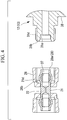
- the example is not limited thereto, and instead of the sleeve 27, a ring-shaped sleeve 37 that does not include an engagement portion 28 may be inserted farther than the end of the tube portion 21 to form a large-diameter portion 21d in the tube portion 21, as shown in Figs. 4 and 5 .
- each of the first pressure-measuring device 12 and the second pressure-measuring device 13 includes, instead of the housing 31, a housing 38 that has a structure in which the depressed portion 31c is eliminated from the housing 31.
- a first embodiment of a flow-regulating device according to the present invention will be described below with reference to Figs. 6 and 7 .
- a flow-regulating device 40 is mainly characterized in that, instead of the orifice member 11, the first pressure-measuring device 12, and the second pressure-measuring device 13 of the flow-regulating device 10 according to the first example, an orifice member 41, a first pressure-measuring device 42, and a second pressure-measuring device 43 having connection structures, for connecting to each other, that are different from those in the flow-regulating device 10 are provided.
- the orifice member 41 is mainly characterized in that, instead of the tube portion 21 and the sleeve 27 of the orifice member 11 according to the first embodiment, a tube portion 51 is provided, being structured such that each end inserted into the nut 26 is a large-diameter portion 46 internally receiving a connection end, described below, of the first pressure-measuring device 42 or the second pressure-measuring device 43 by being flexible and wider than other parts, and the engagement protrusion 26b of the nut 26 engages with the this large-diameter portion 46.
- the end of the tube portion 21 is flexible and deformable, it can be easily passed through the nut 26.
- the first pressure-measuring device 42 is mainly characterized in that the contact surface 31a and the depressed portion 31c in the first pressure-measuring device 13 according to the first example are not provided, and an insertion portion 42a that is inserted into the large-diameter portion 46 of the tube portion 51 is provided at the tip of the cylindrical portion 31b.
- the second pressure-measuring device 43 has substantially the same structure as the first pressure-measuring device 42, except that the flow-regulating valve 14 is connected instead of the fluid transportation pipe W; and, thus, detailed descriptions thereof are omitted.
- the ends of the tube portion 51 of the orifice member 41 face the insertion portions 42a of the first pressure-measuring device 42 and the second pressure-measuring device 43, and the insertion portions 42a are inserted into the large-diameter portions 46 of the tube portion 51.
- the insertion portions 42a By internally receiving the insertion portions 42a, deformation is restricted so that the large-diameter portions 46 engage with the engagement protrusion 26b provided on the inner circumferential surface of the nut 26.
- the nut 26 through which the tube portion 51 is passed is engaged with a male threaded portions 31d formed on the cylindrical portions 31b of the first pressure-measuring device 42 or the second pressure-measuring device 43, and the nut 26 is tightened.
- the large-diameter portion 46 of the tube portion 51 moves relatively closer to the cylindrical portions 31b, together with the nut 26.
- the large-diameter portion 46 of the tube portion 51 and the insertion portion 42a are fixed in an airtight, liquid-tight manner.
- the orifice member can be easily connected to or disconnected from each pressure-measuring device by moving the nut.
- a flow-regulating device 60 according to this example is mainly characterized in that, instead of the orifice member 11 of the flow-regulating device 10 according to the first example, an orifice member 61 having different connection structures for the first and second pressure-measuring devices 12 and 13 is provided.
- the orifice member 61 is mainly characterized in that, instead of the tube portion 21 and the sleeves 27 in the orifice member 11 according to the first example, a tube portion 71 is provided, being structured such that each end is inserted into the nut 26 is rigid and a large-diameter portion 66 is formed on the outer circumferential surface of the end, and that the engagement protrusion 26b of the nut 26 engages with the large-diameter portion 66.
- a contact surface 28a and a cylindrical portion 28b that form an engagement portion 28 are integrated.
- the orifice member 61 it is preferable to form at least the large-diameter portion 66 of the tube portion 71 or the engagement protrusion 26b of the nut 26 in a shape that allows the nut 26 to easily pass over the large-diameter portion 66 when the end of the tube portion 71 is inserted into the nut 26 and that reliably transmits the tightening force of the nut 26 to the large-diameter portion 66.
- the large-diameter portion 66 of the tube portion 71 is formed in a shape such that the diameter of the end area of the tube portion 71 gradually decreases toward the end, and the center area in the longitudinal direction of the tube portion 71 has a surface substantially orthogonal to the axis.
- the side of the female threaded portion 26a in the axial direction of the nut 26 has a surface substantially orthogonal to the axis, and the diameter of the side opposite to the female threaded portion 26a in the axial direction of the nut 26 gradually decreases away from the female threaded portion 26a in the axial direction.
- the orifice member 61 is connected to the first and second pressure-measuring devices 12 and 13 through the same process as that used for the orifice member 11 in the flow-regulating device 10 according to the first example.
- the connection structures of the orifice member 61 and the first and second pressure-measuring devices 12 and 13 are the same as the connection structures of the orifice member 11 and the first and second pressure-measuring devices 12 and 13 according to the first example.
- a sleeve 71 having the cylindrical portions 28b provided at the end as single members has been described.
- the sleeve 71 is not limited thereto, and, as shown in Fig. 10 , a sleeve 76 not having the cylindrical portions 28b may be used.
- each of the housings 31 of the first and second pressure-measuring devices 12 and 13 is structured without the depressed portion 31c, as shown in Fig. 11 .
- a flow-regulating device 80 according to this example is mainly characterized in that, instead of the orifice member 11, the first pressure-measuring device 12, and the second pressure-measuring device 13 in the flow-regulating device 10 according to the first example, an orifice member 81, a first pressure-measuring device 82, and a second pressure-measuring device 83 having connection structures, for connecting to each other, that are different from those in the flow-regulating device 10 are provided.
- the orifice member 81 is mainly characterized in that, the structure of the connection portions connecting to the first and second pressure-measuring devices 12 and 13 in the orifice member 11 according to the first example is changed to the structure of the connection portions of the first and second pressure-measuring devices 12 and 13 connecting to the orifice member 11.
- the orifice member 81 is the same as the orifice member 11 according to the first example, except that the nut 26 and the sleeve 27 are not provided and, instead of the tube portion 21, a tube portion 91 having the structure shown in Fig. 12 is provided.
- the tube portion 91 is the same as the tube portion 21 according to the first example, except that both ends are rigid, and each end includes a substantially ring-shaped contact surface 31a that surrounds the open end of the channel, a cylindrical portion 31b that protrudes in the axial direction farther than the contact surface 31a and that surrounds the contact surface 31a, and a ring-shaped depressed portion 31c that is provided between the contact surface 31a and the cylindrical portion 31b.
- a male threaded portion 31d is formed on the outer circumferential surface of the cylindrical portion 31b.
- the first pressure-measuring device 82 and the second pressure-measuring device 83 are the same as the first pressure-measuring device 12 and the second pressure-measuring device 13, respectively, according to the first example, except that, instead of the contact surface 31a, the cylindrical portion 31b, the depressed portion 31c, and the male threaded portion 31d, a tube portion 96 led out from the housing, a nut 26 though which the end of the tube portion 96 is passed, and a sleeve 27 that is inserted into the end of the tube portion 96 and that forms a large-diameter portion 21d at the end of the tube portion 96 by widening the section near the end of the tube portion 96 outwards in the radial direction are provided.
- the sleeve 27 includes an engagement portion 28 that is formed of a substantially ring-shaped contact surface 28a that surrounds the open end of the channel of the sleeve 27 and is in surface contact with the end surface of a connection end of the first and second pressure-measuring devices 12 and 13, and a cylindrical portion 28b that protrudes father than the contact surface 28a and surrounds the contact surface 28a.
- the orifice member 81, the first pressure-measuring device 82, and the second pressure-measuring device 83 of the flow-regulating device 80 are connected by the same connection method as the connection method of the orifice member 11, the first pressure-measuring device 12, and the second pressure-measuring device 13 of the flow-regulating device 10 according to the first example (but, the male and female connection structures are reversed).
- the orifice member 81 may include, instead of the tube portion 91, a tube portion 98 having a structure in which the depressed portion 31c is eliminated from the tube portion 91.
- a large-diameter portion 21d is formed on the tube portion 96 by inserting a ring-shaped sleeve 37, which does not have the engagement portion 28, farther than the end of the tube portion 96.
- the engagement portion 28 is formed by the end of the tube portion 96 (but the cylindrical portion 28b is not provided and the end of the tube portion 96 functions as a contact surface 28a).
- the orifice member 81 may include, instead of the tube portion 91, a tube portion 99 having a structure in which, in the tube portion 91, the contact surface 31a and the depressed portion 31c are not provided and an insertion portion 42a to be inserted into a large-diameter portion 46 of the tube portion 96 is provided at the tip of the cylindrical portion 31b.
- the sleeve 37 is not provided, and, instead of the tube portion 96, a tube portion 100 is provided, wherein the tube portion 100 has the same structure as the tube portion 96, except that the end is a large-diameter portion 46 that has flexibility, has a diameter larger than other portions, and internally accepts a connection end, which is described below, of the tube portion 91 of the orifice member 81, and except that the engagement protrusion 26b of the nut 26 is engaged with the large-diameter portion 46.
- the end of the tube portion 100 is flexible and deformable, it can be easily passed through the nut 26.
- connection structures at the ends of an orifice member are male and female structures.
- connection structures are not limited thereto, and one end of the orifice member may be a male connection structure and the other end may be a female connection structure.
Claims (4)
- Öffnungselement (41), umfassend:einen Röhrenabschnitt (21), dessen Enden jeweils mit einem Objekt verbindbar sind und dessen Innenabschnitt einen Kanal bildet, der zwischen den Objekten verbindbar ist, undeine Öffnung (22), die innerhalb des Röhrenabschnitts (51) vorgesehen ist,wobei der Röhrenabschnitt (51) und die Öffnung (22) integriert sind,wobei an jedem Ende des Röhrenabschnitts (51) eine Schraubenmutter (26) vorgesehen ist, durch welche das Ende des Röhrenabschnitts (51) geführt ist, und der Röhrenabschnitt einen Abschnitt (46) mit großem Durchmesser umfasst,wobei an der Innenumfangsfläche der Schraubenmutter (26) ein Innengewindeabschnitt (26a) und ein Eingriffsvorsprung (26b) vorgesehen sind, wobei der Eingriffsvorsprung (26b) in Eingriff mit dem Abschnitt (46) mit großem Durchmesser steht und vom Mittelbereich in Längsrichtung des Röhrenabschnitts (51) in radialer Richtung weiter nach innen als der Innengewindeabschnitt (26a) absteht, undwobei ein Teil des Abschnitts (46) mit großem Durchmesser dazu in der Lage ist, über eine Fläche in Kontakt mit einem Ende des Objekts zu kommen, wenn er mit dem Objekt in Eingriff kommt,wobei jedes Ende des Röhrenabschnitts (51), das durch eine Schraubenmutter (26) verläuft, den Abschnitt (46) mit großem Durchmesser umfasst, der flexibel ist, einen größeren Durchmesser aufweist als andere Abschnitte und dazu in der Lage ist, innerlich ein Verbindungsende des Objekts aufzunehmen, wobei jeder Abschnitt (46) mit großem Durchmesser einen Durchmesser aufweist, der länger ist als eine Öffnung, die durch den Eingriffsvorsprung (26b) der jeweiligen Schraubenmutter (26) definiert wird, wobei jeder Abschnitt (46) mit großem Durchmesser derart flexibel und verformbar ist, dass er durch die Öffnung geführt werden kann, die durch den Eingriffsvorsprung (26b) der jeweiligen Schraubenmutter (26) definiert wird.
- Differenzialdruck-Strömungsmesser (15), umfassend:das Öffnungselement (41) nach Anspruch 1,eine erste Druckmessvorrichtung (42), die mit einem Ende des Röhrenabschnitts (51) des Öffnungselements (41) verbunden ist undeine zweite Druckmessvorrichtung (43), die mit dem anderen Ende des Röhrenabschnitts (51) des Öffnungselements (41) verbunden ist.
- Differenzialdruck-Strömungsmesser (15) nach Anspruch 2, wobei ein Einsteckabschnitt (42a) der ersten Druckmessvorrichtung (42) in den Abschnitt (46) mit großem Durchmesser des Röhrenabschnitts (51) eingesteckt ist und ein Einsteckabschnitt (44a) der zweiten Druckmessvorrichtung (43) in den anderen Abschnitt (46) mit großem Durchmesser des Röhrenabschnitts (51) eingesteckt ist.
- Strömungsregulierungsvorrichtung (40), umfassend:einen Differenzialdruck-Strömungsmesser (15), der das Öffnungselement (41) nach Anspruch 1 nutzt, undein Strömungsregulierungsventil (14), das mit der Zulauf- oder Ablaufseite des Differenzialdruck-Strömungsmessers verbunden ist.
Applications Claiming Priority (2)
| Application Number | Priority Date | Filing Date | Title |
|---|---|---|---|
| JP2005163691A JP4824949B2 (ja) | 2005-06-03 | 2005-06-03 | オリフィス部材、及びこれを用いた差圧流量計、流量調整装置 |
| PCT/JP2006/310641 WO2006129588A1 (ja) | 2005-06-03 | 2006-05-29 | オリフィス部材、及びこれを用いた差圧流量計、流量調整装置 |
Publications (3)
| Publication Number | Publication Date |
|---|---|
| EP1887326A1 EP1887326A1 (de) | 2008-02-13 |
| EP1887326A4 EP1887326A4 (de) | 2008-12-31 |
| EP1887326B1 true EP1887326B1 (de) | 2020-09-23 |
Family
ID=37481517
Family Applications (1)
| Application Number | Title | Priority Date | Filing Date |
|---|---|---|---|
| EP06756686.9A Active EP1887326B1 (de) | 2005-06-03 | 2006-05-29 | Öffnungsglied und differenzdruck-strömungsmesser und strömungsregulierungseinrichtung mit dem öffnungsglied |
Country Status (5)
| Country | Link |
|---|---|
| US (1) | US7610817B2 (de) |
| EP (1) | EP1887326B1 (de) |
| JP (1) | JP4824949B2 (de) |
| KR (1) | KR101341161B1 (de) |
| WO (1) | WO2006129588A1 (de) |
Families Citing this family (14)
| Publication number | Priority date | Publication date | Assignee | Title |
|---|---|---|---|---|
| JP2007034667A (ja) * | 2005-07-27 | 2007-02-08 | Surpass Kogyo Kk | 流量コントローラ、これに用いるレギュレータユニット、バルブユニット |
| JP4253026B2 (ja) * | 2007-08-23 | 2009-04-08 | 日本ピラー工業株式会社 | 樹脂製管継手およびその製造方法 |
| FR2934027B1 (fr) * | 2008-07-18 | 2011-03-25 | Thales Sa | Dispositif de regulation de debit d'un fluide et utilisation d'un tel dispositif |
| US8061219B2 (en) * | 2010-03-02 | 2011-11-22 | Schlumberger Technology Corporation | Flow restriction insert for differential pressure measurement |
| JP5762058B2 (ja) * | 2011-03-08 | 2015-08-12 | 株式会社ディスコ | 流量調整器具 |
| US10107700B2 (en) | 2014-03-24 | 2018-10-23 | Rosemount Inc. | Process variable transmitter with process variable sensor carried by process gasket |
| US10072958B2 (en) * | 2014-09-12 | 2018-09-11 | Systec Controls Mess-Und Regeltechnik Gmbh | Tube for measuring the differential pressure of a medium flowing through the tube |
| PE20171127A1 (es) | 2014-12-29 | 2017-08-08 | Freeport Minerals Corp | Sistemas y metodos para monitoreo de sistemas de recuperacion de metales |
| JP2016169946A (ja) * | 2015-03-11 | 2016-09-23 | 株式会社メトロール | 位置検出装置 |
| ITUB20152823A1 (it) * | 2015-08-04 | 2017-02-04 | Watts Ind Italia Srl | Strumento di misura della portata di un fluido |
| DE102016013607B4 (de) * | 2016-11-15 | 2022-02-24 | Diehl Metering Gmbh | Ultraschallzähler |
| US20220107212A1 (en) * | 2019-01-25 | 2022-04-07 | Lam Research Corporation | Differential-pressure-based flow meters |
| WO2020208697A1 (ja) * | 2019-04-09 | 2020-10-15 | 株式会社エルフ | 流量センサー |
| KR102506479B1 (ko) * | 2020-10-28 | 2023-03-07 | (주) 삼진정밀 | 수도배관용 재난대비 차단밸브 시스템 |
Citations (1)
| Publication number | Priority date | Publication date | Assignee | Title |
|---|---|---|---|---|
| WO2004027305A1 (en) * | 2002-09-20 | 2004-04-01 | Swagelok Company | Integral end connection for tube fitting |
Family Cites Families (16)
| Publication number | Priority date | Publication date | Assignee | Title |
|---|---|---|---|---|
| US3894562A (en) | 1973-12-20 | 1975-07-15 | Jr Charles D Moseley | Fluid flow controller |
| JPS5928326Y2 (ja) * | 1980-03-13 | 1984-08-16 | 株式会社山武 | 差圧流量計 |
| US4347733A (en) * | 1980-10-03 | 1982-09-07 | Crain Jack A | Blowout preventor test system |
| JPH041525A (ja) * | 1990-04-18 | 1992-01-07 | Tokyo Gas Co Ltd | 紋り流量計に於ける圧力取出機構 |
| DE4015107A1 (de) | 1990-05-11 | 1991-11-14 | Oventrop Sohn Kg F W | Messtuelle fuer durchflussmessungen an heizkoerpern von heizungsanlagen |
| US5152499A (en) | 1990-05-18 | 1992-10-06 | Sequoia Controls Limited | Flow device body and slide-wire connector nut |
| JPH04248095A (ja) | 1991-01-24 | 1992-09-03 | Nippon Pillar Packing Co Ltd | 流体機器の管継手構造 |
| JPH08256972A (ja) * | 1995-01-25 | 1996-10-08 | Olympus Optical Co Ltd | 気腹装置 |
| GB2301676B (en) * | 1995-05-31 | 1999-04-28 | Hattersley Newman Hender | A Fluid metering station |
| US6591695B1 (en) * | 1996-05-07 | 2003-07-15 | Efg & E International | Flow metering device for landfill gas extraction well |
| GB2361256A (en) * | 1998-07-21 | 2001-10-17 | Goal Gas & Oil Associates Ltd | Method and apparatus for conveying fluids, particularly useful with respect to oil wells |
| US6553812B2 (en) * | 2000-05-02 | 2003-04-29 | Kavlico Corporation | Combined oil quality and viscosity sensing system |
| JP2002066795A (ja) * | 2000-08-24 | 2002-03-05 | Akebono Brake Res & Dev Center Ltd | 粉体成形評価装置及び粉体成形評価方法 |
| JP2002081976A (ja) * | 2000-09-06 | 2002-03-22 | Yamatake Corp | 差圧式流量計の絞り構造 |
| JP2003194283A (ja) | 2001-12-28 | 2003-07-09 | Surpass Kogyo Kk | 外付けオリフィス装置 |
| JP4700448B2 (ja) | 2005-09-12 | 2011-06-15 | サーパス工業株式会社 | 差圧式流量計 |
-
2005
- 2005-06-03 JP JP2005163691A patent/JP4824949B2/ja active Active
-
2006
- 2006-05-29 KR KR1020077027775A patent/KR101341161B1/ko active IP Right Grant
- 2006-05-29 US US11/915,268 patent/US7610817B2/en active Active
- 2006-05-29 WO PCT/JP2006/310641 patent/WO2006129588A1/ja active Application Filing
- 2006-05-29 EP EP06756686.9A patent/EP1887326B1/de active Active
Patent Citations (1)
| Publication number | Priority date | Publication date | Assignee | Title |
|---|---|---|---|---|
| WO2004027305A1 (en) * | 2002-09-20 | 2004-04-01 | Swagelok Company | Integral end connection for tube fitting |
Also Published As
| Publication number | Publication date |
|---|---|
| KR20080015817A (ko) | 2008-02-20 |
| WO2006129588A1 (ja) | 2006-12-07 |
| US7610817B2 (en) | 2009-11-03 |
| EP1887326A4 (de) | 2008-12-31 |
| US20080210017A1 (en) | 2008-09-04 |
| JP2006337234A (ja) | 2006-12-14 |
| EP1887326A1 (de) | 2008-02-13 |
| JP4824949B2 (ja) | 2011-11-30 |
| KR101341161B1 (ko) | 2013-12-13 |
Similar Documents
| Publication | Publication Date | Title |
|---|---|---|
| EP1887326B1 (de) | Öffnungsglied und differenzdruck-strömungsmesser und strömungsregulierungseinrichtung mit dem öffnungsglied | |
| US8573247B2 (en) | Flow-rate controller, and regulator unit and valve unit used for the same | |
| EP1553339B1 (de) | Durchflussregelventil und Durchflussregelvorrichtung | |
| EP1944583B1 (de) | Strömungsmesser des differenzdrucktyps | |
| US20080105839A1 (en) | Flow control systems and control valves therefor | |
| EP2701821B1 (de) | Anschlussanordnungen | |
| JP2011503449A (ja) | Oリングが不要なシール連結部 | |
| JP2007058337A (ja) | 流体制御装置 | |
| JP5208949B2 (ja) | 排出口を有するプロセス圧力測定システム | |
| US20070001137A1 (en) | Precision metering valve | |
| WO1993023690A1 (fr) | Valve de regulation | |
| US20230003325A1 (en) | Additive manufactured liquid manifold with orifice | |
| JP2008019980A (ja) | ホース接続管継手 | |
| US9157824B2 (en) | High pressure fluid coupling | |
| JP4854330B2 (ja) | 流体混合装置 | |
| US20240159323A1 (en) | Adjustable Flow Control Valve | |
| US20240117910A1 (en) | Hose coupling and method for use in analysis systems | |
| JP4854349B2 (ja) | 流体混合装置 | |
| RU2289155C2 (ru) | Исполнительное устройство для регулирования потоков жидких сред в трубопроводах |
Legal Events
| Date | Code | Title | Description |
|---|---|---|---|
| PUAI | Public reference made under article 153(3) epc to a published international application that has entered the european phase |
Free format text: ORIGINAL CODE: 0009012 |
|
| 17P | Request for examination filed |
Effective date: 20071129 |
|
| AK | Designated contracting states |
Kind code of ref document: A1 Designated state(s): DE |
|
| DAX | Request for extension of the european patent (deleted) | ||
| RBV | Designated contracting states (corrected) |
Designated state(s): DE |
|
| A4 | Supplementary search report drawn up and despatched |
Effective date: 20081201 |
|
| 17Q | First examination report despatched |
Effective date: 20090224 |
|
| STAA | Information on the status of an ep patent application or granted ep patent |
Free format text: STATUS: EXAMINATION IS IN PROGRESS |
|
| RIC1 | Information provided on ipc code assigned before grant |
Ipc: G01F 15/18 20060101ALI20200423BHEP Ipc: G01F 1/44 20060101ALI20200423BHEP Ipc: G01F 1/42 20060101AFI20200423BHEP Ipc: F15D 1/00 20060101ALI20200423BHEP |
|
| GRAP | Despatch of communication of intention to grant a patent |
Free format text: ORIGINAL CODE: EPIDOSNIGR1 |
|
| STAA | Information on the status of an ep patent application or granted ep patent |
Free format text: STATUS: GRANT OF PATENT IS INTENDED |
|
| INTG | Intention to grant announced |
Effective date: 20200612 |
|
| GRAS | Grant fee paid |
Free format text: ORIGINAL CODE: EPIDOSNIGR3 |
|
| GRAA | (expected) grant |
Free format text: ORIGINAL CODE: 0009210 |
|
| STAA | Information on the status of an ep patent application or granted ep patent |
Free format text: STATUS: THE PATENT HAS BEEN GRANTED |
|
| AK | Designated contracting states |
Kind code of ref document: B1 Designated state(s): DE |
|
| REG | Reference to a national code |
Ref country code: DE Ref legal event code: R096 Ref document number: 602006059690 Country of ref document: DE |
|
| REG | Reference to a national code |
Ref country code: DE Ref legal event code: R097 Ref document number: 602006059690 Country of ref document: DE |
|
| PLBE | No opposition filed within time limit |
Free format text: ORIGINAL CODE: 0009261 |
|
| STAA | Information on the status of an ep patent application or granted ep patent |
Free format text: STATUS: NO OPPOSITION FILED WITHIN TIME LIMIT |
|
| 26N | No opposition filed |
Effective date: 20210624 |
|
| PGFP | Annual fee paid to national office [announced via postgrant information from national office to epo] |
Ref country code: DE Payment date: 20230519 Year of fee payment: 18 |