EP1886542B1 - Gasentladungsquelle, insbesondere für euv-strahlung - Google Patents
Gasentladungsquelle, insbesondere für euv-strahlung Download PDFInfo
- Publication number
- EP1886542B1 EP1886542B1 EP06744876A EP06744876A EP1886542B1 EP 1886542 B1 EP1886542 B1 EP 1886542B1 EP 06744876 A EP06744876 A EP 06744876A EP 06744876 A EP06744876 A EP 06744876A EP 1886542 B1 EP1886542 B1 EP 1886542B1
- Authority
- EP
- European Patent Office
- Prior art keywords
- electrodes
- gas discharge
- gap
- discharge source
- electrically conductive
- Prior art date
- Legal status (The legal status is an assumption and is not a legal conclusion. Google has not performed a legal analysis and makes no representation as to the accuracy of the status listed.)
- Active
Links
Images

Classifications
-
- H—ELECTRICITY
- H05—ELECTRIC TECHNIQUES NOT OTHERWISE PROVIDED FOR
- H05G—X-RAY TECHNIQUE
- H05G2/00—Apparatus or processes specially adapted for producing X-rays, not involving X-ray tubes, e.g. involving generation of a plasma
- H05G2/001—X-ray radiation generated from plasma
- H05G2/003—X-ray radiation generated from plasma being produced from a liquid or gas
-
- H—ELECTRICITY
- H05—ELECTRIC TECHNIQUES NOT OTHERWISE PROVIDED FOR
- H05G—X-RAY TECHNIQUE
- H05G2/00—Apparatus or processes specially adapted for producing X-rays, not involving X-ray tubes, e.g. involving generation of a plasma
-
- G—PHYSICS
- G03—PHOTOGRAPHY; CINEMATOGRAPHY; ANALOGOUS TECHNIQUES USING WAVES OTHER THAN OPTICAL WAVES; ELECTROGRAPHY; HOLOGRAPHY
- G03F—PHOTOMECHANICAL PRODUCTION OF TEXTURED OR PATTERNED SURFACES, e.g. FOR PRINTING, FOR PROCESSING OF SEMICONDUCTOR DEVICES; MATERIALS THEREFOR; ORIGINALS THEREFOR; APPARATUS SPECIALLY ADAPTED THEREFOR
- G03F7/00—Photomechanical, e.g. photolithographic, production of textured or patterned surfaces, e.g. printing surfaces; Materials therefor, e.g. comprising photoresists; Apparatus specially adapted therefor
- G03F7/70—Microphotolithographic exposure; Apparatus therefor
- G03F7/70008—Production of exposure light, i.e. light sources
- G03F7/70033—Production of exposure light, i.e. light sources by plasma extreme ultraviolet [EUV] sources
-
- H—ELECTRICITY
- H05—ELECTRIC TECHNIQUES NOT OTHERWISE PROVIDED FOR
- H05G—X-RAY TECHNIQUE
- H05G2/00—Apparatus or processes specially adapted for producing X-rays, not involving X-ray tubes, e.g. involving generation of a plasma
- H05G2/001—X-ray radiation generated from plasma
- H05G2/003—X-ray radiation generated from plasma being produced from a liquid or gas
- H05G2/005—X-ray radiation generated from plasma being produced from a liquid or gas containing a metal as principal radiation generating component
Definitions
- the present invention relates to a gas discharge source, in particular for EUV radiation and/or soft X-ray radiation, in which, in a vacuum chamber, at least two electrodes with an at least approximately circular periphery are rotatably mounted for rotation, wherein the electrodes at one spatial position have a small spacing for the ignition of a gas discharge and are in each case connected to a reservoir for a liquid, electrically conductive material in such a way that, during rotation, a liquid film of the electrically conductive material can form over the circular periphery of the electrodes and a flow of current to the electrodes is made possible via the reservoirs.
- the described gas discharge source is preferably used in applications in which extreme ultraviolet radiation (EUV radiation) or soft X-ray radiation in the wavelength range of approx. 1 nm to 20 nm is required, such as in EUV lithography or in metrology for example.
- EUV radiation extreme ultraviolet radiation
- soft X-ray radiation in the wavelength range of approx. 1 nm to 20 nm is required, such as in EUV lithography or in metrology for example.
- a generic gas discharge source is known from DE 103 42 239 .
- said document relates to a radiation source operated by means of a gas discharge, in which a hot plasma is produced by a pulsed current in an electrode system, said plasma being a source of EUV or soft X-ray radiation.
- the gas discharge source of said document comprises two rotatably mounted disc-shaped electrodes which are partially dipped into in each case a temperature-controlled bath containing liquid metal. By rotating the electrodes, the circular periphery of the electrodes is wetted with the liquid metal, so that, when the electrodes are rotated out of the melt, a liquid metal film forms on the peripheral surface of the electrodes. This process is similar to the production process for tin-plating wires.
- the layer thickness of the liquid metal on the surface of the electrodes which is typically in the range between 0.5 and 40 ⁇ m, can be influenced by parameters such as temperature of the liquid metal, speed of rotation of the electrodes and material properties of the electrodes and of the liquid metal.
- the layer thickness can also additionally be set mechanically in a defined manner by a stripping mechanism.
- the two electrodes are arranged in such a way that at one spatial position they have a small spacing for the ignition of a gas discharge. In the region of this position, the liquid metal located on the periphery of the electrodes is evaporated by the action of a pulsed energy beam, in order to ignite a gas discharge.
- the electrode surface that is affected by the gas discharge is constantly regenerated, so that advantageously no wear occurs to the base material of the electrodes.
- the rotation of the electrodes through the metal melt means that intimate thermal contact is established with the melt, via which the electrodes which have been heated by the gas discharge can dissipate their thermal energy efficiently to the melt.
- the rotating electrodes therefore require no separate cooling. All that is required is for the melt to be kept at the desired temperature, above the melting temperature of the metal, by means of suitable measures.
- One further advantage of this generic gas discharge source is that there is a very low electrical resistance between the electrodes and the metal melt.
- the reservoirs for these baths always screen a large part of the solid angle vertically downwards.
- Such a radiation source therefore cannot be used for downward radiation emission.
- the two reservoirs must always be arranged very close together so that the electrodes, outside the baths, come close enough together at one point to be able to ignite a plasma at this point. It may be the case that even a small amount of metal material which is exposed upon each discharge is sufficient to cause a short-circuit between the baths after a certain length of time.
- the electrodes rotating in the baths give rise to waves in the liquid material, and these waves may also cause a short-circuit due to the sloshing of the material.
- the object of the present invention is to further develop a generic gas discharge source in such a way that the above disadvantages are avoided.
- the present gas discharge source in particular for EUV radiation and/or soft X-ray radiation, has in a vacuum chamber at least two electrodes with an at least approximately circular periphery which are rotatably mounted for rotation.
- the electrodes at one spatial position have a small spacing which permits the ignition of a gas discharge and are in each case connected to a reservoir for a liquid, electrically conductive material in such a way that, during rotation, a liquid film of the electrically conductive material can form over the circular periphery of the electrodes and a flow of current to the electrodes is made possible via the reservoirs.
- the gas discharge source is characterized in that the electrodes are in each case connected to the reservoirs via a connecting element, by means of which a gap is formed between the electrode and the connecting element over a partial section of the circular periphery of each electrode, into which gap the liquid, electrically conductive material can penetrate from the reservoir during rotation of the electrode via at least one feed channel formed in the connecting element, wherein the gap tapers in a rotation direction of the electrode.
- the electrodes are preferably designed to be approximately disc-shaped. However, they may also have a different shape, provided that they have an approximately circular or annular cross section in a cross-sectional plane perpendicular to their axis of rotation, by virtue of which they can be moved through the respective reservoir in a manner comparable to a wheel.
- the reservoir for the liquid, electrically conductive material can preferably be temperature-controlled, so that a metal material such as tin which is preferably used can be kept at a suitable operating temperature above the melting temperature of the metal material.
- suitable heating elements or heating wire may for example be integrated in the wall of the reservoir.
- the respective electrodes no longer rotate freely in the bath of the liquid material. Contact is restricted to the gap between the partial section of the circular periphery of each electrode and the connecting element, preferably a metal block, as mating element.
- the connecting element also has at least one return channel for the liquid, electrically conductive material, said return channel opening into the gap. In this way, excess material can flow back into the reservoir through this return channel.
- the reservoir may form part of the connecting element, wherein the connecting element must be shaped accordingly to form the reservoir.
- the connecting element or the feed channel and optionally return channel thereof may be connected to a separately arranged reservoir via special tubes.
- the width of the gap that is to say the spacing between the connecting element and the electrode.
- the gap tapers in the rotation direction of the electrode, wherein excess material can flow back into the reservoir via the return channel.
- the liquid material can also be prevented from running out of the gap in the opposite direction, that is to say counter to the rotation direction.
- the gap has a larger width of for example 1 mm between the two tapered ends, in order to minimize friction forces between the electrode and the connecting element.
- the gap can also be dimensioned in such a way that the liquid material is drawn into the gap via the feed channel and/or held in the gap by means of capillary forces.
- the connecting element preferably has further channels which can be flowed through by a temperature-control fluid.
- a temperature-control fluid may be for example a heating fluid or a cooling fluid, for example a high-temperature oil.
- the connecting element can be kept at a temperature above the melting point of the electrically conductive material.
- other devices such as electrical devices for example, to be used to control the temperature of the connecting element.
- the two electrodes no longer have to dip into the metal baths. Rather, the reservoirs for the electrically conductive, preferably metallic, liquid material can be positioned relatively freely, so that they no longer impair downward radiation emission. On account of the distinct spatial separation of the two reservoirs which is possible as a result, it is also no longer possible for any short-circuit to occur between the baths.
- the advantages of the generic gas discharge source continue to be achieved since, during operation, the liquid material continually replaces the material evaporated from the electrodes by the gas discharge, transmits the electrical current pulses necessary for the gas discharge to the electrodes, and dissipates the heat introduced into the electrodes by the gas discharge via the connecting element.
- the vacuum chamber of the gas discharge source is preferably designed in such a way that at least a basic vacuum of 10 -4 hPa is achieved therein.
- a high voltage of for example 2 to 10 kV can be applied from a capacitor bank to the electrodes, without this leading to an uncontrolled electrical breakdown.
- This electrical breakdown is triggered by means of a suitable energy pulse, for example a laser pulse.
- the laser pulse is focussed on one of the electrodes at the narrowest point between the electrodes.
- part of the liquid film located on the electrodes evaporates and bridges over the electrode spacing. This leads to an electrical breakdown at this point and to a very high flow of current from the capacitor bank.
- This current heats the vapour of the electrically conductive material, preferably a metal vapour, to temperatures at which the latter is ionized and emits the desired EUV radiation in a pinch plasma.
- the two electrodes constantly rotate so as to continually renew the liquid film.
- the electrodes have a stepped contour on the circular periphery in cross section perpendicular to the rotation direction, wherein the contours of the two electrodes are designed in a complementary manner so that they engage in one another in the region of the smallest spacing.
- This interleaving means that droplets of the electrically conductive, liquid material which are formed during the gas discharge are partially recaptured by the electrodes themselves and thus do not reach the walls of the vacuum vessel or optical components of the gas discharge source.
- Fig. 1 shows the configuration of a generic gas discharge source with two rotatably mounted, disc-shaped electrodes 1 in a vacuum chamber 2.
- the electrodes 1 are arranged in such a way that, during rotation about their rotation axles 3, which are respectively connected to a drive for producing the rotation, they dip into two reservoirs 4 containing liquid tin 5.
- a thin tin film is formed on the circular periphery of the electrodes 1.
- the two electrodes 1 form a very short spacing, in the region of which the gas discharge 6 is ignited. This ignition is effected by means of an introduced laser pulse 7 which is focussed on a surface of the circular periphery of the electrodes 1.
- the figure also shows a device 8 for reducing debris, a metal screen 9 between the electrodes 1 and an external screen 10 towards the wall of the vacuum chamber 2.
- Strippers 11 can also be seen, which can be used to set the thickness of the liquid film on the electrodes 1.
- Current is supplied to the tin baths via a capacitor bank 12 and suitable insulated electrical feed lines 13.
- the present gas discharge source permits almost free arrangement of the reservoirs within the gas discharge source, so that this disadvantage can be avoided.
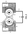
- FIG. 2 schematically shows a cross-sectional diagram according to one example of embodiment of the present gas discharge source, wherein only the two electrodes 1, the connecting elements, the reservoirs 15 and the capacitor bank 12 with the electrical feed lines 13 can be seen in the figure.
- the connecting elements are in each case designed as a metal block 14 with heating or cooling channels (not shown).
- the vacuum chamber and any screens are not shown and can be embodied in a manner already known from the aforementioned document.
- the two electrodes 1 are connected to the reservoirs 15 via the metal block 14, which is adapted to the circular periphery of the electrodes 1 in order to form a gap 19 between the block 14 and the electrodes 1.
- the reservoir 15 is integrated in the metal block 14.
- the liquid, electrically conductive material, which in the present example is liquid tin 5, is transported to the gap 19 via a feed channel 16.
- the tin, which has a melting point of 230°C, is kept at an operating temperature of for example 300°C in the reservoir 15.
- the tin is transported upwards in the gap 19 in the rotation direction, wherein excess tin flows back into the reservoir 15 at the upper end of the gap 19 via a return channel 17.
- the rotation of the electrodes 1 is indicated by the arrows.
- the gap 19 can have a constant thickness in the region of 1 mm between the feed channel 16 and the return channel 17, in order to keep to a minimum the friction forces between the electrode 1 and the block 14.
- the circulation of the liquid, electrically conductive material in the present gas discharge source may additionally be assisted by a pump.
- the inlet or outlet 20, 21 may also be specially shaped so that as uniform a thickness as possible of the tin film 22 on the surface of the electrodes is achieved and thus the tin film 22 is not stripped off and lost as it runs in.
- the thickness of the tin film 22 can be influenced via the configuration of the outlet 21, this being important for the process of producing radiation while at the same time minimizing the evaporated amount of tin per pulse. If some tin still exits from the narrow gap 19 between the electrode 1 and the metal block 14, this can be captured and transported back to the reservoir 15.
- the storage capacitors are directly connected to the metal block 14, as can be seen from Fig. 2 . In this way, an electrical connection with a low resistance is ensured via the liquid tin 5 to the electrodes 1.
- the source point 18 for the gas discharge is in the present example defined by the focal point of a laser beam (not shown). This corresponds to the mode of operation as has already been explained in connection with the gas discharge source described in the introduction.
- the tin is carried by the surface of the electrodes 1 in the rotation direction and stripped down again to a thin film 22 by the effect of the narrow gap 19 as said electrodes are rotated out.
- This carrying and stripping effect can be used for example for the targeted circulation of the liquid tin in the reservoir 15, as a result of which the dissipation of heat from the electrodes 1 to the tin and from the tin to the reservoir is improved.
- the dissipation of heat from the electrodes 1 to the tin bath in the region of the narrow gap 19 is much better than in the generic gas discharge source of Fig. 1 .
- a pump effect which is produced by the carrying of the tin into the gap 19 can also be used to continually purify the supply of tin.
- the return channel 17 shown in Fig. 2 through which the tin is pressed on account of the rotation of the electrodes 1 and the bottleneck effect caused by the narrowing of the gap 19 at the outlet 21, can also lead to the reservoir 15 via a diversion.
- the return channel can pass via a filter or in the simplest case an antechamber, which retain for example oxides which float on the tin.
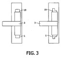
- Fig. 3 shows in section two differently configured disc-shaped electrodes 1, as can be used in the present gas discharge source.
- the figure shows a side view of the arrangement of metal block 14 and electrode 1 in cross section.
- the contour of the circular periphery of the electrode 1 may on the one hand be rectangular, as shown in the left-hand diagram. However, this is just one possible example. It may also be advantageous if the contour is stepped, as can be seen from the right-hand diagram.
- the opposite electrode is in this case manufactured in the manner of a mirror image, an interleaved discharge gap is produced in the arrangement shown in Fig. 2 .
- droplets of tin which may arise during the gas discharge are partially recaptured by the electrodes themselves and thus do not reach the walls or other regions within the vacuum chamber.
- the force of gravity may cause the liquid tin 5 for example to flow out of the gap 19 between the electrode 1 and the metal block 14.
- This can be counteracted in a contactless manner by means of magnetic forces.
- use is made of the fact that, due to the skin effect, alternating electromagnetic fields can produce eddy currents only in the thin tin layer. Said eddy currents, together with an applied magnetic field B, produce a Lorentz force which, given a suitable geometric configuration, counteracts the force of gravity.
- Such a magnetic force can also be used to control the thickness of the tin film 22 on the surface of the electrodes 1 and thus set an optimal value for plasma production.
- ferromagnetic materials can be incorporated both in certain regions of the electrodes and also the connecting elements or metal blocks.
- the magnetic field itself can be produced for example by means of coils and AC currents.
- Another possibility for preventing tin from flowing out of the gap 19 consists in adapting the filling level of the tin in the reservoirs 15 shown in Fig. 2 .
- the liquid level lies considerably above the lower region of the gap 19 in the region of the inlet 21 of the electrodes 1, so that the force of gravity exerts a certain pressure.
- the filling level can in principle also be lowered to the level of the inlet 21, so that the pressure difference disappears.
- Another possibility for preventing the tin from flowing out of the gap 19 consists in using materials with suitable surface properties.
- the surface of the electrodes 1 must be able to be wetted sufficiently in the region where the gas discharge takes place. If the surface of the metal block 14 cannot be wetted in the region which forms the surface of the gap 19 lying opposite the electrode 1, the capillary forces cannot prevent the tin from flowing out of the gap 19.
Claims (12)
- Gasentladungsquelle, insbesondere für EUV-Strahlung und/oder weiche Röntgenstrahlung, bei der in einer Vakuumkammer (2) mindestens zwei Elektroden (1) mit einem zumindest annähernd kreisförmigen Umfang zur Rotation drehbar gelagert sind, wobei die Elektroden (1) an einer Raumposition einen geringen Abstand für die Zündung einer Gasentladungslampe (6) aufweisen und jeweils mit einem Reservoir (15) für ein flüssiges, elektrisch leitfähiges Material (5) so in Verbindung stehen, dass sich während der Rotation über den kreisförmigen Umfang der Elektroden (1) ein Flüssigkeitsfilm (22) des elektrisch leitfähigen Materials (5) bilden kann und über die Reservoirs (15) ein Stromfluss zu den Elektroden (1) ermöglicht wird, wobei die Elektroden (1) jeweils über ein Verbindungselement (14) mit den Reservoirs (15) verbunden sind, durch welches über einen Teilabschnitt des kreisförmigen Umfangs jeder Elektrode (1) ein Spalt (19) zwischen der Elektrode (1) und dem Verbindungselement (14) gebildet wird, in den während der Rotation der Elektrode (1) das flüssige, elektrisch leitfähige Material (5) aus dem Reservoir (15) über mindestens einen in dem Verbindungselement (14) ausgebildeten Zulaufkanal (16) eindringen kann, dadurch gekennzeichnet, dass das Verbindungselement (14) so ausgebildet ist, dass sich der Spalt (19) in einer Rotationsrichtung der Elektrode (1) verjüngt.
- Gasentladungsquelle nach Anspruch 1, dadurch gekennzeichnet, dass das Verbindungselement (14) ebenfalls mindestens einen Rücklaufkanal (17) für das flüssige, elektrisch leitfähige Material (5) aufweist, wobei der Rücklaufkanal in den Spalt (19) mündet.
- Gasentladungsquelle nach Anspruch 2, dadurch gekennzeichnet, dass der Rücklaufkanal (17) über ein Reinigungsfilter oder eine Reinigungsvorkammer in das Reservoir (15) führt.
- Gasentladungsquelle nach einem der Ansprüche 1 bis 3, dadurch gekennzeichnet, dass der Spalt (19) so bemessen ist, dass das flüssige, elektrisch leitfähige Material (5) mit Hilfe von Kapillarkräften in den Spalt (19) gezogen und/oder in dem Spalt (19) gehalten wird.
- Gasentladungsquelle nach einem der Ansprüche 1 bis 4, dadurch gekennzeichnet, dass der Spalt (19) an den Enden desselben verjüngt ist.
- Gasentladungsquelle nach einem der Ansprüche 1 bis 5, dadurch gekennzeichnet, dass der Spalt (19) zumindest im Hinblick auf die Breite desselben so bemessen und geformt ist, dass der Flüssigkeitsfilm (22) des elektrisch leitfähigen Materials (5) im Bereich des geringen Abstands der Elektroden (1) eine Dicke aufweist, bei der eine für die Gasentladung (6) erforderliche, verdampfte Menge des elektrisch leitfähigen Materials (5) bei jedem Entladungsstoß minimiert wird.
- Gasentladungsquelle nach einem der Ansprüche 1 bis 6, dadurch gekennzeichnet, dass das Verbindungselement (14) weitere Kanäle aufweist, die von einer Temperaturregelungsflüssigkeit durchflossen werden können.
- Gasentladungsquelle nach einem der Ansprüche 1 bis 7, dadurch gekennzeichnet, dass die Elektroden (1) an dem kreisförmigen Umfang im Querschnitt senkrecht zu der Rotationsrichtung eine stufenförmige Kontur aufweisen, wobei die Konturen der beiden Elektroden (1) komplementär ausgebildet sind, so dass diese in dem Bereich des geringen Abstands ineinander greifen.
- Gasentladungsquelle nach einem der Ansprüche 1 bis 8, dadurch gekennzeichnet, dass eine magnetische Einrichtung vorgesehen ist, die verhindert, dass das elektrisch leitfähige Material (5) entgegen einer Rotationsrichtung der Elektrode (1) aus dem Spalt (19) ausfließt.
- Gasentladungsquelle nach Anspruch 9, dadurch gekennzeichnet, dass in Bereichen der Elektroden (1) und/oder Verbindungselemente (14) zur Verstärkung der Magnetkräfte der magnetischen Einrichtung ferromagnetische Materialien integriert sind.
- Gasentladungsquelle nach Anspruch 9 oder 10, dadurch gekennzeichnet, dass eine magnetische Einrichtung vorgesehen ist, um die Dicke des Flüssigkeitsfilms (22) des elektrisch leitfähigen Materials (5) über den zumindest annähernd kreisförmigen Umfang der Elektroden (1) zu steuern.
- Gasentladungsquelle nach einem der Ansprüche 1 bis 11, dadurch gekennzeichnet, dass die Vakuumkammer (2) eine Öffnung aufweist, welche die Zuführung energetischer Strahlung zur Verdampfung von Material des Flüssigkeitsfilms (22) im Bereich des geringen Abstands der Elektroden (1) ermöglicht.
Applications Claiming Priority (2)
| Application Number | Priority Date | Filing Date | Title |
|---|---|---|---|
| DE102005023060A DE102005023060B4 (de) | 2005-05-19 | 2005-05-19 | Gasentladungs-Strahlungsquelle, insbesondere für EUV-Strahlung |
| PCT/IB2006/051428 WO2006123270A2 (en) | 2005-05-19 | 2006-05-08 | Gas discharge source, in particular for euv radiation |
Publications (2)
| Publication Number | Publication Date |
|---|---|
| EP1886542A2 EP1886542A2 (de) | 2008-02-13 |
| EP1886542B1 true EP1886542B1 (de) | 2010-04-14 |
Family
ID=36933632
Family Applications (1)
| Application Number | Title | Priority Date | Filing Date |
|---|---|---|---|
| EP06744876A Active EP1886542B1 (de) | 2005-05-19 | 2006-05-08 | Gasentladungsquelle, insbesondere für euv-strahlung |
Country Status (8)
| Country | Link |
|---|---|
| US (1) | US7630475B2 (de) |
| EP (1) | EP1886542B1 (de) |
| JP (1) | JP4879974B2 (de) |
| KR (1) | KR101214136B1 (de) |
| CN (1) | CN101180923B (de) |
| AT (1) | ATE464776T1 (de) |
| DE (2) | DE102005023060B4 (de) |
| WO (1) | WO2006123270A2 (de) |
Families Citing this family (31)
| Publication number | Priority date | Publication date | Assignee | Title |
|---|---|---|---|---|
| US7759663B1 (en) * | 2006-12-06 | 2010-07-20 | Asml Netherlands B.V. | Self-shading electrodes for debris suppression in an EUV source |
| US7518134B2 (en) * | 2006-12-06 | 2009-04-14 | Asml Netherlands B.V. | Plasma radiation source for a lithographic apparatus |
| US7696493B2 (en) * | 2006-12-13 | 2010-04-13 | Asml Netherlands B.V. | Radiation system and lithographic apparatus |
| US7696492B2 (en) * | 2006-12-13 | 2010-04-13 | Asml Netherlands B.V. | Radiation system and lithographic apparatus |
| US7838853B2 (en) * | 2006-12-14 | 2010-11-23 | Asml Netherlands B.V. | Plasma radiation source, method of forming plasma radiation, apparatus for projecting a pattern from a patterning device onto a substrate and device manufacturing method |
| DE102007004440B4 (de) * | 2007-01-25 | 2011-05-12 | Xtreme Technologies Gmbh | Vorrichtung und Verfahren zur Erzeugung von extrem ultravioletter Strahlung mittels einer elektrisch betriebenen Gasentladung |
| JP5149514B2 (ja) * | 2007-02-20 | 2013-02-20 | ギガフォトン株式会社 | 極端紫外光源装置 |
| US20080239262A1 (en) * | 2007-03-29 | 2008-10-02 | Asml Netherlands B.V. | Radiation source for generating electromagnetic radiation and method for generating electromagnetic radiation |
| US7629593B2 (en) * | 2007-06-28 | 2009-12-08 | Asml Netherlands B.V. | Lithographic apparatus, radiation system, device manufacturing method, and radiation generating method |
| JP5709251B2 (ja) * | 2007-09-07 | 2015-04-30 | コーニンクレッカ フィリップス エヌ ヴェ | 高パワー動作のためのホイールカバーを有するガス放電光源のための回転ホイール電極 |
| EP2198675B1 (de) | 2007-09-07 | 2013-03-13 | Philips Intellectual Property & Standards GmbH | Elektrodenvorrichtung für gasentladungsquellen und verfahren zum betreiben einer gasentladungsquelle mit dieser elektrodenvorrichtung |
| WO2009044312A1 (en) * | 2007-10-01 | 2009-04-09 | Philips Intellectual Property & Standards Gmbh | High voltage electrical connection line |
| JP4952513B2 (ja) * | 2007-10-31 | 2012-06-13 | ウシオ電機株式会社 | 極端紫外光光源装置 |
| WO2009077943A1 (en) * | 2007-12-14 | 2009-06-25 | Philips Intellectual Property & Standards Gmbh | Method for laser-based plasma production and radiation source, in particular for euv radiation |
| DE102007060807B4 (de) | 2007-12-18 | 2009-11-26 | Fraunhofer-Gesellschaft zur Förderung der angewandten Forschung e.V. | Gasentladungsquelle, insbesondere für EUV-Strahlung |
| NL1036595A1 (nl) * | 2008-02-28 | 2009-08-31 | Asml Netherlands Bv | Device constructed and arranged to generate radiation, lithographic apparatus, and device manufacturing method. |
| KR101642269B1 (ko) | 2008-07-18 | 2016-07-26 | 코닌클리케 필립스 엔.브이. | 오염 포획자를 포함하는 극자외선 방사 발생 장치 |
| EP2170021B1 (de) | 2008-09-25 | 2015-11-04 | ASML Netherlands B.V. | Quellenmodul, Strahlungsquelle und Lithografievorrichtung |
| JP4623192B2 (ja) * | 2008-09-29 | 2011-02-02 | ウシオ電機株式会社 | 極端紫外光光源装置および極端紫外光発生方法 |
| JP5245857B2 (ja) * | 2009-01-21 | 2013-07-24 | ウシオ電機株式会社 | 極端紫外光光源装置 |
| JP5504673B2 (ja) * | 2009-03-30 | 2014-05-28 | ウシオ電機株式会社 | 極端紫外光光源装置 |
| EP2494854B1 (de) * | 2009-10-29 | 2013-06-19 | Koninklijke Philips Electronics N.V. | Elektrodensystem, im besonderen für gasentladungslichtquellen |
| EP2555598A1 (de) * | 2011-08-05 | 2013-02-06 | Fraunhofer-Gesellschaft zur Förderung der angewandten Forschung e.V. | Verfahren und Vorrichtung zur Erzeugung optischer Strahlung mithilfe elektrisch betätigter gepulster Entladungen |
| US20140247435A1 (en) * | 2011-11-15 | 2014-09-04 | Asml Netherlands B.V. | Radiation source device, lithographic apparatus, and device manufacturing method |
| DE102012109809B3 (de) * | 2012-10-15 | 2013-12-12 | Xtreme Technologies Gmbh | Vorrichtung zur Erzeugung von kurzwelliger elektromagnetischer Strahlung auf Basis eines Gasentladungsplasmas |
| DE102013103668B4 (de) | 2013-04-11 | 2016-02-25 | Ushio Denki Kabushiki Kaisha | Anordnung zum Handhaben eines flüssigen Metalls zur Kühlung von umlaufenden Komponenten einer Strahlungsquelle auf Basis eines strahlungsemittierenden Plasmas |
| DE102013109048A1 (de) * | 2013-08-21 | 2015-02-26 | Ushio Denki Kabushiki Kaisha | Verfahren und Vorrichtung zur Kühlung von Strahlungsquellen auf Basis eines Plasmas |
| DE102013017655B4 (de) | 2013-10-18 | 2017-01-05 | Ushio Denki Kabushiki Kaisha | Anordnung und Verfahren zum Kühlen einer plasmabasierten Strahlungsquelle |
| DE102014102720B4 (de) * | 2014-02-28 | 2017-03-23 | Ushio Denki Kabushiki Kaisha | Anordnung zum Kühlen einer plasmabasierten Strahlungsquelle mit einer metallischen Kühlflüssigkeit und Verfahren zur Inbetriebnahme einer solchen Kühlanordnung |
| US10021773B2 (en) | 2015-11-16 | 2018-07-10 | Kla-Tencor Corporation | Laser produced plasma light source having a target material coated on a cylindrically-symmetric element |
| CN113960019A (zh) * | 2021-10-26 | 2022-01-21 | 天津大学 | 一种双转盘电极原子发射光谱油液元素装置 |
Family Cites Families (8)
| Publication number | Priority date | Publication date | Assignee | Title |
|---|---|---|---|---|
| JP2000061839A (ja) * | 1998-08-19 | 2000-02-29 | Rikagaku Kenkyusho | マイクロ放電ツルーイング装置とこれを用いた微細加工方法 |
| TW589924B (en) * | 2001-04-06 | 2004-06-01 | Fraunhofer Ges Forschung | Process and device for producing extreme ultraviolet ray/weak x-ray |
| TWI266962B (en) * | 2002-09-19 | 2006-11-21 | Asml Netherlands Bv | Radiation source, lithographic apparatus, and device manufacturing method |
| EP1401248B1 (de) * | 2002-09-19 | 2012-07-25 | ASML Netherlands B.V. | Strahlungsquelle, Lithographiegerät und Methode zur Herstellung von Bauelementen |
| WO2004062050A2 (en) * | 2003-01-02 | 2004-07-22 | Jmar Research Inc. | Method and apparatus for generating a membrane target for laser produced plasma |
| DE10342239B4 (de) * | 2003-09-11 | 2018-06-07 | Fraunhofer-Gesellschaft zur Förderung der angewandten Forschung e.V. | Verfahren und Vorrichtung zum Erzeugen von Extrem-Ultraviolettstrahlung oder weicher Röntgenstrahlung |
| RU2278483C2 (ru) * | 2004-04-14 | 2006-06-20 | Владимир Михайлович Борисов | Эуф источник с вращающимися электродами и способ получения эуф излучения из газоразрядной плазмы |
| US7501642B2 (en) * | 2005-12-29 | 2009-03-10 | Asml Netherlands B.V. | Radiation source |
-
2005
- 2005-05-19 DE DE102005023060A patent/DE102005023060B4/de active Active
-
2006
- 2006-05-08 CN CN200680017282XA patent/CN101180923B/zh active Active
- 2006-05-08 DE DE602006013621T patent/DE602006013621D1/de active Active
- 2006-05-08 EP EP06744876A patent/EP1886542B1/de active Active
- 2006-05-08 WO PCT/IB2006/051428 patent/WO2006123270A2/en not_active Application Discontinuation
- 2006-05-08 US US11/914,773 patent/US7630475B2/en active Active
- 2006-05-08 KR KR1020077029674A patent/KR101214136B1/ko active IP Right Grant
- 2006-05-08 AT AT06744876T patent/ATE464776T1/de not_active IP Right Cessation
- 2006-05-08 JP JP2008511830A patent/JP4879974B2/ja active Active
Also Published As
| Publication number | Publication date |
|---|---|
| DE102005023060B4 (de) | 2011-01-27 |
| EP1886542A2 (de) | 2008-02-13 |
| KR20080043740A (ko) | 2008-05-19 |
| DE602006013621D1 (de) | 2010-05-27 |
| JP2008541472A (ja) | 2008-11-20 |
| KR101214136B1 (ko) | 2012-12-21 |
| US7630475B2 (en) | 2009-12-08 |
| JP4879974B2 (ja) | 2012-02-22 |
| WO2006123270A3 (en) | 2007-03-08 |
| CN101180923B (zh) | 2011-12-14 |
| ATE464776T1 (de) | 2010-04-15 |
| DE102005023060A1 (de) | 2006-11-30 |
| US20080187105A1 (en) | 2008-08-07 |
| CN101180923A (zh) | 2008-05-14 |
| WO2006123270A2 (en) | 2006-11-23 |
Similar Documents
| Publication | Publication Date | Title |
|---|---|---|
| EP1886542B1 (de) | Gasentladungsquelle, insbesondere für euv-strahlung | |
| US7622727B2 (en) | Extreme UV radiation source device | |
| EP1665907B1 (de) | Verfahren und vorrichtung zur herstellung von extrem-ultraviolettstrahlung oder weicher röntgenstrahlung | |
| JP5216772B2 (ja) | コンベアベルトターゲットを備えたeuvプラズマ放電ランプ | |
| EP1460886B1 (de) | Extrem-UV Strahlungsquelle und Halbleiterbelichtungsgerät | |
| KR101396158B1 (ko) | Euv 램프 및 연질 x-선 램프의 전환 효율을 증가시키는 방법, 및 euv 방사선 및 연질 x-선을 생성하는 장치 | |
| JP2004525844A (ja) | 負圧装置を用いてガラス溶融物を精製する方法及び装置 | |
| US7800086B2 (en) | Arrangement for radiation generation by means of a gas discharge | |
| JP2012516002A (ja) | X線窓 | |
| JP4763684B2 (ja) | 放射線源により生じる粒子の除去 | |
| JP2008544448A (ja) | Euv放射線及び/又は軟x線を発生させる放射線源を短絡から保護する方法 | |
| TWI445458B (zh) | 特別用於極紫外線輻射及/或軟x輻射的氣體放電源 | |
| EP1729550B1 (de) | Vorrichtung und Verfahren zum Schutz eines optischen Bauteils, inbesondere in einer EUV Quelle | |
| SE520087C2 (sv) | Förfarande och anordning för alstring av röntgen- eller EUV- strålning samt användning av den | |
| JP5503108B2 (ja) | 約1nmから約30nmの波長範囲の放射線を発生させる方法および機器、ならびにリソグラフィー装置 | |
| Vinokhodov et al. | High-brightness laser-induced EUV source based on tin plasma with an unlimited lifetime of electrodes | |
| JP6231141B2 (ja) | X線窓 | |
| JP5889968B2 (ja) | X線窓 | |
| WO2023148075A1 (en) | Assembly for a lithographic apparatus | |
| CN113711698A (zh) | 污染物陷阱 | |
| NL2021562A (en) | Apparatus for Receiving a Conductive Fuel |
Legal Events
| Date | Code | Title | Description |
|---|---|---|---|
| PUAI | Public reference made under article 153(3) epc to a published international application that has entered the european phase |
Free format text: ORIGINAL CODE: 0009012 |
|
| 17P | Request for examination filed |
Effective date: 20071219 |
|
| AK | Designated contracting states |
Kind code of ref document: A2 Designated state(s): AT BE BG CH CY CZ DE DK EE ES FI FR GB GR HU IE IS IT LI LT LU LV MC NL PL PT RO SE SI SK TR |
|
| 17Q | First examination report despatched |
Effective date: 20080326 |
|
| DAX | Request for extension of the european patent (deleted) | ||
| GRAP | Despatch of communication of intention to grant a patent |
Free format text: ORIGINAL CODE: EPIDOSNIGR1 |
|
| GRAS | Grant fee paid |
Free format text: ORIGINAL CODE: EPIDOSNIGR3 |
|
| GRAA | (expected) grant |
Free format text: ORIGINAL CODE: 0009210 |
|
| AK | Designated contracting states |
Kind code of ref document: B1 Designated state(s): AT BE BG CH CY CZ DE DK EE ES FI FR GB GR HU IE IS IT LI LT LU LV MC NL PL PT RO SE SI SK TR |
|
| REG | Reference to a national code |
Ref country code: GB Ref legal event code: FG4D |
|
| REG | Reference to a national code |
Ref country code: CH Ref legal event code: EP |
|
| REG | Reference to a national code |
Ref country code: IE Ref legal event code: FG4D |
|
| REF | Corresponds to: |
Ref document number: 602006013621 Country of ref document: DE Date of ref document: 20100527 Kind code of ref document: P |
|
| REG | Reference to a national code |
Ref country code: NL Ref legal event code: T3 |
|
| RAP2 | Party data changed (patent owner data changed or rights of a patent transferred) |
Owner name: FRAUNHOFER-GESELLSCHAFT ZUR FOERDERUNG DER ANGEWAN Owner name: PHILIPS INTELLECTUAL PROPERTY & STANDARDS GMBH Owner name: KONINKLIJKE PHILIPS ELECTRONICS N.V. |
|
| LTIE | Lt: invalidation of european patent or patent extension |
Effective date: 20100414 |
|
| PG25 | Lapsed in a contracting state [announced via postgrant information from national office to epo] |
Ref country code: ES Free format text: LAPSE BECAUSE OF FAILURE TO SUBMIT A TRANSLATION OF THE DESCRIPTION OR TO PAY THE FEE WITHIN THE PRESCRIBED TIME-LIMIT Effective date: 20100725 Ref country code: SE Free format text: LAPSE BECAUSE OF FAILURE TO SUBMIT A TRANSLATION OF THE DESCRIPTION OR TO PAY THE FEE WITHIN THE PRESCRIBED TIME-LIMIT Effective date: 20100414 Ref country code: LT Free format text: LAPSE BECAUSE OF FAILURE TO SUBMIT A TRANSLATION OF THE DESCRIPTION OR TO PAY THE FEE WITHIN THE PRESCRIBED TIME-LIMIT Effective date: 20100414 |
|
| PG25 | Lapsed in a contracting state [announced via postgrant information from national office to epo] |
Ref country code: IS Free format text: LAPSE BECAUSE OF FAILURE TO SUBMIT A TRANSLATION OF THE DESCRIPTION OR TO PAY THE FEE WITHIN THE PRESCRIBED TIME-LIMIT Effective date: 20100814 Ref country code: LV Free format text: LAPSE BECAUSE OF FAILURE TO SUBMIT A TRANSLATION OF THE DESCRIPTION OR TO PAY THE FEE WITHIN THE PRESCRIBED TIME-LIMIT Effective date: 20100414 Ref country code: SI Free format text: LAPSE BECAUSE OF FAILURE TO SUBMIT A TRANSLATION OF THE DESCRIPTION OR TO PAY THE FEE WITHIN THE PRESCRIBED TIME-LIMIT Effective date: 20100414 Ref country code: FI Free format text: LAPSE BECAUSE OF FAILURE TO SUBMIT A TRANSLATION OF THE DESCRIPTION OR TO PAY THE FEE WITHIN THE PRESCRIBED TIME-LIMIT Effective date: 20100414 Ref country code: AT Free format text: LAPSE BECAUSE OF FAILURE TO SUBMIT A TRANSLATION OF THE DESCRIPTION OR TO PAY THE FEE WITHIN THE PRESCRIBED TIME-LIMIT Effective date: 20100414 |
|
| PG25 | Lapsed in a contracting state [announced via postgrant information from national office to epo] |
Ref country code: GR Free format text: LAPSE BECAUSE OF FAILURE TO SUBMIT A TRANSLATION OF THE DESCRIPTION OR TO PAY THE FEE WITHIN THE PRESCRIBED TIME-LIMIT Effective date: 20100715 Ref country code: PL Free format text: LAPSE BECAUSE OF FAILURE TO SUBMIT A TRANSLATION OF THE DESCRIPTION OR TO PAY THE FEE WITHIN THE PRESCRIBED TIME-LIMIT Effective date: 20100414 Ref country code: MC Free format text: LAPSE BECAUSE OF NON-PAYMENT OF DUE FEES Effective date: 20100531 Ref country code: CY Free format text: LAPSE BECAUSE OF FAILURE TO SUBMIT A TRANSLATION OF THE DESCRIPTION OR TO PAY THE FEE WITHIN THE PRESCRIBED TIME-LIMIT Effective date: 20100519 |
|
| REG | Reference to a national code |
Ref country code: CH Ref legal event code: PL |
|
| PG25 | Lapsed in a contracting state [announced via postgrant information from national office to epo] |
Ref country code: PT Free format text: LAPSE BECAUSE OF FAILURE TO SUBMIT A TRANSLATION OF THE DESCRIPTION OR TO PAY THE FEE WITHIN THE PRESCRIBED TIME-LIMIT Effective date: 20100816 Ref country code: DK Free format text: LAPSE BECAUSE OF FAILURE TO SUBMIT A TRANSLATION OF THE DESCRIPTION OR TO PAY THE FEE WITHIN THE PRESCRIBED TIME-LIMIT Effective date: 20100414 Ref country code: EE Free format text: LAPSE BECAUSE OF FAILURE TO SUBMIT A TRANSLATION OF THE DESCRIPTION OR TO PAY THE FEE WITHIN THE PRESCRIBED TIME-LIMIT Effective date: 20100414 |
|
| PLBE | No opposition filed within time limit |
Free format text: ORIGINAL CODE: 0009261 |
|
| STAA | Information on the status of an ep patent application or granted ep patent |
Free format text: STATUS: NO OPPOSITION FILED WITHIN TIME LIMIT |
|
| PG25 | Lapsed in a contracting state [announced via postgrant information from national office to epo] |
Ref country code: CZ Free format text: LAPSE BECAUSE OF FAILURE TO SUBMIT A TRANSLATION OF THE DESCRIPTION OR TO PAY THE FEE WITHIN THE PRESCRIBED TIME-LIMIT Effective date: 20100414 Ref country code: SK Free format text: LAPSE BECAUSE OF FAILURE TO SUBMIT A TRANSLATION OF THE DESCRIPTION OR TO PAY THE FEE WITHIN THE PRESCRIBED TIME-LIMIT Effective date: 20100414 Ref country code: RO Free format text: LAPSE BECAUSE OF FAILURE TO SUBMIT A TRANSLATION OF THE DESCRIPTION OR TO PAY THE FEE WITHIN THE PRESCRIBED TIME-LIMIT Effective date: 20100414 Ref country code: CH Free format text: LAPSE BECAUSE OF NON-PAYMENT OF DUE FEES Effective date: 20100531 Ref country code: LI Free format text: LAPSE BECAUSE OF NON-PAYMENT OF DUE FEES Effective date: 20100531 |
|
| 26N | No opposition filed |
Effective date: 20110117 |
|
| GBPC | Gb: european patent ceased through non-payment of renewal fee |
Effective date: 20100714 |
|
| PG25 | Lapsed in a contracting state [announced via postgrant information from national office to epo] |
Ref country code: IT Free format text: LAPSE BECAUSE OF FAILURE TO SUBMIT A TRANSLATION OF THE DESCRIPTION OR TO PAY THE FEE WITHIN THE PRESCRIBED TIME-LIMIT Effective date: 20100414 |
|
| PG25 | Lapsed in a contracting state [announced via postgrant information from national office to epo] |
Ref country code: GB Free format text: LAPSE BECAUSE OF NON-PAYMENT OF DUE FEES Effective date: 20100714 |
|
| PG25 | Lapsed in a contracting state [announced via postgrant information from national office to epo] |
Ref country code: BG Free format text: LAPSE BECAUSE OF FAILURE TO SUBMIT A TRANSLATION OF THE DESCRIPTION OR TO PAY THE FEE WITHIN THE PRESCRIBED TIME-LIMIT Effective date: 20100414 Ref country code: HU Free format text: LAPSE BECAUSE OF FAILURE TO SUBMIT A TRANSLATION OF THE DESCRIPTION OR TO PAY THE FEE WITHIN THE PRESCRIBED TIME-LIMIT Effective date: 20101015 Ref country code: LU Free format text: LAPSE BECAUSE OF NON-PAYMENT OF DUE FEES Effective date: 20100508 |
|
| PG25 | Lapsed in a contracting state [announced via postgrant information from national office to epo] |
Ref country code: TR Free format text: LAPSE BECAUSE OF FAILURE TO SUBMIT A TRANSLATION OF THE DESCRIPTION OR TO PAY THE FEE WITHIN THE PRESCRIBED TIME-LIMIT Effective date: 20100414 |
|
| REG | Reference to a national code |
Ref country code: DE Ref legal event code: R081 Ref document number: 602006013621 Country of ref document: DE Owner name: PHILIPS INTELLECTUAL PROPERTY & STANDARDS GMBH, DE Free format text: FORMER OWNER: PHILIPS INTELLECTUAL PROPERTY & STANDARDS GMBH, 20099 HAMBURG, DE Effective date: 20121129 Ref country code: DE Ref legal event code: R081 Ref document number: 602006013621 Country of ref document: DE Owner name: FRAUNHOFER-GESELLSCHAFT ZUR FOERDERUNG DER ANG, DE Free format text: FORMER OWNER: PHILIPS INTELLECTUAL PROPERTY & STANDARDS GMBH, 20099 HAMBURG, DE Effective date: 20121129 Ref country code: DE Ref legal event code: R082 Ref document number: 602006013621 Country of ref document: DE Representative=s name: VOLMER, GEORG, DIPL.-ING., DE Effective date: 20121129 Ref country code: DE Ref legal event code: R081 Ref document number: 602006013621 Country of ref document: DE Owner name: PHILIPS DEUTSCHLAND GMBH, DE Free format text: FORMER OWNER: PHILIPS INTELLECTUAL PROPERTY & STANDARDS GMBH, 20099 HAMBURG, DE Effective date: 20121129 Ref country code: DE Ref legal event code: R081 Ref document number: 602006013621 Country of ref document: DE Owner name: PHILIPS GMBH, DE Free format text: FORMER OWNER: PHILIPS INTELLECTUAL PROPERTY & STANDARDS GMBH, 20099 HAMBURG, DE Effective date: 20121129 Ref country code: DE Ref legal event code: R082 Ref document number: 602006013621 Country of ref document: DE Representative=s name: MEISSNER BOLTE PATENTANWAELTE RECHTSANWAELTE P, DE Effective date: 20121129 |
|
| PG25 | Lapsed in a contracting state [announced via postgrant information from national office to epo] |
Ref country code: BG Free format text: LAPSE BECAUSE OF FAILURE TO SUBMIT A TRANSLATION OF THE DESCRIPTION OR TO PAY THE FEE WITHIN THE PRESCRIBED TIME-LIMIT Effective date: 20100714 |
|
| REG | Reference to a national code |
Ref country code: DE Ref legal event code: R082 Ref document number: 602006013621 Country of ref document: DE Representative=s name: VOLMER, GEORG, DIPL.-ING., DE |
|
| REG | Reference to a national code |
Ref country code: DE Ref legal event code: R081 Ref document number: 602006013621 Country of ref document: DE Owner name: PHILIPS GMBH, DE Free format text: FORMER OWNER: FRAUNHOFER-GESELLSCHAFT ZUR FOER, PHILIPS INTELLECTUAL PROPERTY &, , DE Effective date: 20140331 Ref country code: DE Ref legal event code: R081 Ref document number: 602006013621 Country of ref document: DE Owner name: PHILIPS GMBH, DE Free format text: FORMER OWNERS: FRAUNHOFER-GESELLSCHAFT ZUR FOERDERUNG DER ANGEWANDTEN FORSCHUNG E.V., 80686 MUENCHEN, DE; PHILIPS INTELLECTUAL PROPERTY & STANDARDS GMBH, 20099 HAMBURG, DE Effective date: 20140331 Ref country code: DE Ref legal event code: R081 Ref document number: 602006013621 Country of ref document: DE Owner name: FRAUNHOFER-GESELLSCHAFT ZUR FOERDERUNG DER ANG, DE Free format text: FORMER OWNERS: FRAUNHOFER-GESELLSCHAFT ZUR FOERDERUNG DER ANGEWANDTEN FORSCHUNG E.V., 80686 MUENCHEN, DE; PHILIPS INTELLECTUAL PROPERTY & STANDARDS GMBH, 20099 HAMBURG, DE Effective date: 20140331 Ref country code: DE Ref legal event code: R081 Ref document number: 602006013621 Country of ref document: DE Owner name: FRAUNHOFER-GESELLSCHAFT ZUR FOERDERUNG DER ANG, DE Free format text: FORMER OWNER: FRAUNHOFER-GESELLSCHAFT ZUR FOER, PHILIPS INTELLECTUAL PROPERTY &, , DE Effective date: 20140331 Ref country code: DE Ref legal event code: R082 Ref document number: 602006013621 Country of ref document: DE Representative=s name: VOLMER, GEORG, DIPL.-ING., DE Effective date: 20140331 Ref country code: DE Ref legal event code: R081 Ref document number: 602006013621 Country of ref document: DE Owner name: PHILIPS DEUTSCHLAND GMBH, DE Free format text: FORMER OWNER: FRAUNHOFER-GESELLSCHAFT ZUR FOER, PHILIPS INTELLECTUAL PROPERTY &, , DE Effective date: 20140331 Ref country code: DE Ref legal event code: R082 Ref document number: 602006013621 Country of ref document: DE Representative=s name: MEISSNER BOLTE PATENTANWAELTE RECHTSANWAELTE P, DE Effective date: 20140331 |
|
| REG | Reference to a national code |
Ref country code: FR Ref legal event code: CD Owner name: PHILIPS INTELLECTUAL PROPERTY & STANDARDS GMBH, DE Effective date: 20141126 Ref country code: FR Ref legal event code: CD Owner name: FRAUNHOFER-GESELLSCHAFT ZUR FORDERUNG DERANGEW, DE Effective date: 20141126 Ref country code: FR Ref legal event code: CA Effective date: 20141126 Ref country code: FR Ref legal event code: CD Owner name: KONINKLIJKE PHILIPS ELECTRONICS N.V., NL Effective date: 20141126 |
|
| REG | Reference to a national code |
Ref country code: DE Ref legal event code: R082 Ref document number: 602006013621 Country of ref document: DE Representative=s name: VOLMER, GEORG, DIPL.-ING., DE Ref country code: DE Ref legal event code: R081 Ref document number: 602006013621 Country of ref document: DE Owner name: FRAUNHOFER-GESELLSCHAFT ZUR FOERDERUNG DER ANG, DE Free format text: FORMER OWNER: FRAUNHOFER-GESELLSCHAFT ZUR FOER, PHILIPS DEUTSCHLAND GMBH, , DE Ref country code: DE Ref legal event code: R081 Ref document number: 602006013621 Country of ref document: DE Owner name: PHILIPS GMBH, DE Free format text: FORMER OWNER: FRAUNHOFER-GESELLSCHAFT ZUR FOER, PHILIPS DEUTSCHLAND GMBH, , DE Ref country code: DE Ref legal event code: R081 Ref document number: 602006013621 Country of ref document: DE Owner name: FRAUNHOFER-GESELLSCHAFT ZUR FOERDERUNG DER ANG, DE Free format text: FORMER OWNERS: FRAUNHOFER-GESELLSCHAFT ZUR FOERDERUNG DER ANGEWANDTEN FORSCHUNG E.V., 80686 MUENCHEN, DE; PHILIPS DEUTSCHLAND GMBH, 20099 HAMBURG, DE Ref country code: DE Ref legal event code: R081 Ref document number: 602006013621 Country of ref document: DE Owner name: PHILIPS GMBH, DE Free format text: FORMER OWNERS: FRAUNHOFER-GESELLSCHAFT ZUR FOERDERUNG DER ANGEWANDTEN FORSCHUNG E.V., 80686 MUENCHEN, DE; PHILIPS DEUTSCHLAND GMBH, 20099 HAMBURG, DE Ref country code: DE Ref legal event code: R082 Ref document number: 602006013621 Country of ref document: DE Representative=s name: MEISSNER BOLTE PATENTANWAELTE RECHTSANWAELTE P, DE |
|
| REG | Reference to a national code |
Ref country code: FR Ref legal event code: PLFP Year of fee payment: 11 |
|
| REG | Reference to a national code |
Ref country code: DE Ref legal event code: R082 Ref document number: 602006013621 Country of ref document: DE Representative=s name: MEISSNER BOLTE PATENTANWAELTE RECHTSANWAELTE P, DE |
|
| REG | Reference to a national code |
Ref country code: FR Ref legal event code: PLFP Year of fee payment: 12 |
|
| REG | Reference to a national code |
Ref country code: FR Ref legal event code: PLFP Year of fee payment: 13 |
|
| REG | Reference to a national code |
Ref country code: NL Ref legal event code: HC Owner name: KONINKLIJKE PHILIPS N.V.; NL Free format text: DETAILS ASSIGNMENT: CHANGE OF OWNER(S), CHANGE OF OWNER(S) NAME; FORMER OWNER NAME: KONINKLIJKE PHILIPS ELECTRONICS N.V. Effective date: 20191002 Ref country code: NL Ref legal event code: PD Owner name: USHIO DENKI KABUSHIKI KAISHA; JP Free format text: DETAILS ASSIGNMENT: CHANGE OF OWNER(S), ASSIGNMENT; FORMER OWNER NAME: KONINKLIJKE PHILIPS N.V. Effective date: 20191002 |
|
| REG | Reference to a national code |
Ref country code: BE Ref legal event code: PD Owner name: USHIO DENKI KABUSHIKI KAISHA; JP Free format text: DETAILS ASSIGNMENT: CHANGE OF OWNER(S), CESSION; FORMER OWNER NAME: KONINKLIJKE PHILIPS N.V. Effective date: 20191001 |
|
| REG | Reference to a national code |
Ref country code: DE Ref legal event code: R119 Ref document number: 602006013621 Country of ref document: DE |
|
| REG | Reference to a national code |
Ref country code: DE Ref legal event code: R073 Ref document number: 602006013621 Country of ref document: DE |
|
| PG25 | Lapsed in a contracting state [announced via postgrant information from national office to epo] |
Ref country code: DE Free format text: LAPSE BECAUSE OF NON-PAYMENT OF DUE FEES Effective date: 20191203 |
|
| REG | Reference to a national code |
Ref country code: DE Ref legal event code: R074 Ref document number: 602006013621 Country of ref document: DE |
|
| PG25 | Lapsed in a contracting state [announced via postgrant information from national office to epo] |
Ref country code: DE Free format text: LAPSE BECAUSE OF NON-PAYMENT OF DUE FEES Effective date: 20191203 |
|
| PGRI | Patent reinstated in contracting state [announced from national office to epo] |
Ref country code: DE Effective date: 20200513 |
|
| REG | Reference to a national code |
Ref country code: DE Ref legal event code: R082 Ref document number: 602006013621 Country of ref document: DE Representative=s name: MEISSNER BOLTE PATENTANWAELTE RECHTSANWAELTE P, DE Ref country code: DE Ref legal event code: R081 Ref document number: 602006013621 Country of ref document: DE Owner name: PHILIPS GMBH, DE Free format text: FORMER OWNERS: FRAUNHOFER-GESELLSCHAFT ZUR FOERDERUNG DER ANGEWANDTEN FORSCHUNG E.V., 80686 MUENCHEN, DE; PHILIPS GMBH, 20099 HAMBURG, DE Ref country code: DE Ref legal event code: R081 Ref document number: 602006013621 Country of ref document: DE Owner name: FRAUNHOFER-GESELLSCHAFT ZUR FOERDERUNG DER ANG, DE Free format text: FORMER OWNERS: FRAUNHOFER-GESELLSCHAFT ZUR FOERDERUNG DER ANGEWANDTEN FORSCHUNG E.V., 80686 MUENCHEN, DE; PHILIPS GMBH, 20099 HAMBURG, DE |
|
| REG | Reference to a national code |
Ref country code: FR Ref legal event code: PLFP Year of fee payment: 18 |
|
| PGFP | Annual fee paid to national office [announced via postgrant information from national office to epo] |
Ref country code: NL Payment date: 20230417 Year of fee payment: 18 |
|
| PGFP | Annual fee paid to national office [announced via postgrant information from national office to epo] |
Ref country code: IE Payment date: 20230412 Year of fee payment: 18 Ref country code: FR Payment date: 20230411 Year of fee payment: 18 Ref country code: DE Payment date: 20220628 Year of fee payment: 18 |
|
| PGFP | Annual fee paid to national office [announced via postgrant information from national office to epo] |
Ref country code: BE Payment date: 20230418 Year of fee payment: 18 |