EP2198675B1 - Elektrodenvorrichtung für gasentladungsquellen und verfahren zum betreiben einer gasentladungsquelle mit dieser elektrodenvorrichtung - Google Patents
Elektrodenvorrichtung für gasentladungsquellen und verfahren zum betreiben einer gasentladungsquelle mit dieser elektrodenvorrichtung Download PDFInfo
- Publication number
- EP2198675B1 EP2198675B1 EP08807513A EP08807513A EP2198675B1 EP 2198675 B1 EP2198675 B1 EP 2198675B1 EP 08807513 A EP08807513 A EP 08807513A EP 08807513 A EP08807513 A EP 08807513A EP 2198675 B1 EP2198675 B1 EP 2198675B1
- Authority
- EP
- European Patent Office
- Prior art keywords
- circumferential surface
- outer circumferential
- electrode
- electrode wheel
- wiper
- Prior art date
- Legal status (The legal status is an assumption and is not a legal conclusion. Google has not performed a legal analysis and makes no representation as to the accuracy of the status listed.)
- Active
Links
Images



Classifications
-
- H—ELECTRICITY
- H05—ELECTRIC TECHNIQUES NOT OTHERWISE PROVIDED FOR
- H05G—X-RAY TECHNIQUE
- H05G2/00—Apparatus or processes specially adapted for producing X-rays, not involving X-ray tubes, e.g. involving generation of a plasma
- H05G2/001—Production of X-ray radiation generated from plasma
- H05G2/002—Supply of the plasma generating material
Definitions
- the present invention relates to an electrode device for gas discharge sources at least comprising an electrode wheel rotatable around a rotational axis, said electrode wheel having an outer circumferential surface between two side surfaces, and a wiper unit arranged to limit the thickness of a liquid material film applied to at least a portion of said outer circumferential surface during rotation of said electrode wheel.
- the invention further relates to a gas discharge source comprising such an electrode device and to a method of operating the gas discharge source with this electrode device.
- Gas discharge sources are used, for example, as light sources for EUV radiation (EUV: extreme ultra violet) or soft x-rays.
- EUV radiation extreme ultra violet
- Radiation sources emitting EUV radiation and/or soft x-rays are in particular required in the field of EUV lithography.
- the radiation is emitted from hot plasma produced by a pulsed current.
- the most powerful EUV radiation sources known up to now are operated with metal vapor to generate the required plasma.
- An example of such a EUV radiation source is shown in WO 2005/025280 A2 .
- the metal vapor is produced from a metal melt which is applied to a surface in the discharge space and at least partially evaporated by an energy beam, in particular by a laser beam.
- the two electrodes are rotatably mounted forming electrode wheels which are rotated during operation of the radiation source.
- the electrode wheels dip during rotation into containers with the metal melt.
- a pulsed laser beam is directed directly to the surface of one of the electrodes in the discharge region in order to generate the metal vapor from the adhered metal melt and ignite the electrical discharge.
- the metal vapor is heated by a current of some kA up to some 10 kA so that the desired ionization stages are excited and light of the desired wavelength is emitted.
- the liquid metal film formed on the outer circumferential surfaces of the electrode wheels serves as the radiating medium in the discharge and protects as a regenerative film the wheel from erosion.
- WO 2005/025280 A2 discloses the use of strippers or wipers in order to ensure a limited thickness of the liquid material film applied to the outer circumferential surface of the electrode wheels. Nevertheless, the rotational frequency of the electrode wheels is limited due to the formation of droplets or instabilities of the liquid metal film at higher rotational speeds.
- the proposed electrode device at least comprises an electrode wheel rotatable around a rotational axis, said electrode wheel having an outer circumferential surface between two side surfaces, and a wiper unit arranged to limit the thickness of a liquid material film applied to at least a portion of said outer circumferential surface during rotation of said electrode wheel.
- the wiper unit is arranged and designed to form a gap between said outer circumferential surface and a wiping edge of the wiper unit and to inhibit or at least reduce a migration of liquid material from said side surfaces to the circumferential surface during rotation of the electrode wheel.
- the electrode wheel of such an electrode device compared to the known electrode device disclosed in WO 2005/025280 A2 , can be rotated at higher rotational speeds due to the wiper unit which inhibits or at least reduces a flow of liquid material from the side surfaces of the wheel to the outer circumferential surface.
- Such a measure is not realized with the wiper of WO 2005/025280 A2 , which only controls the film thickness on the outer circumferential surface.
- the reduction of this flow or migration allows an improved control of the total amount of liquid material on the outer circumferential surface of the wheel and its distribution on this surface. Therefore, the thickness of the liquid material film on the rotating electrode wheel can be effectively limited even at higher rotational speeds to form a stable film which is maintained with sufficient thickness at the discharge region.
- higher rotational speeds are achieved compared to electrode devices which do not have such a wiper unit suppressing or reducing the migration of liquid material from the side surfaces to the outer circumferential surface and reducing the amount of liquid metal on the circumferential surface.
- a gas discharge source preferably comprises two electrodes which are arranged to have a smallest distance at the discharge region, a power supply for applying high voltage between the two electrodes and a device for applying the liquid material film on at least a portion of the outer circumferential surface of the electrode wheel.
- the material may be applied as a solid material on the outer circumferential surface of the electrode wheel and then heated to form a liquid material film on at least a portion of this outer circumferential surface.
- both electrodes are electrode wheels with the corresponding wiper units according to the proposed electrode device.
- the wiper unit may be formed of one single wiper element or of several wiper elements acting together.
- the single wiper element or wiper elements are preferably arranged and designed to strip off liquid material at portions of said side surfaces adjacent to the circumferential surface during rotation of said electrode wheel.
- the corresponding wiper element may be formed to have a fork-like shape at the portion facing the circumferential surface of the electrode wheel.
- the wiper element defines a gap between the circumferential surface and a wiping edge of the wiper element which gap is closed on both sides by the side pieces of the wiper element touching or nearly touching the side surfaces of the electrode wheel. This gap between the circumferential surface and a wiping edge of the wiper element is necessary in order to limit the thickness of the liquid material film to a desired height.
- the outer circumferential surface of the electrode wheel can have a planar shape or a curved shape over its width.
- the outer circumferential surface may also comprise a groove extending in the circumferential direction of the electrode wheel.
- the outer circumferential surface has a planar shape over its width and the wiper unit at the same time is designed to form a gap of a constant thickness over this width of the outer circumferential surface.
- one of the wiper elements is designed to form the gap and at the same time to strip off liquid material from the side surfaces of the electrode wheel
- one of the wiper elements to form the gap and one or several further wiper elements to strip off liquid material at portions of the side surfaces of the electrode wheel.
- several wiper units may be arranged at different positions of the circumferential surface with respect to the rotational direction in order to further improve the shaping of the liquid material film on the circumferential surface.
- a further wiper unit is designed similar to the main wiper unit, having one or several wiper elements limiting the thickness of the liquid material film on the surfaces of the wheel. Said further wiper unit is then arranged in a rotational direction before said main wiper unit.
- Preferably further measures are taken to reduce the amount of liquid material which may migrate during rotation of the electrode wheel from the side surfaces to the circumferential surface.
- One of these measures is to use an electrode wheel which has a T-shaped cross section at the outer circumferential surface. Due to this T-shaped form the liquid material can not access the outer circumferential surface on a straight way but has to move around a protrusion.
- a further preferable measure is to apply a non-wetting layer or coating on the side surfaces of the electrode wheel. It goes without saying that the outer circumferential surface on the other hand must consist of a wetting material or be coated with such a material.
- the liquid material film is subject to centrifugal, viscous and surface tension forces which influence the film thickness profile dynamically and can lead to formation of liquid material droplets.
- centrifugal, viscous and surface tension forces which influence the film thickness profile dynamically and can lead to formation of liquid material droplets.
- the distance of the wiping edge defining this gap and the outer circumferential surface of the electrode wheel is preferable adjustable by using an adjustable wiper element. This allows the proper setting of the gap dependent on the rotational frequency and the properties of the liquid material used when operating the gas discharge source.
- the gap must be chosen large enough, such that enough liquid material is available to ensure the required film thickness of the order of several tens of micrometers at the discharge location.
- the area of the gap is therefore controlled to fulfill the above equation.
- the constant thickness of the gap is controlled automatically by an appropriate sensor and an appropriate control unit during operation of the gas discharge source.
- an electrode wheel having an outer circumferential surface which has a cross section of rectangular shape or at least has a rectangular shape at a portion of the cross sectional profile.
- the wiper can be pressed on the wheel surface by an elastic element like a spring resulting in an effect like with a hydrodynamic bearing.
- a definite film thickness is achieved dependent on the rotational speed and the elastic force pressing the wiper element against the surface.
- the gap thickness and thus the thickness of the liquid material layer can be controlled, for example by rolling elements on the wiper unit, which define the distance of the wiper element to the outer circumferential surface of the electrode wheel.
- FIG. 1 shows a schematic side view of a pulsed gas discharge source, in which an electrode device according to the present invention may be implemented. Details of this electrode device are not shown in the figure.
- the gas discharge source comprises the two electrodes 1, 2 arranged in a discharge space of pre-definable gas pressure.
- the wheel shaped electrodes 1, 2 are rotatable mounted, i.e. they are rotated during operation about a rotational axis 3.
- the electrodes 1, 2 partially dip into corresponding containers 4, 5.
- Each of these containers 4, 5 contains a metal melt 6, in the present case liquid tin.
- the metal melt 6 is kept on a temperature of approximately 300° C, i.e. slightly above the melting point of 230° C of tin.
- the metal melt in the containers 4, 5 is maintained at the above operation temperature by a heating device or a cooling device (not shown in the figure) connected to said containers.
- a heating device or a cooling device (not shown in the figure) connected to said containers.
- the outer circumferential surfaces of the electrodes 1, 2 are wetted by the liquid metal so that a liquid metal film forms on said electrodes.
- the layer thickness of the liquid metal film on the outer circumferential surface of the electrodes 1, 2 is controlled by a wiper unit 11 only schematically indicated in Figure 1 . Examples of this wiper unit 11 are shown in Figures 3 to 7 .
- the current to the electrodes 1, 2 is supplied via metal melt 6, which is connected to the capacitor bank 7 via an insulated feed through 8.
- a pulsed laser beam 9 is focused on one of the electrodes 1, 2 at the narrowest point between the two electrodes.
- part of the metal film located on the electrodes 1, 2 evaporates and bridges over the electrode gap. This leads to the ignition of an electrical discharge at this point and a very fast current rise powered by the capacitor bank 7.
- the high current heats the metal vapor or fuel to such high temperatures that the latter is ionized and emits the desired EUV radiation in a pinch plasma 15.
- a debris mitigation unit 10 is arranged in front of the gas discharge source. This debris mitigation unit 10 allows the straight pass of radiation out of the gas discharge source but retains a high amount of debris particles on their way out.
- a screen 12 may be arranged between the electrodes 1, 2 and the housing.
- a metal shield 13 is arranged inside the gap between the two containers 4, 5 in order to reduce the diffusion of fuel into this gap.
- FIG 2 shows a schematic side view of the electrode wheel 1 of Figure 1 .
- the rotating wheel I is in contact with a liquid metal supply 14 formed by container 5 in Figure 1 , in which the wheel is partially submersed.
- the liquid metal film forming on the outer circumferential surface of electrode wheel 1 is first shaped by an optional pre-wiper 16 and then by a main wiper 11 as indicated in Figure 2 .
- the shapes of the circumferential surface of electrode wheel 1 and of the wiping edges of wipers 11, 16 are chosen such that an optimal liquid metal film thickness profile is achieved at the discharge location with the required rotational frequency of the electrode wheel 1.
- the wiper (s) By appropriately shaping and positioning the wiper (s) in combination with an adequately designed electrode wheel surface the liquid metal film can be controlled to remain stable at highest rotational frequencies and/or to concentrate at a required location on the outer circumferential surface of the electrode wheel. Examples for appropriate shapes are shown in Figures 3 to 7 .
- a main feature of the present invention is the design of wiper unit 11 which is the wiper unit closest to the discharge location with respect to the rotational movement of the electrode wheel 1.
- This wiper unit 11 is designed to inhibit or at least reduce the flow of liquid metal from the side surfaces of the electrode wheel to the outer circumferential surface during rotation of the wheel.
- the wiper unit 11 can be formed of one single wiper element having a fork-like shape as shown in Figure 3 . With such a wiper unit 11a defined gap 17 is formed between the outer circumferential surface 18 of the electrode wheel 1 and an opposed wiping edge 19 of the wiper element. At the same time liquid material on the side surfaces 26 and 27 of the electrode wheel 1 is stripped off by side pieces 20 of the wiper element and can not flow onto the outer circumferential surface 18 of the electrode wheel.
- Figure 4 shows a further exemplary embodiment in which in addition to the fork-like shape of the wiper unit 11, the electrode wheel 1 is formed to have a groove 21 extending around its outer circumferential surface.
- the gap 17 between the wiping edge 19 of wiper unit 11 and the outer circumferential surface 18 of the electrode wheel 1 is defined by the depth of the groove 21.
- Figure 4 also indicates a non-wetting coating 25 on the side surfaces of the electrode wheel 1, which avoids the formation of a larger amount of liquid material on these side surfaces during rotation.
- the electrode wheel may have a T-shaped cross section at the outer circumferential surface as shown in Figure 5 .
- This T-shaped form additionally constricts the migration of liquid material from the side surfaces to the outer circumferential surface.
- the wiper unit 11 is composed of three wiper elements 22, 23, 24.
- First wiper element 22 defines the gap 17 between the outer circumferential surface 18 and wiping edge 19.
- Second and third wiper element 23 and 24 strip off liquid material from the side surfaces of the electrode wheel.
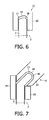
- Figures 3 to 5 have shown gaps between the outer circumferential surface of the electrode wheel and the corresponding wiping edge of wiper unit 11 which have a rectangular cross section. Nevertheless, other wheel shapes at the outer circumferential surface of the electrode wheel in connection with correspondingly adapted designs of the wiper unit may be used if the discharge location and hence the maximum film thickness is intended to be off the middle of the outer circumferential surface of the electrode wheel. Examples for such geometries are shown in Figures 6 and 7 . With both geometries of the electrode wheel and the wiper unit the liquid material will accumulate off center with respect to the rotation plane of the electrode wheel. In Figure 6 , the wiper unit 11 is formed of one single wiper element, whereas in Figure 7 , different wiper elements 22, 23, 24 form wiper unit 11.
- Figures 8 and 9 show a comparison of the dependence of film thickness at the discharge location from the rotational frequency of the electrode wheel between a discharge gas source according to the prior art which did not comprise any wiper and a discharge gas source according to the present invention.
- the discharge gas source of the present invention used a wiper unit according to Figure 3 .
- the film thickness of the liquid metal film in a system according to prior art significantly increases with increasing rotational speed to up to 700 ⁇ m.
- Droplets are formed at rotational speeds of more than 12 Hz.
- the film thickness of a discharge source according to the present invention remains in a thickness range between 50 and 100 ⁇ m over a wide range of rotational frequencies up to 18 Hz.
- the formation of droplets begins at frequencies greater than 18 Hz. This means that the maximum rotational frequency could be increased by using an electrode device with the appropriate wiper unit according to the present invention from 12 Hz to 18 Hz.
- significant increase of repetition rate of the discharge at stable lamp operation are achieved, resulting in higher output power of the lamp.
Landscapes
- Physics & Mathematics (AREA)
- Engineering & Computer Science (AREA)
- Optics & Photonics (AREA)
- Plasma & Fusion (AREA)
- Plasma Technology (AREA)
- X-Ray Techniques (AREA)
- Physical Or Chemical Processes And Apparatus (AREA)
Claims (15)
- Elektrodenvorrichtung für Gasentladungsquellen, die zumindest Folgendes umfasst:- eine Radelektrode (1), die sich um eine Drehachse (3) drehen kann, wobei die genannte Radelektrode (1) eine äußere Umfangsfläche (18) zwischen zwei Seitenflächen (26, 27) aufweist, und- einen Abstreifer (11), der für die Begrenzung der Dicke eines flüssigen Materialfilms ausgelegt ist, der während der Drehung der genannten Radelektrode (1) auf zumindest ein Teilstück der genannten äußeren Umfangsfläche (18) und der genannten Seitenflächen (26, 27) aufgebracht wird,wobei der genannte Abstreifer (11) für die Bildung eines Spaltes (17) zwischen der genannten äußeren Umfangsfläche (18) und einer Abstreifkante (19) des Abstreifers (11) angeordnet und ausgelegt ist,
dadurch gekennzeichnet, dass der genannte Abstreifer für die Verhinderung oder zumindest Reduzierung des Übergangs von flüssigem Material von den genannten Seitenflächen (26, 27) auf die genannte äußere Umfangsfläche (18) während der Drehung der genannten Radelektrode (1) ausgelegt ist. - Vorrichtung nach Anspruch 1,
wobei der genannte Abstreifer (11) für das Abstreifen von flüssigem Material an Teilstücken der genannten an die äußeren Umfangsfläche (18) angrenzenden Seitenflächen (26, 27) während der Drehung der genannten Radelektrode (1) angeordnet und ausgelegt ist. - Vorrichtung nach Anspruch 2,
wobei der genannte Abstreifer (11) ein gabelförmiges Abstreifelement umfasst. - Vorrichtung nach Anspruch 2 oder 3,
wobei der genannte Abstreifer (11) mehrere zusammenwirkende Abstreifelemente (22, 23, 24) umfasst. - Vorrichtung nach Anspruch 4,
wobei eines der genannten Abstreifelemente (22, 23, 24) für die Bildung des genannten Spaltes (17) angeordnet und ausgelegt ist und eines oder mehrere weitere der genannten Abstreifelemente (22, 23, 24) für das Abstreifen von flüssigem Material an Teilstücken der genannten Seitenflächen (26, 27) der Radelektrode (1) angeordnet und ausgelegt ist/sind. - Vorrichtung nach Anspruch 1,
wobei die genannte Radelektrode (1) an der äußeren Umfangsfläche (18) einen T-förmigen Querschnitt aufweist. - Vorrichtung nach Anspruch 1,
wobei die genannte äußere Umfangsfläche (18) eine Nut (21) bildet, die in Umfangsrichtung verläuft. - Vorrichtung nach Anspruch 1,
wobei der genannte Abstreifer (11) für die Bildung des genannten Spaltes (17) mit einer konstanten Dicke über die Breite der genannten äußeren Umfangsfläche (18) ausgelegt ist. - Vorrichtung nach Anspruch 1,
wobei die genannten Seitenflächen (26, 27) mit einem nicht benetzenden Material oder einer entsprechenden Beschichtung (25) bedeckt sind. - Vorrichtung nach Anspruch 1,
wobei der Abstreifer (11) so ausgelegt ist, dass er eine Anpassung der Breite des Spaltes (17), der durch den Abstand zwischen der äußeren Umfangsfläche (18) und der Abstreifkante (19) bestimmt wird, bei unterschiedlichen Drehfrequenzen der Radelektrode (1) gestattet. - Vorrichtung nach Anspruch 1,
wobei ein weiterer Abstreifer (16) in Drehrichtung vor dem genannten Abstreifer (11) angeordnet ist, wobei der weitere Abstreifer (16) für die Begrenzung der Dicke des flüssigen Materialfilms auf der äußeren Umfangsfläche (18) ausgelegt ist. - Gasentladungsquelle, die die Elektrodenvorrichtung nach Anspruch 1 umfasst, wobei die Radelektrode (1) der genannten Elektrodenvorrichtung eine erste von zwei Elektroden (1, 2) der genannten Gasentladungsquelle bildet, die so ausgelegt sind, dass sie einen geringsten Abstand in einer Entladungsregion haben, wobei die Gasentladungsquelle ferner eine Vorrichtung (4, 5) zum Aufbringen oder Erzeugen eines flüssigen Materialfilms auf zumindest ein Teilstück der äußeren Umfangsfläche (18) der Radelektrode (1) umfasst.
- Gasentladungsquelle nach Anspruch 12, wobei die beiden Elektroden (1, 2) von einer Elektrodenvorrichtung nach Anspruch 1 gebildet werden.
- Verfahren zum Betreiben einer Gasentladungsquelle nach Anspruch 12, wobei die Radelektrode (1) mit einer Winkeldrehfrequenz von • = 2• f angetrieben wird und wobei der Abstand des Abstreifers (11) zur äußeren Umfangsfläche (18) der Radelektrode (1) so angepasst wird, dass er den Spalt (17) mit einer Spaltfläche A bildet, die eine maximale Spaltfläche Amax = 8• / (•• 2R) nicht überschreitet, wobei • eine Oberflächenspannung des aufgebrachten flüssigen Materials, • eine Dichte des aufgebrachten flüssigen Materials und R ein Radradius der Radelektrode (1) ist, der als der Abstand der Umfangsfläche (18) zu der Drehachse (3) des Rades definiert ist.
- Verfahren nach Anspruch 14,
wobei die Radelektrode (1) so dimensioniert ist, dass sie an ihrer äußeren Umfangsfläche (18) eine Breite D hat, wobei D* < D < 10·D* und
Priority Applications (1)
| Application Number | Priority Date | Filing Date | Title |
|---|---|---|---|
| EP08807513A EP2198675B1 (de) | 2007-09-07 | 2008-09-03 | Elektrodenvorrichtung für gasentladungsquellen und verfahren zum betreiben einer gasentladungsquelle mit dieser elektrodenvorrichtung |
Applications Claiming Priority (3)
| Application Number | Priority Date | Filing Date | Title |
|---|---|---|---|
| EP07115920 | 2007-09-07 | ||
| EP08807513A EP2198675B1 (de) | 2007-09-07 | 2008-09-03 | Elektrodenvorrichtung für gasentladungsquellen und verfahren zum betreiben einer gasentladungsquelle mit dieser elektrodenvorrichtung |
| PCT/IB2008/053560 WO2009031104A1 (en) | 2007-09-07 | 2008-09-03 | Electrode device for gas discharge sources and method of operating a gas discharge source having this electrode device |
Publications (2)
| Publication Number | Publication Date |
|---|---|
| EP2198675A1 EP2198675A1 (de) | 2010-06-23 |
| EP2198675B1 true EP2198675B1 (de) | 2013-03-13 |
Family
ID=40149644
Family Applications (1)
| Application Number | Title | Priority Date | Filing Date |
|---|---|---|---|
| EP08807513A Active EP2198675B1 (de) | 2007-09-07 | 2008-09-03 | Elektrodenvorrichtung für gasentladungsquellen und verfahren zum betreiben einer gasentladungsquelle mit dieser elektrodenvorrichtung |
Country Status (7)
| Country | Link |
|---|---|
| US (1) | US8040033B2 (de) |
| EP (1) | EP2198675B1 (de) |
| JP (1) | JP4949516B2 (de) |
| KR (1) | KR101477472B1 (de) |
| CN (1) | CN101796893B (de) |
| TW (1) | TWI459863B (de) |
| WO (1) | WO2009031104A1 (de) |
Families Citing this family (13)
| Publication number | Priority date | Publication date | Assignee | Title |
|---|---|---|---|---|
| JP5709251B2 (ja) * | 2007-09-07 | 2015-04-30 | コーニンクレッカ フィリップス エヌ ヴェ | 高パワー動作のためのホイールカバーを有するガス放電光源のための回転ホイール電極 |
| EP2380411B1 (de) * | 2008-12-16 | 2015-04-15 | Philips Deutschland GmbH | Verfahren und einrichtung zum erzeugen von euv-strahlung oder weichen röntgenstrahlen mit erhöhtem wirkungsgrad |
| JP5504673B2 (ja) * | 2009-03-30 | 2014-05-28 | ウシオ電機株式会社 | 極端紫外光光源装置 |
| EP2555598A1 (de) * | 2011-08-05 | 2013-02-06 | Fraunhofer-Gesellschaft zur Förderung der angewandten Forschung e.V. | Verfahren und Vorrichtung zur Erzeugung optischer Strahlung mithilfe elektrisch betätigter gepulster Entladungen |
| TWI596384B (zh) * | 2012-01-18 | 2017-08-21 | Asml荷蘭公司 | 光源收集器元件、微影裝置及元件製造方法 |
| DE102012109809B3 (de) * | 2012-10-15 | 2013-12-12 | Xtreme Technologies Gmbh | Vorrichtung zur Erzeugung von kurzwelliger elektromagnetischer Strahlung auf Basis eines Gasentladungsplasmas |
| JP5724986B2 (ja) * | 2012-10-30 | 2015-05-27 | ウシオ電機株式会社 | 放電電極 |
| EP2816876B1 (de) * | 2013-06-21 | 2016-02-03 | Ushio Denki Kabushiki Kaisha | EUV-Entladungslampe mit beweglicher Schutzkomponente |
| DE102013110760B4 (de) | 2013-09-27 | 2017-01-12 | Ushio Denki Kabushiki Kaisha | Strahlungsquelle zur Erzeugung von kurzwelliger Strahlung aus einem Plasma |
| JP2016195035A (ja) | 2015-03-31 | 2016-11-17 | ウシオ電機株式会社 | 極端紫外光光源装置 |
| JP6477179B2 (ja) * | 2015-04-07 | 2019-03-06 | ウシオ電機株式会社 | 放電電極及び極端紫外光光源装置 |
| JP2023149176A (ja) * | 2022-03-30 | 2023-10-13 | ウシオ電機株式会社 | 光源装置 |
| JP2024179110A (ja) * | 2023-06-14 | 2024-12-26 | ウシオ電機株式会社 | 光源装置及び膜厚調整機構 |
Family Cites Families (12)
| Publication number | Priority date | Publication date | Assignee | Title |
|---|---|---|---|---|
| KR880000215A (ko) * | 1986-06-10 | 1988-03-24 | 나까므라 히사오 | 시이트(sheet)상 물체의 플라즈마 처리장치 |
| JPH01137543A (ja) * | 1987-11-24 | 1989-05-30 | Fujitsu Ltd | レーザ励起x線発生装置 |
| JP4068283B2 (ja) * | 1999-04-30 | 2008-03-26 | 有限会社サイファー社 | レーザプラズマx線発生装置 |
| JP4351413B2 (ja) * | 2002-03-05 | 2009-10-28 | 望月 孝晏 | レーザプラズマx線発生装置 |
| DE10342239B4 (de) * | 2003-09-11 | 2018-06-07 | Fraunhofer-Gesellschaft zur Förderung der angewandten Forschung e.V. | Verfahren und Vorrichtung zum Erzeugen von Extrem-Ultraviolettstrahlung oder weicher Röntgenstrahlung |
| FR2882886B1 (fr) * | 2005-03-02 | 2007-11-23 | Commissariat Energie Atomique | Source monochromatique de rayons x et microscope a rayons x mettant en oeuvre une telle source |
| DE102005023060B4 (de) | 2005-05-19 | 2011-01-27 | Fraunhofer-Gesellschaft zur Förderung der angewandten Forschung e.V. | Gasentladungs-Strahlungsquelle, insbesondere für EUV-Strahlung |
| DE102005045568A1 (de) | 2005-05-31 | 2006-12-07 | Fraunhofer-Gesellschaft zur Förderung der angewandten Forschung e.V. | Vorrichtung und Verfahren zum Schutz einer optischen Komponente, insbesondere in einer EUV-Quelle |
| EP1897422A2 (de) * | 2005-06-14 | 2008-03-12 | Philips Intellectual Property & Standards GmbH | Verfahren zum schutz einer euv- und/oder weiche röntgenstrahlung erzeugenden strahlungsquelle gegen kurzschlüsse |
| EP1946331B1 (de) * | 2005-11-02 | 2009-04-29 | University College Dublin, National University of Ireland Dublin | Spiegel für hochleistungs-euv-lampensystem |
| JP4904809B2 (ja) * | 2005-12-28 | 2012-03-28 | ウシオ電機株式会社 | 極端紫外光光源装置 |
| ATE486488T1 (de) * | 2006-09-06 | 2010-11-15 | Koninkl Philips Electronics Nv | Euv plasmaentladungslampe mit förderbandelektroden |
-
2008
- 2008-09-03 WO PCT/IB2008/053560 patent/WO2009031104A1/en not_active Ceased
- 2008-09-03 US US12/674,951 patent/US8040033B2/en active Active
- 2008-09-03 CN CN200880106162.6A patent/CN101796893B/zh active Active
- 2008-09-03 EP EP08807513A patent/EP2198675B1/de active Active
- 2008-09-03 KR KR1020107007465A patent/KR101477472B1/ko active Active
- 2008-09-03 JP JP2010523619A patent/JP4949516B2/ja active Active
- 2008-09-04 TW TW097133943A patent/TWI459863B/zh active
Also Published As
| Publication number | Publication date |
|---|---|
| CN101796893A (zh) | 2010-08-04 |
| EP2198675A1 (de) | 2010-06-23 |
| TWI459863B (zh) | 2014-11-01 |
| CN101796893B (zh) | 2013-02-06 |
| JP4949516B2 (ja) | 2012-06-13 |
| US20110133641A1 (en) | 2011-06-09 |
| KR20100057897A (ko) | 2010-06-01 |
| WO2009031104A1 (en) | 2009-03-12 |
| JP2010539637A (ja) | 2010-12-16 |
| KR101477472B1 (ko) | 2014-12-30 |
| TW200932065A (en) | 2009-07-16 |
| US8040033B2 (en) | 2011-10-18 |
Similar Documents
| Publication | Publication Date | Title |
|---|---|---|
| US8040033B2 (en) | Electrode device for gas discharge sources and method of operating a gas discharge source having this electrode device | |
| TWI584696B (zh) | 用於藉由電操作脈衝放電的方式產生光輻射的方法及裝置 | |
| US7427766B2 (en) | Method and apparatus for producing extreme ultraviolet radiation or soft X-ray radiation | |
| KR101340901B1 (ko) | 플라즈마 방전 램프 | |
| US20160345419A1 (en) | Extreme uv radiation light source device | |
| TWI445458B (zh) | 特別用於極紫外線輻射及/或軟x輻射的氣體放電源 | |
| CN101796892A (zh) | 用于以高功率操作的包括轮盖的气体放电源的转轮式电极装置 | |
| JP2012512503A (ja) | 向上された効率によってeuv放射又は軟x線を生成する方法及び装置 | |
| WO2009077943A1 (en) | Method for laser-based plasma production and radiation source, in particular for euv radiation | |
| NL2011605B1 (en) | Device for generating short-wavelength electromagnetic radiation based on a gas discharge plasma. | |
| CN101199240A (zh) | 保护用于产生euv辐射和/或软x射线的辐射源对抗短路的方法 | |
| NL2007473C2 (en) | Method and apparatus for the generation of euv radiation from a gas discharge plasma. | |
| US9589783B2 (en) | Method for improving the wettability of a rotating electrode in a gas discharge lamp | |
| EP2816876B1 (de) | EUV-Entladungslampe mit beweglicher Schutzkomponente | |
| CN104022004A (zh) | X-射线窗口 |
Legal Events
| Date | Code | Title | Description |
|---|---|---|---|
| PUAI | Public reference made under article 153(3) epc to a published international application that has entered the european phase |
Free format text: ORIGINAL CODE: 0009012 |
|
| 17P | Request for examination filed |
Effective date: 20100407 |
|
| AK | Designated contracting states |
Kind code of ref document: A1 Designated state(s): AT BE BG CH CY CZ DE DK EE ES FI FR GB GR HR HU IE IS IT LI LT LU LV MC MT NL NO PL PT RO SE SI SK TR |
|
| AX | Request for extension of the european patent |
Extension state: AL BA MK RS |
|
| DAX | Request for extension of the european patent (deleted) | ||
| GRAP | Despatch of communication of intention to grant a patent |
Free format text: ORIGINAL CODE: EPIDOSNIGR1 |
|
| GRAS | Grant fee paid |
Free format text: ORIGINAL CODE: EPIDOSNIGR3 |
|
| GRAA | (expected) grant |
Free format text: ORIGINAL CODE: 0009210 |
|
| AK | Designated contracting states |
Kind code of ref document: B1 Designated state(s): AT BE BG CH CY CZ DE DK EE ES FI FR GB GR HR HU IE IS IT LI LT LU LV MC MT NL NO PL PT RO SE SI SK TR |
|
| REG | Reference to a national code |
Ref country code: GB Ref legal event code: FG4D |
|
| REG | Reference to a national code |
Ref country code: AT Ref legal event code: REF Ref document number: 601454 Country of ref document: AT Kind code of ref document: T Effective date: 20130315 Ref country code: CH Ref legal event code: EP |
|
| REG | Reference to a national code |
Ref country code: IE Ref legal event code: FG4D |
|
| REG | Reference to a national code |
Ref country code: DE Ref legal event code: R096 Ref document number: 602008022928 Country of ref document: DE Effective date: 20130508 |
|
| REG | Reference to a national code |
Ref country code: NL Ref legal event code: T3 |
|
| RAP2 | Party data changed (patent owner data changed or rights of a patent transferred) |
Owner name: KONINKLIJKE PHILIPS N.V. Owner name: PHILIPS INTELLECTUAL PROPERTY & STANDARDS GMBH |
|
| REG | Reference to a national code |
Ref country code: CH Ref legal event code: PFA Owner name: KONINKLIJKE PHILIPS N.V., NL Free format text: FORMER OWNER: KONINKLIJKE PHILIPS ELECTRONICS N.V., NL |
|
| PG25 | Lapsed in a contracting state [announced via postgrant information from national office to epo] |
Ref country code: ES Free format text: LAPSE BECAUSE OF FAILURE TO SUBMIT A TRANSLATION OF THE DESCRIPTION OR TO PAY THE FEE WITHIN THE PRESCRIBED TIME-LIMIT Effective date: 20130624 Ref country code: LT Free format text: LAPSE BECAUSE OF FAILURE TO SUBMIT A TRANSLATION OF THE DESCRIPTION OR TO PAY THE FEE WITHIN THE PRESCRIBED TIME-LIMIT Effective date: 20130313 Ref country code: SE Free format text: LAPSE BECAUSE OF FAILURE TO SUBMIT A TRANSLATION OF THE DESCRIPTION OR TO PAY THE FEE WITHIN THE PRESCRIBED TIME-LIMIT Effective date: 20130313 Ref country code: BG Free format text: LAPSE BECAUSE OF FAILURE TO SUBMIT A TRANSLATION OF THE DESCRIPTION OR TO PAY THE FEE WITHIN THE PRESCRIBED TIME-LIMIT Effective date: 20130613 Ref country code: NO Free format text: LAPSE BECAUSE OF FAILURE TO SUBMIT A TRANSLATION OF THE DESCRIPTION OR TO PAY THE FEE WITHIN THE PRESCRIBED TIME-LIMIT Effective date: 20130613 |
|
| REG | Reference to a national code |
Ref country code: AT Ref legal event code: MK05 Ref document number: 601454 Country of ref document: AT Kind code of ref document: T Effective date: 20130313 |
|
| REG | Reference to a national code |
Ref country code: LT Ref legal event code: MG4D |
|
| PG25 | Lapsed in a contracting state [announced via postgrant information from national office to epo] |
Ref country code: LV Free format text: LAPSE BECAUSE OF FAILURE TO SUBMIT A TRANSLATION OF THE DESCRIPTION OR TO PAY THE FEE WITHIN THE PRESCRIBED TIME-LIMIT Effective date: 20130313 Ref country code: GR Free format text: LAPSE BECAUSE OF FAILURE TO SUBMIT A TRANSLATION OF THE DESCRIPTION OR TO PAY THE FEE WITHIN THE PRESCRIBED TIME-LIMIT Effective date: 20130614 Ref country code: FI Free format text: LAPSE BECAUSE OF FAILURE TO SUBMIT A TRANSLATION OF THE DESCRIPTION OR TO PAY THE FEE WITHIN THE PRESCRIBED TIME-LIMIT Effective date: 20130313 Ref country code: SI Free format text: LAPSE BECAUSE OF FAILURE TO SUBMIT A TRANSLATION OF THE DESCRIPTION OR TO PAY THE FEE WITHIN THE PRESCRIBED TIME-LIMIT Effective date: 20130313 |
|
| PG25 | Lapsed in a contracting state [announced via postgrant information from national office to epo] |
Ref country code: BE Free format text: LAPSE BECAUSE OF FAILURE TO SUBMIT A TRANSLATION OF THE DESCRIPTION OR TO PAY THE FEE WITHIN THE PRESCRIBED TIME-LIMIT Effective date: 20130313 Ref country code: HR Free format text: LAPSE BECAUSE OF FAILURE TO SUBMIT A TRANSLATION OF THE DESCRIPTION OR TO PAY THE FEE WITHIN THE PRESCRIBED TIME-LIMIT Effective date: 20130313 |
|
| PG25 | Lapsed in a contracting state [announced via postgrant information from national office to epo] |
Ref country code: IS Free format text: LAPSE BECAUSE OF FAILURE TO SUBMIT A TRANSLATION OF THE DESCRIPTION OR TO PAY THE FEE WITHIN THE PRESCRIBED TIME-LIMIT Effective date: 20130713 Ref country code: EE Free format text: LAPSE BECAUSE OF FAILURE TO SUBMIT A TRANSLATION OF THE DESCRIPTION OR TO PAY THE FEE WITHIN THE PRESCRIBED TIME-LIMIT Effective date: 20130313 Ref country code: AT Free format text: LAPSE BECAUSE OF FAILURE TO SUBMIT A TRANSLATION OF THE DESCRIPTION OR TO PAY THE FEE WITHIN THE PRESCRIBED TIME-LIMIT Effective date: 20130313 Ref country code: PT Free format text: LAPSE BECAUSE OF FAILURE TO SUBMIT A TRANSLATION OF THE DESCRIPTION OR TO PAY THE FEE WITHIN THE PRESCRIBED TIME-LIMIT Effective date: 20130715 Ref country code: SK Free format text: LAPSE BECAUSE OF FAILURE TO SUBMIT A TRANSLATION OF THE DESCRIPTION OR TO PAY THE FEE WITHIN THE PRESCRIBED TIME-LIMIT Effective date: 20130313 Ref country code: RO Free format text: LAPSE BECAUSE OF FAILURE TO SUBMIT A TRANSLATION OF THE DESCRIPTION OR TO PAY THE FEE WITHIN THE PRESCRIBED TIME-LIMIT Effective date: 20130313 Ref country code: CZ Free format text: LAPSE BECAUSE OF FAILURE TO SUBMIT A TRANSLATION OF THE DESCRIPTION OR TO PAY THE FEE WITHIN THE PRESCRIBED TIME-LIMIT Effective date: 20130313 |
|
| PG25 | Lapsed in a contracting state [announced via postgrant information from national office to epo] |
Ref country code: CY Free format text: LAPSE BECAUSE OF FAILURE TO SUBMIT A TRANSLATION OF THE DESCRIPTION OR TO PAY THE FEE WITHIN THE PRESCRIBED TIME-LIMIT Effective date: 20130313 Ref country code: PL Free format text: LAPSE BECAUSE OF FAILURE TO SUBMIT A TRANSLATION OF THE DESCRIPTION OR TO PAY THE FEE WITHIN THE PRESCRIBED TIME-LIMIT Effective date: 20130313 |
|
| PLBE | No opposition filed within time limit |
Free format text: ORIGINAL CODE: 0009261 |
|
| STAA | Information on the status of an ep patent application or granted ep patent |
Free format text: STATUS: NO OPPOSITION FILED WITHIN TIME LIMIT |
|
| PG25 | Lapsed in a contracting state [announced via postgrant information from national office to epo] |
Ref country code: DK Free format text: LAPSE BECAUSE OF FAILURE TO SUBMIT A TRANSLATION OF THE DESCRIPTION OR TO PAY THE FEE WITHIN THE PRESCRIBED TIME-LIMIT Effective date: 20130313 |
|
| 26N | No opposition filed |
Effective date: 20131216 |
|
| PG25 | Lapsed in a contracting state [announced via postgrant information from national office to epo] |
Ref country code: IT Free format text: LAPSE BECAUSE OF FAILURE TO SUBMIT A TRANSLATION OF THE DESCRIPTION OR TO PAY THE FEE WITHIN THE PRESCRIBED TIME-LIMIT Effective date: 20130313 |
|
| REG | Reference to a national code |
Ref country code: DE Ref legal event code: R097 Ref document number: 602008022928 Country of ref document: DE Effective date: 20131216 |
|
| REG | Reference to a national code |
Ref country code: DE Ref legal event code: R082 Ref document number: 602008022928 Country of ref document: DE Representative=s name: MEISSNER, BOLTE & PARTNER GBR, DE |
|
| PG25 | Lapsed in a contracting state [announced via postgrant information from national office to epo] |
Ref country code: MC Free format text: LAPSE BECAUSE OF FAILURE TO SUBMIT A TRANSLATION OF THE DESCRIPTION OR TO PAY THE FEE WITHIN THE PRESCRIBED TIME-LIMIT Effective date: 20130313 |
|
| REG | Reference to a national code |
Ref country code: CH Ref legal event code: PL |
|
| REG | Reference to a national code |
Ref country code: DE Ref legal event code: R082 Ref document number: 602008022928 Country of ref document: DE Representative=s name: MEISSNER BOLTE PATENTANWAELTE RECHTSANWAELTE P, DE Effective date: 20140331 Ref country code: DE Ref legal event code: R082 Ref document number: 602008022928 Country of ref document: DE Representative=s name: MEISSNER, BOLTE & PARTNER GBR, DE Effective date: 20140331 Ref country code: DE Ref legal event code: R081 Ref document number: 602008022928 Country of ref document: DE Owner name: PHILIPS GMBH, DE Free format text: FORMER OWNER: PHILIPS INTELLECTUAL PROPERTY & STANDARDS GMBH, 20099 HAMBURG, DE Effective date: 20140331 Ref country code: DE Ref legal event code: R081 Ref document number: 602008022928 Country of ref document: DE Owner name: PHILIPS DEUTSCHLAND GMBH, DE Free format text: FORMER OWNER: PHILIPS INTELLECTUAL PROPERTY & STANDARDS GMBH, 20099 HAMBURG, DE Effective date: 20140331 |
|
| GBPC | Gb: european patent ceased through non-payment of renewal fee |
Effective date: 20130903 |
|
| REG | Reference to a national code |
Ref country code: FR Ref legal event code: ST Effective date: 20140530 |
|
| REG | Reference to a national code |
Ref country code: IE Ref legal event code: MM4A |
|
| PG25 | Lapsed in a contracting state [announced via postgrant information from national office to epo] |
Ref country code: CH Free format text: LAPSE BECAUSE OF NON-PAYMENT OF DUE FEES Effective date: 20130930 Ref country code: LI Free format text: LAPSE BECAUSE OF NON-PAYMENT OF DUE FEES Effective date: 20130930 Ref country code: GB Free format text: LAPSE BECAUSE OF NON-PAYMENT OF DUE FEES Effective date: 20130903 Ref country code: IE Free format text: LAPSE BECAUSE OF NON-PAYMENT OF DUE FEES Effective date: 20130903 |
|
| PG25 | Lapsed in a contracting state [announced via postgrant information from national office to epo] |
Ref country code: FR Free format text: LAPSE BECAUSE OF NON-PAYMENT OF DUE FEES Effective date: 20130930 |
|
| PG25 | Lapsed in a contracting state [announced via postgrant information from national office to epo] |
Ref country code: MT Free format text: LAPSE BECAUSE OF FAILURE TO SUBMIT A TRANSLATION OF THE DESCRIPTION OR TO PAY THE FEE WITHIN THE PRESCRIBED TIME-LIMIT Effective date: 20130313 Ref country code: TR Free format text: LAPSE BECAUSE OF FAILURE TO SUBMIT A TRANSLATION OF THE DESCRIPTION OR TO PAY THE FEE WITHIN THE PRESCRIBED TIME-LIMIT Effective date: 20130313 |
|
| REG | Reference to a national code |
Ref country code: DE Ref legal event code: R082 Ref document number: 602008022928 Country of ref document: DE Representative=s name: MEISSNER BOLTE PATENTANWAELTE RECHTSANWAELTE P, DE Ref country code: DE Ref legal event code: R082 Ref document number: 602008022928 Country of ref document: DE Representative=s name: MEISSNER, BOLTE & PARTNER GBR, DE Ref country code: DE Ref legal event code: R081 Ref document number: 602008022928 Country of ref document: DE Owner name: PHILIPS GMBH, DE Free format text: FORMER OWNER: PHILIPS DEUTSCHLAND GMBH, 20099 HAMBURG, DE |
|
| PG25 | Lapsed in a contracting state [announced via postgrant information from national office to epo] |
Ref country code: HU Free format text: LAPSE BECAUSE OF FAILURE TO SUBMIT A TRANSLATION OF THE DESCRIPTION OR TO PAY THE FEE WITHIN THE PRESCRIBED TIME-LIMIT; INVALID AB INITIO Effective date: 20080903 Ref country code: LU Free format text: LAPSE BECAUSE OF NON-PAYMENT OF DUE FEES Effective date: 20130903 |
|
| REG | Reference to a national code |
Ref country code: DE Ref legal event code: R082 Ref document number: 602008022928 Country of ref document: DE Representative=s name: MEISSNER BOLTE PATENTANWAELTE RECHTSANWAELTE P, DE Ref country code: DE Ref legal event code: R081 Ref document number: 602008022928 Country of ref document: DE Owner name: USHIO DENKI KABUSHIKI KAISHA, JP Free format text: FORMER OWNER: PHILIPS GMBH, 20099 HAMBURG, DE |
|
| REG | Reference to a national code |
Ref country code: NL Ref legal event code: PD Owner name: USHIO DENKI KABUSHIKI KAISHA; JP Free format text: DETAILS ASSIGNMENT: CHANGE OF OWNER(S), ASSIGNMENT; FORMER OWNER NAME: KONINKLIJKE PHILIPS N.V. Effective date: 20191002 Ref country code: NL Ref legal event code: HC Owner name: KONINKLIJKE PHILIPS N.V.; NL Free format text: DETAILS ASSIGNMENT: CHANGE OF OWNER(S), CHANGE OF OWNER(S) NAME; FORMER OWNER NAME: KONINKLIJKE PHILIPS ELECTRONICS N.V. Effective date: 20191002 |
|
| PGFP | Annual fee paid to national office [announced via postgrant information from national office to epo] |
Ref country code: NL Payment date: 20240816 Year of fee payment: 17 |
|
| PGFP | Annual fee paid to national office [announced via postgrant information from national office to epo] |
Ref country code: DE Payment date: 20250730 Year of fee payment: 18 |
|
| REG | Reference to a national code |
Ref country code: NL Ref legal event code: MM Effective date: 20251001 |