EP1885259B1 - Dispositif pour interventions chirurgicales internes - Google Patents
Dispositif pour interventions chirurgicales internes Download PDFInfo
- Publication number
- EP1885259B1 EP1885259B1 EP06759611.4A EP06759611A EP1885259B1 EP 1885259 B1 EP1885259 B1 EP 1885259B1 EP 06759611 A EP06759611 A EP 06759611A EP 1885259 B1 EP1885259 B1 EP 1885259B1
- Authority
- EP
- European Patent Office
- Prior art keywords
- resection
- distal end
- sheath
- tissue
- elongated body
- Prior art date
- Legal status (The legal status is an assumption and is not a legal conclusion. Google has not performed a legal analysis and makes no representation as to the accuracy of the status listed.)
- Active
Links
Images


Classifications
-
- A—HUMAN NECESSITIES
- A61—MEDICAL OR VETERINARY SCIENCE; HYGIENE
- A61B—DIAGNOSIS; SURGERY; IDENTIFICATION
- A61B17/00—Surgical instruments, devices or methods, e.g. tourniquets
- A61B17/32—Surgical cutting instruments
- A61B17/320016—Endoscopic cutting instruments, e.g. arthroscopes, resectoscopes
-
- A—HUMAN NECESSITIES
- A61—MEDICAL OR VETERINARY SCIENCE; HYGIENE
- A61B—DIAGNOSIS; SURGERY; IDENTIFICATION
- A61B1/00—Instruments for performing medical examinations of the interior of cavities or tubes of the body by visual or photographical inspection, e.g. endoscopes; Illuminating arrangements therefor
- A61B1/012—Instruments for performing medical examinations of the interior of cavities or tubes of the body by visual or photographical inspection, e.g. endoscopes; Illuminating arrangements therefor characterised by internal passages or accessories therefor
- A61B1/018—Instruments for performing medical examinations of the interior of cavities or tubes of the body by visual or photographical inspection, e.g. endoscopes; Illuminating arrangements therefor characterised by internal passages or accessories therefor for receiving instruments
-
- A—HUMAN NECESSITIES
- A61—MEDICAL OR VETERINARY SCIENCE; HYGIENE
- A61B—DIAGNOSIS; SURGERY; IDENTIFICATION
- A61B17/00—Surgical instruments, devices or methods, e.g. tourniquets
- A61B17/02—Surgical instruments, devices or methods, e.g. tourniquets for holding wounds open; Tractors
- A61B17/0218—Surgical instruments, devices or methods, e.g. tourniquets for holding wounds open; Tractors for minimally invasive surgery
-
- A—HUMAN NECESSITIES
- A61—MEDICAL OR VETERINARY SCIENCE; HYGIENE
- A61B—DIAGNOSIS; SURGERY; IDENTIFICATION
- A61B17/00—Surgical instruments, devices or methods, e.g. tourniquets
- A61B17/068—Surgical staplers, e.g. containing multiple staples or clamps
- A61B17/072—Surgical staplers, e.g. containing multiple staples or clamps for applying a row of staples in a single action, e.g. the staples being applied simultaneously
-
- A—HUMAN NECESSITIES
- A61—MEDICAL OR VETERINARY SCIENCE; HYGIENE
- A61B—DIAGNOSIS; SURGERY; IDENTIFICATION
- A61B17/00—Surgical instruments, devices or methods, e.g. tourniquets
- A61B17/22—Implements for squeezing-off ulcers or the like on the inside of inner organs of the body; Implements for scraping-out cavities of body organs, e.g. bones; Calculus removers; Calculus smashing apparatus; Apparatus for removing obstructions in blood vessels, not otherwise provided for
- A61B17/221—Gripping devices in the form of loops or baskets for gripping calculi or similar types of obstructions
-
- A—HUMAN NECESSITIES
- A61—MEDICAL OR VETERINARY SCIENCE; HYGIENE
- A61B—DIAGNOSIS; SURGERY; IDENTIFICATION
- A61B17/00—Surgical instruments, devices or methods, e.g. tourniquets
- A61B17/32—Surgical cutting instruments
- A61B17/3205—Excision instruments
- A61B17/32056—Surgical snare instruments
-
- A—HUMAN NECESSITIES
- A61—MEDICAL OR VETERINARY SCIENCE; HYGIENE
- A61B—DIAGNOSIS; SURGERY; IDENTIFICATION
- A61B18/00—Surgical instruments, devices or methods for transferring non-mechanical forms of energy to or from the body
- A61B18/04—Surgical instruments, devices or methods for transferring non-mechanical forms of energy to or from the body by heating
- A61B18/12—Surgical instruments, devices or methods for transferring non-mechanical forms of energy to or from the body by heating by passing a current through the tissue to be heated, e.g. high-frequency current
- A61B18/14—Probes or electrodes therefor
- A61B18/1442—Probes having pivoting end effectors, e.g. forceps
- A61B18/1445—Probes having pivoting end effectors, e.g. forceps at the distal end of a shaft, e.g. forceps or scissors at the end of a rigid rod
-
- A—HUMAN NECESSITIES
- A61—MEDICAL OR VETERINARY SCIENCE; HYGIENE
- A61B—DIAGNOSIS; SURGERY; IDENTIFICATION
- A61B17/00—Surgical instruments, devices or methods, e.g. tourniquets
- A61B17/064—Surgical staples, i.e. penetrating the tissue
- A61B17/0644—Surgical staples, i.e. penetrating the tissue penetrating the tissue, deformable to closed position
-
- A—HUMAN NECESSITIES
- A61—MEDICAL OR VETERINARY SCIENCE; HYGIENE
- A61B—DIAGNOSIS; SURGERY; IDENTIFICATION
- A61B18/00—Surgical instruments, devices or methods for transferring non-mechanical forms of energy to or from the body
- A61B18/04—Surgical instruments, devices or methods for transferring non-mechanical forms of energy to or from the body by heating
- A61B18/12—Surgical instruments, devices or methods for transferring non-mechanical forms of energy to or from the body by heating by passing a current through the tissue to be heated, e.g. high-frequency current
- A61B18/14—Probes or electrodes therefor
- A61B18/1492—Probes or electrodes therefor having a flexible, catheter-like structure, e.g. for heart ablation
-
- A—HUMAN NECESSITIES
- A61—MEDICAL OR VETERINARY SCIENCE; HYGIENE
- A61B—DIAGNOSIS; SURGERY; IDENTIFICATION
- A61B17/00—Surgical instruments, devices or methods, e.g. tourniquets
- A61B17/00234—Surgical instruments, devices or methods, e.g. tourniquets for minimally invasive surgery
- A61B2017/00238—Type of minimally invasive operation
- A61B2017/00269—Type of minimally invasive operation endoscopic mucosal resection EMR
-
- A—HUMAN NECESSITIES
- A61—MEDICAL OR VETERINARY SCIENCE; HYGIENE
- A61B—DIAGNOSIS; SURGERY; IDENTIFICATION
- A61B17/00—Surgical instruments, devices or methods, e.g. tourniquets
- A61B17/00234—Surgical instruments, devices or methods, e.g. tourniquets for minimally invasive surgery
- A61B2017/00292—Surgical instruments, devices or methods, e.g. tourniquets for minimally invasive surgery mounted on or guided by flexible, e.g. catheter-like, means
- A61B2017/00296—Surgical instruments, devices or methods, e.g. tourniquets for minimally invasive surgery mounted on or guided by flexible, e.g. catheter-like, means mounted on an endoscope
-
- A—HUMAN NECESSITIES
- A61—MEDICAL OR VETERINARY SCIENCE; HYGIENE
- A61B—DIAGNOSIS; SURGERY; IDENTIFICATION
- A61B17/00—Surgical instruments, devices or methods, e.g. tourniquets
- A61B17/00234—Surgical instruments, devices or methods, e.g. tourniquets for minimally invasive surgery
- A61B2017/00292—Surgical instruments, devices or methods, e.g. tourniquets for minimally invasive surgery mounted on or guided by flexible, e.g. catheter-like, means
- A61B2017/003—Steerable
- A61B2017/00318—Steering mechanisms
- A61B2017/00323—Cables or rods
-
- A—HUMAN NECESSITIES
- A61—MEDICAL OR VETERINARY SCIENCE; HYGIENE
- A61B—DIAGNOSIS; SURGERY; IDENTIFICATION
- A61B17/00—Surgical instruments, devices or methods, e.g. tourniquets
- A61B2017/00831—Material properties
- A61B2017/00867—Material properties shape memory effect
-
- A—HUMAN NECESSITIES
- A61—MEDICAL OR VETERINARY SCIENCE; HYGIENE
- A61B—DIAGNOSIS; SURGERY; IDENTIFICATION
- A61B17/00—Surgical instruments, devices or methods, e.g. tourniquets
- A61B2017/00982—General structural features
- A61B2017/00986—Malecots, e.g. slotted tubes, of which the distal end is pulled to deflect side struts
-
- A—HUMAN NECESSITIES
- A61—MEDICAL OR VETERINARY SCIENCE; HYGIENE
- A61B—DIAGNOSIS; SURGERY; IDENTIFICATION
- A61B17/00—Surgical instruments, devices or methods, e.g. tourniquets
- A61B17/068—Surgical staplers, e.g. containing multiple staples or clamps
- A61B17/072—Surgical staplers, e.g. containing multiple staples or clamps for applying a row of staples in a single action, e.g. the staples being applied simultaneously
- A61B2017/07214—Stapler heads
- A61B2017/07271—Stapler heads characterised by its cartridge
-
- A—HUMAN NECESSITIES
- A61—MEDICAL OR VETERINARY SCIENCE; HYGIENE
- A61B—DIAGNOSIS; SURGERY; IDENTIFICATION
- A61B17/00—Surgical instruments, devices or methods, e.g. tourniquets
- A61B17/22—Implements for squeezing-off ulcers or the like on the inside of inner organs of the body; Implements for scraping-out cavities of body organs, e.g. bones; Calculus removers; Calculus smashing apparatus; Apparatus for removing obstructions in blood vessels, not otherwise provided for
- A61B2017/22082—Implements for squeezing-off ulcers or the like on the inside of inner organs of the body; Implements for scraping-out cavities of body organs, e.g. bones; Calculus removers; Calculus smashing apparatus; Apparatus for removing obstructions in blood vessels, not otherwise provided for after introduction of a substance
-
- A—HUMAN NECESSITIES
- A61—MEDICAL OR VETERINARY SCIENCE; HYGIENE
- A61B—DIAGNOSIS; SURGERY; IDENTIFICATION
- A61B17/00—Surgical instruments, devices or methods, e.g. tourniquets
- A61B17/22—Implements for squeezing-off ulcers or the like on the inside of inner organs of the body; Implements for scraping-out cavities of body organs, e.g. bones; Calculus removers; Calculus smashing apparatus; Apparatus for removing obstructions in blood vessels, not otherwise provided for
- A61B17/221—Gripping devices in the form of loops or baskets for gripping calculi or similar types of obstructions
- A61B2017/2212—Gripping devices in the form of loops or baskets for gripping calculi or similar types of obstructions having a closed distal end, e.g. a loop
-
- A—HUMAN NECESSITIES
- A61—MEDICAL OR VETERINARY SCIENCE; HYGIENE
- A61B—DIAGNOSIS; SURGERY; IDENTIFICATION
- A61B17/00—Surgical instruments, devices or methods, e.g. tourniquets
- A61B17/28—Surgical forceps
- A61B17/29—Forceps for use in minimally invasive surgery
- A61B2017/2926—Details of heads or jaws
- A61B2017/2927—Details of heads or jaws the angular position of the head being adjustable with respect to the shaft
- A61B2017/2929—Details of heads or jaws the angular position of the head being adjustable with respect to the shaft with a head rotatable about the longitudinal axis of the shaft
-
- A—HUMAN NECESSITIES
- A61—MEDICAL OR VETERINARY SCIENCE; HYGIENE
- A61B—DIAGNOSIS; SURGERY; IDENTIFICATION
- A61B17/00—Surgical instruments, devices or methods, e.g. tourniquets
- A61B17/32—Surgical cutting instruments
- A61B2017/320044—Blunt dissectors
-
- A—HUMAN NECESSITIES
- A61—MEDICAL OR VETERINARY SCIENCE; HYGIENE
- A61B—DIAGNOSIS; SURGERY; IDENTIFICATION
- A61B18/00—Surgical instruments, devices or methods for transferring non-mechanical forms of energy to or from the body
- A61B18/04—Surgical instruments, devices or methods for transferring non-mechanical forms of energy to or from the body by heating
- A61B18/12—Surgical instruments, devices or methods for transferring non-mechanical forms of energy to or from the body by heating by passing a current through the tissue to be heated, e.g. high-frequency current
- A61B18/14—Probes or electrodes therefor
- A61B2018/1405—Electrodes having a specific shape
- A61B2018/1407—Loop
- A61B2018/141—Snare
-
- A—HUMAN NECESSITIES
- A61—MEDICAL OR VETERINARY SCIENCE; HYGIENE
- A61B—DIAGNOSIS; SURGERY; IDENTIFICATION
- A61B18/00—Surgical instruments, devices or methods for transferring non-mechanical forms of energy to or from the body
- A61B18/04—Surgical instruments, devices or methods for transferring non-mechanical forms of energy to or from the body by heating
- A61B18/12—Surgical instruments, devices or methods for transferring non-mechanical forms of energy to or from the body by heating by passing a current through the tissue to be heated, e.g. high-frequency current
- A61B18/14—Probes or electrodes therefor
- A61B2018/1495—Electrodes being detachable from a support structure
-
- A—HUMAN NECESSITIES
- A61—MEDICAL OR VETERINARY SCIENCE; HYGIENE
- A61B—DIAGNOSIS; SURGERY; IDENTIFICATION
- A61B90/00—Instruments, implements or accessories specially adapted for surgery or diagnosis and not covered by any of the groups A61B1/00 - A61B50/00, e.g. for luxation treatment or for protecting wound edges
- A61B90/08—Accessories or related features not otherwise provided for
- A61B2090/0801—Prevention of accidental cutting or pricking
- A61B2090/08021—Prevention of accidental cutting or pricking of the patient or his organs
-
- A—HUMAN NECESSITIES
- A61—MEDICAL OR VETERINARY SCIENCE; HYGIENE
- A61B—DIAGNOSIS; SURGERY; IDENTIFICATION
- A61B90/00—Instruments, implements or accessories specially adapted for surgery or diagnosis and not covered by any of the groups A61B1/00 - A61B50/00, e.g. for luxation treatment or for protecting wound edges
- A61B90/08—Accessories or related features not otherwise provided for
- A61B2090/0815—Implantable devices for insertion in between organs or other soft tissues
Definitions
- the present invention relates to internal surgical devices. More particularly, the present invention relates to devices that may beneficially be used in conjunction with, e.g., mucosectomy procedures.
- a variety of lesions such as superficial tumors, polyps, internal hemorrhoids, etc. may be difficult to remove from internal body locations because they have a relatively low profile with respect to surrounding tissue.
- the injection of liquids into the submucosa may be performed to facilitate surgical procedures such as, e.g., endoscopic mucosal resection (EMR), polypectomies in the gastrointestinal tract.
- EMR endoscopic mucosal resection
- the injected liquid may advantageously form a submucosal cushion beneath the tissue to be resected.
- liquids used to form the submucosal liquid cushion may include, e.g., saline solutions, sodium hyaluronate, glycerol solutions, methylcellulose solutions (such as those described in, e.g., U.S. Patent Application Publication No. 2003/0225460 , titled COMPOSITIONS FOR GENERATING SUBMUCOSAL FLUID CUSHIONS, published December 4, 2003), etc.
- resection may be performed using a snare looped around the base of the submucosal liquid cushion.
- snare resection devices are described in, e.g., U.S. Patent Nos. 5,542,948 (Weaver et al. ) and 6,210,416 B1 (Chu et al. ). Resection using the snare devices is typically augmented by electrosurgical energy to enhance cutting and, in some instances, to reduce bleeding.
- Document US6126058 discloses a device for full thickness resectioning of an organ comprising an elongated body (12), a resection frame having a pair of rails (20a, 20b), a resection opening (between elements 20a and 20b) and a plurality of staples and a staple anvil (10).
- the present invention provides apparatus for internal surgical procedures.
- the present invention may involve supporting internal body locations, creating submucosal separations (blebs), and/or for resecting mucosal tissue separated from underlying tissue by a bleb.
- blebs submucosal separations
- the apparatus of the present invention may find use in any suitable location within the body in which tissue is to be resected, including, e.g., the colon (to resect polyps or other tissue - with access through, e.g., the rectum), bladder (to resect bladder cancers - access through, e.g., the urethra), etc.
- the apparatus of the present invention may also be used to obtain deep muscle biopsies (to, e.g., diagnose neurologic disorders such as Parkinson's Disease, gastric motility disorders, etc.).
- the apparatus of the present invention may be used in transgastric surgical procedures in which instruments are delivered through an endoscope into the stomach. The instruments may then be advanced into the peritoneal cavity through, e.g., the stomach wall where selected surgical procedures could be performed.
- the apparatus of the present invention may also be used for purposes not explicitly identified herein.
- FIGS. 55-57 some apparatus that may be used to assist in tissue resection are depicted in FIGS. 55-57 .
- the depicted apparatus may be used to prop open a variety of internal body locations, such as, e.g., body lumens (colon, gastro-intestinal, blood vessels, urinary tract, etc.).
- the apparatus of FIGS. 55-57 may be used to maintain the submucosal space in the absence of, e.g., the gas, liquid, or other material used to create the submucosal space.
- Various other devices may potentially be advanced into the space defined by the cage, such as, e.g., imaging devices, tissue resection devices, etc.
- the apparatus for creating blebs may preferably involve the delivery of gas submucosally to separate tissue and create a gas-filled submucosal space.
- the gas may preferably be delivered at a pressure greater than atmospheric pressure.
- pressurized gas to create gas-filled blebs may provide a number of advantages over blebs formed using liquids. It has been observed that blebs created with pressurized gas may be higher, i.e., the gas-filled submucosal space may potentially be higher when measure normal to the plane of the underlying tissue. It has also been observed that tissue separation within the space of a gas-filled bleb may potentially be more pronounced than within a liquid-filled bleb.
- a gas-filled bleb Another potential advantage of a gas-filled bleb is that use of an electrosurgical cutting apparatus designed for "inside-out" resection may be more effective when used in connection with a gas-filled bleb.
- some resection devices of the present invention may be effective when used to perform "inside-out" resection of tissue.
- methods of the present invention may preferably involve piercing the tissue of a bleb with a resection device and advancing at least a portion of the resection into the submucosal space.
- the tissue raised within the bleb can be cut from the inside of the submucosal space outwardly.
- cutting and/or perforation of the tissue underlying the bleb may be much less likely to occur.
- the gas used be carbon dioxide.
- Potential advantages of carbon dioxide may potentially include, e.g., that carbon dioxide is readily absorbed by tissue and is unlikely to cause embolisms.
- carbon dioxide is not flammable and is readily available.
- the gas used consist essentially of carbon dioxide. It should be understood that small amounts of liquid, such as water, saline, etc., may be entrained within the carbon dioxide so long as the fluid delivered to form a gas-filled bleb is predominantly in the gas phase.
- a resection barrier of solid materials within the submucosal space of a bleb.
- conventional cutting instruments such as blades, etc. may be used to remove tissue with a significantly reduced risk of perforating the underlying tissue wall.
- the resection barrier may be made of a variety of materials including paraffin, curable materials (e.g., cyanoacrylate adhesives), foams, gels, etc. It may be preferred to use paraffin which can be heated to its liquid state and injected into the submucosal space of the bleb, where it cools and hardens to form a resection barrier.
- the resection apparatus includes a resection frame located at the distal end of an elongated body.
- the resection frame preferably supports a cutting instrument that is capable of resecting tissue that extends through a resection opening defined by the resection frame.
- the apparatus may preferably include staples and a stapling anvil such that retraction of the resection frame results in both resection of selected tissue and the placement of staples into the remaining tissue to close the edges surrounding the resected tissue.
- the cutting instrument is located between the two spaced-apart rails of the resection frame.
- the cutting instrument When the resection frame is in an extended position with respect to the elongated body, the cutting instrument may preferably be displaced from the distal end of the elongated body. Movement of the resection frame to its extended position may be described as movement in the distal direction with respect to the elongated body. Movement of the resection frame to a retracted position preferably moves the cutting instrument towards the distal end of the elongated body or otherwise closes the resection opening. In some embodiments, such movement of the cutting instrument may be described as moving the cutting instrument in the proximal direction with respect to the elongated body.
- a resection opening is defined by the two spaced apart rails and the cutting instrument when the resection frame is in the extended position, wherein the size of the resection opening decreases and wherein tissue extending through the resection opening is severed by the cutting instrument when the resection frame is moved into the retracted position from the extended position.
- the resection frame include a pair of rails spaced apart from each other.
- the rails may preferably be rigid members that resist twisting and bending and that also exhibit significant strength in compression along their length as opposed to wires or cables used in snare-type resection devices that exhibit significant strength only in tension and provide only minimal resistance to bending and twisting.
- the cutting instrument and the spaced apart rails may preferably define a U-shaped resection opening, wherein the U-shaped opening is preferably closed by the distal end of the elongated body. It may, for example, be preferred that the rails be straight and generally parallel to each other.
- the elongated body may include a fluid delivery lumen extending to the distal end of the elongated body, with a needle attached to the fluid delivery lumen at the distal end of the elongated body. It may be preferred that the needle be movable between an injection position in which the needle extends from the distal end of the elongated body and a sheathed position in which the needle is located within the elongated body.
- An apparatus of the present invention that includes a fluid delivery lumen and needle may further preferably include a fluid source connected to the fluid delivery lumen.
- the fluid source may provide a fluid as needed to form submucosal fluid cushions in accordance with the preset invention.
- the fluid provided by the fluid source may be a liquid as is conventionally known.
- the fluid sources of the present invention may provide a gas to form the submucosal fluid cushion in accordance with the present invention.
- the gas may be, e.g., carbon dioxide.
- a resection frame as discussed in connection with the present invention may be advantageous in connection with a gas delivery system for forming blebs.
- the resection frame may be extended and placed around the tissue to be resected. When in position, the resection frame can be used to apply pressure about the perimeter of the location at which a bleb is to be formed. The pressure provided by the resection frame may serve to restrict the size of the bleb by reducing the likelihood that the gas will separate tissue under the frame.
- resection devices may also be provided in connection with the present invention. Those resection devices may be adapted for use in "inside-out" resection procedures as described herein. Some exemplary embodiments of such devices are described in connection with FIGS. 11-57 herein.
- the present invention provides a tissue control device that includes a delivery sheath with a lumen that includes an opening at a distal end of the delivery sheath, wherein the delivery sheath defines a longitudinal axis extending between its distal end and a proximal end; and a cage located within the lumen of the delivery sheath, the cage having a plurality of struts extending from a proximal retainer to a distal retainer, wherein the cage is movable within the lumen such that the cage can be advanced distally out of the distal opening of the lumen.
- the cage has a restrained configuration when located within the lumen and an expanded configuration when advanced distally out of the lumen, wherein in the expanded configuration the struts move radially outward from the longitudinal axis.
- the present invention provides a tissue control device for use in internal surgical procedures, the device including a delivery sheath having a lumen that comprises an opening at a distal end of the delivery sheath, wherein the delivery sheath defines a longitudinal axis extending between its distal end and a proximal end; and a cage located within the lumen of the delivery sheath, the cage including a plurality of struts extending in a distal direction from a proximal retainer, wherein the cage is movable within the lumen such that the cage can be advanced distally out of the distal opening of the lumen; wherein the cage has a restrained configuration when located within the lumen and an expanded configuration when advanced distally out of the lumen, wherein in the expanded configuration the struts move radially outward from the longitudinal axis.
- tissue control devices as described in the preceding paragraphs by advancing the distal end of the delivery sheath to an internal body location before deploying the cage from the delivery sheath.
- the plurality of struts preferably move radially outward from the longitudinal axis as the cage is deployed.
- the present invention provides an endoscopic resection apparatus including an elongated body with a proximal end and a distal end; a resection frame located proximate the distal end of the elongated body, the resection frame including two spaced apart rails, wherein the resection frame has an extended position and a retracted position; a cutting instrument located between the two spaced apart rails of the resection frame, wherein the cutting instrument is displaced from the distal end of the elongated body when the resection frame is in the extended position, and wherein movement of the resection frame to the retracted position moves the cutting instrument towards the distal end of the elongated body; and a resection opening defined by the two spaced apart rails and the cutting instrument when the resection frame is in the extended position, wherein the size of the resection opening decreases and wherein tissue extending through the resection opening is severed by the cutting instrument when the resection frame is moved into the retracted position from
- a method of separating mucosal tissue at a selected location by identifying a selected site in the mucosal tissue of a subject; locating a distal end of a gas delivery lumen submucosally at the selected site; delivering a gas into the mucosal tissue at the selected site through the distal end of the gas delivery lumen, wherein the gas is delivered at a gas pressure greater than the ambient atmospheric pressure, wherein the gas separates the mucosal tissue to create a gas-filled submucosal space.
- a method of separating mucosal tissue at a selected location by delivering gas into mucosal tissue at a selected site, wherein the gas is delivered at a gas pressure greater than the ambient atmospheric pressure, and wherein the gas separates the mucosal tissue to create a gas-filled submucosal space; and forming a submucosal barrier in the submucosal space by injecting a barrier precursor into the gas-filled submucosal space, wherein the barrier precursor hardens in the submucosal space to form the submucosal barrier.
- a method of resecting tissue at a selected location by identifying a selected site in the mucosal tissue of a subject; locating a distal end of a fluid delivery lumen submucosally at the selected site; delivering a fluid into the mucosal tissue at the selected site through the distal end of the fluid delivery lumen, wherein the fluid is delivered at a pressure greater than the ambient atmospheric pressure, and wherein a submucosal fluid cushion forms at the selected site; locating a resection device proximate the submucosal fluid cushion, wherein the resection frame is in the extended position, and wherein the submucosal fluid cushion extends through the resection opening; and moving the resection device into the retracted position, wherein the cutting instrument severs tissue raised above the submucosal fluid cushion.
- a submucosal barrier kit including paraffin; a heating device adapted to heat the paraffin; and a delivery device adapted to deliver heated paraffin to a submucosal location.
- kits including a pressurized gas source; and a sterile gas delivery device having a lumen, a tissue-piercing distal end, and a proximal end adapted to receive gas from the pressurized gas source, wherein the lumen extends from the proximal end of the gas delivery device to the distal end of the gas delivery device.
- kits may be supplemented by, e.g., a submucosal barrier precursor and a delivery device adapted to deliver the submucosal barrier precursor to a submucosal location.
- the kit may be supplemented by, e.g., paraffin; a heating device adapted to heat the paraffin; and a delivery device adapted to deliver heated paraffin to a submucosal location.
- a tissue resection device that includes an outer sheath with a distal end, and an outer sheath lumen opening at the distal end and an outer sheath proximal end; an inner sheath adapted to move within the outer sheath lumen, wherein the inner sheath includes a distal end and an inner sheath lumen opening at the distal end of the inner sheath; a core movable within the inner sheath lumen, wherein the core has a distal end; a first resection wire having a distal end attached to the distal end of the core and a proximal end attached to the inner sheath, wherein movement of the distal end of the core towards the distal end of the inner sheath causes a portion of the first resection wire to move radially away from the core; and electrical conductors operably connected to the resection wire, wherein electrical energy can be delivered from the proximal end of the outer sheath to the resection wire.
- a tissue resection device that includes an elongated body with a distal end and a proximal end; a cutting head attached to the distal end of the elongated body, wherein the cutting head includes a cutting fin having a retracted position wherein the cutting fin is located within the body and an extended position wherein the cutting fin extends from the cutting head; wherein the cutting fin cuts tissue when drawing the elongated body and the cutting head in the proximal direction when the cutting fin is in the extended position.
- a tissue resection device that includes an elongated body with a distal end and a proximal end; a hinged resection apparatus operably to the distal end of the elongated body, wherein the hinged resection apparatus includes first and second jaws, wherein at least one jaw of the first and second jaws is capable of rotating such that the first and second jaws have an open position in which tissue can be located between the first and second jaws and a closed position in which inner surfaces of the first and second jaws contact tissue located between the first and second jaws; at least one electrosurgical cutting member located on an inner surface of one or both of the first and second jaws, wherein tissue located between the first and second jaws can be cut by the cutting member; and wherein at least one of the first and second jaws includes a tissue piercing jaw, wherein the tissue piercing jaw is capable of piercing tissue when the tissue piercing jaw is advanced distally.
- a tissue resection device that includes an elongated body having a distal end and a proximal end, wherein the distal end includes a first side and a second side located opposite from the first side; a pair of resection wires extending from the distal end of the elongated body, wherein each of the resection wires has a proximal end attached to the first side of the distal end of the elongated body, and wherein each of the resection wires has a distal end, wherein the distal ends of the resection wires are attached to each other proximate the second side of the distal end of the elongated body.
- a tissue resection apparatus that includes a tubular body with a channel that opens at a distal end of the tubular body; a spreader sheath with a distal end and a proximal end, a longitudinal axis extending between the distal end and the proximal end of the sheath, wherein the spreader sheath is located within the channel of the tubular body and wherein the spreader sheath is axially movable distally and proximally within the channel of the tubular body; and first and second spreader arms proximate the distal end of the spreader sheath, the first spreader arm and the second spreader arm movable between a closed position in which the first spreader arm and the second spreader arm are aligned with the longitudinal axis and an open position in which the first spreader arm and the second spreader arm each form an angle of at least 15 degrees with the longitudinal axis; wherein the first spreader arm and the second spreader arm are in the closed position when
- a tissue resection device that includes a sheath with a proximal end, a distal end, and a lumen that opens at the distal end of the sheath; and a snare located within the lumen, the snare being axially movable distally and proximally within the lumen, wherein the snare can be advanced distally out of the opening of the lumen; wherein the sheath has an angled tip proximate the distal end of the sheath, the angled tip including a section of the sheath that is oriented off-axis from a longitudinal axis defined by the sheath from its proximal end up to the section of the angled tip.
- a tissue resection device that includes a sheath with a proximal end and a distal end; a lumen formed in the sheath, wherein the lumen includes a distal opening in a side of the sheath at a location proximal to the distal end of the sheath; and a snare located within the lumen, the snare being axially movable distally and proximally within the lumen, wherein the snare can be advanced distally out of the distal opening of the lumen.
- a tissue resection device that includes a sheath with a proximal end, a distal end, and a lumen that includes an opening at the distal end of the sheath; a snare located within the lumen, the snare being axially movable distally and proximally within the lumen, wherein the snare can be advanced distally out of the opening of the lumen, wherein the snare includes a pair of wires terminating in a loop proximate the distal end of the sheath, and wherein the wires have rectangular cross-sectional profiles; and a plunger located proximate the proximal end of the sheath, wherein the plunger traverses the lumen in the sheath, and wherein the plunger is located between the pair of wires, the plunger including ribs cooperating with the wires, such that movement of the plunger transverse to a longitudinal axis of the sheath rotates the
- a method of providing a tissue resection barrier includes inserting a barrier sheet into a submucosal space of a bleb and deploying the barrier sheet within the submucosal space, wherein the barrier sheet is located between submucosal tissue below the submucosal space and mucosal tissue above the submucosal space.
- a barrier sheet deployment apparatus that includes a delivery sheath with a lumen that includes an opening at a distal end of the delivery sheath; and a barrier sheet located within the lumen of the delivery sheath, the barrier sheet having one or more coils while in the lumen.
- the present invention may, in various embodiments, include three basic components, an injection apparatus capable of creating a submucosal fluid cushion, a resection apparatus capable of resecting tissue raised above the submucosal fluid cushion, and a stapling apparatus capable of stapling tissue as a part of the tissue removal process. It may be preferred that all three components, i.e., the injection apparatus, resection apparatus, and stapling apparatus be combined in the same instrument as depicted in many of the figures described below. It should, however, be understood that different components may be provided in separate instruments or that two of the components may be integrated into a single instrument. Furthermore, although the apparatus may preferably be adapted for endoscopic delivery, the apparatus of the invention may be introduced by any suitable technique, e.g., surgical, etc.
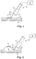
- the apparatus includes an elongated body 30 that has a distal end 32.
- the elongated body 30 may preferably be an endoscope with a suitable number of channels formed therein to accommodate the apparatus of the present invention.
- the apparatus is depicted as positioned proximate a selected site 14 in tissue that includes mucosa 12 and underlying muscularis propria 10.
- the selected site 14 may preferably include a lesion in the form of a tumor, polyp, internal hemorrhoid, etc. tat a practitioner would like to resect.
- the depicted elongated body 30 includes a fluid delivery lumen 24 that extends through at least a portion of the elongated body 30. It maybe preferred that the fluid delivery lumen 24 terminate proximate the distal end 32 of the elongated body 30. It may also be preferred that the fluid delivery lumen 24 extend proximally towards the proximal end (not shown) of the elongated body 30.
- the apparatus depicted in FIG. 1 further includes a needle 20 that is preferably attached to the fluid delivery lumen 24 proximate the distal end 32 of the elongated body 30.
- the needle 20 may preferably be movable between an injection position in which the distal end 22 of the needle 20 extends from the distal end 32 of the elongated body 30 as seen in FIG. 1 . It may also be preferred that the needle 20 be movable to a sheathed position in which the distal end 22 of the needle 20 does not extend past the distal end 32 of the elongated body 30, e.g., is retracted within the elongated body 30.
- FIG. 2 depicts the apparatus of FIG. 1 after insertion of the distal end 22 of the needle 20 into the tissue proximate the selected site 14. It may be preferred that the needle 20 deliver a fluid into the tissue such that the mucosa 12 is separated from the underlying muscularis intestinal 10 by a submucosal fluid cushion 16.
- the fluid used to form the submucosal fluid cushion 16 is preferably delivered through the needle 20, which is preferably in fluid communication with a fluid source 28 through the fluid lumen 24 extending through the elongated body 30.
- the fluid source 28 may take a variety of forms depending on the fluids being supplied.
- the fluid source 28 may be pressurized such that the fluid can be dispensed through a valve (and preferably pressure regulator) without the need for a separate pump.
- a pumping mechanism may be provided in combination with a reservoir that may or may not be pressurized.
- the pressure at which the fluid is delivered may vary, although it may be preferred that the pressure for gases be 20 psig (140 kPa) or more.
- Pressure control may be provided by, e.g., a regulator or other pressure control device.
- the fluid used to form the submucosal fluid cushion 16 may be liquid, gas, or combination thereof. In some instances, it may be preferred that the fluid used to form the submucosal fluid cushion 16 be a liquid, e.g., saline solutions, sodium hyaluronate, glycerol solutions, methylcellulose solutions (such as those described in, e.g., U.S. Patent Application Publication No. 2003/0225460 , titled COMPOSITIONS FOR GENERATING SUBMUCOSAL FLUID CUSHIONS, published December 4, 2003), etc.
- a liquid e.g., saline solutions, sodium hyaluronate, glycerol solutions, methylcellulose solutions (such as those described in, e.g., U.S. Patent Application Publication No. 2003/0225460 , titled COMPOSITIONS FOR GENERATING SUBMUCOSAL FLUID CUSHIONS, published December 4, 2003), etc.
- the fluid used to from the submucosal fluid cushion 16 be a gas, e.g., a gas including gaseous carbon dioxide. In other instances, it may be preferred that the fluid consist essentially of one or more gases, e.g., consist essentially of gaseous carbon dioxide.
- a gaseous fluid to form submucosal fluid cushions may have advantages over submucosal fluid cushions formed using liquid fluids as discussed herein.
- the gases and/or liquids used to form submucosal spaces in blebs may, in some instances, preferably be replaced with solid (i.e., non-flowable) materials to form a resection barrier as discussed herein.
- solid (i.e., non-flowable) materials may be paraffin, biocompatible cyanoacrylate adhesive compositions, etc.
- the resection barrier may be provided by gel or polymer-based structural material (e.g., foam, etc.) that, as delivered, is uncured, but that can be expanded/cured within the submucosal space.
- the resection barrier may preferably be biodegradable and/or bioresorbable such that it could slowly erode over time.
- One potentially suitable expandable material may be a polylactic acid polymer (PLA, e.g., poly-DL-lactide, etc.) which may be provided as a liquid when dissolved in a solvent such as NMP (N-methyl-2-pyrrolidone), but hardens into a pliable structural material when the NMP diffuses out of the polymer mixture.
- PVA polylactic acid polymer
- NMP N-methyl-2-pyrrolidone
- Both NMP and the polymer PLA are generally considered to be inert and bioresorbable for use within the human (or animal) body.
- Other expandable structural materials may be known to those skilled in the art.
- the fluid may be referred to as a barrier precursor.
- formation of the submucosal barrier may involve injecting a barrier precursor into the gas-filled submucosal space, wherein the barrier precursor hardens to form the submucosal barrier.
- barrier precursors described herein may include, e.g., heated paraffin (heated, e.g., to a temperature of 65 degrees Centigrade or higher), cyanoacrylate compositions, uncured biocompatible foams, etc.
- Other barrier precursors may include, e.g., biocompatible photo-curable materials that can be cured upon the application of photo-radiation.
- the apparatus according to the present invention may also preferably include resection devices to resect tissue raised by forming a submucosal fluid cushion.
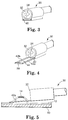
- FIGS. 3-7 depict one exemplary embodiment of such a resection device and its operation.
- the resection device may preferably be provided within a housing located at the distal end 32 of the elongated body 30. As seen in FIG. 3 , the housing may preferably include an opening 26 into which the needle 20 is retracted when in its sheathed position as discussed above with respect to FIGS. 1 & 2 .
- the housing also preferably includes an opening 40 into which a resection frame retracts when in its retracted position.
- a resection frame is depicted in an extended position in which the frame extends from the distal end 32 of the elongated body 30.
- the resection frame may preferably include two spaced apart rails 42a and 42b (referred to collectively as rails 42 herein) and a cross-member 50 connecting the two rails 42 at a location spaced from the distal end 32 of the elongated body 30.
- the rails 42 and the cross-member 50 define a resection opening 44 located between the cross-member 50 and the distal end 32 of the elongated body 30. It may be preferred that the rails 42 and the cross-member 50 of the resection frame define a U-shaped resection opening 44.
- the cross-member 50 include a cutting instrument such that movement of the resection frame to the retracted position (seen in FIG. 3 ) moves the cutting instrument on the cross-member 50 towards the distal end 32 of the elongated body 30. As the resection frame is moved from its extended position seen in FIG. 4 to its retracted position as seen in FIG. 3 , the size of the resection opening 44 decreases.
- selected tissue such as tissue raised above a submucosal fluid cushion
- tissue may be resected by the cutting instrument located on the cross-member 50 as seen in FIG. 6 where the resection frame is nearly completely retracted within the housing at the distal end 32 of the elongated body 30.
- the selected tissue raised by the submucosal fluid cushion include a lesion 14 that is to be removed.
- the cutting instrument on the cross-member 50 may take any suitable form, e.g., blade, wire, etc.
- the cutting action of any cutting instrument may be supplemented by, e.g., electrical energy (e.g., the cutting instrument may be an electrosurgical device).
- resection frames of the present invention be constructed with rails 42 that are rigid members.
- a rigid member is a structure that resists twisting and bending and that also exhibits significant strength in compression along its length as compared to wires or cables used in snare-type resection devices (that exhibit significant strength only in tension and provide only minimal resistance to bending and twisting).
- the rails 42 of resection frames of the present invention be straight and arranged generally parallel to each other.
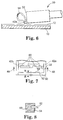
- FIGS. 7 & 8 depict a portion of the resection device to further describe an additional optional feature of the present invention.
- the resection frame including rails 42a and 42b and cross-member 50 are seen FIG. 7 .
- the depicted cross-member 50 includes a blade 52 as a cutting instrument as seen in FIG. 8 .
- the cross-member 50 also preferably includes anvil surfaces 54 adapted to interact with staples 60 retained proximate the distal end 32 of the elongated body.
- the interaction between anvil surfaces 54 and the staples 60 preferably results in stapling of the tissue captured within the resection frame such that after removal of the tissue resected by the blade 52, the edges of the remaining tissue are held together by staples 60.
- the resection and stapling actions may preferably occur substantially at the same time as the resection frame is moved from its extended position towards its retracted position (in the direction of arrows 48 in FIG. 8 ).
- staples 60 are shown as being deformed by anvil surfaces 54, it will be understood that in some devices according to the present invention, the staples may be deformed by other mechanisms, e.g. the staples may be formed of shape memory materials (e.g.. Nitinol, etc.) that deform in the absence of physical force.
- shape memory materials e.g. Nitinol, etc.
- FIGS. 9 & 10 depict another optional feature that may be incorporated into the apparatus of the present invention in the form of a staple cartridge capable of storing multiple sets of staples for delivery to multiple resection sites.
- the cartridge 70 includes staples 60 located in two channels 72 and 74. Although the cartridge 70 includes only two channels, it should be understood that cartridges according to the present invention may include more than two channels of staples.
- the staples 60 may preferably be arranged within each of the channels 72 and 74 such that they are canted at an acute angle with respect to the longitudinal axis 73 of the channel (see FIG. 10 ).
- Each channel may also preferably include a member 76 adapted to bias the staples 60 towards the open end of the channel.
- the member 76 may be biased in the direction of the staples by a resilient member (e.g., spring, elastomeric article, etc.), hydraulic or pneumatic pressure, ratcheting mechanism, etc.).
- the member 76 may be used to advance the staples 60 toward the opening in the channel as staples 60 are dispensed from the cartridge 70.
- FIGS. 11-16 depict another resection device that may be used in connection with the present invention.
- the resection device 100 may preferably be used in connection with an "inside-out" resection procedure as described herein.
- the device 100 includes an outer sheath 102, an inner sheath 104 and an core 106.
- the inner sheath 104 and the outer sheath 102 are movable axially (i.e., along their lengths) with respect to each other with, e.g., the inner sheath 104 moving within a lumen of the outer sheath 102.
- the core 106 is axially movable with respect to the inner sheath 104 within a lumen in the inner sheath 104.
- the device 100 also preferably includes one or more resection wires 108 provided to cut tissue.
- the depicted device includes two resection wires 108, although devices of the invention may include only one resection wire or three or more resection wires.
- the resection wires 108 are attached to the distal end 107 of the core 106.
- the proximal ends of the resection wires 108 are attached to the inner sheath 104, preferably proximate the distal end 105 of the inner sheath 104.
- the proximal ends of the resection wires 108 may be attached to the outer sheath 102 so long as the resection wires 108 do not significantly interfere with advancement of the outer sheath to a selected resection site.
- the resection wires 108 may preferably cut tissue with the use of electrical energy delivered to the wires in accordance with known electrosurgical techniques.
- the device 100 include conductors that extend from the proximal end of the device (not shown) to the distal end (shown).
- the conductors may take the form of wires, electrical traces formed in or on the sheaths, etc.
- the inner sheath 104, core 106 and resection wires 108 be retracted within the outer sheath 102 during advancement of the device 100 to a selected location.
- the outer sheath 102 and inner sheath 104 are preferably manipulated such that the inner sheath 104 extends out of the outer sheath 102 (see, e.g., FIG. 12 ).
- the resection wires 108 are preferably in close proximity to the core 106. As, however, the distal end 105 of the core 104 and the distal end 107 of the core 106 are moved together, the resection wires 108 preferably move radially outward from the core 106 as seen in FIGS. 12 & 13 because their ends are fixedly attached to the inner sheath 104 and the core 106.
- the wires 108 be offset circumferentially about the core 106, as is perhaps best seen in FIGS. 14 & 15 .
- the offset between resection wires 108 maybe measured in degrees and it may be preferred that the resection wires 108 be offset by an angle a (alpha) of about 30 degrees or more, 45 degrees or more, or even 90 degrees or more.
- FIG. 16 depicts the device 100 deployed within the submucosal space of a bleb.
- the device 100 is preferably capable of piercing the tissue forming the bleb such that the core 106 with resection wires 108 can be deployed within the submucosal space.
- the core 106 and inner sheath 104 are preferably manipulated such that the resection wires 108 extend radially outward from the core 106 to contact and cut the separated mucosal tissue.
- electrical energy be provided to the wires 108 to assist in the cutting.
- the resection wires 108 be constructed of a shape memory metal (e.g., nickel titanium alloys, etc.) such that the shape of the resection wires 108 can be further modified based on the temperature of the wires 108. For example, if the wires 108 heat up during an electrosurgical procedure, that temperature increase can be advantageously used to provide additional height to the wires 108 or to cause the wires 108 to take on different selected shapes.
- a shape memory metal e.g., nickel titanium alloys, etc.
- FIGS. 17-23 depict another resection device that may be used in connection with the present invention.
- the resection device 200 may also preferably be used in connection with an "inside-out" resection procedure as described herein.
- the device 200 includes an elongated body 202 having a distal end 203.
- a cutting head 210 is attached to the distal end 203 of the elongated body 202.
- the cutting head 210 preferably includes a cutting member 212 that may preferably be in the form of a fin as seen in FIG. 17 .
- the cutting member 212 preferably includes an edge 214 adapted to cut tissue.
- the cutting member 212 preferably rotates about pin 211 in cutting head 210.
- the cutting member 212 may preferably be adapted for use as an electrosurgical cutting device in which electrical energy is provided to assist the cutting edge 214 in cutting tissue. It may be preferred that conductors be operably connected to the cutting member 212 to provide the electrical energy to the cutting member 212. The conductors preferably extend proximally along elongated body 202 to an electrical power source.
- the cutting head 210 may also preferably include a puncture wire 216 or other piercing structure to assist the device 200 in piercing the tissue forming a bleb.
- the puncture wire 216 may preferably be a relatively thick monofilament polymer or other structure.
- the puncture wire 216 (or other structure) may preferably be retractable within the cutting head 210 to prevent unwanted piercing of tissue as the elongated body 202 is advanced to the selected location.
- FIGS. 20-23 depict use of the device 200 in connection with a bleb.
- the device 200 is advanced such that the puncture wire 216 pierces the tissue of the bleb.
- the cutting member 212 may preferably be in the retracted position within the cutting head 210 as seen in FIG. 20 .
- FIG. 21 depicts the device 200 after insertion into the bleb, with the cutting head 210 fully inserted into the submucosal space formed within the bleb.
- the puncture wire 216 is depicted as retracted back within the cutting head 210, although the puncture wire 216 may not necessarily have to be retracted at this point in the procedure.
- FIG. 22 depicts the device 200 in which the cutting member 212 has been extended from the cutting head 210.
- the cutting member 212 is also depicted as having initiated a cut into the tissue of the bleb.
- FIG. 23 depicts the cutting head 210 in the submucosal space after the elongated body 202 and attached cutting head 210 with cutting member 212 have been withdrawn in the proximal direction (i.e., moving out of the bleb through the opening formed during insertion) such that a portion of the tissue forming the bleb has been cut.
- the cutting head 210 may be repositioned within the submucosal space for another cutting action.
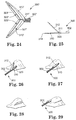
- FIGS. 24-29 depict another resection device that may be used in connection with the present invention.
- the resection device may also preferably be used in connection with an "inside-out" resection procedure as described herein.
- FIG. 24 is a perspective view of one resection device 300' that includes an elongated body 302' with a cutting head at the distal end that includes jaws 310' and 312', both of which may preferably be hinged about an axis 311'.
- the jaw 310' preferably includes a cutting member 320' on the inner surface 321' and the jaw 312' preferably includes a cutting member 322' on its inner surface 323'.
- jaws 310' and 312' include cutting members 320' and 322' in the form of a single blade, it should be understood that the cutting member or members used in connection with the present invention may take any desired form or shape that provides the desired tissue resection.
- the cutting members 320' and 322' may preferably employ electrical energy in an electrosurgical cutting action to assist with tissue resection as is known in the art. If electrical energy is used in the cutting, conductors may preferably be provided to deliver the required electrical energy to the cutting members.
- the electrical conductors may preferably extend along the elongated body from a proximal end (not shown) to the distal end.
- both jaws 310' and 312' are hinged or otherwise capable of rotation with respect to the elongated body 302.
- only one of the jaws may be hinged for rotation.
- FIGS. 25-29 One such embodiment is depicted in FIGS. 25-29 .
- the resection device 300 includes a jaw 310 that preferably does not rotate relative to the distal end 303 of elongated body 302.
- the opposing jaw 312 does, however, preferably rotate about axis 311 such that the jaws 310 and 312 can be moved from an open position (seen in FIG. 25 ) to a closed position (see in FIG. 27 ) in which the jaws are brought together to cut tissue located therebetween.
- jaws 310 and 312 of device 300 have a shape or structure such that the jaw or jaws can pierce tissue, e.g., the tissue forming a bleb.
- jaw 310 preferably includes a tip 314 distal from the elongated body 302 that is preferably adapted to pierce tissue.
- the tissue piercing may be assisted by electrosurgical energy and in other instances, the piercing may be a purely mechanical action.
- FIG. 26 depicts device 300 in use in which the jaw 310 of device 300 is inserted into a bleb using the tissue piercing tip 314.
- the jaw 312 is preferably rotated away from jaw 310 such that the jaws are in the open position. As the device 300 is advanced distally, more of the jaw 310 is inserted into the submucosal space of the bleb.
- FIG. 27 depicts the jaws 310 and 312 of the device 300 in the closed position such that tissue located between the inner surfaces of the jaws 310 and 312 can be cut.
- FIG. 28 depicts the bleb with an incision formed therein after removal of the device 300.
- FIG. 29 depicts the device 300 repositioned relative to the bleb to, e.g., cut the other side of the bleb to assist in removal of the tissue raised within the bleb.
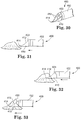
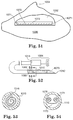
- FIGS. 30-33 depict another resection device that may be used in connection with the present invention.
- the device 400 includes an elongated body 402 and a cap 410 attached to the distal end 403 of the elongated body 402.
- the cap 410 may preferably be in the form of a scoop with two edges that include cutting members 412.
- the cutting members 412 may preferably include proximal ends attached to one side of the distal end 403 of the elongated body 402.
- the cutting members 412 also preferably include distal ends attached to the cap 410, wherein the distal ends converge at the tip 414 of the cap 410.
- the cutting members 412 may preferably employ electrical energy in an electrosurgical cutting action to assist with tissue resection as is known in the art. If electrical energy is used in the cutting, conductors may preferably be provided to deliver the required electrical energy to the cutting members.
- the electrical conductors may preferably extend along the elongated body from a proximal end (not shown) to the distal end 403. It may be preferred that the cutting members 412 located on opposite sides of the cap 410 be electrically isolated from each other such that the cutting action of each cutting member 412 (if electrosurgically enhanced) can be independently controlled.
- FIGS. 31-33 depict the device 400 in use resecting tissue raised within a bleb.
- the general scoop shape of the cap 410 may preferably assist in retaining the tissue in contact with the cutting members 412 attached to the cap 410 in a manner similar to a shovel. It may be preferred that the cap 410 include a relatively sharp tip 414 to assist in initial penetration and piercing of the tissue of the bleb.
- Resection barriers may be used in connection with conventional resection devices and/or at least some of the resection devices of the present invention.
- the resection barrier may be formed by injecting heated paraffin into the submucosal space of a bleb and allowing the paraffin to cool to a point at which it solidifies.
- FIG. 34 depicts one potential apparatus for delivering the heated paraffin to the submucosal space and
- FIG. 35 is a perspective view of one stick 520 of paraffin that may be used with the device of FIG. 34 .
- the paraffin used in connection with the present invention may preferably be sterile medical grade paraffin.
- Medical grade paraffin has a melting point at 65 degrees Celsius and cools/solidifies rapidly when placed in contact with tissue.
- the device 500 is in the general form of a conventional hot glue gun and may preferably include a heating chamber 502 and a plunger 504 adapted to force paraffin out of the heating chamber 502 through an orifice 506. The heated paraffin then preferably passes through a channel 507 to a port 508.
- a delivery device 510 (preferably in the form of, e.g., a needle) is preferably attached to the port 508.
- the delivery device 510 preferably includes a lumen through which the heated paraffin travels to a distal end 512. It may be preferred that the distal end 512 of the delivery device be adapted to pierce tissue such as, e.g., the tissue of a bleb.
- the delivery device 510 include means for providing heat to the lumen such that the temperature of the heated paraffin passing through the lumen is maintained at a level that prevents solidification of the paraffin within the lumen (thus preventing delivery of the heated paraffin to the submucosal space).
- the means for heating may be provided by electrical resistance heaters, fluid chambers adapted to receive heated fluid pumped to the delivery device, RF or microwave heat elements adapted to convert RF or microwave energy to thermal energy, etc.
- the delivery device may preferably include sufficient insulation around the lumen such that the heated paraffin does not solidify during normal use of the device.
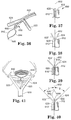
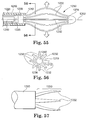
- FIGS. 36-40 depict another apparatus that may be used to remove tissue.
- the tissue to be removed may or may not be raised using a submucosal cushion formed using gas, liquid, or solid material as described herein.
- the apparatus 600 includes a tubular body 610 that includes a distal end 612 and a proximal end (not shown).
- the distal end 612 is preferably advanced to the tissue to be resected while the proximal end preferably remains outside the body of the patient where it can be manipulated.
- the tubular body 610 may preferably be, e.g., an endoscope.
- the tubular body 610 preferably includes a channel in which a spreader sheath 620 is located.
- the spreader sheath 620 preferably includes a lumen in which a resection device 630 is located.
- the lumen extends along the length (longitudinal axis) of the sheath 620 and includes an opening at the distal end of the spreader sheath 620.
- the resection device 630 is axially movable distally and proximally within the lumen in the spreader sheath 620, such that the resection device 620 can be advanced distally out of the opening of the lumen of the spreader sheath 620.
- FIG. 36 A perspective view of the spreader sheath 620 in its deployed configuration with a resection device in the form of a snare 640 advanced through its own sheath 630 is depicted in FIG. 36.
- FIGS. 37-40 depict the apparatus 600 in successive stages of deployment.
- the spreader sheath 620 includes a distal end (shown) and a proximal end (not shown).
- the distal end of the spreader sheath 620 preferably includes spreader arms 622 and 624 movable between a closed position in which the spreader arms are aligned with the longitudinal axis 602 (see FIG. 37 ) and an open position (as depicted in, e.g., FIG.
- each spreader arm 622 and 624 each form an angle ⁇ (beta) with the longitudinal axis 602. It may be preferred that the angle formed by each spreader arm 622 and 624 with the longitudinal axis 602 be at least 15 degrees, in some instances at least 30 degrees, and in other instances at least 45 degrees.
- the spreader arms 622 and 624 may be located in the closed position while within the channel of the tubular member 610 as depicted in, e.g., FIG. 37 . It may be preferred that axial movement of the spreader sheath 620 along the longitudinal axis 602 in the distal direction out of the tubular member 610 allows the spreader arms 622 and 624 to assume the open configuration as depicted in the series of FIGS. 37-40 .
- the spreader arms 622 & 624 have a length of about 1.5 centimeters while the spreader sheath 620 proximal of the spreader arms 622 and 624 have a size of 3.33mm (10 French)
- the spreader arms 622 & 624 may preferably open to an included angle of 90 degrees or more (with each spreader arm moving to a position of 45 degrees off of the longitudinal axis defined for the device).
- the spreader arms 622 and 624 are biased in the open configuration when not constrained within the channel of the tubular member 610.
- the biasing may be performed by a biasing means such as, e.g., elastic members, shape memory materials (e.g., nickel titanium alloys, polymers, etc.), mechanical springs (e.g., leaf, coil, etc.), pistons, etc.
- a biasing means such as, e.g., elastic members, shape memory materials (e.g., nickel titanium alloys, polymers, etc.), mechanical springs (e.g., leaf, coil, etc.), pistons, etc.
- the spreader arms 622 and 624 move back into the closed position when the sheath 620 is withdrawn axially back within the tubular member 610 (in the proximal direction).
- both spreader arms 622 and 624 are depicted as moving equally from the closed to the open position in FIGS. 36-40 , it should be understood that the spreader arms 622 and 624 may not move equally in all embodiments. In some embodiments, for example, only one spreader arm may move from the closed to open position, with the other arm remaining stationary.
- a resection device in the form of a snare 640 that is delivered through its own sheath 630.
- the snare 640 is, in the depicted embodiment, preferably advanced distally through a lumen in the spreader sheath 620 while in its own sheath 630.
- the snare sheath 630 may be advanced out of the spreader sheath 620 as seen in, e.g., FIG. 39 , followed by advancement of the snare 640 in the distal direction out of the snare sheath 630 as seen in, e.g., FIGS. 36 & 40 .
- the snare 640 may preferably include two arms 642 and 644 that are connected at the distal end 646 of the snare 640. If desired, the snare 640 may perform tissue resection with the aid of electrosurgical energy.
- FIGS. 36-40 One potential use for the apparatus of FIGS. 36-40 is in a polypectomy in which the polyp is located, e.g., just above or beyond a haustral fold in the colon.
- a polypectomy in which the polyp is located, e.g., just above or beyond a haustral fold in the colon.
- FIG. 41 One such situation is depicted in FIG. 41 .
- the spreader arms 622 & 624 may be used to push a haustral fold down and keep it in that position, clearing the view to the polyp and allowing the snare 640 to more easily encircle the polyp.
- the apparatus of FIGS. 36-40 could also be used to hold haustral folds down to explore their backsides to determine whether additional polyps might be located there.
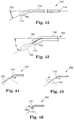
- FIGS. 42-46 depict another resection device that may be used to remove tissue.
- the tissue to be removed may or may not be raised using a submucosal cushion formed using gas, liquid, or solid material as described herein.
- the resection device 700 may include a sheath 710 having both a distal end 712 and a proximal end 714.
- the sheath 710 preferably includes a lumen that opens at the distal end 712.
- the device 700 also preferably includes a snare 720 located within the lumen of the sheath 710.
- the snare 720 is preferably axially movable distally and proximally within the lumen of the sheath 710, such that the snare 720 can be advanced distally out of the opening of the lumen at the distal end 712 of the sheath 710.
- the sheath 710 preferably includes an angled tip proximate the distal end 712 of the sheath 710.
- the angled tip includes a section 716 of the sheath 710 that is oriented off-axis from a longitudinal axis 702 defined by the sheath 710 from the proximal end 714 up to the section that includes the angled tip.
- the section 716 of the sheath 710 that includes the angled tip may preferably include 10% or less of the total length of the sheath 710 from the proximal end 714 to the distal end 712.
- the snare 720 when advanced distally out of the distal end 712 of the sheath 710, exit the sheath 710 at an angle ⁇ (theta) that may preferably be 20 degrees or more off of the longitudinal axis 702 (as depicted in FIG. 43 ).
- ⁇ theta
- the section 716 of the sheath forming the angled tip is depicted as being generally straight along its length, it should be understood that it could be curved or constructed of multiple sections that are straight and/or curved. Regardless, it is preferred that the snare 720 exit the sheath 710 at an angle off of the longitudinal axis 702 as discussed herein.
- Potential advantages of the angled tip may include, e.g., enhanced stiffness in the snare 720 as it exits the sheath 710 as compared to a conventional sheath in which the snare exits the sheath along the longitudinal axis of both components (i.e., the sheath and the snare).
- This additional stiffness in the snare may improve the ability of the snare to encircle polyps or other tissues as depicted in the series of FIGS. 44-46 .
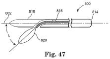
- tissue to be removed may be raised from the surrounding tissue (as in the case, e.g., of a polyp). In some instances, the tissue may or may not be raised using a submucosal cushion formed using gas, liquid, or solid material as described herein.
- the resection device 800 may include a sheath 810 having both a distal end 812 and a proximal end 814.
- the sheath 810 preferably includes a lumen 816 that opens through the side of the sheath 810 at a location proximal from the distal end 812 of the sheath 810.
- the sheath 810 itself, however, preferably extends along the longitudinal axis 802 defined between its distal and proximal ends 812 and 814.
- a distal section of the lumen 816 proximate the distal side opening is oriented off-axis from the longitudinal axis defined between the proximal and distal ends 812 and 814 of the sheath 810. It may be preferred that the side opening in the lumen be located within the distal-most 10% or less of the total length of the sheath 810 (as measured between its proximal and distal ends 812 & 814).
- the device 800 also preferably includes a snare 820 located within the lumen 816 of the sheath 810.
- the snare 820 is preferably axially movable distally and proximally within the lumen 816 such that the snare 820 can be advanced distally out of the opening of the lumen 816 through the opening in the side of the sheath 810.
- the snare 820 exits the sheath 810 through its side, the snare 820 preferably forms an angle ⁇ (lambda) with the longitudinal axis 802 that may preferably be 20 degrees or more off of the longitudinal axis 802.
- Potential advantages of the angled snare 820 may include, e.g., enhanced stiffness in the snare 820 as it exits the sheath 810 as compared to a conventional sheath in which the snare exits the sheath along the longitudinal axis of both components (i.e., the sheath and the snare). This additional stiffness in the snare 820 may improve the ability of the snare to encircle polyps or other tissues.
- FIGS. 48A-48C, 49A-49C, and 50A-50C are depicted in FIGS. 48A-48C, 49A-49C, and 50A-50C .
- the resection device 900 is in the form of a sheath 910 that includes a lumen in which a snare 920 is located.
- the sheath 910 includes both a distal end 912 and a proximal end 914.
- the lumen in the sheath 910 preferably opens at the distal end 912 of the sheath.
- the snare 920 is preferably axially movable distally and proximally within the lumen of the sheath 910, such that the snare 920 can be advanced distally out of the opening of the lumen at the distal end 912 of the sheath 910. It may be preferred that the snare 920 be movable from orientations in which the snare 920 lies substantially within a plane 904 in which the longitudinal axis defined by the distal end 912 and proximal end 914 of the sheath 910 lies as seen in FIG. 48A . Manipulation of the snare as described herein can, however, cause the snare 920 to curve above or below the plane 904. For example, FIG. 48B depicts the snare 920 curving away from the plane 904 in one direction while FIG. 48C depicts the snare 920 curving away from the plane 904 in the opposite direction.
- FIGS. 49A-49C depict the orientation of the wires 922 and 924 within the lumen 916 at a position between the distal end 912 and the proximal end 914 of the sheath 910.
- the wires 922 and 924 are in a neutral orientation within the lumen 916.
- the wire 922 is rotated clockwise about its axis while wire 924 is rotated counterclockwise. The result is depicted in FIG.
- FIG. 48B in which the snare 920 curves upward from the plane 904.
- FIG. 49C the wires 922 and 924 are rotated in the opposite direction, i.e., wire 922 is rotated counterclockwise from the neutral position of FIG. 49A and wire 924 is rotated clockwise.
- the result is depicted in FIG. 48C in which the snare 920 curves downward with respect to the plane 904.
- FIGS. 50A-50C depict one apparatus that may be used to rotate the wires 922 and 924 as discussed herein to control the orientation of the snare 920.
- the apparatus includes a plunger 930 that may preferably be located proximate the proximal end 914 of the sheath 910.
- the depicted plunger 930 traverses the lumen 916 of the sheath 910 and is located between the wires 922 and 924.
- the plunger 930 may preferably include ribs 932 that cooperate with the wires 922 and 924 such that movement of the plunger 930 transverse to the longitudinal axis 902 (out of the page in FIGS. 50A-50C ) rotates the wires 922 and 924 about their respective longitudinal axes.
- FIGS. 50A-50C depict one mechanism for rotating the wires 922 and 924, many other mechanisms that accomplish the same function may be used in place of that depicted in FIGS. 50A-50C .
- FIGS. 51-54 depict another exemplary apparatus of the present invention in which a barrier sheet is deployed within the submucosal space of a bleb.
- FIG. 51 in particular depicts (in partial cross-sectional view) a barrier sheet 1070 located within the submucosal space 1002 that may preferably be located beneath, e.g., a polyp 1004 or other tissue to be resected.
- the barrier sheet 1070 may preferably include a central area 1072 and a raised lip 1071 that may preferably extend about a periphery of the central area 1072.
- the lip 1071 may be integrally formed with the material of the central area 1072 or it may be attached thereto. Furthermore, the lip 1071 may extend continuously about the perimeter of the central area 1072 or it may be discontinuous.
- the barrier sheet 1070 is provided to act as a barrier to protect the underlying submucosal tissue during resection procedures. It may be preferred that conventional cutting instruments such as blades, etc. that may be used to remove tissue cannot readily perforate or cut the barrier sheet 1070. As a result, the barrier sheet 1070 may preferably significantly reduce the risk of perforating an underlying tissue wall. Other potential functions of the barrier sheet 1070 may include, e.g., reducing diffusion of any gas, liquid, foam, etc.
- the tissue underlying the barrier sheet providing a tactile response to the practitioner during resection (thus providing, e.g., an indication of the location of the bottom of the submucosal space or the edges of the space - using, e.g., the optional lip 1071), etc.
- the barrier sheets of the present invention be manufactured of one or more materials that exhibit shape memory properties.
- the lip 1071 of the barrier sheet 1070 be manufactured of shape memory materials while the central area 1072 may be manufactured of materials that may or may not exhibit shape memory properties.
- the central area 1072 may be manufactured of shape memory materials while the lip 1071 is manufactured of materials that may or not exhibit shape memory properties.
- Barrier sheets manufactured of two or more different materials may be manufactured by a variety of techniques, e.g., coextrusion, coinjection molding, insert molding, etc.
- Delivery of the barrier sheet 1070 into the submucosal space 1002 may be accomplished by any suitable technique.
- One exemplary apparatus and technique may be described in connection with FIGS. 52-54 .
- Delivery may, therefore be accomplished by pushing or ejecting the barrier sheet 1070 and allowing it to uncoil within the submucosal space 1002.
- the coiled barrier sheet 1070 may preferably be located proximate a distal end 1012 of a delivery sheath 1010 as depicted in, e.g., FIG. 52 .
- the barrier sheet 1070 is preferably located within a lumen 1020 of the delivery sheath 1010 when inserting the barrier sheet 1070 into the submucosal space 1002.
- it maybe moved out of the lumen 1020 of the sheath 1010 through an opening at the distal end of the delivery sheath 1010. Because the barrier sheet 1070 is restrained in its coiled configuration while in the lumen 1020, ejecting the barrier sheet 1070 from the lumen 1020 results in uncoiling the barrier sheet 1070 within the submucosal space 1002.
- one exemplary method depicted in FIG. 52 includes an ejection device 1080 that may preferably advance toward the distal end 1012, forcing the barrier sheet 1070 out of the lumen 1020 using surface 1082 as it advances distally (i.e., in the distal direction of the sheath 1010).
- the ejection device 1080 may preferably be operably connected to an actuator 1084 that may preferably be located proximate the proximal end 1014 of the delivery sheath 1010.
- the distal end 1012 of the sheath 1010 may preferably be adapted to pierce or perforate tissue, such as the tissue of a bleb, such that the opening of the lumen 1020 is located within the submucosal space where the barrier sheet 1070 can be deployed.
- tissue such as the tissue of a bleb
- the sheath 1010 may be inserted into the submucosal space through a variety of other techniques and/or apparatus.
- FIG. 52 depicted sheath, ejection device, actuator, etc. depicted in FIG. 52 are exemplary in nature only and that any suitable apparatus or mechanism that can deliver and deploy the barrier sheets of the present invention may be used.
- FIG. 53 is a cross-sectional view of barrier sheet 1070 and sheath 1010 taken along line 53-53 in FIG. 52 .
- the barrier sheet 1070 includes only one coil when located within lumen 1020.
- the barrier sheets of the present invention may be stored within the lumen of delivery sheath in a variety of other configurations.
- One such alternative is depicted in the cross-sectional vie of FIG. 54 in which barrier sheet 1170 includes two coils 1174 & 1176 when located within lumen 1120 of sheath 1110.
- the coils 1174 & 1176 may preferably be rolled inwardly towards each other in opposing directions as depicted.
- a potential advantage of a two-coil configuration is that uncoiling of the barrier sheet 1170 within a submucosal space may be facilitated with two smaller coils such as are depicted in FIG. 54 .
- the barrier sheets of the present invention may be manufactured of a variety of different materials, although the materials may preferably possess the functional characteristics discussed herein (such as, e.g., flexibility and memory sufficient to allow for coiling and uncoiling).
- the barrier sheets may preferably be constructed of biosorbable materials.
- Some exemplary materials may include, e.g., films, woven fabrics, non-woven fabrics, laminates of films and/or fabrics, etc.
- the materials may include, e.g., GORE-TEX fabrics, polypropylene, polyurethane, etc. It may be preferred that the materials used to construct the barrier sheets resist electro-cautery currents (e.g., possess low electrical conductivity). Examples of some suitable materials maybe described in, e.g., U.S.
- the thickness of the materials used for barrier sheets of the present invention may preferably be, e.g., 1 millimeter or less (although in some instances, the thickness may be greater, e.g., for use in laparoscopic procedures).
- the overall size of the barrier sheets may also be dependent on the needs of a selected procedure, e.g., in some instances, the barrier sheets may be 10 centimeters or more across and in other procedures, the barrier sheets may be 1 centimeter or less across.
- FIGS. 55 & 56 Still another apparatus that may be used to assist in tissue resection is depicted in FIGS. 55 & 56 .
- the depicted apparatus may be used to prop open a variety of internal body locations, such as, e.g., body lumens (colon, gastro-intestinal, blood vessels, urinary tract, etc.).
- body lumens colon, gastro-intestinal, blood vessels, urinary tract, etc.
- the apparatus of FIGS. 55 & 56 may be used to maintain the submucosal space in the absence of, e.g., the gas, liquid, or other material used to create the submucosal space.
- the depicted device includes a delivery sheath 1210 and a cage 1230.
- the delivery sheath 1210 includes a lumen with an opening at a distal end of the delivery sheath 1210.
- the delivery sheath 1210 defines a longitudinal axis extending between its distal end and a proximal end.
- the cage 1230 is operatively connected to an actuator that extends through the lumen to the proximal end of the delivery sheath 1210.
- the actuator is preferably movable to advance the cage 1230 out of the lumen and retract the cage 1230 within the lumen.
- the cage 1230 can be advanced out of the lumen 1220 of the sheath 1210 such that the cage 1230 expands to, e.g., support tissue.
- the cage 1230 includes struts 1232 that extend between a distal retainer 1234 and a proximal retainer 1236.
- the proximal retainer 1236 may preferably be operated from a proximal end of the apparatus such that the sheath 1210 and the cage 1230 can be moved relative to each other in the proximal and distal directions. Movement such that the cage 1230 extends out of the lumen 1220 of the sheath 1210 maybe accomplished using an actuator 1228 (the distal end of which is depicted in FIG. 55 ).
- the struts 1232 of the cage 1230 may preferably be in a restrained configuration when located within the lumen 1220 and an expanded configuration when advanced distally out of the lumen 1220.
- the struts 1232 In the expanded configuration as depicted in FIG. 55 , the struts 1232 preferably move radially outward from the longitudinal axis 1202 that extends along the length of the sheath 1210.
- the struts 1232 when deployed outside of the lumen 1220 may not fully expand if they are in an internal body location that constrains their expansion.
- the force applied by the struts 1232 on the surrounding tissue may, however, preferably force the tissue outward from the longitudinal axis 1202.
- struts 1232 are depicted as expanding generally equally in all directions, it will be understood that they may preferentially expand on only one or more directions.
- the struts 1232 are depicted as taking a generally bell-shape when expanded, it will be understood that they may take a variety of different shapes.
- the expansion force used to expand the cage 1230 may preferably be supplied by the struts 1232 themselves which may preferably be constructed of materials that can be restrained within the lumen 1220 of sheath 1210 for delivery, but can then expand when released from the constraints of the lumen 1220. It may further be preferred that the struts 1232 possess physical characteristics such as elasticity and resiliency that allow the cage 1230 to be retracted back into lumen 1220 after advancement out of the lumen 1220.
- Retraction and advancement may preferably be used to control the size of the cage 1230 within, e.g., the submucosal space of a bleb or any other selected location (e.g., internal body lumens in the colon, gastro-intestinal system, blood vessels, urinary tract, etc.).
- Suitable materials for the struts 1232 of the cage 1230 may include, e.g., metals, polymers, shape memory metals, shape memory polymers, etc.
- the distal and proximal retainers 1234 and 1236 may be made of the same or different materials.
- the cage 1230 may be designed to allow the passage of an apparatus 1240 into the volume of the expanded cage 1230.
- the apparatus 1240 maybe, e.g. an imaging device (e.g., colonoscope, etc.), resection device (for resecting tissue surrounding or extending into the cage 1230), etc.
- the apparatus 1240 may preferably be movable longitudinally within the delivery sheath 1210, wherein the device 1240 can be advanced into the cage 1230 when the cage 1230 is in the expanded configuration. It may also be preferred that the apparatus 1240 be capable of retraction in the proximal direction such that the apparatus 1240 can be withdrawn back into the delivery sheath 1210.
- delivery sheath 1210 Although only one lumen is depicted in delivery sheath 1210, it should be understood that multiple lumens could be provided to allow for independent advancement and retraction of the cage 1230 and apparatus 1240. Further, although only one apparatus 1240 is depicted, it should be understood that more than one apparatus could be advanced into the cage 1230 at one time.
- FIG. 57 Still another variation of the apparatus is depicted in FIG. 57 in which a cage 1330 is provided without a distal retainer such that as the sheath 1310 is withdrawn, the struts 1332 of the cage 1330 expand in the absence of distal retainer. Although a distal retainer such as that seen in FIG. 55 is not included, the distal ends of the struts 1332 may still be connected to each other if so desired. Advancement of the sheath 1310 in the distal direction may preferably cause the cage 1320 to collapse such that the struts 1332 are again contained within the sheath 1310 (as described above in connection with, e.g., the embodiment of FIGS. 55 & 56 ).
- the apparatus of the present invention may use a variety of different actuating mechanisms to move the needles, resection frames, staples, jaws, cutting members, snares, etc.
- the actuators may be in the form of electromagnetic actuators, hydraulic actuators, pneumatic actuators, screw drives, push/pull rods extending the length of the elongated body for manual operation by a user, etc.
- the specific actuating mechanism(s) selected will be known to those of skill in the art of medical devices.
- the resection devices of the invention may preferably be mounted on elongated bodies for delivery to internal body locations, potentially through or on an endoscope.
- the materials used to construct the various resection devices may preferably be those materials suitable for use in medical devices, e.g., metals, polymers, composite materials, etc.
Claims (8)
- Appareil de résection endoscopique comprenant :un corps allongé (30) comprenant une extrémité proximale et une extrémité distale (32) ;une structure de résection disposée à proximité de l'extrémité distale du corps allongé, la structure de résection comprenant deux rails espacés l'un de l'autre (42a, 42b) et un élément transversal (50) reliant les deux rails à un endroit espacé de l'extrémité distale (32) du corps allongé (30), la structure de résection comprenant une position déployée et une position rétractée ;un instrument de coupe (52) disposé sur l'élément transversal (50) entre les deux rails espacés l'un de l'autre (42a, 42b) de la structure de résection, l'instrument de coupe étant soumis à un déplacement à partir de l'extrémité distale (32) du corps allongé (30) lorsque la structure de résection se trouve dans la position déployée, et dans lequel un mouvement de la structure de résection en direction de la position rétractée déplace l'élément transversal (50) et l'instrument de coupe (52) dans la direction de l'extrémité distale du corps allongé ;une ouverture de résection (44) définie par les deux rails espacés l'un de l'autre (42a, 42b), par l'élément transversal (50) et par l'extrémité distale (32) lorsque la structure de résection se trouve dans la position déployée, appareil dans lequel la dimension de l'ouverture de résection diminue, et dans lequel du tissu qui s'étend à travers l'ouverture de résection est découpé par l'instrument de coupe lorsque la structure de résection se déplace pour prendre la position rétractée à partir de la position déployée, ledit appareil de résection endoscopique étant caractérisé en ce qu'il comprend en outre :un certain nombre d'agrafes (60), maintenues à proximité de l'extrémité distale (32) du corps allongé (30) et une enclume d'agrafage (54) disposée sur l'élément transversal (50), et dans lequel ladite multitude d'agrafes et l'enclume d'agrafage sont d'isposés sur les côtés opposés de l'ouverture de résection lorsque la structure de résection se trouve dans la position déployée, et dans lequel en outre le mouvement de la structure de résection pour prendre la position rétractée force ladite multitude d'agrafes en contact avec l'enclume d'agrafage, les agrafes et l'enclume d'agrafage coopérant pour agrafer le tissu qui s'étend à travers l'ouverture de résection lorsque la structure de résection se déplace pour prendre la position rétractée à partir de la position déployée.
- Appareil selon la revendication 1, dans lequel l'instrument de coupe (52) comprend une lame.
- Appareil selon l'une quelconque des revendications 1 ou 2, dans lequel les deux rails espacés l'un de l'autre (42a, 42b) comprennent des éléments rigides.
- Appareil selon l'une quelconque des revendications 1 à 3, dans lequel les deux rails espacés l'un de l'autre (42a, 42b) et l'élément transversal (50) définissent une ouverture de résection (44) possédant une configuration en forme de U.
- Appareil selon l'une quelconque des revendications 1 à 4, comprenant en outre une lumière de distribution de fluide (24) qui s'étend à travers au moins une portion du corps allongé (30), la lumière de distribution de fluide se terminant à proximité de l'extrémité distale (32) du corps allongé, l'appareil comprenant en outre une aiguille (20) fixée à la lumière de distribution de fluide à proximité de l'extrémité distale du corps allongé, l'aiguille étant mobile entre une position d'injection dans laquelle l'aiguille s'étend à partir de l'extrémité distale du corps allongé et une position à l'état enveloppé d'une gaine dans laquelle l'aiguille est disposée au sein du corps allongé.
- Appareil selon la revendication 5, comprenant en outre une source de fluide (28) reliée à la lumière de distribution de fluide (24), la source de fluide comprenant un fluide conçu pour former des coussinets fluides sous-muqueux dans le tissu muqueux.
- Appareil selon la revendication 6, dans lequel le fluide comprend un liquide.
- Appareil selon la revendication 6, dans lequel le fluide comprend un gaz.
Applications Claiming Priority (2)
| Application Number | Priority Date | Filing Date | Title |
|---|---|---|---|
| US67976005P | 2005-05-11 | 2005-05-11 | |
| PCT/US2006/018322 WO2006122279A2 (fr) | 2005-05-11 | 2006-05-11 | Dispositif et procedes pour interventions chirurgicales internes |
Publications (3)
| Publication Number | Publication Date |
|---|---|
| EP1885259A2 EP1885259A2 (fr) | 2008-02-13 |
| EP1885259A4 EP1885259A4 (fr) | 2014-02-19 |
| EP1885259B1 true EP1885259B1 (fr) | 2016-08-17 |
Family
ID=37397319
Family Applications (1)
| Application Number | Title | Priority Date | Filing Date |
|---|---|---|---|
| EP06759611.4A Active EP1885259B1 (fr) | 2005-05-11 | 2006-05-11 | Dispositif pour interventions chirurgicales internes |
Country Status (5)
| Country | Link |
|---|---|
| US (3) | US8287535B2 (fr) |
| EP (1) | EP1885259B1 (fr) |
| JP (1) | JP5144504B2 (fr) |
| ES (1) | ES2599854T3 (fr) |
| WO (1) | WO2006122279A2 (fr) |
Families Citing this family (203)
| Publication number | Priority date | Publication date | Assignee | Title |
|---|---|---|---|---|
| US8714429B2 (en) | 2003-04-29 | 2014-05-06 | Covidien Lp | Dissecting tip for surgical stapler |
| US20070084897A1 (en) | 2003-05-20 | 2007-04-19 | Shelton Frederick E Iv | Articulating surgical stapling instrument incorporating a two-piece e-beam firing mechanism |
| US9060770B2 (en) | 2003-05-20 | 2015-06-23 | Ethicon Endo-Surgery, Inc. | Robotically-driven surgical instrument with E-beam driver |
| EP1680028B1 (fr) | 2003-10-17 | 2012-01-25 | Tyco Healthcare Group LP | Dispositif d'agrafage chirurgical |
| US11890012B2 (en) | 2004-07-28 | 2024-02-06 | Cilag Gmbh International | Staple cartridge comprising cartridge body and attached support |
| EP1885259B1 (fr) | 2005-05-11 | 2016-08-17 | Mayo Foundation For Medical Education And Research | Dispositif pour interventions chirurgicales internes |
| US20070060887A1 (en) * | 2005-08-22 | 2007-03-15 | Marsh David A | Ophthalmic injector |
| US7789881B2 (en) | 2005-08-25 | 2010-09-07 | Boston Scientific Scimed, Inc. | Endoscopic resection method |
| US10159482B2 (en) | 2005-08-31 | 2018-12-25 | Ethicon Llc | Fastener cartridge assembly comprising a fixed anvil and different staple heights |
| US7669746B2 (en) | 2005-08-31 | 2010-03-02 | Ethicon Endo-Surgery, Inc. | Staple cartridges for forming staples having differing formed staple heights |
| US11246590B2 (en) | 2005-08-31 | 2022-02-15 | Cilag Gmbh International | Staple cartridge including staple drivers having different unfired heights |
| US8186555B2 (en) | 2006-01-31 | 2012-05-29 | Ethicon Endo-Surgery, Inc. | Motor-driven surgical cutting and fastening instrument with mechanical closure system |
| US8708213B2 (en) | 2006-01-31 | 2014-04-29 | Ethicon Endo-Surgery, Inc. | Surgical instrument having a feedback system |
| US7845537B2 (en) | 2006-01-31 | 2010-12-07 | Ethicon Endo-Surgery, Inc. | Surgical instrument having recording capabilities |
| US11793518B2 (en) | 2006-01-31 | 2023-10-24 | Cilag Gmbh International | Powered surgical instruments with firing system lockout arrangements |
| US8211114B2 (en) * | 2006-04-24 | 2012-07-03 | Ethicon Endo-Surgery, Inc. | Medical instrument having a medical snare |
| US9138250B2 (en) | 2006-04-24 | 2015-09-22 | Ethicon Endo-Surgery, Inc. | Medical instrument handle and medical instrument having a handle |
| US7837620B2 (en) | 2006-04-25 | 2010-11-23 | Ethicon Endo-Surgery, Inc. | Medical tubular assembly |
| US7927327B2 (en) | 2006-04-25 | 2011-04-19 | Ethicon Endo-Surgery, Inc. | Medical instrument having an articulatable end effector |
| US7758593B2 (en) * | 2006-05-04 | 2010-07-20 | Ethicon Endo-Surgery, Inc. | Medical instrument handle and medical instrument having same |
| US7597661B2 (en) | 2006-05-11 | 2009-10-06 | Ethicon Endo-Surgery, Inc. | Medical instrument having a catheter and method for using a catheter |
| US7959642B2 (en) | 2006-05-16 | 2011-06-14 | Ethicon Endo-Surgery, Inc. | Medical instrument having a needle knife |
| US7887521B2 (en) * | 2006-05-17 | 2011-02-15 | Alcon Research, Ltd. | Ophthalmic injection system |
| US7811252B2 (en) * | 2006-05-17 | 2010-10-12 | Alcon Research, Ltd. | Dosage control device |
| US20070270744A1 (en) * | 2006-05-17 | 2007-11-22 | Bruno Dacquay | Limited Reuse Assembly For Ophthalmic Injection Device |
| US8136711B2 (en) | 2006-09-08 | 2012-03-20 | Tyco Healthcare Group Lp | Dissection tip and introducer for surgical instrument |
| US8403196B2 (en) | 2006-09-08 | 2013-03-26 | Covidien Lp | Dissection tip and introducer for surgical instrument |
| CN102014987A (zh) * | 2006-10-16 | 2011-04-13 | 爱尔康研究有限公司 | 操作带有一次性端部的眼科手持机的方法 |
| US20080281292A1 (en) * | 2006-10-16 | 2008-11-13 | Hickingbotham Dyson W | Retractable Injection Port |
| US9022970B2 (en) * | 2006-10-16 | 2015-05-05 | Alcon Research, Ltd. | Ophthalmic injection device including dosage control device |
| EP2063829B1 (fr) * | 2006-10-16 | 2010-12-08 | Alcon Research, Ltd. | Ensemble universel rechargeable réutilisable un nombre limité de fois destiné à une pièce à main ophtalmique |
| US8221443B2 (en) | 2006-11-15 | 2012-07-17 | Mayo Foundation For Medical Education And Research | Submucosal endoscopy with mucosal flap methods and kits |
| ATE529056T1 (de) * | 2006-12-14 | 2011-11-15 | Ethicon Endo Surgery Inc | Gewebeklammer zur endoluminalen, lokalen gewebeexzision |
| US8684253B2 (en) | 2007-01-10 | 2014-04-01 | Ethicon Endo-Surgery, Inc. | Surgical instrument with wireless communication between a control unit of a robotic system and remote sensor |
| US8540128B2 (en) | 2007-01-11 | 2013-09-24 | Ethicon Endo-Surgery, Inc. | Surgical stapling device with a curved end effector |
| US9636015B2 (en) * | 2007-04-17 | 2017-05-02 | Covidien Lp | Colon polyp staging methods |
| US8931682B2 (en) | 2007-06-04 | 2015-01-13 | Ethicon Endo-Surgery, Inc. | Robotically-controlled shaft based rotary drive systems for surgical instruments |
| US11857181B2 (en) | 2007-06-04 | 2024-01-02 | Cilag Gmbh International | Robotically-controlled shaft based rotary drive systems for surgical instruments |
| KR101119357B1 (ko) * | 2007-06-21 | 2012-03-06 | 플루오르 테크놀로지스 코포레이션 | 황 회수 유닛용 공기 수요량 피드백 제어 시스템 |
| US11849941B2 (en) | 2007-06-29 | 2023-12-26 | Cilag Gmbh International | Staple cartridge having staple cavities extending at a transverse angle relative to a longitudinal cartridge axis |
| BRPI0901282A2 (pt) | 2008-02-14 | 2009-11-17 | Ethicon Endo Surgery Inc | instrumento cirúrgico de corte e fixação dotado de eletrodos de rf |
| WO2009114779A2 (fr) * | 2008-03-14 | 2009-09-17 | Safestitch Medical, Inc. | Agrafeuse pour hernie avec manipulateur de filet intégré |
| US8870049B2 (en) | 2008-03-14 | 2014-10-28 | Transenterix, Inc. | Hernia stapler |
| JP5288101B2 (ja) * | 2008-03-27 | 2013-09-11 | 国立大学法人鳥取大学 | 内視鏡用注射具および内視鏡的切除術用の手術キット |
| EP2633823B1 (fr) * | 2008-04-21 | 2016-06-01 | Covidien LP | Dispositifs emboliques à balle tressée et systèmes de mise en place |
| US9675482B2 (en) | 2008-05-13 | 2017-06-13 | Covidien Lp | Braid implant delivery systems |
| CA2731735A1 (fr) * | 2008-07-22 | 2010-01-28 | Microtherapeutics, Inc. | Dispositif de remodelage vasculaire |
| US9005230B2 (en) | 2008-09-23 | 2015-04-14 | Ethicon Endo-Surgery, Inc. | Motorized surgical instrument |
| US9386983B2 (en) | 2008-09-23 | 2016-07-12 | Ethicon Endo-Surgery, Llc | Robotically-controlled motorized surgical instrument |
| JP5431705B2 (ja) * | 2008-09-29 | 2014-03-05 | オリンパス株式会社 | 線維層切除器具 |
| US8608045B2 (en) | 2008-10-10 | 2013-12-17 | Ethicon Endo-Sugery, Inc. | Powered surgical cutting and stapling apparatus with manually retractable firing system |
| WO2010081029A1 (fr) | 2009-01-08 | 2010-07-15 | Rotation Medical, Inc. | Systèmes implantables de protection des tendons et trousses et procédés associés |
| US9179910B2 (en) * | 2009-03-20 | 2015-11-10 | Rotation Medical, Inc. | Medical device delivery system and method |
| EP3308743A1 (fr) | 2009-06-04 | 2018-04-18 | Rotation Medical, Inc. | Procédés et appareil de déploiement de matériaux de type feuille |
| CA2763919C (fr) | 2009-06-04 | 2017-05-23 | Rotation Medical, Inc. | Appareil de reparation de materiaux de type feuille en vue d'un tissu cible |
| US20110202085A1 (en) | 2009-11-09 | 2011-08-18 | Siddharth Loganathan | Braid Ball Embolic Device Features |
| US8652146B2 (en) * | 2010-01-27 | 2014-02-18 | Merit Medical Systems, Inc. | Shapeable retrieval device and method of using |
| EP2528541B1 (fr) * | 2010-01-28 | 2016-05-18 | Covidien LP | Dispositif de remodelage vasculaire |
| US9468442B2 (en) * | 2010-01-28 | 2016-10-18 | Covidien Lp | Vascular remodeling device |
| US9198750B2 (en) | 2010-03-11 | 2015-12-01 | Rotation Medical, Inc. | Tendon repair implant and method of arthroscopic implantation |
| US11812965B2 (en) | 2010-09-30 | 2023-11-14 | Cilag Gmbh International | Layer of material for a surgical end effector |
| US9282962B2 (en) | 2010-09-30 | 2016-03-15 | Ethicon Endo-Surgery, Llc | Adhesive film laminate |
| US11849952B2 (en) | 2010-09-30 | 2023-12-26 | Cilag Gmbh International | Staple cartridge comprising staples positioned within a compressible portion thereof |
| US10945731B2 (en) | 2010-09-30 | 2021-03-16 | Ethicon Llc | Tissue thickness compensator comprising controlled release and expansion |
| US9386988B2 (en) | 2010-09-30 | 2016-07-12 | Ethicon End-Surgery, LLC | Retainer assembly including a tissue thickness compensator |
| US9629814B2 (en) | 2010-09-30 | 2017-04-25 | Ethicon Endo-Surgery, Llc | Tissue thickness compensator configured to redistribute compressive forces |
| WO2012078678A1 (fr) | 2010-12-06 | 2012-06-14 | Tyco Healthcare Group Lp | Dispositif de remodelage vasculaire |
| WO2012094405A1 (fr) | 2011-01-04 | 2012-07-12 | Merit Medical Systems, Inc. | Piège à boucles multiples |
| CN103442653B (zh) | 2011-02-11 | 2016-06-01 | 柯惠有限合伙公司 | 两阶段展开动脉瘤栓塞装置 |
| US9314314B2 (en) | 2011-02-15 | 2016-04-19 | Rotation Medical, Inc. | Anatomical location markers and methods of use in positioning sheet-like materials during surgery |
| WO2012145059A1 (fr) | 2011-02-15 | 2012-10-26 | Rotation Medical, Inc. | Procédés et appareil pour fixer des matériaux de type en feuille à un tissu cible |
| WO2012112565A2 (fr) | 2011-02-15 | 2012-08-23 | Rotation Medical, Inc. | Procédés et appareil pour la distribution et le positionnement de matériaux en feuille |
| WO2012134990A1 (fr) | 2011-03-25 | 2012-10-04 | Tyco Healthcare Group Lp | Dispositif de remodelage vasculaire |
| US8974479B2 (en) | 2011-03-30 | 2015-03-10 | Covidien Lp | Ultrasonic surgical instruments |
| CA2834649C (fr) | 2011-04-29 | 2021-02-16 | Ethicon Endo-Surgery, Inc. | Cartouche d'agrafes comprenant des agrafes positionnees a l'interieur d'une partie compressible de celle-ci |
| US9039713B2 (en) | 2011-05-13 | 2015-05-26 | Merit Medical Systems, Inc. | Releasably attached snare loop retrieval device and method of using the same |
| WO2013028381A1 (fr) | 2011-08-19 | 2013-02-28 | Cook Medical Technologies Llc | Capuchon destiné à être fixé à un endoscope |
| CA2845528C (fr) * | 2011-08-19 | 2016-09-27 | Cook Medical Technologies Llc | Capuchon d'ablation |
| WO2013049448A1 (fr) | 2011-09-29 | 2013-04-04 | Covidien Lp | Dispositif de remodelage vasculaire |
| US8882680B2 (en) | 2011-12-02 | 2014-11-11 | Interscope, Inc. | Insertable endoscopic instrument for tissue removal |
| US9033895B2 (en) | 2011-12-02 | 2015-05-19 | Interscope, Inc. | Endoscope including an torque generation component or torque delivery component disposed within an insertable portion of the endoscope and a surgical cutting assembly insertable within the endoscope |
| US11076840B2 (en) | 2011-12-02 | 2021-08-03 | Interscope, Inc. | Surgical console, specimen receiver, and insertable endoscopic instrument for tissue removal |
| US9808146B2 (en) | 2011-12-02 | 2017-11-07 | Interscope, Inc. | Endoscopic tool for debriding and removing polyps |
| US9204868B2 (en) | 2011-12-02 | 2015-12-08 | Interscope, Inc. | Methods and apparatus for removing material from within a mammalian cavity using an insertable endoscopic instrument |
| US9033864B2 (en) | 2011-12-02 | 2015-05-19 | Interscope, Inc. | Endoscope including a torque generation component or torque delivery component disposed within an insertable portion of the endoscope and a surgical cutting assembly insertable within the endoscope |
| US9028424B2 (en) | 2011-12-02 | 2015-05-12 | Interscope, Inc. | Endoscope including a torque generation component or torque delivery component disposed within an insertable portion of the endoscope and a surgical cutting assembly insertable within the endoscope |
| US9107661B2 (en) | 2011-12-19 | 2015-08-18 | Rotation Medical, Inc. | Fasteners and fastener delivery devices for affixing sheet-like materials to bone or tissue |
| WO2013096224A1 (fr) | 2011-12-19 | 2013-06-27 | Rotation Medical, Inc. | Organes de fixation pour fixer des matériaux en feuille à un os ou à un tissu |
| WO2013119321A1 (fr) | 2011-12-19 | 2013-08-15 | Rotation Medical, Inc. | Organes de fixation et dispositifs de distribution d'organes de fixation pour fixer des matières de type feuille à un os ou à un tissu |
| CA2859543A1 (fr) | 2011-12-19 | 2013-06-27 | Rotation Medical, Inc. | Appareil et procede de formation de trous de guidage dans l'os et delivrant des fixations dans un implant |
| USD855802S1 (en) | 2011-12-23 | 2019-08-06 | Interscope, Inc. | Disposable tool |
| WO2013101640A1 (fr) | 2011-12-29 | 2013-07-04 | Rotation Medical, Inc. | Fil-guide ayant un élément de fixation distal pour la pose et le positionnement de matières de type feuille en chirurgie |
| WO2013101638A1 (fr) | 2011-12-29 | 2013-07-04 | Rotation Medical, Inc. | Procédés et appareil de distribution et de positionnement de matières de type feuille en chirurgie |
| BR112014024098B1 (pt) | 2012-03-28 | 2021-05-25 | Ethicon Endo-Surgery, Inc. | cartucho de grampos |
| BR112014024102B1 (pt) | 2012-03-28 | 2022-03-03 | Ethicon Endo-Surgery, Inc | Conjunto de cartucho de prendedores para um instrumento cirúrgico, e conjunto de atuador de extremidade para um instrumento cirúrgico |
| US9186173B2 (en) * | 2012-04-27 | 2015-11-17 | Specialty Care, Inc. | Optical obturator system |
| US20140001231A1 (en) | 2012-06-28 | 2014-01-02 | Ethicon Endo-Surgery, Inc. | Firing system lockout arrangements for surgical instruments |
| US9289256B2 (en) | 2012-06-28 | 2016-03-22 | Ethicon Endo-Surgery, Llc | Surgical end effectors having angled tissue-contacting surfaces |
| US9526570B2 (en) | 2012-10-04 | 2016-12-27 | Cook Medical Technologies Llc | Tissue cutting cap |
| US9186267B2 (en) | 2012-10-31 | 2015-11-17 | Covidien Lp | Wing bifurcation reconstruction device |
| US9314248B2 (en) | 2012-11-06 | 2016-04-19 | Covidien Lp | Multi-pivot thrombectomy device |
| US9295571B2 (en) | 2013-01-17 | 2016-03-29 | Covidien Lp | Methods and apparatus for luminal stenting |
| US9936951B2 (en) | 2013-03-12 | 2018-04-10 | Covidien Lp | Interchangeable tip reload |
| US20140276774A1 (en) * | 2013-03-14 | 2014-09-18 | Boston Scientific Scimed, Inc. | Tissue dissection device and related methods of use |
| US9463105B2 (en) | 2013-03-14 | 2016-10-11 | Covidien Lp | Methods and apparatus for luminal stenting |
| US9452011B2 (en) | 2013-03-15 | 2016-09-27 | Gyrus Acmi, Inc. | Combination electrosurgical device |
| CN105163683B (zh) | 2013-03-15 | 2018-06-15 | 捷锐士阿希迈公司(以奥林巴斯美国外科技术名义) | 电外科器械 |
| CN105380711B (zh) | 2013-03-15 | 2018-01-02 | 捷锐士阿希迈公司(以奥林巴斯美国外科技术名义) | 组合电外科手术装置 |
| CN108433769B (zh) | 2013-03-15 | 2021-06-08 | 柯惠有限合伙公司 | 闭塞装置 |
| JP6153654B2 (ja) | 2013-03-15 | 2017-06-28 | ジャイラス エーシーエムアイ インク | 組合せ電気手術デバイス |
| JP6216031B2 (ja) | 2013-03-15 | 2017-10-18 | ジャイラス エーシーエムアイ インク | 電気手術デバイス |
| US20140336611A1 (en) * | 2013-05-07 | 2014-11-13 | John R. Lizak | Catheter sheath and tip |
| WO2014207745A1 (fr) * | 2013-06-26 | 2014-12-31 | Vicut Medical Devices Ltd. | Dispositif, kit et procédé permettant de soulever un tissu pendant une durée prolongée au cours d'une intervention endoscopique |
| EP3038547A1 (fr) | 2013-08-28 | 2016-07-06 | Boston Scientific Scimed, Inc. | Dispositifs de résection de tissu et procédés associés |
| US20150157344A1 (en) * | 2013-12-06 | 2015-06-11 | Boston Scientific Scimed, Inc. | Medical retrieval devices and related methods of use |
| US9700312B2 (en) | 2014-01-28 | 2017-07-11 | Covidien Lp | Surgical apparatus |
| US9936952B2 (en) | 2014-02-03 | 2018-04-10 | Covidien Lp | Introducer assembly for a surgical fastener applying apparatus |
| JP6636452B2 (ja) | 2014-04-16 | 2020-01-29 | エシコン エルエルシーEthicon LLC | 異なる構成を有する延在部を含む締結具カートリッジ |
| US20150297223A1 (en) | 2014-04-16 | 2015-10-22 | Ethicon Endo-Surgery, Inc. | Fastener cartridges including extensions having different configurations |
| JP6532889B2 (ja) | 2014-04-16 | 2019-06-19 | エシコン エルエルシーEthicon LLC | 締結具カートリッジ組立体及びステープル保持具カバー配置構成 |
| JP6267365B2 (ja) | 2014-05-09 | 2018-01-24 | ローテーション メディカル インコーポレイテッドRotation Medical,Inc. | シート状インプラント向けの医療用インプラント送達システム |
| JP6448762B2 (ja) * | 2014-08-20 | 2019-01-09 | ジャイラス エーシーエムアイ インク | 再構成可能な電気手術デバイス |
| BR112017004361B1 (pt) | 2014-09-05 | 2023-04-11 | Ethicon Llc | Sistema eletrônico para um instrumento cirúrgico |
| US9924944B2 (en) | 2014-10-16 | 2018-03-27 | Ethicon Llc | Staple cartridge comprising an adjunct material |
| US10675019B2 (en) | 2014-11-04 | 2020-06-09 | Rotation Medical, Inc. | Medical implant delivery system and related methods |
| EP3215025B1 (fr) | 2014-11-04 | 2020-12-23 | Rotation Medical, Inc. | Système de placement d'implant médical |
| EP3215026B1 (fr) | 2014-11-04 | 2023-10-25 | Rotation Medical, Inc. | Système de mise en place d'implant médical |
| US11154301B2 (en) | 2015-02-27 | 2021-10-26 | Cilag Gmbh International | Modular stapling assembly |
| US10441279B2 (en) | 2015-03-06 | 2019-10-15 | Ethicon Llc | Multiple level thresholds to modify operation of powered surgical instruments |
| US10213201B2 (en) | 2015-03-31 | 2019-02-26 | Ethicon Llc | Stapling end effector configured to compensate for an uneven gap between a first jaw and a second jaw |
| WO2016179372A1 (fr) | 2015-05-06 | 2016-11-10 | Rotation Medical, Inc. | Système de mise en place d'implant médical et procédés associés |
| EP3307204B1 (fr) | 2015-06-15 | 2021-11-24 | Rotation Medical, Inc. | Implant de réparation de tendon |
| US10194912B2 (en) * | 2015-07-28 | 2019-02-05 | Ethicon Llc | Surgical staple cartridge with outer edge compression features |
| US10105139B2 (en) | 2015-09-23 | 2018-10-23 | Ethicon Llc | Surgical stapler having downstream current-based motor control |
| US10478194B2 (en) | 2015-09-23 | 2019-11-19 | Covidien Lp | Occlusive devices |
| US11890015B2 (en) | 2015-09-30 | 2024-02-06 | Cilag Gmbh International | Compressible adjunct with crossing spacer fibers |
| CN108135442B (zh) * | 2015-10-23 | 2021-12-24 | 波士顿科学国际有限公司 | 内镜粘膜下剥离罩 |
| CN108348288B (zh) | 2015-10-28 | 2021-02-19 | 波士顿科学国际有限公司 | 可缩回的组织切割装置 |
| US11166741B2 (en) * | 2015-12-28 | 2021-11-09 | Boston Scientific Scimed, Inc. | Expandable scaffolds for submucosal tissue separation |
| US10292704B2 (en) | 2015-12-30 | 2019-05-21 | Ethicon Llc | Mechanisms for compensating for battery pack failure in powered surgical instruments |
| US10314689B2 (en) | 2015-12-31 | 2019-06-11 | Rotation Medical, Inc. | Medical implant delivery system and related methods |
| WO2017117437A1 (fr) | 2015-12-31 | 2017-07-06 | Rotation Medical, Inc. | Système de distribution d'agrafes et procédés associés |
| US11213293B2 (en) | 2016-02-09 | 2022-01-04 | Cilag Gmbh International | Articulatable surgical instruments with single articulation link arrangements |
| US10448948B2 (en) | 2016-02-12 | 2019-10-22 | Ethicon Llc | Mechanisms for compensating for drivetrain failure in powered surgical instruments |
| US10357247B2 (en) | 2016-04-15 | 2019-07-23 | Ethicon Llc | Surgical instrument with multiple program responses during a firing motion |
| US20170296173A1 (en) | 2016-04-18 | 2017-10-19 | Ethicon Endo-Surgery, Llc | Method for operating a surgical instrument |
| US20180168625A1 (en) | 2016-12-21 | 2018-06-21 | Ethicon Endo-Surgery, Llc | Surgical stapling instruments with smart staple cartridges |
| JP7010956B2 (ja) | 2016-12-21 | 2022-01-26 | エシコン エルエルシー | 組織をステープル留めする方法 |
| US11497507B2 (en) | 2017-02-19 | 2022-11-15 | Orpheus Ventures, Llc | Systems and methods for closing portions of body tissue |
| CN107049474A (zh) * | 2017-03-30 | 2017-08-18 | 吴彬 | 一种组织分离电气刀及其工作方法 |
| US10307170B2 (en) | 2017-06-20 | 2019-06-04 | Ethicon Llc | Method for closed loop control of motor velocity of a surgical stapling and cutting instrument |
| US10779820B2 (en) | 2017-06-20 | 2020-09-22 | Ethicon Llc | Systems and methods for controlling motor speed according to user input for a surgical instrument |
| USD906355S1 (en) | 2017-06-28 | 2020-12-29 | Ethicon Llc | Display screen or portion thereof with a graphical user interface for a surgical instrument |
| US10932772B2 (en) | 2017-06-29 | 2021-03-02 | Ethicon Llc | Methods for closed loop velocity control for robotic surgical instrument |
| CN111432708A (zh) * | 2017-10-03 | 2020-07-17 | 因特斯高普公司 | 用于在切割尖端处用可伸缩工具移除组织的可插入内窥镜器械 |
| US10667834B2 (en) | 2017-11-02 | 2020-06-02 | Gyrus Acmi, Inc. | Bias device for biasing a gripping device with a shuttle on a central body |
| US11298801B2 (en) | 2017-11-02 | 2022-04-12 | Gyrus Acmi, Inc. | Bias device for biasing a gripping device including a central body and shuttles on the working arms |
| US11383373B2 (en) | 2017-11-02 | 2022-07-12 | Gyms Acmi, Inc. | Bias device for biasing a gripping device by biasing working arms apart |
| AU2018380146B2 (en) | 2017-12-07 | 2021-04-01 | Rotation Medical, Inc. | Medical implant delivery system and related methods |
| US10779826B2 (en) | 2017-12-15 | 2020-09-22 | Ethicon Llc | Methods of operating surgical end effectors |
| US11179152B2 (en) * | 2017-12-21 | 2021-11-23 | Cilag Gmbh International | Surgical instrument comprising a tissue grasping system |
| US10869670B2 (en) * | 2018-03-26 | 2020-12-22 | Olympus Corporation | Procedure for endoscopic full-thickness resection |
| US10786252B2 (en) * | 2018-07-16 | 2020-09-29 | Ethicon Llc | Surgical stapling end effector component with deformable tip having void |
| US10576248B2 (en) * | 2018-07-23 | 2020-03-03 | Crossbay Medical, Inc. | Apparatus and method for everting catheter for uterine access for biopsy and cytology |
| CN109498080A (zh) * | 2019-01-03 | 2019-03-22 | 四川省妇幼保健院 | 一种手术分离棒、手术缝合u型挡板及其使用方法 |
| US11903581B2 (en) | 2019-04-30 | 2024-02-20 | Cilag Gmbh International | Methods for stapling tissue using a surgical instrument |
| US11771419B2 (en) | 2019-06-28 | 2023-10-03 | Cilag Gmbh International | Packaging for a replaceable component of a surgical stapling system |
| US11350938B2 (en) | 2019-06-28 | 2022-06-07 | Cilag Gmbh International | Surgical instrument comprising an aligned rfid sensor |
| CN114364330A (zh) * | 2019-07-10 | 2022-04-15 | 波士顿科学国际有限公司 | 用于紧固组织的系统和装置 |
| US20230056943A1 (en) * | 2019-12-13 | 2023-02-23 | Dinesh Vyas | Stapler apparatus and methods for use |
| US11925347B2 (en) | 2019-12-13 | 2024-03-12 | Dinesh Vyas | Stapler apparatus and methods for use |
| CN114650849A (zh) * | 2020-06-23 | 2022-06-21 | Gi供应公司 | 黏膜下提升组合物及其方法 |
| CN112089454B (zh) * | 2020-09-28 | 2023-05-12 | 孙宝柱 | 一种微创外科切除组织取出装置 |
| USD1013170S1 (en) | 2020-10-29 | 2024-01-30 | Cilag Gmbh International | Surgical instrument assembly |
| US11931025B2 (en) | 2020-10-29 | 2024-03-19 | Cilag Gmbh International | Surgical instrument comprising a releasable closure drive lock |
| US11779330B2 (en) | 2020-10-29 | 2023-10-10 | Cilag Gmbh International | Surgical instrument comprising a jaw alignment system |
| US11896217B2 (en) | 2020-10-29 | 2024-02-13 | Cilag Gmbh International | Surgical instrument comprising an articulation lock |
| US20220133293A1 (en) * | 2020-10-30 | 2022-05-05 | Baxter International Inc. | Organ retractor |
| CN112773502A (zh) * | 2020-11-03 | 2021-05-11 | 安隽医疗科技(南京)有限公司 | 一次性使用痔疮消融手术电极装置 |
| US11737751B2 (en) | 2020-12-02 | 2023-08-29 | Cilag Gmbh International | Devices and methods of managing energy dissipated within sterile barriers of surgical instrument housings |
| US11944296B2 (en) | 2020-12-02 | 2024-04-02 | Cilag Gmbh International | Powered surgical instruments with external connectors |
| US11849943B2 (en) | 2020-12-02 | 2023-12-26 | Cilag Gmbh International | Surgical instrument with cartridge release mechanisms |
| US11812964B2 (en) | 2021-02-26 | 2023-11-14 | Cilag Gmbh International | Staple cartridge comprising a power management circuit |
| US11751869B2 (en) | 2021-02-26 | 2023-09-12 | Cilag Gmbh International | Monitoring of multiple sensors over time to detect moving characteristics of tissue |
| US11749877B2 (en) | 2021-02-26 | 2023-09-05 | Cilag Gmbh International | Stapling instrument comprising a signal antenna |
| US11723657B2 (en) | 2021-02-26 | 2023-08-15 | Cilag Gmbh International | Adjustable communication based on available bandwidth and power capacity |
| US11730473B2 (en) | 2021-02-26 | 2023-08-22 | Cilag Gmbh International | Monitoring of manufacturing life-cycle |
| US11950777B2 (en) | 2021-02-26 | 2024-04-09 | Cilag Gmbh International | Staple cartridge comprising an information access control system |
| US11744583B2 (en) | 2021-02-26 | 2023-09-05 | Cilag Gmbh International | Distal communication array to tune frequency of RF systems |
| US11759202B2 (en) | 2021-03-22 | 2023-09-19 | Cilag Gmbh International | Staple cartridge comprising an implantable layer |
| US11737749B2 (en) | 2021-03-22 | 2023-08-29 | Cilag Gmbh International | Surgical stapling instrument comprising a retraction system |
| US11826042B2 (en) | 2021-03-22 | 2023-11-28 | Cilag Gmbh International | Surgical instrument comprising a firing drive including a selectable leverage mechanism |
| US11717291B2 (en) | 2021-03-22 | 2023-08-08 | Cilag Gmbh International | Staple cartridge comprising staples configured to apply different tissue compression |
| US11806011B2 (en) | 2021-03-22 | 2023-11-07 | Cilag Gmbh International | Stapling instrument comprising tissue compression systems |
| US11723658B2 (en) | 2021-03-22 | 2023-08-15 | Cilag Gmbh International | Staple cartridge comprising a firing lockout |
| US11826012B2 (en) | 2021-03-22 | 2023-11-28 | Cilag Gmbh International | Stapling instrument comprising a pulsed motor-driven firing rack |
| US11896219B2 (en) | 2021-03-24 | 2024-02-13 | Cilag Gmbh International | Mating features between drivers and underside of a cartridge deck |
| US11896218B2 (en) | 2021-03-24 | 2024-02-13 | Cilag Gmbh International | Method of using a powered stapling device |
| US11744603B2 (en) | 2021-03-24 | 2023-09-05 | Cilag Gmbh International | Multi-axis pivot joints for surgical instruments and methods for manufacturing same |
| US11849945B2 (en) | 2021-03-24 | 2023-12-26 | Cilag Gmbh International | Rotary-driven surgical stapling assembly comprising eccentrically driven firing member |
| US11826047B2 (en) | 2021-05-28 | 2023-11-28 | Cilag Gmbh International | Stapling instrument comprising jaw mounts |
| US20230000495A1 (en) * | 2021-06-30 | 2023-01-05 | Covidien Lp | Circular stapling device with tissue grasping members |
| US11937816B2 (en) | 2021-10-28 | 2024-03-26 | Cilag Gmbh International | Electrical lead arrangements for surgical instruments |
Family Cites Families (60)
| Publication number | Priority date | Publication date | Assignee | Title |
|---|---|---|---|---|
| US1707736A (en) * | 1929-04-02 | Tonsil enucleator | ||
| US2018335A (en) * | 1933-08-16 | 1935-10-22 | Wappler Frederick Charles | Endoscopic instrument |
| US3074408A (en) * | 1961-05-22 | 1963-01-22 | Martin H Chester | Ureteral stone extractor and dilator |
| US3494533A (en) * | 1966-10-10 | 1970-02-10 | United States Surgical Corp | Surgical stapler for stitching body organs |
| DK131541B (da) * | 1973-09-03 | 1975-08-04 | Akad Tekn Videnskaber | Prostataresectoskop. |
| DE2521719C2 (de) * | 1975-05-15 | 1985-06-20 | Delma, Elektro- Und Medizinische Apparatebaugesellschaft Mbh, 7200 Tuttlingen | Elektrochirurgische Vorrichtung |
| FR2341323A1 (fr) * | 1976-02-19 | 1977-09-16 | Villard Pierre | Appareil pour etendre de la paraffine sur le corps humain en vue de traitements amaigrissants |
| US4273128A (en) * | 1980-01-14 | 1981-06-16 | Lary Banning G | Coronary cutting and dilating instrument |
| JPS58131808A (ja) | 1982-01-29 | 1983-08-05 | Toko Inc | ハイブリツド集積回路 |
| JPS58131808U (ja) * | 1982-02-27 | 1983-09-06 | 旭光学工業株式会社 | 内視鏡用插通具 |
| DE3609325A1 (de) * | 1986-03-20 | 1987-09-24 | Karel Dr Med Cernovsky | Resektoskop |
| JPS6392527A (ja) | 1986-10-03 | 1988-04-23 | Canon Inc | カツトシ−トフイ−ダ |
| US4869717A (en) * | 1988-04-25 | 1989-09-26 | Adair Edwin Lloyd | Gas insufflation needle with instrument port |
| JPH0529694Y2 (fr) * | 1988-07-14 | 1993-07-29 | ||
| US5509923A (en) * | 1989-08-16 | 1996-04-23 | Raychem Corporation | Device for dissecting, grasping, or cutting an object |
| US5071424A (en) * | 1989-08-18 | 1991-12-10 | Evi Corporation | Catheter atherotome |
| US5197971A (en) * | 1990-03-02 | 1993-03-30 | Bonutti Peter M | Arthroscopic retractor and method of using the same |
| US5171314A (en) * | 1990-07-24 | 1992-12-15 | Andrew Surgical, Inc. | Surgical snare |
| US5100423A (en) * | 1990-08-21 | 1992-03-31 | Medical Engineering & Development Institute, Inc. | Ablation catheter |
| US5176688A (en) * | 1991-07-17 | 1993-01-05 | Perinchery Narayan | Stone extractor and method |
| US5197649A (en) * | 1991-10-29 | 1993-03-30 | The Trustees Of Columbia University In The City Of New York | Gastrointestinal endoscoptic stapler |
| US5336227A (en) * | 1991-11-05 | 1994-08-09 | Wilk & Nakao Medical Technology Incorporated | Surgical cauterization snare with polyp capturing web net |
| US5368930A (en) * | 1991-11-15 | 1994-11-29 | Samples; C. Robert | Thin elastomeric article having increasing puncture resistance |
| JPH05144504A (ja) | 1991-11-26 | 1993-06-11 | Matsushita Electric Works Ltd | コンセント |
| US6770071B2 (en) * | 1995-06-07 | 2004-08-03 | Arthrocare Corporation | Bladed electrosurgical probe |
| US5509900A (en) * | 1992-03-02 | 1996-04-23 | Kirkman; Thomas R. | Apparatus and method for retaining a catheter in a blood vessel in a fixed position |
| US5304187A (en) * | 1992-06-30 | 1994-04-19 | United States Surgical Corporation | Surgical element deployment apparatus |
| US5542948A (en) * | 1994-05-24 | 1996-08-06 | Arrow Precision Products, Inc. | Surgical combination inject and snare apparatus |
| US5591170A (en) * | 1994-10-14 | 1997-01-07 | Genesis Orthopedics | Intramedullary bone cutting saw |
| US5868760A (en) * | 1994-12-07 | 1999-02-09 | Mcguckin, Jr.; James F. | Method and apparatus for endolumenally resectioning tissue |
| US5503623A (en) * | 1995-03-17 | 1996-04-02 | Tilton, Jr.; Eugene B. | Instrumentation for laparoscopic insertion and application of sheet like surgical material |
| US5586990A (en) * | 1995-05-08 | 1996-12-24 | Symbiosis Corporation | Endosurgical instrument with a radially movable end effector |
| US5709697A (en) * | 1995-11-22 | 1998-01-20 | United States Surgical Corporation | Apparatus and method for removing tissue |
| US5762613A (en) * | 1996-05-07 | 1998-06-09 | Spectrascience, Inc. | Optical biopsy forceps |
| JP3730757B2 (ja) * | 1997-07-30 | 2006-01-05 | オリンパス株式会社 | 内視鏡用処置具 |
| US6080474A (en) * | 1997-10-08 | 2000-06-27 | Hoechst Celanese Corporation | Polymeric articles having improved cut-resistance |
| US5891153A (en) * | 1997-12-23 | 1999-04-06 | Peterson; Randy | Auger nucleus extracted for cataracts |
| US6021524A (en) * | 1997-12-31 | 2000-02-08 | The University Of Akron | Cut resistant polymeric films |
| US5961526A (en) * | 1998-02-18 | 1999-10-05 | Boston Scientific Corporation | Coaxial needle and severing snare |
| US6398798B2 (en) * | 1998-02-28 | 2002-06-04 | Lumend, Inc. | Catheter system for treating a vascular occlusion |
| ATE324835T1 (de) * | 1998-03-27 | 2006-06-15 | Cook Urological Inc | Minimal-invasive vorrichtung zum einfangen von gegenständen in hohlorganen |
| US6126058A (en) * | 1998-06-19 | 2000-10-03 | Scimed Life Systems, Inc. | Method and device for full thickness resectioning of an organ |
| US6371963B1 (en) * | 1998-11-17 | 2002-04-16 | Scimed Life Systems, Inc. | Device for controlled endoscopic penetration of injection needle |
| US6287290B1 (en) * | 1999-07-02 | 2001-09-11 | Pulmonx | Methods, systems, and kits for lung volume reduction |
| AUPQ170799A0 (en) * | 1999-07-20 | 1999-08-12 | Cardiac Crc Nominees Pty Limited | Shape memory polyurethane or polyurethane-urea polymers |
| US6673071B2 (en) * | 2000-02-24 | 2004-01-06 | Vandusseldorp Gregg A. | Partial ablation procedure and device therefor |
| DE10026683C2 (de) | 2000-05-30 | 2003-07-10 | Ethicon Endo Surgery Europe | Chirurgisches Klammersetzgerät |
| US6602262B2 (en) * | 2000-06-02 | 2003-08-05 | Scimed Life Systems, Inc. | Medical device having linear to rotation control |
| SE516673C2 (sv) * | 2000-07-27 | 2002-02-12 | Q Med Ab | Arrangemang och förfarande för samverkan med ett inre kroppsorgan |
| JP4283428B2 (ja) * | 2000-08-18 | 2009-06-24 | Hoya株式会社 | 内視鏡用膨縮型処置具 |
| US6517551B1 (en) * | 2000-11-22 | 2003-02-11 | George Mark Driskill | Intravascular foreign object retrieval catheter |
| JP4723104B2 (ja) * | 2001-02-28 | 2011-07-13 | Hoya株式会社 | 内視鏡用ワイヤループ型処置具 |
| JP3722729B2 (ja) * | 2001-06-04 | 2005-11-30 | オリンパス株式会社 | 内視鏡用処置装置 |
| US6632227B2 (en) | 2001-08-24 | 2003-10-14 | Scimed Life Systems, Inc. | Endoscopic resection devices |
| US6743228B2 (en) * | 2001-09-12 | 2004-06-01 | Manoa Medical, Inc. | Devices and methods for tissue severing and removal |
| JP2003093395A (ja) * | 2001-09-21 | 2003-04-02 | Asahi Intecc Co Ltd | 医療用処置具 |
| JP2003153911A (ja) * | 2001-11-22 | 2003-05-27 | Olympus Optical Co Ltd | 内視鏡システム |
| WO2003074108A2 (fr) * | 2002-02-28 | 2003-09-12 | Mayo Foundation For Medical Education And Research | Compositions servant a generer un coussin amortisseur fluide sous la muqueuse |
| US7367976B2 (en) * | 2003-11-17 | 2008-05-06 | Sherwood Services Ag | Bipolar forceps having monopolar extension |
| EP1885259B1 (fr) | 2005-05-11 | 2016-08-17 | Mayo Foundation For Medical Education And Research | Dispositif pour interventions chirurgicales internes |
-
2006
- 2006-05-11 EP EP06759611.4A patent/EP1885259B1/fr active Active
- 2006-05-11 WO PCT/US2006/018322 patent/WO2006122279A2/fr active Application Filing
- 2006-05-11 ES ES06759611.4T patent/ES2599854T3/es active Active
- 2006-05-11 JP JP2008511377A patent/JP5144504B2/ja active Active
- 2006-05-11 US US11/920,220 patent/US8287535B2/en active Active
-
2012
- 2012-10-15 US US13/651,972 patent/US8747403B2/en active Active
-
2014
- 2014-06-06 US US14/298,198 patent/US9839440B2/en active Active
Also Published As
| Publication number | Publication date |
|---|---|
| JP2008544773A (ja) | 2008-12-11 |
| US20090069806A1 (en) | 2009-03-12 |
| US20140288584A1 (en) | 2014-09-25 |
| WO2006122279A3 (fr) | 2009-04-09 |
| JP5144504B2 (ja) | 2013-02-13 |
| EP1885259A4 (fr) | 2014-02-19 |
| US8287535B2 (en) | 2012-10-16 |
| US20130041383A1 (en) | 2013-02-14 |
| US8747403B2 (en) | 2014-06-10 |
| ES2599854T3 (es) | 2017-02-03 |
| WO2006122279A2 (fr) | 2006-11-16 |
| EP1885259A2 (fr) | 2008-02-13 |
| US9839440B2 (en) | 2017-12-12 |
Similar Documents
| Publication | Publication Date | Title |
|---|---|---|
| EP1885259B1 (fr) | Dispositif pour interventions chirurgicales internes | |
| US20230414247A1 (en) | Methods and systems for performing submucosal medical procedures | |
| US8317771B2 (en) | Methods and systems for performing submucosal medical procedures | |
| US20100217151A1 (en) | Methods and Systems for Performing Submucosal Medical Procedures | |
| US8929988B2 (en) | Methods and systems for submucosal implantation of a device for diagnosis and treatment of a body | |
| EP2005912B1 (fr) | Instrument de traitement pour endoscope | |
| US20070213585A1 (en) | Endoscopic full thickness resection using surgical compression clips | |
| US20060064113A1 (en) | Endoscopic mucosal resection method and associated instrument | |
| KR102506627B1 (ko) | 조직 퇴축을 위한 장치 및 방법 | |
| JP2008544773A5 (fr) | ||
| JP2008545508A (ja) | 焼灼カテーテル | |
| JP2005007161A (ja) | Emr用処置具及びemr装置 | |
| EP2271270B1 (fr) | Dispositif agrafeur endoscopique | |
| Jones et al. | Methods and systems for performing submucosal medical procedures | |
| Jones et al. | Methods and systems for submucosal implantation of a device for diagnosis and treatment with a therapeutic agent |
Legal Events
| Date | Code | Title | Description |
|---|---|---|---|
| PUAI | Public reference made under article 153(3) epc to a published international application that has entered the european phase |
Free format text: ORIGINAL CODE: 0009012 |
|
| 17P | Request for examination filed |
Effective date: 20071211 |
|
| AK | Designated contracting states |
Kind code of ref document: A2 Designated state(s): AT BE BG CH CY CZ DE DK EE ES FI FR GB GR HU IE IS IT LI LT LU LV MC NL PL PT RO SE SI SK TR |
|
| AX | Request for extension of the european patent |
Extension state: AL BA HR MK YU |
|
| DAX | Request for extension of the european patent (deleted) | ||
| R17D | Deferred search report published (corrected) |
Effective date: 20090409 |
|
| RIC1 | Information provided on ipc code assigned before grant |
Ipc: A61M 29/00 20060101AFI20090513BHEP |
|
| REG | Reference to a national code |
Ref country code: DE Ref legal event code: R079 Ref document number: 602006049966 Country of ref document: DE Free format text: PREVIOUS MAIN CLASS: A61B0017320000 Ipc: A61M0029000000 |
|
| A4 | Supplementary search report drawn up and despatched |
Effective date: 20140121 |
|
| RIC1 | Information provided on ipc code assigned before grant |
Ipc: A61B 17/3207 20060101ALI20140115BHEP Ipc: A61B 17/3205 20060101ALI20140115BHEP Ipc: A61M 29/00 20060101AFI20140115BHEP |
|
| 17Q | First examination report despatched |
Effective date: 20150424 |
|
| GRAP | Despatch of communication of intention to grant a patent |
Free format text: ORIGINAL CODE: EPIDOSNIGR1 |
|
| INTG | Intention to grant announced |
Effective date: 20160303 |
|
| GRAS | Grant fee paid |
Free format text: ORIGINAL CODE: EPIDOSNIGR3 |
|
| GRAA | (expected) grant |
Free format text: ORIGINAL CODE: 0009210 |
|
| AK | Designated contracting states |
Kind code of ref document: B1 Designated state(s): AT BE BG CH CY CZ DE DK EE ES FI FR GB GR HU IE IS IT LI LT LU LV MC NL PL PT RO SE SI SK TR |
|
| REG | Reference to a national code |
Ref country code: GB Ref legal event code: FG4D |
|
| REG | Reference to a national code |
Ref country code: CH Ref legal event code: EP |
|
| REG | Reference to a national code |
Ref country code: IE Ref legal event code: FG4D |
|
| REG | Reference to a national code |
Ref country code: AT Ref legal event code: REF Ref document number: 820466 Country of ref document: AT Kind code of ref document: T Effective date: 20160915 |
|
| REG | Reference to a national code |
Ref country code: DE Ref legal event code: R096 Ref document number: 602006049966 Country of ref document: DE |
|
| REG | Reference to a national code |
Ref country code: NL Ref legal event code: FP |
|
| REG | Reference to a national code |
Ref country code: LT Ref legal event code: MG4D |
|
| REG | Reference to a national code |
Ref country code: AT Ref legal event code: MK05 Ref document number: 820466 Country of ref document: AT Kind code of ref document: T Effective date: 20160817 |
|
| PG25 | Lapsed in a contracting state [announced via postgrant information from national office to epo] |
Ref country code: FI Free format text: LAPSE BECAUSE OF FAILURE TO SUBMIT A TRANSLATION OF THE DESCRIPTION OR TO PAY THE FEE WITHIN THE PRESCRIBED TIME-LIMIT Effective date: 20160817 Ref country code: LT Free format text: LAPSE BECAUSE OF FAILURE TO SUBMIT A TRANSLATION OF THE DESCRIPTION OR TO PAY THE FEE WITHIN THE PRESCRIBED TIME-LIMIT Effective date: 20160817 Ref country code: IT Free format text: LAPSE BECAUSE OF FAILURE TO SUBMIT A TRANSLATION OF THE DESCRIPTION OR TO PAY THE FEE WITHIN THE PRESCRIBED TIME-LIMIT Effective date: 20160817 |
|
| REG | Reference to a national code |
Ref country code: ES Ref legal event code: FG2A Ref document number: 2599854 Country of ref document: ES Kind code of ref document: T3 Effective date: 20170203 |
|
| PG25 | Lapsed in a contracting state [announced via postgrant information from national office to epo] |
Ref country code: PT Free format text: LAPSE BECAUSE OF FAILURE TO SUBMIT A TRANSLATION OF THE DESCRIPTION OR TO PAY THE FEE WITHIN THE PRESCRIBED TIME-LIMIT Effective date: 20161219 Ref country code: PL Free format text: LAPSE BECAUSE OF FAILURE TO SUBMIT A TRANSLATION OF THE DESCRIPTION OR TO PAY THE FEE WITHIN THE PRESCRIBED TIME-LIMIT Effective date: 20160817 Ref country code: SE Free format text: LAPSE BECAUSE OF FAILURE TO SUBMIT A TRANSLATION OF THE DESCRIPTION OR TO PAY THE FEE WITHIN THE PRESCRIBED TIME-LIMIT Effective date: 20160817 Ref country code: GR Free format text: LAPSE BECAUSE OF FAILURE TO SUBMIT A TRANSLATION OF THE DESCRIPTION OR TO PAY THE FEE WITHIN THE PRESCRIBED TIME-LIMIT Effective date: 20161118 Ref country code: LV Free format text: LAPSE BECAUSE OF FAILURE TO SUBMIT A TRANSLATION OF THE DESCRIPTION OR TO PAY THE FEE WITHIN THE PRESCRIBED TIME-LIMIT Effective date: 20160817 Ref country code: AT Free format text: LAPSE BECAUSE OF FAILURE TO SUBMIT A TRANSLATION OF THE DESCRIPTION OR TO PAY THE FEE WITHIN THE PRESCRIBED TIME-LIMIT Effective date: 20160817 |
|
| PG25 | Lapsed in a contracting state [announced via postgrant information from national office to epo] |
Ref country code: EE Free format text: LAPSE BECAUSE OF FAILURE TO SUBMIT A TRANSLATION OF THE DESCRIPTION OR TO PAY THE FEE WITHIN THE PRESCRIBED TIME-LIMIT Effective date: 20160817 Ref country code: RO Free format text: LAPSE BECAUSE OF FAILURE TO SUBMIT A TRANSLATION OF THE DESCRIPTION OR TO PAY THE FEE WITHIN THE PRESCRIBED TIME-LIMIT Effective date: 20160817 |
|
| REG | Reference to a national code |
Ref country code: DE Ref legal event code: R097 Ref document number: 602006049966 Country of ref document: DE |
|
| REG | Reference to a national code |
Ref country code: FR Ref legal event code: PLFP Year of fee payment: 12 |
|
| PG25 | Lapsed in a contracting state [announced via postgrant information from national office to epo] |
Ref country code: BG Free format text: LAPSE BECAUSE OF FAILURE TO SUBMIT A TRANSLATION OF THE DESCRIPTION OR TO PAY THE FEE WITHIN THE PRESCRIBED TIME-LIMIT Effective date: 20161117 Ref country code: DK Free format text: LAPSE BECAUSE OF FAILURE TO SUBMIT A TRANSLATION OF THE DESCRIPTION OR TO PAY THE FEE WITHIN THE PRESCRIBED TIME-LIMIT Effective date: 20160817 Ref country code: SK Free format text: LAPSE BECAUSE OF FAILURE TO SUBMIT A TRANSLATION OF THE DESCRIPTION OR TO PAY THE FEE WITHIN THE PRESCRIBED TIME-LIMIT Effective date: 20160817 Ref country code: CZ Free format text: LAPSE BECAUSE OF FAILURE TO SUBMIT A TRANSLATION OF THE DESCRIPTION OR TO PAY THE FEE WITHIN THE PRESCRIBED TIME-LIMIT Effective date: 20160817 |
|
| PLBE | No opposition filed within time limit |
Free format text: ORIGINAL CODE: 0009261 |
|
| STAA | Information on the status of an ep patent application or granted ep patent |
Free format text: STATUS: NO OPPOSITION FILED WITHIN TIME LIMIT |
|
| PGFP | Annual fee paid to national office [announced via postgrant information from national office to epo] |
Ref country code: NL Payment date: 20170526 Year of fee payment: 12 |
|
| 26N | No opposition filed |
Effective date: 20170518 |
|
| PG25 | Lapsed in a contracting state [announced via postgrant information from national office to epo] |
Ref country code: SI Free format text: LAPSE BECAUSE OF FAILURE TO SUBMIT A TRANSLATION OF THE DESCRIPTION OR TO PAY THE FEE WITHIN THE PRESCRIBED TIME-LIMIT Effective date: 20160817 Ref country code: LU Free format text: LAPSE BECAUSE OF NON-PAYMENT OF DUE FEES Effective date: 20170531 |
|
| PGFP | Annual fee paid to national office [announced via postgrant information from national office to epo] |
Ref country code: BE Payment date: 20170529 Year of fee payment: 12 |
|
| REG | Reference to a national code |
Ref country code: CH Ref legal event code: PL |
|
| PG25 | Lapsed in a contracting state [announced via postgrant information from national office to epo] |
Ref country code: MC Free format text: LAPSE BECAUSE OF FAILURE TO SUBMIT A TRANSLATION OF THE DESCRIPTION OR TO PAY THE FEE WITHIN THE PRESCRIBED TIME-LIMIT Effective date: 20160817 |
|
| REG | Reference to a national code |
Ref country code: IE Ref legal event code: MM4A |
|
| PG25 | Lapsed in a contracting state [announced via postgrant information from national office to epo] |
Ref country code: CH Free format text: LAPSE BECAUSE OF NON-PAYMENT OF DUE FEES Effective date: 20170531 Ref country code: LI Free format text: LAPSE BECAUSE OF NON-PAYMENT OF DUE FEES Effective date: 20170531 |
|
| PG25 | Lapsed in a contracting state [announced via postgrant information from national office to epo] |
Ref country code: LU Free format text: LAPSE BECAUSE OF NON-PAYMENT OF DUE FEES Effective date: 20170511 |
|
| PG25 | Lapsed in a contracting state [announced via postgrant information from national office to epo] |
Ref country code: IE Free format text: LAPSE BECAUSE OF NON-PAYMENT OF DUE FEES Effective date: 20170511 |
|
| REG | Reference to a national code |
Ref country code: FR Ref legal event code: PLFP Year of fee payment: 13 |
|
| REG | Reference to a national code |
Ref country code: NL Ref legal event code: MM Effective date: 20180601 |
|
| REG | Reference to a national code |
Ref country code: BE Ref legal event code: FP Effective date: 20161005 Ref country code: BE Ref legal event code: MM Effective date: 20180531 |
|
| PG25 | Lapsed in a contracting state [announced via postgrant information from national office to epo] |
Ref country code: NL Free format text: LAPSE BECAUSE OF NON-PAYMENT OF DUE FEES Effective date: 20180601 |
|
| PGFP | Annual fee paid to national office [announced via postgrant information from national office to epo] |
Ref country code: ES Payment date: 20190102 Year of fee payment: 13 |
|
| PG25 | Lapsed in a contracting state [announced via postgrant information from national office to epo] |
Ref country code: BE Free format text: LAPSE BECAUSE OF NON-PAYMENT OF DUE FEES Effective date: 20180531 |
|
| PG25 | Lapsed in a contracting state [announced via postgrant information from national office to epo] |
Ref country code: HU Free format text: LAPSE BECAUSE OF FAILURE TO SUBMIT A TRANSLATION OF THE DESCRIPTION OR TO PAY THE FEE WITHIN THE PRESCRIBED TIME-LIMIT; INVALID AB INITIO Effective date: 20060511 |
|
| PG25 | Lapsed in a contracting state [announced via postgrant information from national office to epo] |
Ref country code: CY Free format text: LAPSE BECAUSE OF NON-PAYMENT OF DUE FEES Effective date: 20160817 |
|
| PG25 | Lapsed in a contracting state [announced via postgrant information from national office to epo] |
Ref country code: TR Free format text: LAPSE BECAUSE OF FAILURE TO SUBMIT A TRANSLATION OF THE DESCRIPTION OR TO PAY THE FEE WITHIN THE PRESCRIBED TIME-LIMIT Effective date: 20160817 |
|
| PG25 | Lapsed in a contracting state [announced via postgrant information from national office to epo] |
Ref country code: IS Free format text: LAPSE BECAUSE OF FAILURE TO SUBMIT A TRANSLATION OF THE DESCRIPTION OR TO PAY THE FEE WITHIN THE PRESCRIBED TIME-LIMIT Effective date: 20161217 |
|
| REG | Reference to a national code |
Ref country code: ES Ref legal event code: FD2A Effective date: 20200925 |
|
| PG25 | Lapsed in a contracting state [announced via postgrant information from national office to epo] |
Ref country code: ES Free format text: LAPSE BECAUSE OF NON-PAYMENT OF DUE FEES Effective date: 20190512 |
|
| P01 | Opt-out of the competence of the unified patent court (upc) registered |
Effective date: 20230602 |
|
| PGFP | Annual fee paid to national office [announced via postgrant information from national office to epo] |
Ref country code: FR Payment date: 20230525 Year of fee payment: 18 Ref country code: DE Payment date: 20230530 Year of fee payment: 18 |
|
| PGFP | Annual fee paid to national office [announced via postgrant information from national office to epo] |
Ref country code: GB Payment date: 20230529 Year of fee payment: 18 |