EP3308743A1 - Procédés et appareil de déploiement de matériaux de type feuille - Google Patents
Procédés et appareil de déploiement de matériaux de type feuille Download PDFInfo
- Publication number
- EP3308743A1 EP3308743A1 EP17199011.2A EP17199011A EP3308743A1 EP 3308743 A1 EP3308743 A1 EP 3308743A1 EP 17199011 A EP17199011 A EP 17199011A EP 3308743 A1 EP3308743 A1 EP 3308743A1
- Authority
- EP
- European Patent Office
- Prior art keywords
- implant
- expander
- sheet
- implant expander
- sheath
- Prior art date
- Legal status (The legal status is an assumption and is not a legal conclusion. Google has not performed a legal analysis and makes no representation as to the accuracy of the status listed.)
- Withdrawn
Links
Images


Classifications
-
- A—HUMAN NECESSITIES
- A61—MEDICAL OR VETERINARY SCIENCE; HYGIENE
- A61B—DIAGNOSIS; SURGERY; IDENTIFICATION
- A61B17/00—Surgical instruments, devices or methods, e.g. tourniquets
- A61B17/064—Surgical staples, i.e. penetrating the tissue
- A61B17/0642—Surgical staples, i.e. penetrating the tissue for bones, e.g. for osteosynthesis or connecting tendon to bone
-
- A—HUMAN NECESSITIES
- A61—MEDICAL OR VETERINARY SCIENCE; HYGIENE
- A61B—DIAGNOSIS; SURGERY; IDENTIFICATION
- A61B17/00—Surgical instruments, devices or methods, e.g. tourniquets
- A61B17/068—Surgical staplers, e.g. containing multiple staples or clamps
- A61B17/0682—Surgical staplers, e.g. containing multiple staples or clamps for applying U-shaped staples or clamps, e.g. without a forming anvil
-
- A—HUMAN NECESSITIES
- A61—MEDICAL OR VETERINARY SCIENCE; HYGIENE
- A61B—DIAGNOSIS; SURGERY; IDENTIFICATION
- A61B17/00—Surgical instruments, devices or methods, e.g. tourniquets
- A61B17/56—Surgical instruments or methods for treatment of bones or joints; Devices specially adapted therefor
- A61B17/58—Surgical instruments or methods for treatment of bones or joints; Devices specially adapted therefor for osteosynthesis, e.g. bone plates, screws, setting implements or the like
- A61B17/88—Osteosynthesis instruments; Methods or means for implanting or extracting internal or external fixation devices
- A61B17/8872—Instruments for putting said fixation devices against or away from the bone
-
- A—HUMAN NECESSITIES
- A61—MEDICAL OR VETERINARY SCIENCE; HYGIENE
- A61F—FILTERS IMPLANTABLE INTO BLOOD VESSELS; PROSTHESES; DEVICES PROVIDING PATENCY TO, OR PREVENTING COLLAPSING OF, TUBULAR STRUCTURES OF THE BODY, e.g. STENTS; ORTHOPAEDIC, NURSING OR CONTRACEPTIVE DEVICES; FOMENTATION; TREATMENT OR PROTECTION OF EYES OR EARS; BANDAGES, DRESSINGS OR ABSORBENT PADS; FIRST-AID KITS
- A61F2/00—Filters implantable into blood vessels; Prostheses, i.e. artificial substitutes or replacements for parts of the body; Appliances for connecting them with the body; Devices providing patency to, or preventing collapsing of, tubular structures of the body, e.g. stents
- A61F2/0063—Implantable repair or support meshes, e.g. hernia meshes
-
- A—HUMAN NECESSITIES
- A61—MEDICAL OR VETERINARY SCIENCE; HYGIENE
- A61F—FILTERS IMPLANTABLE INTO BLOOD VESSELS; PROSTHESES; DEVICES PROVIDING PATENCY TO, OR PREVENTING COLLAPSING OF, TUBULAR STRUCTURES OF THE BODY, e.g. STENTS; ORTHOPAEDIC, NURSING OR CONTRACEPTIVE DEVICES; FOMENTATION; TREATMENT OR PROTECTION OF EYES OR EARS; BANDAGES, DRESSINGS OR ABSORBENT PADS; FIRST-AID KITS
- A61F2/00—Filters implantable into blood vessels; Prostheses, i.e. artificial substitutes or replacements for parts of the body; Appliances for connecting them with the body; Devices providing patency to, or preventing collapsing of, tubular structures of the body, e.g. stents
- A61F2/02—Prostheses implantable into the body
- A61F2/08—Muscles; Tendons; Ligaments
- A61F2/0811—Fixation devices for tendons or ligaments
-
- A—HUMAN NECESSITIES
- A61—MEDICAL OR VETERINARY SCIENCE; HYGIENE
- A61B—DIAGNOSIS; SURGERY; IDENTIFICATION
- A61B17/00—Surgical instruments, devices or methods, e.g. tourniquets
- A61B17/30—Surgical pincettes without pivotal connections
- A61B2017/303—Surgical pincettes without pivotal connections with four or more legs
-
- A—HUMAN NECESSITIES
- A61—MEDICAL OR VETERINARY SCIENCE; HYGIENE
- A61F—FILTERS IMPLANTABLE INTO BLOOD VESSELS; PROSTHESES; DEVICES PROVIDING PATENCY TO, OR PREVENTING COLLAPSING OF, TUBULAR STRUCTURES OF THE BODY, e.g. STENTS; ORTHOPAEDIC, NURSING OR CONTRACEPTIVE DEVICES; FOMENTATION; TREATMENT OR PROTECTION OF EYES OR EARS; BANDAGES, DRESSINGS OR ABSORBENT PADS; FIRST-AID KITS
- A61F2/00—Filters implantable into blood vessels; Prostheses, i.e. artificial substitutes or replacements for parts of the body; Appliances for connecting them with the body; Devices providing patency to, or preventing collapsing of, tubular structures of the body, e.g. stents
- A61F2/02—Prostheses implantable into the body
- A61F2/08—Muscles; Tendons; Ligaments
-
- A—HUMAN NECESSITIES
- A61—MEDICAL OR VETERINARY SCIENCE; HYGIENE
- A61F—FILTERS IMPLANTABLE INTO BLOOD VESSELS; PROSTHESES; DEVICES PROVIDING PATENCY TO, OR PREVENTING COLLAPSING OF, TUBULAR STRUCTURES OF THE BODY, e.g. STENTS; ORTHOPAEDIC, NURSING OR CONTRACEPTIVE DEVICES; FOMENTATION; TREATMENT OR PROTECTION OF EYES OR EARS; BANDAGES, DRESSINGS OR ABSORBENT PADS; FIRST-AID KITS
- A61F2/00—Filters implantable into blood vessels; Prostheses, i.e. artificial substitutes or replacements for parts of the body; Appliances for connecting them with the body; Devices providing patency to, or preventing collapsing of, tubular structures of the body, e.g. stents
- A61F2/0063—Implantable repair or support meshes, e.g. hernia meshes
- A61F2002/0072—Delivery tools therefor
Definitions
- the present invention relates generally to orthopedic medicine and surgery. More particularly, the present invention relates to methods and apparatus for delivery and fixation of medical devices, such as for treating articulating joints.
- the glenohumeral joint of the shoulder is found where the head of the humerus mates with a shallow depression in the scapula. This shallow depression is known as the the glenoid fossa.
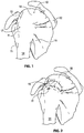
- Six muscles extend between the humerus and scapula and actuate the glenohumeral joint. These six muscles include the deltoid, the teres major, and the four rotator cuff muscles. As disclosed by Ball et al. in U.S. Patent Publication No. U.S. 2008/0188936 A1 and as illustrated in Figure 1 the rotator cuff muscles are a complex of four muscles.
- the rotator cuff muscles provide a wide variety of moments to rotate the humerus and to oppose unwanted components of the deltoid and pectoralis muscle forces.
- the four muscles of the rotator cuff arise from the scapula 12.
- the distal tendons of the rotator cuff muscles splay out and interdigitate to form a common continuous insertion on the humerus 14.
- the subscapularis 16 arises from the anterior aspect of the scapula 12 and attaches over much of the lesser tuberosity of the humerous.
- the supraspinatus muscle 18 arises from the supraspinatus fossa of the posterior scapula, passes beneath the acromion and the acromioclavicular joint, and attaches to the superior aspect of the greater tuberosity 11.
- the infraspinatus muscle 13 arises from the infraspinous fossa of the posterior scapula and attaches to the posterolateral aspect of the greater tuberosity 11.
- the teres minor 15 arises from the lower lateral aspect of the scapula 12 and attaches to the lower aspect of the greater tuberosity 11.
- the mechanics of the rotator cuff muscles 10 are complex.
- the rotator cuff muscles 10 rotate the humerus 14 with respect to the scapula 12, compress the humeral head 17 into the glenoid fossa providing a critical stabilizing mechanism to the shoulder (known as concavity compression), and provide muscular balance.
- the supraspinatus and infraspinatus provide 45 percent of abduction and 90 percent of external rotation strength.
- the supraspinatus and deltoid muscles are equally responsible for producing torque about the shoulder joint in the functional planes of motion.
- the rotator cuff muscles 10 are critical elements of this shoulder muscle balance equation.
- the human shoulder has no fixed axis. In a specified position, activation of a muscle creates a unique set of rotational moments.
- the anterior deltoid can exert moments in forward elevation, internal rotation, and cross-body movement. If forward elevation is to occur without rotation, the cross-body and internal rotation moments of this muscle must be neutralized by other muscles, such as the posterior deltoid and infraspinatus.
- the timing and magnitude of these balancing muscle effects must be precisely coordinated to avoid unwanted directions of humeral motion.
- This detachment may be partial or full, depending upon the severity of the injury. Additionally, the strain or tear can occur within the tendon itself. Injuries to the supraspinatus tendon 19 and recognized modalities for treatment are defined by the type and degree of tear.
- the first type of tear is a full thickness tear as also depicted in Figure 2 , which as the term indicates is a tear that extends through the thickness of the supraspinatus tendon regardless of whether it is completely torn laterally.
- the second type of tear is a partial thickness tear which is further classified based on how much of the thickness is torn, whether it is greater or less than 50% of the thickness.
- the accepted treatment for a full thickness tear or a partial thickness tear greater than 50% includes reconnecting the torn tendon via sutures.
- the tear is completed to a full thickness tear by cutting the tendon prior to reconnection.
- the treatment for a partial thickness tear less than 50% usually involves physical cessation from use of the tendon, i.e., rest.
- Specific exercises can also be prescribed to strengthen and loosen the shoulder area.
- the shoulder does not heal and the partial thickness tear can be the source of chronic pain and stiffness. Further, the pain and stiffness may cause restricted use of the limb which tends to result in further degeneration or atrophy in the shoulder.
- Surgical intervention may be required for a partial thickness tear of less than 50%, however, current treatment interventions do not include repair of the tendon, rather the surgical procedure is directed to arthroscopic removal of bone to relieve points of impingement or create a larger tunnel between the tendon and bone that is believed to be causing tendon damage.
- degenerated tendon may also be removed using a debridement procedure in which tendon material is ablated. Again, the tendon partial tear is not repaired.
- Several authors have reported satisfactory early post operative results from these procedures, but over time recurrent symptoms have been noted. In the event of recurrent symptoms, many times a patient will "live with the pain".
- a tendon repair would then need to be done in a later procedure if the prescribed treatment for partial tear was unsuccessful in relieving pain and stiffness or over time the tear propagated through injury or degeneration to a full thickness tear or a partial thickness tear greater than 50% with attendant pain and debilitation.
- a subsequent later procedure would include the more drastic procedure of completing the tear to full thickness and suturing the ends of the tendon back together. This procedure requires extensive rehabilitation, has relatively high failure rates and subjects the patient who first presented and was treated with a partial thickness tear less than 50% to a second surgical procedure.
- the implant delivery system includes a delivery shaft, an implant expander, a sheath, and a sheet-like implant.
- the delivery shaft has a proximal end and a distal end.
- the implant expander is mounted to the distal end of the delivery shaft.
- the implant expander includes a central portion and a plurality of leg portions radiating from the central portion.
- the implant expander is evertable between an unstressed configuration in which a distal surface of the implant expander defines a concave surface, and a first compact configuration in which the distal surface of the implant expander defines a convex surface.
- the implant expander has a first lateral extent when the implant expander is free to assume the unstressed configuration.
- the sheath defines a lumen having a lumen diameter. At least a portion of the delivery shaft is slidably disposed in the lumen. The lumen diameter is smaller than the first lateral extent of the implant expander so that the sheath holds the implant expander in the first compact configuration when slidably disposed therein.
- the sheet-like implant overlays at least a portion of the distal surface of the implant expander with portions of the sheet-like implant extending between the leg portions of the implant expander and the sheath.
- a free end of each leg portion of the implant expander is disposed distally of the central portion when the implant expander is assuming the unstressed configuration.
- the free end of each leg portion is disposed proximally of the central portion when the implant expander is assuming the first compact configuration.
- the delivery shaft distal end may be fixed to the central portion of the implant expander to urge relative movement between the implant expander and the sheath such that the implant expander and the sheet-like implant can be advanced through a distal opening defined by the sheath so the implant expander is free to assume a deployed configuration.
- a projection extends distally from the distal surface of the central portion of the implant expander to hold the position of delivery system when the projection is held against a target tissue.
- the implant expander may generally conform to the surface of a target tissue when the implant expander assumes the deployed configuration.
- the distal surface of the implant expander defines a concave surface when the implant expander is assuming the deployed configuration and the target tissue has a generally convex shape.
- a free end of each leg portion may be disposed distally of the central portion when the implant expander is assuming the deployed configuration and the target tissue has a generally convex shape.
- the implant expander causes the sheet-like implant to conform to the surface of a target tissue when the implant expander assumes the deployed configuration.
- the implant expander assumes a second compact configuration when the implant expander is retracted proximally into the lumen of the sheath after having assumed the deployed configuration.
- the distal surface of the implant expander may define a concave surface when the implant expander is assuming the second compact configuration.
- the free end of each leg portion is disposed distally of the central portion when the implant expander is assuming the second compact configuration.
- the implant expander is integrally formed of a single material.
- the sheet-like implant may define a plurality of pockets. Each pocket may be dimensioned to receive a distal portion of a leg portion of the implant expander.
- the sheet-like implant can be selectively separated from the implant expander by withdrawing the distal portions of the legs from the pockets.
- the implant expander further includes a plurality of retainers to engage the sheet-like implant such that the sheet-like implant moves when the implant expander is moved.
- the sheet-like implant can be selectively separated from the implant expander by withdrawing the retainers from the sheet-like implant.
- the method includes the steps of providing an implant delivery system, inflating the shoulder to create a cavity therein, placing the sheet-like implant and the implant expander inside the cavity, allowing the implant expander to assume a deployed configuration, attaching the sheet-like implant to the tendon, urging the implant expander to assume a second compact configuration, and removing the implant expander from the cavity.
- the implant delivery system that is provided includes an implant expander.
- the implant expander has a central portion and a plurality of leg portions radiating from the central portion.
- the implant expander is evertable between an unstressed configuration in which a distal surface of the implant expander defines a concave surface, and a first compact configuration in which the distal surface of the implant expander defines a convex surface.
- a sheet-like implant overlays at least a portion of the distal surface of the implant expander.
- a sheath is disposed about the sheet-like implant and the implant expander. The sheath holds the implant expander in the first compact configuration.
- the implant expander urges the sheet-like implant against a surface of the tendon.
- the distal surface of the implant expander defines a concave surface.
- the implant expander includes a projection extending distally from its central portion. The projection holds the position of the delivery system relative to the tendon when the sheet-like implant and implant expander are placed in the cavity against the tendon.
- the step of allowing the implant expander to assume the deployed configuration includes urging relative movement between the implant expander and the sheath such that the implant expander and the sheet-like implant are advanced through a distal opening defined by the sheath. With this arrangement, the implant expander is free to assume the deployed configuration.
- urging relative movement between the implant expander and the sheath includes withdrawing the sheath in a proximal direction relative to the implant expander.
- urging relative movement between the implant expander and the sheath includes advancing the implant expander in a distal direction along the lumen of the sheath.
- urging the implant expander to assume the second compact configuration includes advancing the sheath over the implant expander so that the implant expander is disposed inside the lumen defined by the sheath. In some embodiments, urging the implant expander to assume the second compact configuration includes drawing the implant expander proximally into the lumen defined by the sheath. In some embodiments, urging the implant expander to assume the second compact configuration includes drawing the implant expander and the projection that extends distally from the central portion of the implant expander proximally into the lumen defined by the sheath.
- methods of preparing a delivery system include the steps of providing a delivery sheath and an implant expander, covering at least a portion of the distal surface with a sheet-like implant, and deflecting the implant expander.
- the sheath defines a lumen having a lumen diameter.
- the implant expander includes a central portion and a plurality of leg portions radiating from the central portion. The implant expander is evertable between an unstressed configuration in which a distal surface of the implant expander defines a concave surface, and a first compact configuration in which the distal surface of the implant expander defines a convex surface.
- the implant expander has a first lateral extent when the implant expander is free to assume the unstressed configuration.
- the first lateral extent is greater than the lumen diameter of the sheath.
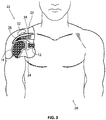
- Figure 3 is a stylized anterior view of a patient 20.
- a shoulder 22 of patient 20 is shown in cross-section in Figure 3 .
- Shoulder 22 includes a humerus 14 and a scapula 12.
- a head 24 of humerus 14 can be seen mating with a glenoid fossa of scapula 12 at a glenohumeral joint.
- the glenoid fossa comprises a shallow depression in scapula 12.
- humerus 14 relative to scapula 12 is controlled by a number of muscles including: the deltoid, the supraspinatus, the infraspinatus, the subscapularis, and the teres minor.
- the supraspinatus 26 is shown in Figure 3 .
- Scapula 12 of shoulder 22 includes an acromium 32.
- a subacromial bursa 34 is shown extending between acromium 32 of scapula 12 and head 24 of humerus 14.
- subacromial bursa 34 is shown overlaying supraspinatus 26.
- Subacromial bursa 34 is one of the hundreds of bursae found the human body. Each bursa comprises a fluid filled sac. The presence of these bursae in the body reduces friction between bodily tissues. Injury and/or infection of the bursa can cause it to become inflamed. This condition is sometimes referred to as bursitis.
- a tendon repair implant may be fixed to one or more tendons associated with an articulating joint, such as the glenohumeral joint.
- the tendons to be treated may be torn, partially torn, have internal micro-tears, be untorn, and/or be thinned due to age, injury or overuse.
- the methods and apparatus of the present application and related devices may provide very beneficial therapeutic effect on a patient experiencing joint pain believed to be caused by partial thickness tears and/or internal microtears.
- the implant may cause the tendon to thicken and/or at least partially repair itself, thereby avoiding more extensive joint damage, pain, and the need for more extensive joint repair surgery.
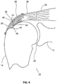
- Figure 4 is a stylized anterior view of a shoulder 22 including a humerus 14 and a scapula 12.
- a head 24 of humerus 14 is shown mating with a glenoid fossa of scapula 12 at a glenohumeral joint.
- a supraspinatus 26 is also shown in Figure 4 . This muscle, along with others, control the movement of humerus 14 relative to scapula 12.
- a distal tendon 28 of supraspinatus 26 meets humerus 14 at an insertion point 30.
- distal tendon 28 includes a first damaged portion 36.
- a number of loose tendon fibers 40 in first damaged portion 36 are visible in Figure 4 .
- First damaged portion 36 includes a first tear 42 extending partially through distal tendon 28.
- First tear 42 may therefore be referred to as a partial thickness tear.
- first tear 42 begins on the side of distal tendon 28 facing the subacromial bursa (shown in the previous Figure) and ends midway through distal tendon 28. Accordingly, first tear 42 may be referred to as a bursal side tear.
- distal tendon 28 includes a second damaged portion 38 located near insertion point 30.
- second damaged portion 38 of distal tendon 28 has become frayed and a number of loose tendon fibers 40 are visible in Figure 4 .
- Second damaged portion 38 of distal tendon 28 includes second tear 44.
- second tear 44 begins on the side of distal tendon 28 facing the humerus 14. Accordingly, second damaged portion 38 may be referred to as an articular side tear.
- a sheet-like implant 50 has been placed over the bursal side of distal tendon 28.
- sheet-like implant 50 extends over insertion point 30, first tear 42 and second tear 44.
- Some useful methods in accordance with this detailed description may include placing a tendon repair implant on the bursal side of a tendon regardless of whether the tears being treated are on the bursal side, articular side or within the tendon. In some cases the exact location and nature of the tears being treated may be unknown.
- a tendon repair implant may be applied to the bursal side of a tendon to treat shoulder pain that is most likely caused by one or more partial thickness tears in the tendon.
- sheet-like implant 50 is fixed to distal tendon 28 by a plurality of staples.
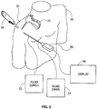
- Figure 5 is a stylized perspective view illustrating an exemplary procedure for treating a shoulder 22 of a patient 20.
- the procedure illustrated in Figure 5 may include, for example, fixing tendon repair implants to one or more tendons of shoulder 22.
- the tendons treated may be torn, partially torn, have internal micro-tears, be untorn, and/or be thinned due to age, injury or overuse.
- a fluid supply 52 is pumping a continuous flow of saline into the cavity. This flow of saline exits the cavity via a fluid drain 54.
- a camera 56 provides images from inside the cavity. The images provided by camera 56 may be viewed on a display 58.
- Camera 56 may be used to visually inspect the tendons of shoulder 22 for damage.
- a tendon repair implant in accordance with this disclosure may be fixed to a bursal surface of the tendon regardless of whether there are visible signs of tendon damage.
- the methods and apparatus of the present application and related devices may provide very beneficial therapeutic effect on a patient experiencing joint pain believed to be caused by internal microtears, but having no clear signs of tendon tears.
- the implant may cause the tendon to thicken and/or at least partially repair itself, thereby avoiding more extensive joint damage, pain, and the need for more extensive joint repair surgery.
- a delivery system 60 can be seen extending from shoulder 22 in Figure 5 .
- Delivery system 60 comprises a sheath that is fixed to a handle.
- the sheath defines a lumen and a distal opening fluidly communicating with the lumen.
- the distal opening of the sheath has been placed in fluid communication with the cavity created in shoulder 22.
- a tendon repair implant is at least partially disposed in the lumen defined by the sheath of delivery system 60.
- Delivery system 60 can be used to place the tendon repair implant inside shoulder 22. Delivery system 60 can also be used to hold the tendon repair implant against the tendon.
- the tendon repair implant is folded into a compact configuration when inside the lumen of the sheath. When this is the case, delivery system 60 may be used to unfold the tendon repair implant into an expanded shape.
- the tendon repair implant may be fixed to the tendon while it is held against the tendon by delivery system 60.
- Various attachment elements may be used to fix the tendon repair implant to the tendon. Examples of attachment elements that may be suitable in some applications include sutures, tissue anchors, bone anchors, and staples.
- the shaft of a fixation tool 70 is shown extending into shoulder 22.
- fixation tool 70 is capable of fixing the tendon repair implant to the tendon with one or more staples while the tendon repair implant is held against the tendon by delivery system 60.
- Figure 6 is an enlarged perspective view further illustrating the procedure shown in the previous Figure.
- Figure 6 also illustrates the interior structure of shoulder 22 shown in the previous Figure.
- shoulder 22 includes a humerus 14 and a scapula 12.
- a head 24 of humerus 14 is shown mating with a glenoid fossa of scapula 12 at a glenohumeral joint.
- a supraspinatus 26 is also shown in Figure 6 .
- a distal tendon 28 of supraspinatus 26 can be seen meeting a tuberosity of humerus 14 in Figure 6 .
- Delivery system 60 is also shown in Figure 6 .
- a distal end of delivery system 60 has been positioned near distal tendon 28 of supraspinatus 26.
- Delivery system 60 comprises a sheath 102 that is fixed to a handle 104.
- Sheath 102 defines a lumen 108 and a distal opening fluidly communicating with the lumen.
- a central portion of a sheet-like implant 50 can be seen extending through the distal opening defined by sheath 102.
- sheet-like implant 50 is overlaying an implant expander.
- the implant expander and sheet-like implant 50 are both assuming a compact configuration.
- the majority of sheet-like implant 50 is disposed inside sheath 102.
- a central portion of sheet-like implant 50 is extending out of sheath 102. This central portion of sheet-like implant 50 is contacting an outer surface of distal tendon 28 in the embodiment of Figure 6 .
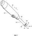
- FIG 7 is an enlarged perspective view showing delivery system 60 shown in the previous Figure.
- sheath 102 of delivery system 60 has been moved in a proximal direction P relative to handle 104.
- sheet-like implant 50 and implant expander 120 are now disposed outside of lumen 108 defined by sheath 102.
- Implant expander 120 comprises a central portion 122 and a plurality of leg portions 124 radiating from central portion 122.
- leg portions 124 of implant expander 120 are shown overlaying sheet-like implant 50.
- Hub 126 is shown overlaying central portion 122 of implant expander 120 in Figure 7 .
- Implant expander 120 can be used to expand sheet-like implant 50 and hold sheet-like implant 50 against the surface of a target tissue. Sheet-like implant 50 may be fixed to the target tissue while the implant is held against the target tissue by implant expander 120.
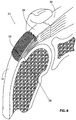
- Figure 8 is a stylized perspective view of a shoulder 22 including a supraspinatus 26 having a distal tendon 28.
- a tendon repair implant 50 has been fixed to a surface of distal tendon 28.
- Tendon repair implant 50 may comprise, for example, various sheet-like structures without deviating from the spirit and scope of the present detailed description.
- the sheet-like structure may comprise a plurality of fibers. The fibers may be interlinked with one another. When this is the case, the sheet-like structure may comprise a plurality of apertures comprising the interstitial spaces between fibers.
- Various processes may be used to interlink the fibers with one another.
- the sheet-like structure may comprise a laminate including multiple layers of film with each layer of film defining a plurality of micro-machined or formed holes.
- the sheet-like structure of the tendon repair implant may also comprise a plurality of electro-spun nanofiber filaments forming a composite sheet.
- the sheet-like structure may comprise a synthetic sponge material that defines a plurality of pores.
- the sheet-like structure may also comprise a reticulated foam material. Reticulated foam materials that may be suitable in some applications are available from Biomerix Corporation of Fremont, California which identifies these materials using the trademark BIOMATERIALTM.
- the sheet-like structure may be circular, oval, oblong, square, rectangular, or other shape con Figured to suit the target anatomy.
- attachment elements may be used to fix tendon repair implant 50 to distal tendon 28 without deviating from the spirit and scope of this detailed description.
- attachment elements that may be suitable in some applications include sutures, tissue anchors, bone anchors, and staples.
- a plurality of staples are fixing tendon repair implant 50 to distal tendon 28.
- a plurality of staples may be applied using a fixation tool. The fixation tool may then be withdrawn from the body of the patient. Distal tendon 28 meets humerus 14 at an insertion point 30.
- sheet-like implant 50 extends over insertion point 30.
- Tendon repair implant may be applied to distal tendon 28, for example, using the procedure illustrated in the previous Figure.
- staples may straddle the perimeter edge of the sheet-like implant (as shown in Figure 8 ), may be applied adjacent to the perimeter, and/or be applied to a central region of the implant.
- the staples may be used to attach the implant to soft tissue and/or to bone.
- FIG 9 is an additional perspective view further illustrating delivery system 60.
- Delivery system 60 comprises a sheath 102 that is fixed to a handle 104.
- Sheath 102 defines a lumen 108 and a distal opening 128 fluidly communicating with lumen 108.
- a delivery aid 130 can be seen extending through distal opening 128 defined by sheath 102.
- delivery aid 130 comprises a hub 126 that is disposed at the distal end of a control rod 132.
- An implant expander 120 is attached to hub 126.
- Implant expander 120 comprises a central portion 122 and a plurality of leg portions 124 radiating from central portion 122.
- a sheet-like implant 50 is shown overlaying a distal surface of implant expander 120.
- implant expander 120 is urging sheet-like implant 50 against a generally spherical surface (not shown in Figure 9 ).
- Sheath 102 of delivery system 60 is coupled to a button 134. It will be appreciated that various other operative mechanisms may be used in addition to button 134. Relative motion between button 134 and handle 104 will cause similar relative motion between sheath 102 and handle 104. In the exemplary embodiment of Figure 9 , sheath 102 will be moved distally (relative to handle 104) when button 134 is moved distally (relative to handle 104). Additionally, sheath 102 will be moved proximally (relative to handle 104) when button 134 is moved proximally (relative to handle 104).
- implant expander 120 is shown residing outside of lumen 108 defined by sheath 102. In Figure 9 , implant expander 120 is shown assuming a deployed configuration. Implant expander 120 can be selectively urged to assume a compact configuration, for example, by placing implant expander inside lumen 108 defined by sheath 102. Implant expander can be placed inside lumen 108, for example, by advancing sheath 102 over implant expander 120.
- Figure 10A through Figure 10E are a series of stylized plan views illustrating an exemplary method in accordance with the present detailed description.
- Figure 10A through Figure 10E may be referred to collectively as Figure 10 .
- a proximal direction is illustrated with an arrow P in Figure 10 .
- a distal direction is illustrated with another arrow D in Figure 10 .
- the exemplary method of Figure 10 may be used, for example, to fix a sheet-like implant 50 to a surface 136 of a target tissue 138.
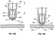
- FIG 10A is a partial cross-sectional view illustrating a distal portion of a delivery system 60 in accordance with this detailed description.
- Delivery system 60 comprises a sheath 102 that is fixed to a handle.
- Sheath 102 defines a lumen 108 and a distal opening fluidly communicating with the lumen.
- a central portion of a sheet-like implant 50 can be seen extending through the distal opening defined by sheath 102.
- sheet-like implant 50 is overlaying an implant expander.
- the implant expander and sheet-like implant 50 are both assuming a compact configuration. With reference to Figure 10 , it will be appreciated that the majority of sheet-like implant 50 is disposed inside sheath 102.
- a central portion of a sheet-like implant 50 is extending out of sheath 102.
- Implant expander 120 of Figure 10 comprises a central portion 122 and a plurality of leg portions 124 radiating from central portion 122.
- implant expander 120 is assuming a first compact configuration.
- the free end of each leg portion 124 is disposed proximally of central portion 122 when implant expander 120 is assuming the first compact configuration.
- a distal surface 140 of implant expander 120 defines a convex surface when implant expander 120 is assuming the first compact configuration 142.
- Portions of sheet-like implant 50 can be seen extending between leg portions 124 of implant expander 120 and the wall of sheath 102.
- a fold 146 comprising a portion of sheet-like implant 50 can also be seen extending between an adjacent pair of leg portions 124.
- a central portion of sheet-like implant 50 is trapped between implant expander 120 and surface 136 of target tissue 138.
- sheet-like implant 50 has been advanced distally so that central portion of sheet-like implant 50 is contacting surface 136 of target tissue 138.
- delivery system 60 includes a projection 148 extending distally from distal surface 140 of central portion 122 of implant expander 120.
- projection 148 may be used to temporarily hold the position of delivery system 60 while sheet-like implant 50 is held against surface 136 of target tissue 138.
- projection 148 comprises a spike 150 having a generally cone-like shape.
- spike 150 has been advanced so that a distal portion of spike 150 has pierced target tissue 138.
- Spike 150 can be seen extending through sheet-like implant 50 in Figure 10B .
- Spike 150 may be used to temporarily center implant expander 120 and sheet-like implant 50 on a target location. Once sheet-like implant 50 has been fixed to target tissue 138, spike 150 can be withdrawn from target tissue 138 and sheet-like implant 50.
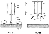
- implant expander 120 of delivery system 60 is shown assuming a deployed configuration.
- leg portions 124 of implant expander 120 are conforming to the shape of surface 136.
- surface 136 has a generally planar shape.
- Sheet-like implant 50 is resting between implant expander 120 and surface 136 of target tissue 138, with sheet-like implant 50 overlaying surface 136.
- implant expander 120 is causing sheet-like implant 50 to generally conform to the shape of surface 136.
- implant expander 120 of delivery system 60 is shown assuming an unstressed configuration.
- implant expander 120 has been lifted in proximal direction P.
- no external forces are acting on leg portions 124 and implant expander 120 is free to assume the unstressed configuration shown in Figure 10D .
- the free end of each leg portion 124 is disposed distally of central portion 122 when implant expander 120 is assuming the unstressed configuration.
- the distal surface 140 of implant expander 120 defines a concave surface when implant expander 120 is assuming the unstressed configuration.
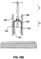
- implant expander 120 of delivery system 60 is shown assuming a second compact configuration.
- implant expander 120 and sheath 102 have been moved relative to each other.
- implant expander 120 may be urged to assume the second compact configuration moving implant expander 120 and sheath 102 relative to one another so that implant expander 120 is disposed in lumen 108 defined by sheath 102.
- the free end of each leg portion 124 is disposed distally of central portion 122 when implant expander 120 is assuming the second compact configuration 144.
- the distal surface 140 of implant expander 120 defines a concave surface when implant expander 120 is assuming the second compact configuration 144.
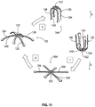
- Figure 11 is a stylized diagram illustrating four configurations of an exemplary implant expander 120. The step of transitioning between one configuration and another configuration is represented by three arrows in Figure 11 . A proximal direction is illustrated with another arrow P in Figure 11 . A distal direction is illustrated with an additional arrow D in Figure 11 .
- Implant expander 120 of Figure 11 comprises a central portion 122 and a plurality of leg portions 124 radiating from central portion 122.
- a first arrow 1 represents a transition between a first compact configuration 142 and a deployed configuration 154.
- the free end of each leg portion 124 is disposed proximally of central portion 122 when implant expander 120 is assuming the first compact configuration 142.
- a distal surface 140 of implant expander 120 defines a convex surface when implant expander 120 is assuming the first compact configuration 142.
- implant expander 120 is held in the first compact configuration 142 while implant expander 120 is disposed in a lumen of a sheath.
- implant expander 120 may be allowed to assume deployed configuration 154 when the sheath is retracted from around implant expander 120. Implant expander 120 may also be allowed to assume deployed configuration 154 when implant expander 120 is moved in a distal direction so that implant expander 120 exits the lumen via a distal opening of the sheath or when the sheath moves proximally to reveal the implant expander from within the distal opening of the sheath and relieve stress within leg portions 124.
- leg portions 124 of implant expander 120 conform to the shape of a target tissue when implant expander 120 is in the deployed configuration.
- implant expander 120 is shown conforming to the shape of a generally planar surface (not shown in Figure 11 ) while implant expander is assuming the deployed configuration.
- a second arrow 2 represents a transition between the deployed configuration 154 and an unstressed configuration 152.
- implant expander 120 is free to assume unstressed configuration 152 when implant expander 120 is lifted off of a target surface so that no external forces are acting on leg portions 124 of implant expander 120.
- each leg portion 124 is disposed distally of central portion 122 when implant expander 120 is assuming unstressed configuration 152.
- distal surface 140 of implant expander 120 defines a concave surface when implant expander 120 is assuming the unstressed configuration 152.
- a third arrow 3 represents a transition between the unstressed configuration 152 and a second compact configuration 144.
- implant expander 120 is urged to assume second compact configuration 144 by drawing implant expander 120 proximally into a lumen of a sheath.
- the free end of each leg portion 124 is disposed distally of central portion 122 when implant expander 120 is assuming the second compact configuration 144.
- the distal surface 140 of implant expander 120 defines a concave surface when implant expander 120 is assuming the second compact configuration 144.
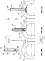
- FIG 12 is a perspective view illustrating an exemplary delivery system 360.
- Delivery system 360 comprises a sheath 302 that is fixed to a handle 304.
- Sheath 302 defines a lumen 308 and a distal opening 328 fluidly communicating with lumen 308.
- a delivery aid 330 can be seen extending through distal opening 328 defined by sheath 302.
- delivery aid 330 comprises a hub 326 that is disposed at the distal end of a control rod 332.
- An implant expander 320 is attached to hub 326.
- Implant expander 320 comprises a central portion 322 and a plurality of leg portions 324 radiating from central portion 322.
- Sheath 302 of delivery system 360 is coupled to an actuator 356. Relative motion between actuator 356 and handle 304 will cause similar relative motion between sheath 302 and handle 304. In the exemplary embodiment of Figure 12 , sheath 302 will be moved distally (relative to handle 304) when actuator 356 is moved distally (relative to handle 304). Additionally, sheath 302 will be moved proximally (relative to handle 304) when actuator 356 is moved proximally (relative to handle 304).
- implant expander 320 is shown residing outside of lumen 308 defined by sheath 302.
- implant expander 320 is shown assuming an unstressed configuration.
- Implant expander 320 can be selectively urged to assume a compact configuration, for example, by placing implant expander inside lumen 308 defined by sheath 302.
- Implant expander can be placed inside lumen 308, for example, by advancing sheath 302 over implant expander 320.
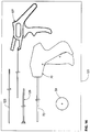
- Figure 13 is a plan view illustrating an exemplary assembly in accordance with the present detailed description.
- the assembly of Figure 13 includes a sheet-like implant 50 and an implant expander 520.
- Implant expander 520 of Figure 13 comprises a central portion 522 and a plurality of leg portions 524 radiating from central portion 522.
- a sheet-like implant 50 is trapped between implant expander 520 and a target tissue 538.
- implant expander 520 includes a plurality of retainers 558.
- retainers 558 engage sheet-like implant 50 so that sheet-like implant 50 moves when implant expander 520 is moved and may aid in imparting lateral stress of the legs into lateral stress within the implant.
- Figure 14 is a plan view illustrating an exemplary assembly in accordance with the present detailed description.
- the assembly of Figure 14 includes a sheet-like implant 50 and an implant expander 720.
- Implant expander 720 of Figure 14 comprises a central portion 722 and a plurality of leg portions 724 radiating from central portion 722.
- a sheet-like implant 50 is trapped between implant expander 720 and a target tissue 738.
- sheet-like implant 50 includes a plurality of pockets 762.
- each pocket 762 is dimensioned to receive the end of a leg portion 724 of implant expander 720.
- implant expander 720 engages pockets 762 so that sheet-like implant 50 moves when implant expander 720 is moved.
- Figure 15A through Figure 15F are a series of stylized plan views illustrating an exemplary method in accordance with the present detailed description.
- Figure 15A through Figure 15F may be referred to collectively as Figure 15 .
- a proximal direction is illustrated with an arrow P in Figure 15 .
- a distal direction is illustrated with another arrow D in Figure 15 .
- the exemplary method of Figure 15 may be used, for example, to fix a sheet-like implant 50 to a surface of a target tissue 138.
- Figure 15A is a stylized plan view of illustrating a shoulder 22 of a patient. Shoulder 22 of Figure 15A has been inflated to create a cavity 62 therein.
- a fluid supply 64 is pumping a continuous flow of saline into cavity 62. This flow of saline exits cavity 62 via a fluid drain 66.
- a sheath 102 of a delivery system 60 is shown positioned near a shoulder 22.
- Delivery system 60 also comprises a delivery aid 130 including an implant expander that is fixed to the distal end of a control rod 132.
- a sheet-like implant 50 is overlaying the implant expander of delivery aid 130.
- delivery aid 130 includes a projection 148 extending distally from the implant expander.
- projection 148 comprises a spike 150 having a generally cone-like shape. Spike 150 can be seen extending through sheet-like implant 50 in Figure 15A . Spike 150 may be used to temporarily center sheet-like implant 50 on a target location. Once sheet-like implant 50 has been fixed to target tissue 138, spike 150 can be withdrawn from target tissue 138 and sheet-like implant 50.
- Delivery aid 130 can be used to insert sheet-like implant 50 into cavity 62 formed in shoulder 22. Delivery aid 130 can also be used to hold the sheet-like implant against a target tissue 138. In some embodiments, the sheet-like implant is folded into a compact configuration when inside the lumen of the sheath. When this is the case, delivery aid 130 may be used to unfold the sheet-like implant into an expanded shape.
- FIG 15B sheath 102 is shown extending into shoulder 22. A distal opening of sheath 102 has been placed in fluid communication with cavity 62 in the embodiment of Figure 15B .
- sheet like implant 50 has been advanced distally so that a central portion of sheet like implant 50 is contacting a surface of target tissue 138. The central portion of sheet like implant 50 is trapped between implant expander 120 and the surface of target tissue 138 in the embodiment of Figure 15B .
- Implant expander 120 of delivery aid 130 is shown assuming a deployed configuration.
- Implant expander 120 of Figure 15 comprises a central portion 122 and a plurality of leg portions 124 radiating from central portion 122.
- implant expander 120 is assuming a deployed configuration.
- Implant expander 120 is fixed to the distal end of control rod 132 in the embodiment of Figure 15 .
- Sheet like implant 50 is shown overlaying an outer surface of target tissue 138 in Figure 15C .
- sheet like implant 50 is generally conforming to the shape of target tissue 138.
- Implant expander 120 is holding sheet-like implant 50 against target tissue 138 in the embodiment of Figure 15C .
- Some exemplary methods in accordance with this detailed description include the steps of inflating a shoulder to create a cavity therein and placing a distal opening of a sheath in fluid communication with the cavity while the sheath is surrounding a delivery device disposed inside a lumen thereof and the sheath is maintaining the delivery device in a first compact configuration.
- a central portion of the sheet-like material may be placed in contact with a surface of a target tissue.
- the sheath may be withdrawn from around the delivery device so that the delivery device is free to assume a deployed configuration inside the cavity.
- the delivery device may be used to hold the sheet-like material against a surface of the target tissue while the delivery device is assuming the deployed configuration.
- the sheet-like implant 50 may be fixed to the target tissue while sheet-like implant 50 is held against the surface of the target tissue.
- the delivery device may be urged to assume a second compact configuration as the delivery device is removed from the cavity.
- a fixation tool shaft 72 of a fixation tool 70 is shown extending into shoulder 22.
- a distal end of fixation tool shaft 72 is disposed proximate an edge of sheet like implant 50.
- One or more staples may be disposed inside fixation tool shaft 72.
- Fixation tool 70 may apply staples to fix sheet like implant 50 to target tissue 138 while sheet like implant 50 is held in place by implant expander 120.
- attachment elements may be used to fix sheet like implant 50 to target tissue 138 without deviating from the spirit and scope of this detailed description.
- attachment elements that may be suitable in some applications include sutures, tissue anchors, bone anchors, and staples.
- sheet like implant 50 is fixed to target tissue 138 by a plurality of staples 74.
- a plurality of staples may be applied using a fixation tool. The fixation tool may then be withdrawn from the body of the patient.
- delivery aid 130 may be used to hold sheet like implant 50 against target tissue 138 while staples 74 are applied using fixation tool 70.
- Implant expander 120 of delivery aid 130 has been urged to assume a second compact configuration in the embodiment of Figure 15F .
- Implant expander 120 comprises a central portion 122 and a plurality of leg portions 124 radiating from central portion 122.
- the free end of each leg portion is disposed distally of central portion 122 when implant expander 120 is assuming the second compact configuration.
- kit 123 comprises a sheet-like implant 50 and a number of tools that may be used in conjunction with sheet-like implant 50.
- the tools of kit 123 may be used, for example, for delivering sheet-like implant 50 to a target location within the body of a patient. These tools may also be used, for example, for fixing sheet-like implant 50 to a target tissue.
- kit 123 comprises a locating guide 125, a locating guide removal tool 127, a fixation tool 70, and a delivery aid 129.
- locating guide 125 includes a temporary fixation mechanism proximate its distal end.
- a method in accordance with the present detailed description may include temporarily fixing the distal end of locating guide 125 to a target tissue and advancing sheet-like implant 50 over locating guide 125 for delivering the sheet-like implant to the target location.
- delivery aid 129 may be used for advancing sheet-like implant 50 over locating guide 125 and urging sheet-like implant 50 against a target tissue.
- Fixation tool 70 of kit 123 may be used, for example, for fixing sheet-like implant 50 to the target tissue.
- Locating guide removal tool 127 may be used to remove locating guide 125 after sheet-like implant 50 has been fixed to the target tissue.
- fixation tool 70 includes a fixation tool shaft 72.
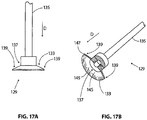
- Figure 17A is an enlarged plan view illustrating delivery aid 129 shown in the previous Figure.
- Figure 17B is a partial cross-sectional perspective view further illustrating delivery aid 129.
- Figure 17A and Figure 17B may be collectively referred to as Figure 17 .
- a distal direction is illustrated with an arrow D in Figure 17 .
- delivery aid 129 includes an implant expander 133 fixed to a distal end of a control rod 135.
- Implant expander 133 of Figure 17 has a central portion 137 and an outer portion 139 extending radially from central portion 137.
- no external forces are acting on implant expander 133 and implant expander 133 is free to assume an unstressed configuration.
- a distal surface 143 of implant expander 133 comprises a generally concave surface 145 when the implant expander is assuming an unstressed configuration.
- an outermost edge 147 of outer portion 139 is disposed distally of central portion 137 when implant expander 133 is assuming the unstressed configuration.
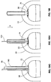
- Figure 18A through Figure 18I are a series of stylized plan views illustrating an exemplary method in accordance with the present detailed description.
- Figure 18A through Figure 18I may be referred to collectively as Figure 18 .
- a proximal direction is illustrated with an arrow P in Figure 18 .
- a distal direction is illustrated with another arrow D in Figure 18 .
- the exemplary method of Figure 18 may be used, for example, to fix a sheet-like implant 50 to a surface of a target tissue 138.
- a cannula 149 is shown extending into a shoulder 22.
- Cannula 149 defines a lumen 153.
- a distal end of cannula 149 is located proximate a target tissue 138.
- the distal end of cannula 149 defines a distal opening that fluidly communicates with lumen 153.
- a locating guide 125 is shown extending through lumen 153 defined by cannula 149. Some methods in accordance with the present disclosure may include the step of advancing the distal end of a locating guide through a cannula.
- a distal portion of locating guide 125 is disposed in target tissue 138.
- the distal portion of locating guide 125 includes a barb. When this is the case, the barb may help maintain the position of the distal end of locating guide 125 in the target tissue.
- a sheet-like implant 50 is shown disposed about locating guide 125.
- Some methods in accordance with the present disclosure may include the step of inserting a locating guide through a sheet-like implant. Some of these methods may also include the step of advancing the sheet-like implant over the locating guide toward a target tissue.
- a delivery aid 129 is shown disposed about locating guide 125.
- Some methods in accordance with the present disclosure may include the step of inserting the proximal end of a locating guide 125 into a distal aperture of a delivery aid 129.
- the delivery aid 129 may be advanced over locating guide 125 for urging a sheet-like implant 50 toward a target tissue (e.g., target tissue 138).
- a target tissue e.g., target tissue 138
- delivery aid 129 may be used to urge sheet-like implant 50 in a longitudinal direction along locating guide 125.
- delivery aid 129 may also be used to hold sheet-like implant 50 against a target tissue.
- sheet-like implant 50 is disposed in a lumen 153 defined by cannula 149.
- sheet-like implant 50 has been pushed distally into lumen 153.
- sheet-like implant 50 has been folded into a compact configuration.
- Sheet-like implant 50 is shown overlaying the implant expander of delivery aid 129 in Figure 18E .
- the implant expander is urged to assume a first compact configuration as the implant expander and sheet-like implant 50 are advanced into lumen 153.
- sheet-like implant 50 is shown overlaying target tissue 138.
- Some methods in accordance with the present detailed description include the step of passing a sheet-like implant through a cannula.
- sheet-like implant 50 may be pushed through cannula 149 using delivery aid 129.
- Delivery aid 129 may also be used to hold sheet-like implant 50 against target tissue 138 while a surgeon attaches sheet-like implant 50 to target tissue 138.
- a fixation tool shaft 72 of a fixation tool 70 is shown extending through cannula 149.
- a distal end of fixation tool shaft 72 is disposed proximate sheet-like implant 50.
- One or more staples may be disposed inside fixation tool shaft 72.
- sheet-like implant 50 is fixed to target tissue 138 by a plurality of staples 74.
- a plurality of staples may be applied to a sheet-like implant and a target tissue using a fixation tool. The fixation tool may then be withdrawn from the body of the patient.
- delivery aid 129 has been withdrawn from shoulder 22 and locating guide 125 remains in the position shown in Figure 18H .
- locating guide 125 has been withdrawn from shoulder 22.
- Some useful methods in accordance with the present detailed description include the use of a locating guide including a temporary fixation mechanism located proximate its distal end. These exemplary methods may also include the use of a locating guide removal tool to aid in withdrawing the locating guide from the body of the patient.
- a plurality of staples 74 can be seen fixing sheet-like implant 50 to target tissue 138.
- FIG 19 is a plan view showing a locating guide 125.
- locating guide 125 has a point 155 at its distal end.
- locating guide 125 includes a barb 157 near its distal end.
- point 155 is shown pointing in a distal direction D and barb 157 is shown pointing in a proximal direction P.
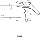
- FIG 20 is a plan view showing a locating guide removal tool 127.
- Locating guide removal tool 127 may be used, for example, to remove a locating guide 125 from a target tissue.
- locating guide removal tool 127 includes a tubular body 159 that is fixed to a grip 163. In operation, tubular body 159 is advanced over the proximal end of a locating guide so that a portion of the locating guide extends into a lumen defined by tubular body 159. Locating guide removal tool 127 may then be used to grasp a proximal portion of the locating guide and produce relative motion between the locating guide and tubular body 159.
- a lever 165 is pivotably coupled to grip 163. Relative motion between locating guide 125 and tubular body 159 can be produced by rotating lever 165 relative to grip 163 when locating guide removal tool 127 is grasping the proximal portion of locating guide 125. This relative motion can be used to advance tubular body 159 over the barb 157 of locating guide 125. Locating guide 125 may be withdrawn from the body of the patient while tubular body 159 is covering barb 157.
Applications Claiming Priority (3)
| Application Number | Priority Date | Filing Date | Title |
|---|---|---|---|
| US18419809P | 2009-06-04 | 2009-06-04 | |
| US31311610P | 2010-03-11 | 2010-03-11 | |
| EP10724216.6A EP2437686B1 (fr) | 2009-06-04 | 2010-06-04 | Appareil pour le deploiement de materiaux en feuille |
Related Parent Applications (2)
| Application Number | Title | Priority Date | Filing Date |
|---|---|---|---|
| EP10724216.6A Division EP2437686B1 (fr) | 2009-06-04 | 2010-06-04 | Appareil pour le deploiement de materiaux en feuille |
| EP10724216.6A Division-Into EP2437686B1 (fr) | 2009-06-04 | 2010-06-04 | Appareil pour le deploiement de materiaux en feuille |
Publications (1)
| Publication Number | Publication Date |
|---|---|
| EP3308743A1 true EP3308743A1 (fr) | 2018-04-18 |
Family
ID=42313933
Family Applications (2)
| Application Number | Title | Priority Date | Filing Date |
|---|---|---|---|
| EP17199011.2A Withdrawn EP3308743A1 (fr) | 2009-06-04 | 2010-06-04 | Procédés et appareil de déploiement de matériaux de type feuille |
| EP10724216.6A Active EP2437686B1 (fr) | 2009-06-04 | 2010-06-04 | Appareil pour le deploiement de materiaux en feuille |
Family Applications After (1)
| Application Number | Title | Priority Date | Filing Date |
|---|---|---|---|
| EP10724216.6A Active EP2437686B1 (fr) | 2009-06-04 | 2010-06-04 | Appareil pour le deploiement de materiaux en feuille |
Country Status (6)
| Country | Link |
|---|---|
| US (6) | US9179961B2 (fr) |
| EP (2) | EP3308743A1 (fr) |
| JP (1) | JP5718912B2 (fr) |
| AU (1) | AU2010256414C1 (fr) |
| CA (1) | CA2763937C (fr) |
| WO (1) | WO2010141906A1 (fr) |
Families Citing this family (54)
| Publication number | Priority date | Publication date | Assignee | Title |
|---|---|---|---|---|
| US8808314B2 (en) * | 2008-02-18 | 2014-08-19 | Covidien Lp | Device and method for deploying and attaching an implant to a biological tissue |
| US9398944B2 (en) | 2008-02-18 | 2016-07-26 | Covidien Lp | Lock bar spring and clip for implant deployment device |
| US9393093B2 (en) | 2008-02-18 | 2016-07-19 | Covidien Lp | Clip for implant deployment device |
| US8758373B2 (en) | 2008-02-18 | 2014-06-24 | Covidien Lp | Means and method for reversibly connecting a patch to a patch deployment device |
| US9301826B2 (en) | 2008-02-18 | 2016-04-05 | Covidien Lp | Lock bar spring and clip for implant deployment device |
| US9833240B2 (en) | 2008-02-18 | 2017-12-05 | Covidien Lp | Lock bar spring and clip for implant deployment device |
| EP2247245B1 (fr) | 2008-02-18 | 2017-06-28 | Covidien LP | Dispositif pour déployer et faire tenir un patch sur un tissu biologique |
| US8753361B2 (en) * | 2008-02-18 | 2014-06-17 | Covidien Lp | Biocompatible sleeve for mesh insertion instrument |
| US9034002B2 (en) | 2008-02-18 | 2015-05-19 | Covidien Lp | Lock bar spring and clip for implant deployment device |
| US9044235B2 (en) | 2008-02-18 | 2015-06-02 | Covidien Lp | Magnetic clip for implant deployment device |
| US8317808B2 (en) | 2008-02-18 | 2012-11-27 | Covidien Lp | Device and method for rolling and inserting a prosthetic patch into a body cavity |
| US9393002B2 (en) | 2008-02-18 | 2016-07-19 | Covidien Lp | Clip for implant deployment device |
| US20100191332A1 (en) | 2009-01-08 | 2010-07-29 | Euteneuer Charles L | Implantable Tendon Protection Systems and Related Kits and Methods |
| US9179910B2 (en) | 2009-03-20 | 2015-11-10 | Rotation Medical, Inc. | Medical device delivery system and method |
| CA2763919C (fr) | 2009-06-04 | 2017-05-23 | Rotation Medical, Inc. | Appareil de reparation de materiaux de type feuille en vue d'un tissu cible |
| WO2010141906A1 (fr) | 2009-06-04 | 2010-12-09 | Rotation Medical, Inc. | Procedes et appareil pour le deploiement de materiaux en feuille |
| US9198750B2 (en) | 2010-03-11 | 2015-12-01 | Rotation Medical, Inc. | Tendon repair implant and method of arthroscopic implantation |
| US9198751B2 (en) | 2011-02-15 | 2015-12-01 | Rotation Medical, Inc. | Methods and apparatus for delivering and positioning sheet-like materials in surgery |
| WO2012145059A1 (fr) | 2011-02-15 | 2012-10-26 | Rotation Medical, Inc. | Procédés et appareil pour fixer des matériaux de type en feuille à un tissu cible |
| CA2825918C (fr) | 2011-02-15 | 2018-08-07 | Rotation Medical, Inc. | Procedes et appareil pour la distribution et le positionnement de materiaux en feuille |
| US10952783B2 (en) | 2011-12-29 | 2021-03-23 | Rotation Medical, Inc. | Guidewire having a distal fixation member for delivering and positioning sheet-like materials in surgery |
| GB2488596B (en) * | 2011-03-04 | 2013-08-14 | Cook Medical Technologies Llc | Medical filtering devices and methods of use |
| US9107661B2 (en) | 2011-12-19 | 2015-08-18 | Rotation Medical, Inc. | Fasteners and fastener delivery devices for affixing sheet-like materials to bone or tissue |
| AU2012369140B2 (en) | 2011-12-19 | 2016-11-10 | Rotation Medical, Inc. | Fasteners for affixing sheet -like materials to bone or tissue |
| WO2013096219A1 (fr) | 2011-12-19 | 2013-06-27 | Rotation Medical, Inc. | Appareil et procédé de formation de trous de guidage dans l'os et délivrant des fixations dans un implant |
| US9271726B2 (en) | 2011-12-19 | 2016-03-01 | Rotation Medical, Inc. | Fasteners and fastener delivery devices for affixing sheet-like materials to bone or tissue |
| WO2013101641A2 (fr) | 2011-12-29 | 2013-07-04 | Rotation Medical, Inc. | Marqueurs d'emplacement anatomique et méthodes d'utilisation dans le positionnement de matières de type feuille pendant une opération |
| US9375274B2 (en) | 2012-01-05 | 2016-06-28 | Covidien Lp | Ablation systems, probes, and methods for reducing radiation from an ablation probe into the environment |
| US8945235B2 (en) * | 2012-03-27 | 2015-02-03 | Atrium Medical Corporation | Removable deployment device, system, and method for implantable prostheses |
| US9655709B2 (en) | 2013-09-26 | 2017-05-23 | Covidien Lp | Mesh deployment devices and kits |
| CN105580465A (zh) * | 2013-12-31 | 2016-05-11 | 华为技术有限公司 | 一种信道选择的方法和设备 |
| EP3139859B1 (fr) * | 2014-05-09 | 2021-06-23 | Rotation Medical, Inc. | Système de pose d'implant médical pour un implant de type feuille |
| EP3215025B1 (fr) | 2014-11-04 | 2020-12-23 | Rotation Medical, Inc. | Système de placement d'implant médical |
| US10123796B2 (en) | 2014-11-04 | 2018-11-13 | Rotation Medical, Inc. | Medical implant delivery system and related methods |
| EP3215026B1 (fr) | 2014-11-04 | 2023-10-25 | Rotation Medical, Inc. | Système de mise en place d'implant médical |
| US20160190707A1 (en) * | 2014-12-29 | 2016-06-30 | Electronics And Telecommunications Research Institute | Antenna structure based on millimeter wave and operation method thereof |
| US10898228B2 (en) * | 2015-05-06 | 2021-01-26 | Rotation Medical, Inc. | Medical implant delivery system and related methods |
| EP3307204B1 (fr) | 2015-06-15 | 2021-11-24 | Rotation Medical, Inc. | Implant de réparation de tendon |
| US20170000533A1 (en) | 2015-07-02 | 2017-01-05 | First Ray, LLC | Compression implants, instruments and methods |
| US10702290B2 (en) | 2015-11-02 | 2020-07-07 | First Ray, LLC | Orthopedic fastener, retainer, and guide |
| US10758228B2 (en) | 2015-11-03 | 2020-09-01 | Rotation Medical, Inc. | Fastener delivery system and related methods |
| AU2016381936B2 (en) | 2015-12-31 | 2019-02-28 | Rotation Medical, Inc. | Medical implant delivery system and related methods |
| KR101834002B1 (ko) | 2016-04-08 | 2018-03-14 | (주)올손 | 회전근개 보호용 삽입 보형물 |
| US10898608B2 (en) * | 2017-02-02 | 2021-01-26 | Nanofiber Solutions, Llc | Methods of improving bone-soft tissue healing using electrospun fibers |
| CN110225726A (zh) * | 2017-12-07 | 2019-09-10 | 罗特迅医疗有限公司 | 医疗植入物输送系统和相关方法 |
| US10820981B2 (en) | 2018-05-07 | 2020-11-03 | Arthrex, Inc. | Surgical tools and joint kinematic reconstruction techniques |
| US20220039942A1 (en) * | 2018-09-14 | 2022-02-10 | Ketonis Innovations LLC | Tendon Repair Implant and Surgical Instruments for Tendon Repair |
| US20220211485A1 (en) * | 2019-05-15 | 2022-07-07 | Zurimed Technologies Ag | Felt material for use in a method of repairing or augmenting human or animal soft tissues |
| CN115484875A (zh) | 2020-02-11 | 2022-12-16 | 恩博迪股份有限公司 | 外科锚固装置、部署装置及使用方法 |
| US11559330B2 (en) | 2020-02-11 | 2023-01-24 | Embody, Inc. | Surgical cannula with removable pressure seal |
| WO2021163337A1 (fr) | 2020-02-11 | 2021-08-19 | Embody, Inc. | Dispositif de pose d'implant |
| US11771416B2 (en) | 2020-07-14 | 2023-10-03 | Arthrex, Inc. | Surgical tools and associated graft augmentation techniques |
| WO2022235683A1 (fr) * | 2021-05-04 | 2022-11-10 | Smith & Nephew, Inc. | Système de pose d'implant médical |
| US11779371B1 (en) | 2022-10-28 | 2023-10-10 | Expand Medical Ltd. | Implant delivery device |
Citations (7)
| Publication number | Priority date | Publication date | Assignee | Title |
|---|---|---|---|---|
| EP0557963A1 (fr) * | 1992-02-24 | 1993-09-01 | United States Surgical Corporation | Bras élastique pour déployer une maille |
| US20020010407A1 (en) * | 1998-05-29 | 2002-01-24 | Rodney A Brenneman | Cardiac message apparatus |
| US20030073979A1 (en) * | 2001-10-15 | 2003-04-17 | Wendy Naimark | Medical device for delivering patches |
| GB2397240A (en) * | 2003-01-14 | 2004-07-21 | Stephen George Edward Barker | Laparoscopic Port Hernia Repair Device |
| WO2004093690A1 (fr) * | 2003-04-22 | 2004-11-04 | Patrick Leahy | Dispositif destine a etre utilise pour la chirurgie parietale |
| WO2005016389A2 (fr) * | 2003-08-04 | 2005-02-24 | Kelly Jackson | Instruments medicaux et leurs procedes d'utilisation |
| US20080188936A1 (en) | 2007-02-02 | 2008-08-07 | Tornier, Inc. | System and method for repairing tendons and ligaments |
Family Cites Families (438)
| Publication number | Priority date | Publication date | Assignee | Title |
|---|---|---|---|---|
| US3123077A (en) | 1964-03-03 | Surgical suture | ||
| US511238A (en) | 1893-12-19 | Half to alfred brown | ||
| US765793A (en) | 1903-09-16 | 1904-07-26 | John F Ruckel | Surgical bridge. |
| US1728316A (en) | 1927-07-02 | 1929-09-17 | Kirurgiska Instr Fabriks Aktie | Wound clasp |
| US1868100A (en) | 1929-01-19 | 1932-07-19 | Bella Goodstein | Staple and method of driving the same |
| US1855546A (en) | 1931-04-28 | 1932-04-26 | Norman W File | Surgical appliance |
| US1910688A (en) | 1931-08-03 | 1933-05-23 | Bella Goodstein | Staple |
| US1940351A (en) | 1933-03-22 | 1933-12-19 | Dougald T Mckinnon | Surgical instrument |
| US2075508A (en) | 1934-07-18 | 1937-03-30 | Edward W Davidson | Suture retainer |
| US2034785A (en) | 1935-07-12 | 1936-03-24 | Wappler Frederick Charles | Endoscopic forceps |
| US2199025A (en) | 1936-06-08 | 1940-04-30 | Carl E Conn | Means and method of closing surgical incisions |
| US2158242A (en) | 1936-10-08 | 1939-05-16 | Boston Wire Stitcher Co | Staple for blind stitching |
| US2131321A (en) | 1937-10-11 | 1938-09-27 | Hart Wilber | Ligator |
| US2201610A (en) | 1938-05-20 | 1940-05-21 | Jr James C Dawson | Wound clip |
| US2254620A (en) | 1939-11-14 | 1941-09-02 | George I Miller | Clip |
| US2283814A (en) | 1940-07-29 | 1942-05-19 | Bocji Corp | Staple and method of stapling |
| US2277931A (en) | 1941-07-03 | 1942-03-31 | Boston Wire Stitcher Co | Staple |
| US2316297A (en) | 1943-01-15 | 1943-04-13 | Beverly A Southerland | Surgical instrument |
| US2421193A (en) | 1943-08-02 | 1947-05-27 | Cleveland Clinic Foundation | Surgical dressing |
| US2571813A (en) | 1950-08-17 | 1951-10-16 | Clarence L Austin | Hog ringer |
| US2630316A (en) * | 1950-09-01 | 1953-03-03 | Edwin E Foster | Constant compression spring |
| US2910067A (en) | 1952-10-13 | 1959-10-27 | Technical Oil Tool Corp | Wound clip and extractor therefor |
| US2684070A (en) | 1953-03-23 | 1954-07-20 | Walter L Kelsey | Surgical clip |
| US2744251A (en) | 1953-06-04 | 1956-05-08 | Vollmer Leonhard | Automatic inserter for suturing clips |
| US2817339A (en) | 1953-08-10 | 1957-12-24 | Norman M Sullivan | Rigid fascial suture |
| US2825162A (en) | 1954-01-18 | 1958-03-04 | Dennison Mfg Co | String tag attachment device |
| US2881762A (en) | 1955-02-09 | 1959-04-14 | Robert J Lowrie | Surgical staple and stapler |
| US2790341A (en) | 1956-04-17 | 1957-04-30 | Francis J Keep | Split shot pliers and dispenser |
| US3077812A (en) | 1958-01-27 | 1963-02-19 | Josef Kihlberg | Staple |
| US3068870A (en) | 1960-03-18 | 1962-12-18 | Levin Abraham | Wound clip |
| US3209754A (en) | 1961-08-10 | 1965-10-05 | Ernest C Wood | Surgical clip |
| US3103666A (en) | 1961-12-28 | 1963-09-17 | Dennison Mfg Co | Tag attaching apparatus |
| US3221746A (en) | 1963-01-25 | 1965-12-07 | Noble John William | Surgical connecting device |
| US3527223A (en) | 1967-09-01 | 1970-09-08 | Melvin Shein | Ear stud and hollow piercer for insertion thereof |
| US3470834A (en) | 1968-03-08 | 1969-10-07 | Dennison Mfg Co | Fastener attaching device |
| US3577837A (en) | 1968-04-30 | 1971-05-11 | Karl F Bader Jr | Subdermal tendon implant |
| US3570497A (en) | 1969-01-16 | 1971-03-16 | Gerald M Lemole | Suture apparatus and methods |
| US3579831A (en) | 1969-03-05 | 1971-05-25 | Irving J Stevens | Bone implant |
| US3643851A (en) | 1969-08-25 | 1972-02-22 | United States Surgical Corp | Skin stapler |
| US3716058A (en) | 1970-07-17 | 1973-02-13 | Atlanta Res Inst | Barbed suture |
| US3687138A (en) | 1970-08-17 | 1972-08-29 | Robert K Jarvik | Repeating ligature gun |
| US3837555A (en) * | 1970-12-14 | 1974-09-24 | Surgical Corp | Powering instrument for stapling skin and fascia |
| US3717294A (en) | 1970-12-14 | 1973-02-20 | Surgical Corp | Cartridge and powering instrument for stapling skin and fascia |
| US3757629A (en) | 1971-05-10 | 1973-09-11 | R Schneider | Resilient plastic staple |
| US3733934A (en) | 1971-06-07 | 1973-05-22 | N Stevenson | Brazing method for carbide tipped saw blades |
| US3777538A (en) | 1972-03-15 | 1973-12-11 | Weck & Co Edward | Surgical clip applicator |
| US3875648A (en) | 1973-04-04 | 1975-04-08 | Dennison Mfg Co | Fastener attachment apparatus and method |
| US3845772A (en) | 1973-09-17 | 1974-11-05 | D Smith | Retention suture device and method |
| US3976079A (en) | 1974-08-01 | 1976-08-24 | Samuels Peter B | Securing devices for sutures |
| US3960147A (en) | 1975-03-10 | 1976-06-01 | Murray William M | Compression bone staples and methods of compressing bone segments |
| US4014492A (en) | 1975-06-11 | 1977-03-29 | Senco Products, Inc. | Surgical staple |
| US4127227A (en) | 1976-10-08 | 1978-11-28 | United States Surgical Corporation | Wide fascia staple cartridge |
| US4259959A (en) | 1978-12-20 | 1981-04-07 | Walker Wesley W | Suturing element |
| US4263903A (en) | 1979-01-08 | 1981-04-28 | Richards Manufacturing Co., Inc. | Medical staple means |
| US4265226A (en) | 1979-03-23 | 1981-05-05 | Cassimally K A I | Incision closing method |
| US4317451A (en) | 1980-02-19 | 1982-03-02 | Ethicon, Inc. | Plastic surgical staple |
| GB2084468B (en) | 1980-09-25 | 1984-06-06 | South African Inventions | Surgical implant |
| US4526174A (en) | 1981-03-27 | 1985-07-02 | Minnesota Mining And Manufacturing Company | Staple and cartridge for use in a tissue stapling device and a tissue closing method |
| US4400833A (en) | 1981-06-10 | 1983-08-30 | Kurland Kenneth Z | Means and method of implanting bioprosthetics |
| US4485816A (en) | 1981-06-25 | 1984-12-04 | Alchemia | Shape-memory surgical staple apparatus and method for use in surgical suturing |
| US4809695A (en) | 1981-10-21 | 1989-03-07 | Owen M. Gwathmey | Suturing assembly and method |
| US4422567A (en) | 1981-11-17 | 1983-12-27 | Haynes Taylor H | Medical suturing device |
| US4480641A (en) | 1982-02-05 | 1984-11-06 | Ethicon, Inc. | Tip configuration for a ligating clip applier |
| US4509518A (en) | 1982-02-17 | 1985-04-09 | United States Surgical Corporation | Apparatus for applying surgical clips |
| US4454875A (en) | 1982-04-15 | 1984-06-19 | Techmedica, Inc. | Osteal medical staple |
| US5417691A (en) | 1982-05-20 | 1995-05-23 | Hayhurst; John O. | Apparatus and method for manipulating and anchoring tissue |
| US5601557A (en) | 1982-05-20 | 1997-02-11 | Hayhurst; John O. | Anchoring and manipulating tissue |
| US4741330A (en) | 1983-05-19 | 1988-05-03 | Hayhurst John O | Method and apparatus for anchoring and manipulating cartilage |
| JPS58188442U (ja) | 1982-06-09 | 1983-12-14 | 株式会社長谷川工務店 | エキスパンションジョイント部用仮設足場の支持具 |
| US4595007A (en) | 1983-03-14 | 1986-06-17 | Ethicon, Inc. | Split ring type tissue fastener |
| US4570623A (en) * | 1983-06-02 | 1986-02-18 | Pfizer Hospital Products Group Inc. | Arched bridge staple |
| US4627437A (en) | 1983-06-20 | 1986-12-09 | Ethicon, Inc. | Method of applying a fastener to tissue with a pair of hollow needles |
| US4582237A (en) | 1983-08-26 | 1986-04-15 | Anthony Storace | Surgical stapling system, apparatus and staple |
| US4549545A (en) | 1984-03-05 | 1985-10-29 | Ethicon Inc. | Segmented polyurethane surgical buttressing pledgets |
| US4635637A (en) | 1984-03-29 | 1987-01-13 | Schreiber Saul N | Surgical suture |
| EP0185026A1 (fr) | 1984-05-07 | 1986-06-25 | PUCHY, David Peter William | Agrafeuse chirurgicale a degre variable de fermeture des agrafes |
| US4696300A (en) | 1985-04-11 | 1987-09-29 | Dennison Manufacturing Company | Fastener for joining materials |
| US4632100A (en) | 1985-08-29 | 1986-12-30 | Marlowe E. Goble | Suture anchor assembly |
| US4669473A (en) | 1985-09-06 | 1987-06-02 | Acufex Microsurgical, Inc. | Surgical fastener |
| USRE34021E (en) | 1985-11-18 | 1992-08-04 | Abbott Laboratories | Percutaneous fixation of hollow organs |
| US4738255A (en) | 1986-04-07 | 1988-04-19 | Biotron Labs, Inc. | Suture anchor system |
| US4884572A (en) | 1986-05-20 | 1989-12-05 | Concept, Inc. | Tack and applicator for treating torn bodily material in vivo |
| GB8620560D0 (en) | 1986-08-23 | 1986-10-01 | Femcare Ltd | Applicator |
| US4762260A (en) | 1986-09-11 | 1988-08-09 | Ophthalmic Ventures Limited Partnership | Surgical microstapler |
| US4719917A (en) | 1987-02-17 | 1988-01-19 | Minnesota Mining And Manufacturing Company | Surgical staple |
| US4799495A (en) * | 1987-03-20 | 1989-01-24 | National Standard Company | Localization needle assembly |
| US5174295A (en) | 1987-04-10 | 1992-12-29 | Cardiometrics, Inc. | Apparatus, system and method for measuring spatial average velocity and/or volumetric flow of blood in a vessel and screw joint for use therewith |
| US4898156A (en) | 1987-05-18 | 1990-02-06 | Mitek Surgical Products, Inc. | Suture anchor |
| DE3722538A1 (de) | 1987-07-08 | 1989-01-19 | Wasserstein Isidor | Vorrichtung zur fixierung von knochensegmenten |
| US5261914A (en) | 1987-09-02 | 1993-11-16 | Russell Warren | Surgical fastener |
| US4887601A (en) | 1987-11-06 | 1989-12-19 | Ophthalmic Ventures Limited Partnership | Adjustable surgical staple and method of using the same |
| US4968315A (en) | 1987-12-15 | 1990-11-06 | Mitek Surgical Products, Inc. | Suture anchor and suture anchor installation tool |
| CA2004658C (fr) | 1988-06-03 | 1995-10-10 | Michael A. Oberlander | Clip arthroscopique et outil d'insertion |
| EP0703757B1 (fr) * | 1988-06-13 | 2003-08-27 | Karlin Technology, Inc. | Appareil d'insertion d'implants spinaux |
| US4924866A (en) | 1988-10-26 | 1990-05-15 | Inbae Yoon | Wound-closing device |
| DE69019213T2 (de) | 1989-02-22 | 1995-10-26 | United States Surgical Corp | Hautklammer. |
| US4994073A (en) | 1989-02-22 | 1991-02-19 | United States Surgical Corp. | Skin fastener |
| US4930674A (en) * | 1989-02-24 | 1990-06-05 | Abiomed, Inc. | Surgical stapler |
| CA2013539C (fr) | 1989-03-31 | 1999-07-06 | Thomas W. Sander | Fixateur chirurgical absorbable avec elements penetrant le tissu osseux |
| US5522817A (en) | 1989-03-31 | 1996-06-04 | United States Surgical Corporation | Absorbable surgical fastener with bone penetrating elements |
| US5062563A (en) | 1989-04-10 | 1991-11-05 | United States Surgical Corporation | Fascia stapler |
| US5059206A (en) * | 1989-04-12 | 1991-10-22 | Winters Thomas F | Method and apparatus for repairing a tear in a knee meniscus |
| US5441508A (en) | 1989-04-27 | 1995-08-15 | Gazielly; Dominique | Reinforcement and supporting device for the rotator cuff of a shoulder joint of a person |
| US5053047A (en) | 1989-05-16 | 1991-10-01 | Inbae Yoon | Suture devices particularly useful in endoscopic surgery and methods of suturing |
| US6764500B1 (en) | 1989-05-29 | 2004-07-20 | Kensey Nash Corporation | Sealing device |
| US5129906A (en) | 1989-09-08 | 1992-07-14 | Linvatec Corporation | Bioabsorbable tack for joining bodily tissue and in vivo method and apparatus for deploying same |
| US5123913A (en) | 1989-11-27 | 1992-06-23 | Wilk Peter J | Suture device |
| US5015249A (en) | 1989-12-26 | 1991-05-14 | Nakao Naomi L | Endoscopic stapling device and method |
| US5156609A (en) | 1989-12-26 | 1992-10-20 | Nakao Naomi L | Endoscopic stapling device and method |
| US5002563A (en) | 1990-02-22 | 1991-03-26 | Raychem Corporation | Sutures utilizing shape memory alloys |
| US5013316A (en) | 1990-03-26 | 1991-05-07 | Marlowe Goble E | Soft tissue anchor system |
| DE69102515T2 (de) | 1990-04-02 | 1994-10-20 | Kanji Inoue | Vorrichtung zum verschliessen einer nebenschlussöffnung mittels eines nichtoperativen verfahrens. |
| US5102421A (en) | 1990-06-14 | 1992-04-07 | Wm. E. Anpach, III | Suture anchor and method of forming |
| US5224946A (en) | 1990-07-02 | 1993-07-06 | American Cyanamid Company | Bone anchor and method of anchoring a suture to a bone |
| US5041129A (en) | 1990-07-02 | 1991-08-20 | Acufex Microsurgical, Inc. | Slotted suture anchor and method of anchoring a suture |
| US5037422A (en) | 1990-07-02 | 1991-08-06 | Acufex Microsurgical, Inc. | Bone anchor and method of anchoring a suture to a bone |
| US5100417A (en) | 1990-07-13 | 1992-03-31 | American Cyanamid Company | Suture anchor and driver assembly |
| US5725529A (en) | 1990-09-25 | 1998-03-10 | Innovasive Devices, Inc. | Bone fastener |
| US5141515A (en) | 1990-10-11 | 1992-08-25 | Eberbach Mark A | Apparatus and methods for repairing hernias |
| US5116357A (en) | 1990-10-11 | 1992-05-26 | Eberbach Mark A | Hernia plug and introducer apparatus |
| US5122155A (en) | 1990-10-11 | 1992-06-16 | Eberbach Mark A | Hernia repair apparatus and method of use |
| US5203787A (en) | 1990-11-19 | 1993-04-20 | Biomet, Inc. | Suture retaining arrangement |
| WO1992013500A1 (fr) | 1991-02-08 | 1992-08-20 | Surgical Innovations, Inc. | Appareil et procede de reparation d'hernies inguinales |
| CA2063159C (fr) | 1991-03-22 | 1999-06-15 | Thomas W. Sander | Attache orthopedique |
| US5720753A (en) | 1991-03-22 | 1998-02-24 | United States Surgical Corporation | Orthopedic fastener |
| US5174487A (en) | 1991-04-04 | 1992-12-29 | Ethicon, Inc. | Endoscopic stapler and hernia repair mechanism |
| US5217472A (en) | 1991-05-07 | 1993-06-08 | United States Surgical Corporation | Surgical fastening device |
| US5269783A (en) | 1991-05-13 | 1993-12-14 | United States Surgical Corporation | Device and method for repairing torn tissue |
| US5251642A (en) * | 1991-06-06 | 1993-10-12 | Baxter International Inc. | Tissue measuring and suturing device |
| EP0525791A1 (fr) | 1991-08-02 | 1993-02-03 | DeMatteis, Ralph A. | Méthode et dispositif de réparation laparoscopique d'hernie |
| US5282829A (en) | 1991-08-15 | 1994-02-01 | United States Surgical Corporation | Hollow body implants |
| US5290217A (en) | 1991-10-10 | 1994-03-01 | Earl K. Sipes | Method and apparatus for hernia repair |
| IL103442A (en) * | 1991-10-18 | 1998-01-04 | Ethicon Inc | Installs the adhesive buffer |
| US5497933A (en) * | 1991-10-18 | 1996-03-12 | United States Surgical Corporation | Apparatus and method for applying surgical staples to attach an object to body tissue |
| US5289963A (en) | 1991-10-18 | 1994-03-01 | United States Surgical Corporation | Apparatus and method for applying surgical staples to attach an object to body tissue |
| US5141520A (en) | 1991-10-29 | 1992-08-25 | Marlowe Goble E | Harpoon suture anchor |
| US5350400A (en) | 1991-10-30 | 1994-09-27 | American Cyanamid Company | Malleable, bioabsorbable, plastic staple; and method and apparatus for deforming such staple |
| US5176692A (en) | 1991-12-09 | 1993-01-05 | Wilk Peter J | Method and surgical instrument for repairing hernia |
| US5167665A (en) | 1991-12-31 | 1992-12-01 | Mckinney William W | Method of attaching objects to bone |
| US5156616A (en) | 1992-02-10 | 1992-10-20 | Meadows Bruce F | Apparatus and method for suture attachment |
| US5333624A (en) | 1992-02-24 | 1994-08-02 | United States Surgical Corporation | Surgical attaching apparatus |
| CA2090000A1 (fr) | 1992-02-24 | 1993-08-25 | H. Jonathan Tovey | Dispositif articule servant a positionner des implants chirurgicaux |
| US5242457A (en) | 1992-05-08 | 1993-09-07 | Ethicon, Inc. | Surgical instrument and staples for applying purse string sutures |
| US5766246A (en) | 1992-05-20 | 1998-06-16 | C. R. Bard, Inc. | Implantable prosthesis and method and apparatus for loading and delivering an implantable prothesis |
| US5501695A (en) | 1992-05-27 | 1996-03-26 | The Anspach Effort, Inc. | Fastener for attaching objects to bones |
| US5176682A (en) | 1992-06-01 | 1993-01-05 | Chow James C Y | Surgical implement |
| US6312442B1 (en) | 1992-06-02 | 2001-11-06 | General Surgical Innovations, Inc. | Method for developing an anatomic space for laparoscopic hernia repair |
| US5797931A (en) | 1992-06-04 | 1998-08-25 | Olympus Optical Co., Ltd. | Tissue-fixing surgical instrument, tissue-fixing device, and method of fixing tissues |
| US5304187A (en) * | 1992-06-30 | 1994-04-19 | United States Surgical Corporation | Surgical element deployment apparatus |
| US5269753A (en) | 1992-07-14 | 1993-12-14 | Wilk Peter J | Method for use in laparoscopic hernia repair |
| US5364408A (en) | 1992-09-04 | 1994-11-15 | Laurus Medical Corporation | Endoscopic suture system |
| CA2437777C (fr) | 1992-09-21 | 2006-11-28 | United States Surgical Corporation | Dispositif d'application d'une agrafe meniscale |
| US5464403A (en) | 1992-10-29 | 1995-11-07 | General Surgical Innovations, Inc. | Placement tool and method for laparoscopic hernia repair |
| IL103737A (en) | 1992-11-13 | 1997-02-18 | Technion Res & Dev Foundation | Stapler device particularly useful in medical suturing |
| US5622257A (en) | 1992-12-11 | 1997-04-22 | Avery Dennison Corporation | Fastener for attaching a button to a garment or like material and fastener clip including one or more of said fasteners |
| US5403326A (en) * | 1993-02-01 | 1995-04-04 | The Regents Of The University Of California | Method for performing a gastric wrap of the esophagus for use in the treatment of esophageal reflux |
| US5441502A (en) | 1993-02-17 | 1995-08-15 | Mitek Surgical Products, Inc. | System and method for re-attaching soft tissue to bone |
| US5380334A (en) | 1993-02-17 | 1995-01-10 | Smith & Nephew Dyonics, Inc. | Soft tissue anchors and systems for implantation |
| US5342396A (en) | 1993-03-02 | 1994-08-30 | Cook Melvin S | Staples |
| US5354292A (en) | 1993-03-02 | 1994-10-11 | Braeuer Harry L | Surgical mesh introduce with bone screw applicator for the repair of an inguinal hernia |
| US5352229A (en) * | 1993-05-12 | 1994-10-04 | Marlowe Goble E | Arbor press staple and washer and method for its use |
| US5505735A (en) | 1993-06-10 | 1996-04-09 | Mitek Surgical Products, Inc. | Surgical anchor and method for using the same |
| US5372604A (en) | 1993-06-18 | 1994-12-13 | Linvatec Corporation | Suture anchor for soft tissue fixation |
| CA2124996C (fr) | 1993-06-21 | 2006-01-31 | Thomas W. Sander | Applicateur de fixation orthopedique |
| US5500000A (en) | 1993-07-01 | 1996-03-19 | United States Surgical Corporation | Soft tissue repair system and method |
| US5478354A (en) | 1993-07-14 | 1995-12-26 | United States Surgical Corporation | Wound closing apparatus and method |
| CA2124651C (fr) | 1993-08-20 | 2004-09-28 | David T. Green | Appareil et methode pour mettre en place et ajuster un dispositif d'ancrage de structures internes |
| US5507754A (en) | 1993-08-20 | 1996-04-16 | United States Surgical Corporation | Apparatus and method for applying and adjusting an anchoring device |
| US5411522A (en) | 1993-08-25 | 1995-05-02 | Linvatec Corporation | Unitary anchor for soft tissue fixation |
| US5397332A (en) * | 1993-09-02 | 1995-03-14 | Ethicon, Inc. | Surgical mesh applicator |
| US5560532A (en) | 1993-10-08 | 1996-10-01 | United States Surgical Corporation | Apparatus and method for applying surgical staples to body tissue |
| US5584835A (en) | 1993-10-18 | 1996-12-17 | Greenfield; Jon B. | Soft tissue to bone fixation device and method |
| US5545180A (en) | 1993-12-13 | 1996-08-13 | Ethicon, Inc. | Umbrella-shaped suture anchor device with actuating ring member |
| US5618314A (en) | 1993-12-13 | 1997-04-08 | Harwin; Steven F. | Suture anchor device |
| AU1011595A (en) | 1994-01-13 | 1995-07-20 | Ethicon Inc. | Spiral surgical tack |
| US5425490A (en) * | 1994-01-18 | 1995-06-20 | Goble; E. Marlowe | Instrument with dual holding feature |
| US5417712A (en) | 1994-02-17 | 1995-05-23 | Mitek Surgical Products, Inc. | Bone anchor |
| US5486197A (en) | 1994-03-24 | 1996-01-23 | Ethicon, Inc. | Two-piece suture anchor with barbs |
| US5411523A (en) | 1994-04-11 | 1995-05-02 | Mitek Surgical Products, Inc. | Suture anchor and driver combination |
| US5582616A (en) | 1994-08-05 | 1996-12-10 | Origin Medsystems, Inc. | Surgical helical fastener with applicator |
| US5649963A (en) | 1994-11-10 | 1997-07-22 | Innovasive Devices, Inc. | Suture anchor assembly and methods |
| US5643321A (en) | 1994-11-10 | 1997-07-01 | Innovasive Devices | Suture anchor assembly and methods |
| IL111985A (en) | 1994-12-14 | 1999-04-11 | Medical Influence Technologies | Staple and thread assembly particularly for use in power-driven staplers for medical suturing |
| AU5027296A (en) | 1995-02-22 | 1996-09-11 | Kurt Ilgen | Device for the repair of hoof cracks |
| FR2731343B1 (fr) | 1995-03-08 | 1997-08-22 | De La Joliniere Jean H Bouquet | Dispositif de reperage de lesions suspectes du sein et appareil pour sa mise en place |
| US5503623A (en) * | 1995-03-17 | 1996-04-02 | Tilton, Jr.; Eugene B. | Instrumentation for laparoscopic insertion and application of sheet like surgical material |
| US5919184A (en) * | 1995-03-17 | 1999-07-06 | Tilton, Jr.; Eugene B. | Instrumentation for laparoscopic insertion and application of surgical sheet material |
| US6245072B1 (en) * | 1995-03-27 | 2001-06-12 | Sdgi Holdings, Inc. | Methods and instruments for interbody fusion |
| US6123727A (en) | 1995-05-01 | 2000-09-26 | Massachusetts Institute Of Technology | Tissue engineered tendons and ligaments |
| US5702215A (en) | 1995-06-05 | 1997-12-30 | Li Medical Technologies, Inc. | Retractable fixation device |
| US5569306A (en) | 1995-06-06 | 1996-10-29 | Thal; Raymond | Knotless suture anchor assembly |
| US5667513A (en) | 1995-06-07 | 1997-09-16 | Smith & Nephew Dyonics Inc. | Soft tissue anchor delivery apparatus |
| US5681342A (en) | 1995-08-17 | 1997-10-28 | Benchetrit; Salomon | Device and method for laparoscopic inguinal hernia repair |
| US5662683A (en) | 1995-08-22 | 1997-09-02 | Ortho Helix Limited | Open helical organic tissue anchor and method of facilitating healing |
| US5997552A (en) | 1995-10-20 | 1999-12-07 | United States Surgical Corporation | Meniscal fastener applying device |
| CN1145457C (zh) | 1995-12-13 | 2004-04-14 | 奈库姆德奥地利股份有限公司 | 施加手术材料的器械 |
| US5741282A (en) | 1996-01-22 | 1998-04-21 | The Anspach Effort, Inc. | Soft tissue fastener device |
| US5725541A (en) | 1996-01-22 | 1998-03-10 | The Anspach Effort, Inc. | Soft tissue fastener device |
| US5957953A (en) | 1996-02-16 | 1999-09-28 | Smith & Nephew, Inc. | Expandable suture anchor |
| US5885258A (en) * | 1996-02-23 | 1999-03-23 | Memory Medical Systems, Inc. | Medical instrument with slotted memory metal tube |
| US5893856A (en) | 1996-06-12 | 1999-04-13 | Mitek Surgical Products, Inc. | Apparatus and method for binding a first layer of material to a second layer of material |
| US6117162A (en) | 1996-08-05 | 2000-09-12 | Arthrex, Inc. | Corkscrew suture anchor |
| US6482224B1 (en) * | 1996-08-22 | 2002-11-19 | The Trustees Of Columbia University In The City Of New York | Endovascular flexible stapling device |
| US6984241B2 (en) | 1996-09-13 | 2006-01-10 | Tendon Technology, Ltd. | Apparatus and methods for tendon or ligament repair |
| US5830221A (en) | 1996-09-20 | 1998-11-03 | United States Surgical Corporation | Coil fastener applier |
| US5948000A (en) | 1996-10-03 | 1999-09-07 | United States Surgical Corporation | System for suture anchor placement |
| EP0834280B1 (fr) | 1996-10-04 | 2004-01-02 | United States Surgical Corporation | Appareil d'implantation d'un élément de fixation de tissus |
| US6063088A (en) * | 1997-03-24 | 2000-05-16 | United States Surgical Corporation | Method and instrumentation for implant insertion |
| FR2758975B1 (fr) | 1997-02-05 | 1999-04-30 | Ethnor | Materiel pour la fixation d'un tendon de muscle sur un os |
| US5782864A (en) | 1997-04-03 | 1998-07-21 | Mitek Surgical Products, Inc. | Knotless suture system and method |
| US5922026A (en) * | 1997-05-01 | 1999-07-13 | Origin Medsystems, Inc. | Surgical method and prosthetic strip therefor |
| US6001110A (en) | 1997-06-20 | 1999-12-14 | Boston Scientific Corporation | Hemostatic clips |
| US6338737B1 (en) * | 1997-07-17 | 2002-01-15 | Haviv Toledano | Flexible annular stapler for closed surgery of hollow organs |
| JP3799757B2 (ja) | 1997-07-18 | 2006-07-19 | 富士ゼロックス株式会社 | 被検証データ生成装置、及び被検証データ生成プログラムを記録したコンピュータ読み取り可能な記録媒体 |
| US5957939A (en) * | 1997-07-31 | 1999-09-28 | Imagyn Medical Technologies, Inc. | Medical device for deploying surgical fabrics |
| US5885294A (en) | 1997-09-22 | 1999-03-23 | Ethicon, Inc. | Apparatus and method for anchoring a cord-like element to a workpiece |
| US5868762A (en) | 1997-09-25 | 1999-02-09 | Sub-Q, Inc. | Percutaneous hemostatic suturing device and method |
| US5947984A (en) | 1997-10-10 | 1999-09-07 | Ethicon Endo-Surger, Inc. | Ultrasonic clamp coagulator apparatus having force limiting clamping mechanism |
| DE19801219A1 (de) | 1998-01-15 | 1999-07-22 | Holger K Dr Essiger | Knochennagel |
| US6096074A (en) | 1998-01-27 | 2000-08-01 | United States Surgical | Stapling apparatus and method for heart valve replacement |
| FR2774277B1 (fr) | 1998-02-03 | 2000-06-30 | Cogent Sarl | Agrafe de fixation prothetique resorbable |
| EP1079740B1 (fr) | 1998-05-21 | 2007-08-29 | Christopher J. Walshe | Systeme de fixation des tissus |
| US7063711B1 (en) | 1998-05-29 | 2006-06-20 | By-Pass, Inc. | Vascular surgery |
| US6726704B1 (en) | 1998-05-29 | 2004-04-27 | By-Pass, Inc. | Advanced closure device |
| JP2002526193A (ja) | 1998-09-18 | 2002-08-20 | ユナイテッド ステイツ サージカル コーポレーション | 脈管内ファスナーアプリケータ |
| US6248112B1 (en) | 1998-09-30 | 2001-06-19 | C. R. Bard, Inc. | Implant delivery system |
| US6458092B1 (en) | 1998-09-30 | 2002-10-01 | C. R. Bard, Inc. | Vascular inducing implants |
| US6318616B1 (en) | 1998-10-23 | 2001-11-20 | United States Surgical | Surgical fastener applier |
| US6193731B1 (en) * | 1998-10-27 | 2001-02-27 | Fziomed, Inc. | Laparoscopic insertion and deployment device |
| US6482210B1 (en) | 1998-11-12 | 2002-11-19 | Orthopaedic Biosystems, Ltd., Inc. | Soft tissue/ligament to bone fixation device with inserter |
| WO2000040159A1 (fr) * | 1998-12-31 | 2000-07-13 | Yeung Teresa T | Dispositif de fixation de tissus et systeme d'acheminement |
| US6387113B1 (en) | 1999-02-02 | 2002-05-14 | Biomet, Inc. | Method and apparatus for repairing a torn meniscus |
| US7226469B2 (en) | 1999-02-02 | 2007-06-05 | Arthrex, Inc. | Insert molded suture anchor |
| DE60037696T2 (de) | 1999-02-02 | 2009-01-08 | Arthrex Inc., Naples | Bioresorbierbare Gewebeheftzwecke mit ovalförmigen Kopf |
| US6315789B1 (en) | 1999-02-08 | 2001-11-13 | Andrew H. Cragg | Medical device anchoring system and method |
| US20020090725A1 (en) * | 2000-11-17 | 2002-07-11 | Simpson David G. | Electroprocessed collagen |
| US6391333B1 (en) * | 1999-04-14 | 2002-05-21 | Collagen Matrix, Inc. | Oriented biopolymeric membrane |
| US6325805B1 (en) | 1999-04-23 | 2001-12-04 | Sdgi Holdings, Inc. | Shape memory alloy staple |
| US6482178B1 (en) | 1999-05-21 | 2002-11-19 | Cook Urological Incorporated | Localization device with anchoring barbs |
| GB9912240D0 (en) * | 1999-05-27 | 1999-07-28 | Smith & Nephew | Implantable medical devices |
| US8025199B2 (en) * | 2004-02-23 | 2011-09-27 | Tyco Healthcare Group Lp | Surgical cutting and stapling device |
| US6835200B2 (en) * | 1999-06-22 | 2004-12-28 | Ndo Surgical. Inc. | Method and devices for tissue reconfiguration |
| US20040059416A1 (en) | 1999-06-22 | 2004-03-25 | Murray Martha M. | Biologic replacement for fibrin clot |
| US6964685B2 (en) | 1999-06-22 | 2005-11-15 | The Brigham And Women's Hospital, Inc. | Biologic replacement for fibrin clot |
| US6494888B1 (en) | 1999-06-22 | 2002-12-17 | Ndo Surgical, Inc. | Tissue reconfiguration |
| US7416554B2 (en) | 2002-12-11 | 2008-08-26 | Usgi Medical Inc | Apparatus and methods for forming and securing gastrointestinal tissue folds |
| US7214232B2 (en) | 1999-07-23 | 2007-05-08 | Ethicon, Inc. | Graft fixation device |
| US6436110B2 (en) * | 1999-07-23 | 2002-08-20 | Ethicon, Inc. | Method of securing a graft using a graft fixation device |
| US6319252B1 (en) | 1999-07-23 | 2001-11-20 | Mcdevitt Dennis | System and method for attaching soft tissue to bone |
| US6179840B1 (en) * | 1999-07-23 | 2001-01-30 | Ethicon, Inc. | Graft fixation device and method |
| US7972337B2 (en) | 2005-12-28 | 2011-07-05 | Intrinsic Therapeutics, Inc. | Devices and methods for bone anchoring |
| US6554852B1 (en) | 1999-08-25 | 2003-04-29 | Michael A. Oberlander | Multi-anchor suture |
| US6322563B1 (en) | 1999-09-17 | 2001-11-27 | Genzyme Corporation | Small tissue and membrane fixation apparatus and methods for use thereof |
| US6231561B1 (en) | 1999-09-20 | 2001-05-15 | Appriva Medical, Inc. | Method and apparatus for closing a body lumen |
| US6428548B1 (en) | 1999-11-18 | 2002-08-06 | Russell F. Durgin | Apparatus and method for compressing body tissue |
| FR2801191B1 (fr) | 1999-11-19 | 2002-02-15 | Proconcept | Dispositif de protection des nerfs apres intervention chirurgicale |
| US6740100B2 (en) | 1999-12-23 | 2004-05-25 | Omeros Corporation | Tendon repair using adhesive |
| US6524317B1 (en) | 1999-12-30 | 2003-02-25 | Opus Medical, Inc. | Method and apparatus for attaching connective tissues to bone using a knotless suture anchoring device |
| US6293906B1 (en) * | 2000-01-14 | 2001-09-25 | Acorn Cardiovascular, Inc. | Delivery of cardiac constraint jacket |
| GB2359024A (en) | 2000-02-09 | 2001-08-15 | Anson Medical Ltd | Fixator for arteries |
| US6673094B1 (en) | 2000-02-23 | 2004-01-06 | Ethicon, Inc. | System and method for attaching soft tissue to bone |
| ES2440190T3 (es) | 2000-03-03 | 2014-01-28 | C. R. Bard, Inc. | Dispositivo endoscópico de aposición de tejido con múltiples puertos de succión |
| US6599289B1 (en) | 2000-03-10 | 2003-07-29 | Smith & Nephew, Inc. | Graft anchor |
| ATE493939T1 (de) | 2000-04-11 | 2011-01-15 | United States Surgical Corp | Vorrichtung zum reparieren des meniskus in einer einzigen operation |
| US6821298B1 (en) | 2000-04-18 | 2004-11-23 | Roger P. Jackson | Anterior expandable spinal fusion cage system |
| US20050171569A1 (en) * | 2000-04-25 | 2005-08-04 | Impres Medical, Inc. | Method and apparatus for creating intrauterine adhesions |
| US6478803B1 (en) | 2000-05-19 | 2002-11-12 | Genzyme Corporation | Device for delivery of surgical materials |
| CH694357A5 (fr) | 2000-05-31 | 2004-12-15 | M D Supply S A R L | Ensemble de fixation d'un tissu mou sur un os |
| US6575976B2 (en) | 2000-06-12 | 2003-06-10 | Arthrex, Inc. | Expandable tissue anchor |
| US7144414B2 (en) | 2000-06-27 | 2006-12-05 | Smith & Nephew, Inc. | Surgical procedures and instruments |
| US6620185B1 (en) | 2000-06-27 | 2003-09-16 | Smith & Nephew, Inc. | Surgical procedures and instruments |
| EP1313401A4 (fr) | 2000-08-30 | 2006-09-20 | Cerebral Vascular Applic Inc | Instrument medical |
| EP1294288B1 (fr) | 2000-09-08 | 2011-03-30 | Abbott Vascular Inc. | Agrafe chirurgicale |
| US7037324B2 (en) | 2000-09-15 | 2006-05-02 | United States Surgical Corporation | Knotless tissue anchor |
| US6569186B1 (en) | 2000-10-05 | 2003-05-27 | Biomet, Inc. | Soft tissue screw and fixation device |
| US6527795B1 (en) | 2000-10-18 | 2003-03-04 | Ethicon, Inc. | Knotless suture anchor system and method of use |
| US6887259B2 (en) | 2000-10-18 | 2005-05-03 | Depuy Mitek, Inc. | Suture anchor system and method of use |
| US6641596B1 (en) | 2000-10-18 | 2003-11-04 | Ethicon, Inc. | Knotless bioabsorbable suture anchor system and method |
| US6447524B1 (en) | 2000-10-19 | 2002-09-10 | Ethicon Endo-Surgery, Inc. | Fastener for hernia mesh fixation |
| US6551333B2 (en) | 2000-10-19 | 2003-04-22 | Ethicon Endo-Surgery, Inc. | Method for attaching hernia mesh |
| US6425900B1 (en) | 2000-10-19 | 2002-07-30 | Ethicon Endo-Surgery | Method for attaching hernia mesh |
| US7485124B2 (en) | 2000-10-19 | 2009-02-03 | Ethicon Endo-Surgery, Inc. | Surgical instrument having a fastener delivery mechanism |
| WO2002034140A2 (fr) | 2000-10-23 | 2002-05-02 | Tyco Healthcare Group Lp | Fixation resorbable et dispositif de mise en place |
| US6648893B2 (en) | 2000-10-27 | 2003-11-18 | Blackstone Medical, Inc. | Facet fixation devices |
| FR2817142B1 (fr) | 2000-11-24 | 2003-05-16 | Sofradim Production | Attache de fixation prothetique et dispositif d'insertion transcutanee |
| US20020077687A1 (en) * | 2000-12-14 | 2002-06-20 | Ahn Samuel S. | Catheter assembly for treating ischemic tissue |
| US7083638B2 (en) | 2001-02-12 | 2006-08-01 | Arthrocare Corporation | Method and apparatus for attaching connective tissues to bone using a knotless suture anchoring device |
| DE10110106B4 (de) * | 2001-03-02 | 2007-08-02 | Richard Wolf Gmbh | Chirurgische Zange |
| WO2002071953A2 (fr) | 2001-03-09 | 2002-09-19 | Scimed Life Systems, Inc. | Systeme d'implantation d'un implant et methode associee |
| JP4298296B2 (ja) | 2001-03-09 | 2009-07-15 | ボストン サイエンティフィック リミテッド | 医療用スリング |
| US7144413B2 (en) | 2001-04-20 | 2006-12-05 | Synthes (U.S.A.) | Graft fixation system and method |
| US6503257B2 (en) | 2001-05-07 | 2003-01-07 | Ethicon Endo-Surgery, Inc. | Method for releasing buttress material attached to a surgical fastening device |
| US7033379B2 (en) | 2001-06-08 | 2006-04-25 | Incisive Surgical, Inc. | Suture lock having non-through bore capture zone |
| US20050027307A1 (en) | 2001-07-16 | 2005-02-03 | Schwartz Herbert Eugene | Unitary surgical device and method |
| IES20010749A2 (en) * | 2001-08-09 | 2003-02-19 | Christy Cummins | Surgical Stapling Device |
| IES20010748A2 (en) * | 2001-08-09 | 2003-02-19 | Christy Cummins | Surgical Stapling Device and Method |
| US6629988B2 (en) | 2001-08-28 | 2003-10-07 | Ethicon, Inc. | Composite staple for completing an anastomosis |
| US9005245B2 (en) | 2002-08-30 | 2015-04-14 | Arthrex, Inc. | Acromioclavicular joint fixation technique |
| US6540769B1 (en) * | 2001-10-31 | 2003-04-01 | Miller, Iii Archibald S. | Method and apparatus for closing a severed sternum |
| US6986781B2 (en) | 2001-11-08 | 2006-01-17 | Smith & Nephew, Inc. | Tissue repair system |
| US6723099B1 (en) | 2001-11-08 | 2004-04-20 | Biomet, Inc. | Three sided tack for bone fixation |
| EP1465538A4 (fr) * | 2001-12-13 | 2008-04-23 | Warsaw Orthopedic Inc | Instrument et procede pour amener un implant dans un espace intervertebral |
| JP4116567B2 (ja) | 2001-12-13 | 2008-07-09 | 住友ベークライト株式会社 | 内視鏡用クリップ装置およびそれに用いられる内視鏡用クリップ |
| WO2003105670A2 (fr) | 2002-01-10 | 2003-12-24 | Guided Delivery Systems, Inc. | Dispositifs et procedes de reparation de valvule cardiaque |
| US7150750B2 (en) | 2002-01-10 | 2006-12-19 | Boston Scientific Scimed, Inc. | Method and device for endoscopic suturing |
| US6685728B2 (en) | 2002-01-25 | 2004-02-03 | Stryker Endoscopy | Threaded suture anchor and method of use |
| US7201754B2 (en) | 2002-02-08 | 2007-04-10 | Kenneth Stewart | Device for installing an anchor in a bone |
| ATE473695T1 (de) * | 2002-02-25 | 2010-07-15 | Jeffrey E Yeung | Spreizbares befestigungselement mit zusammendrückbaren greifelementen |
| FR2836816B1 (fr) | 2002-03-08 | 2005-01-28 | Sofradim Production | Appareil de stockage, de distribution et de pose d'attaches chirurgicales en"i"couche |
| DE60336123D1 (de) | 2002-04-17 | 2011-04-07 | Tyco Healthcare | Heftinstrument |
| AU2003231752A1 (en) | 2002-04-22 | 2003-11-03 | Tyco Healthcare Group, Lp | Tack and tack applier |
| US7572276B2 (en) * | 2002-05-06 | 2009-08-11 | Warsaw Orthopedic, Inc. | Minimally invasive instruments and methods for inserting implants |
| US20030212456A1 (en) | 2002-05-09 | 2003-11-13 | John Lipchitz | Implant for tissue repair |
| US6638297B1 (en) | 2002-05-30 | 2003-10-28 | Ethicon Endo-Surgery, Inc. | Surgical staple |
| AU2003245606B2 (en) | 2002-06-19 | 2008-04-03 | Covidien Lp | Method and apparatus for anastomosis |
| US7112214B2 (en) | 2002-06-25 | 2006-09-26 | Incisive Surgical, Inc. | Dynamic bioabsorbable fastener for use in wound closure |
| US6726705B2 (en) | 2002-06-25 | 2004-04-27 | Incisive Surgical, Inc. | Mechanical method and apparatus for bilateral tissue fastening |
| US6972027B2 (en) | 2002-06-26 | 2005-12-06 | Stryker Endoscopy | Soft tissue repair system |
| US6932834B2 (en) | 2002-06-27 | 2005-08-23 | Ethicon, Inc. | Suture anchor |
| US7160326B2 (en) * | 2002-06-27 | 2007-01-09 | Depuy Products, Inc. | Method and apparatus for implantation of soft tissue implant |
| US7048171B2 (en) * | 2002-08-29 | 2006-05-23 | Dale H. Kosted | Surgical stapler with removable staple cartridge |
| US6966916B2 (en) | 2002-09-26 | 2005-11-22 | Kumar Sarbjeet S | Device and method for surgical repair of abdominal wall hernias |
| US7087064B1 (en) | 2002-10-15 | 2006-08-08 | Advanced Cardiovascular Systems, Inc. | Apparatuses and methods for heart valve repair |
| US7404824B1 (en) | 2002-11-15 | 2008-07-29 | Advanced Cardiovascular Systems, Inc. | Valve aptation assist device |
| US7517350B2 (en) * | 2002-11-20 | 2009-04-14 | Orthopediatrics Corp. | Convertible threaded compression device and method of use |
| US7343920B2 (en) | 2002-12-20 | 2008-03-18 | Toby E Bruce | Connective tissue repair system |
| US8551162B2 (en) | 2002-12-20 | 2013-10-08 | Medtronic, Inc. | Biologically implantable prosthesis |
| US20040138705A1 (en) | 2003-01-09 | 2004-07-15 | Harri Heino | Surgical staple for tissue treatment |
| US7322935B2 (en) * | 2003-01-22 | 2008-01-29 | Medcanica, Llc | Endoscopic retractor |
| US7303577B1 (en) | 2003-02-05 | 2007-12-04 | Dean John C | Apparatus and method for use in repairs of injured soft tissue |
| US8197837B2 (en) * | 2003-03-07 | 2012-06-12 | Depuy Mitek, Inc. | Method of preparation of bioabsorbable porous reinforced tissue implants and implants thereof |
| US7368124B2 (en) * | 2003-03-07 | 2008-05-06 | Depuy Mitek, Inc. | Method of preparation of bioabsorbable porous reinforced tissue implants and implants thereof |
| US7465308B2 (en) | 2003-04-10 | 2008-12-16 | Smith & Nephew, Inc. | Fixation device |
| TW587933B (en) | 2003-04-30 | 2004-05-21 | A Spine Holding Group Corp | Device for anchoring bone tissue |
| US7320701B2 (en) | 2003-06-02 | 2008-01-22 | Linvatec Corporation | Push-in suture anchor, insertion tool, and method for inserting a push-in suture anchor |
| US7104966B2 (en) * | 2003-07-16 | 2006-09-12 | Samuel Shiber | Guidewire system with exposed midsection |
| US7104999B2 (en) | 2003-06-28 | 2006-09-12 | Ethicon, Inc. | Surgical anchor inserter |
| US7819880B2 (en) | 2003-06-30 | 2010-10-26 | Depuy Products, Inc. | Implant delivery instrument |
| US7559941B2 (en) * | 2003-06-30 | 2009-07-14 | Depuy Products, Inc. | Instrument for delivery of implant |
| US7021316B2 (en) | 2003-08-07 | 2006-04-04 | Tools For Surgery, Llc | Device and method for tacking a prosthetic screen |
| US7481832B1 (en) * | 2003-09-09 | 2009-01-27 | Biomet Sports Medicine, Llc | Method and apparatus for use of a self-tapping resorbable screw |
| US7547312B2 (en) * | 2003-09-17 | 2009-06-16 | Gore Enterprise Holdings, Inc. | Circular stapler buttress |
| US7175648B2 (en) | 2003-11-18 | 2007-02-13 | Granit Medical Innovations, Llc | Deep endoscopic staple and stapler |
| US8673021B2 (en) * | 2003-11-26 | 2014-03-18 | Depuy Mitek, Llc | Arthroscopic tissue scaffold delivery device |
| EP1559379A1 (fr) | 2004-01-31 | 2005-08-03 | Labotect Verwaltungs GmbH | Dispositif d'implantation de marqueurs |
| US7212869B2 (en) | 2004-02-04 | 2007-05-01 | Medtronic, Inc. | Lead retention means |
| AU2005215811A1 (en) * | 2004-02-17 | 2005-09-01 | Cook Biotech Incorporated | Medical devices and methods for applying bolster material |
| US7758612B2 (en) | 2004-04-27 | 2010-07-20 | Tyco Healthcare Group Lp | Surgery delivery device and mesh anchor |
| US7500980B2 (en) | 2004-05-07 | 2009-03-10 | Ethicon Endo-Surgery, Inc. | Method and instrument for effecting anastomosis of respective tissues defining two body lumens |
| US7390329B2 (en) | 2004-05-07 | 2008-06-24 | Usgi Medical, Inc. | Methods for grasping and cinching tissue anchors |
| WO2005110529A1 (fr) | 2004-05-10 | 2005-11-24 | Advanced Bionics Corporation | Électrode implantable, outil et méthode d’insertion |
| US20070190108A1 (en) | 2004-05-17 | 2007-08-16 | Arindam Datta | High performance reticulated elastomeric matrix preparation, properties, reinforcement, and use in surgical devices, tissue augmentation and/or tissue repair |
| IES20040368A2 (en) | 2004-05-25 | 2005-11-30 | James E Coleman | Surgical stapler |
| WO2006060035A2 (fr) | 2004-06-02 | 2006-06-08 | Kfx Medical Corporation | Systeme et procede de fixation de tissu mou a l'os |
| US7500983B1 (en) | 2004-06-09 | 2009-03-10 | Biomet Sports Medicine, Llc | Apparatus for soft tissue attachment |
| JP2008511405A (ja) | 2004-08-30 | 2008-04-17 | アリーン、ネビル | 靱帯および腱の処置のために移植片を用いる方法 |
| JP2006081687A (ja) * | 2004-09-15 | 2006-03-30 | Max Co Ltd | 医療用ステープラ |
| US7452368B2 (en) | 2004-09-15 | 2008-11-18 | Ethicon, Inc. | System for holding surgical fasteners |
| US7807192B2 (en) | 2004-10-22 | 2010-10-05 | Collagen Matrix, Inc. | Biopolymeric membranes |
| US7785255B2 (en) * | 2004-10-29 | 2010-08-31 | Howmedica Osteonics Corp. | Ligament protection instruments |
| WO2006048885A1 (fr) * | 2004-11-08 | 2006-05-11 | Endogun Medical Systems Ltd. | Greffes chirurgicales |
| US7794385B2 (en) * | 2004-12-20 | 2010-09-14 | Ams Research Corporation | System and method for treatment of anal incontinence and pelvic organ prolapse |
| US20070078477A1 (en) | 2005-02-04 | 2007-04-05 | Heneveld Scott H Sr | Anatomical spacer and method to deploy |
| WO2006086679A1 (fr) | 2005-02-09 | 2006-08-17 | Miller Archibald S Iii | Dispositif de fermeture sternal a mecanisme de fermeture a cliquet |
| US7825083B2 (en) | 2005-02-10 | 2010-11-02 | Spine Wave, Inc. | Synovial fluid barrier |
| WO2006089267A2 (fr) | 2005-02-18 | 2006-08-24 | Synthasome Inc. | Structure synthetique pour la reparation de tissus mous |
| US20080090936A1 (en) | 2005-03-23 | 2008-04-17 | Jms Co., Ltd. | Adhesion-Preventive Film |
| US7344544B2 (en) * | 2005-03-28 | 2008-03-18 | Cardica, Inc. | Vascular closure system |
| US7740641B2 (en) | 2005-04-14 | 2010-06-22 | Ethicon Endo-Surgery, Inc. | Clip applier with migrational resistance features |
| JP5144504B2 (ja) * | 2005-05-11 | 2013-02-13 | メイヨ・ファウンデーション・フォー・メディカル・エデュケーション・アンド・リサーチ | 内臓外科処置のための装置 |
| US20060293760A1 (en) | 2005-06-24 | 2006-12-28 | Dedeyne Patrick G | Soft tissue implants with improved interfaces |
| US20070083236A1 (en) | 2005-06-24 | 2007-04-12 | Smith & Nephew, Inc. | Methods and devices for tissue repair |
| ITMI20051461A1 (it) | 2005-07-28 | 2007-01-29 | Gianni Ponte | Cambretta per sutura dello sterno ed apparecchio atto a posizionarla e serrarla |
| US20090030434A1 (en) * | 2005-08-11 | 2009-01-29 | Endogun Medical Systems Ltd. | Surgical Fasteners and Devices for Surgical Fasteners |
| US7771440B2 (en) * | 2005-08-18 | 2010-08-10 | Ethicon Endo-Surgery, Inc. | Method and apparatus for endoscopically performing gastric reduction surgery in a single pass |
| WO2007030676A2 (fr) * | 2005-09-09 | 2007-03-15 | University Of South Florida | Dispositif d'extension de filet herniaire par laparoscopie |
| US20070112361A1 (en) * | 2005-11-07 | 2007-05-17 | Schonholz Steven M | Surgical repair systems and methods of using the same |
| WO2007082088A2 (fr) | 2006-01-12 | 2007-07-19 | Histogenics Corporation | Procede de reparation et de reconstruction de ligaments ou de tendons rompus ou de traitement de lesions ligamentaires et tendineuses |
| US9387011B2 (en) | 2006-02-02 | 2016-07-12 | Steven C. Chudik | Acromioclavicular joint repair system |
| US20070219558A1 (en) | 2006-03-15 | 2007-09-20 | Allen Deutsch | Method and apparatus for arthroscopic surgery using suture anchors |
| US20080009900A1 (en) | 2006-06-12 | 2008-01-10 | Kfx Medical Corporation | Surgical grasping device |
| AU2007269712B2 (en) | 2006-06-30 | 2013-02-07 | Biomimetic Therapeutics, Llc | PDGF-biomatrix compositions and methods for treating rotator cuff injuries |
| US20080065153A1 (en) | 2006-09-08 | 2008-03-13 | Warsaw Orthopedic, Inc. | Surgical staple |
| US8348131B2 (en) | 2006-09-29 | 2013-01-08 | Ethicon Endo-Surgery, Inc. | Surgical stapling instrument with mechanical indicator to show levels of tissue compression |
| US7780685B2 (en) * | 2006-11-09 | 2010-08-24 | Ethicon Endo-Surgery, Inc. | Adhesive and mechanical fastener |
| US8308662B2 (en) | 2006-12-07 | 2012-11-13 | Arthrex, Inc. | Measuring device |
| US7552853B2 (en) * | 2007-01-24 | 2009-06-30 | Medtronic Vascular, Inc. | Low-profile vascular closure systems and methods of using same |
| US8753391B2 (en) | 2007-02-12 | 2014-06-17 | The Trustees Of Columbia University In The City Of New York | Fully synthetic implantable multi-phased scaffold |
| US8337529B2 (en) | 2007-02-13 | 2012-12-25 | Anova Corp. | Methods of bone, joint, and ligament reconstruction |
| WO2008100589A1 (fr) * | 2007-02-14 | 2008-08-21 | Synthasome, Inc. | Structure synthétique pour réparation de partie molle |
| US7533790B1 (en) * | 2007-03-08 | 2009-05-19 | Cardica, Inc. | Surgical stapler |
| WO2008112942A2 (fr) * | 2007-03-13 | 2008-09-18 | Harris Peter S | Procédés et dispositifs de réduction du volume gastrique |
| ES2645409T3 (es) | 2007-03-15 | 2017-12-05 | Ortho-Space Ltd. | Sistema para sellar una prótesis hinchable |
| CN101686855A (zh) | 2007-03-15 | 2010-03-31 | 生物保护有限公司 | 软组织固定装置 |
| CN101743033A (zh) | 2007-05-14 | 2010-06-16 | 生物保护有限公司 | 用于将生物活性剂释放至体内组织的释药装置 |
| US8062330B2 (en) * | 2007-06-27 | 2011-11-22 | Tyco Healthcare Group Lp | Buttress and surgical stapling apparatus |
| US8821507B2 (en) * | 2007-07-06 | 2014-09-02 | Howmedica Osteonics Corp. | Augmentation delivery device |
| US8382761B2 (en) | 2007-08-29 | 2013-02-26 | Covidien Lp | Surgical staple with adjustable width backspan |
| US8366741B2 (en) * | 2007-09-13 | 2013-02-05 | Cardia, Inc. | Occlusion device with centering arm |
| US20090112085A1 (en) * | 2007-10-30 | 2009-04-30 | University Of Washington | Preoperative localization wire |
| US20090156986A1 (en) * | 2007-12-12 | 2009-06-18 | Rockford Orthopaedic Sports Medicine Services, Llc | Rotator cuff patch delivery device |
| US20090157193A1 (en) | 2007-12-18 | 2009-06-18 | Warsaw Orthopedic, Inc. | Tendon and Ligament Repair Sheet and Methods of Use |
| EP2080487B1 (fr) * | 2008-01-16 | 2010-06-30 | Roberto Zambelli | Dispositif de guidage pour localiser une néoplasie à extraire lors d'une intervention chirurgicale |
| US8317808B2 (en) * | 2008-02-18 | 2012-11-27 | Covidien Lp | Device and method for rolling and inserting a prosthetic patch into a body cavity |
| US8758373B2 (en) * | 2008-02-18 | 2014-06-24 | Covidien Lp | Means and method for reversibly connecting a patch to a patch deployment device |
| CA2716820A1 (fr) | 2008-03-14 | 2009-09-17 | Safestitch Medical, Inc. | Agrafeuse pour hernie avec manipulateur de filet integre |
| US20090242609A1 (en) | 2008-03-31 | 2009-10-01 | Medtronic Vascular, Inc. | Vascular Puncture Closure Staple With Tip Protection |
| WO2009143331A1 (fr) | 2008-05-21 | 2009-11-26 | Cook Biotech Incorporated | Dispositifs et procédés pour l'application de bandeaux de renfort sur des appareils de fixation chirurgicaux |
| US20100147921A1 (en) * | 2008-12-16 | 2010-06-17 | Lee Olson | Surgical Apparatus Including Surgical Buttress |
| US8770460B2 (en) * | 2008-12-23 | 2014-07-08 | George E. Belzer | Shield for surgical stapler and method of use |
| US20110011917A1 (en) * | 2008-12-31 | 2011-01-20 | Hansen Medical, Inc. | Methods, devices, and kits for treating valve prolapse |
| US20100191332A1 (en) | 2009-01-08 | 2010-07-29 | Euteneuer Charles L | Implantable Tendon Protection Systems and Related Kits and Methods |
| FR2941144B1 (fr) | 2009-01-22 | 2012-04-27 | Sofradim Production | Agrafeuse chirurgicale pour le prepositionnement et la fixation de prothese en textile, methode de chargement de celle-ci et agrafe chirurgicale auto-agrippante |
| US9179910B2 (en) | 2009-03-20 | 2015-11-10 | Rotation Medical, Inc. | Medical device delivery system and method |
| US8241298B2 (en) * | 2009-03-27 | 2012-08-14 | Depuy Mitek, Inc. | Methods and devices for delivering and affixing tissue scaffolds |
| WO2010114635A2 (fr) | 2009-04-03 | 2010-10-07 | Romans Matthew L | Agrafe chirurgicale absorbable |
| WO2010124129A1 (fr) | 2009-04-22 | 2010-10-28 | Pare Surgical, Inc. | Appareil et procédé endoscopique de saisie de tissu |
| US8894669B2 (en) | 2009-05-12 | 2014-11-25 | Ethicon, Inc. | Surgical fasteners, applicator instruments, and methods for deploying surgical fasteners |
| CA2763919C (fr) | 2009-06-04 | 2017-05-23 | Rotation Medical, Inc. | Appareil de reparation de materiaux de type feuille en vue d'un tissu cible |
| WO2010141906A1 (fr) * | 2009-06-04 | 2010-12-09 | Rotation Medical, Inc. | Procedes et appareil pour le deploiement de materiaux en feuille |
| WO2011021083A1 (fr) * | 2009-08-17 | 2011-02-24 | PolyTouch Medical, Inc. | Dispositif de déploiement de pièce articulée et procédé d'utilisation |
| EP2467066B1 (fr) * | 2009-08-17 | 2019-03-27 | Covidien LP | Moyen pour relier de manière réversible un implant à un dispositif de déploiement |
| US8672967B2 (en) * | 2009-10-30 | 2014-03-18 | Depuy Mitek, Llc | Partial thickness rotator cuff repair system and method |
| US8899466B2 (en) * | 2009-11-19 | 2014-12-02 | Ethicon Endo-Surgery, Inc. | Devices and methods for introducing a surgical circular stapling instrument into a patient |
| US10028814B2 (en) | 2010-02-03 | 2018-07-24 | Covidien Lp | X-shaped device and method for deployment and placement of a patch |
| US9198750B2 (en) * | 2010-03-11 | 2015-12-01 | Rotation Medical, Inc. | Tendon repair implant and method of arthroscopic implantation |
| EP2558023A2 (fr) | 2010-04-14 | 2013-02-20 | Moshe Dudai | Procede et systeme de pose de tissu chirurgical déployable |
| CN102858263B (zh) | 2010-04-27 | 2016-01-20 | 斯恩蒂斯有限公司 | 包括基尔希纳氏钢丝压缩的骨固定系统 |
| CA2825918C (fr) | 2011-02-15 | 2018-08-07 | Rotation Medical, Inc. | Procedes et appareil pour la distribution et le positionnement de materiaux en feuille |
| US9198751B2 (en) | 2011-02-15 | 2015-12-01 | Rotation Medical, Inc. | Methods and apparatus for delivering and positioning sheet-like materials in surgery |
| WO2012145059A1 (fr) | 2011-02-15 | 2012-10-26 | Rotation Medical, Inc. | Procédés et appareil pour fixer des matériaux de type en feuille à un tissu cible |
| US10952783B2 (en) | 2011-12-29 | 2021-03-23 | Rotation Medical, Inc. | Guidewire having a distal fixation member for delivering and positioning sheet-like materials in surgery |
| US9283019B2 (en) | 2011-06-08 | 2016-03-15 | Warsaw Orthopedic, Inc. | Flexible guide wire |
| US9271726B2 (en) | 2011-12-19 | 2016-03-01 | Rotation Medical, Inc. | Fasteners and fastener delivery devices for affixing sheet-like materials to bone or tissue |
| WO2013096219A1 (fr) * | 2011-12-19 | 2013-06-27 | Rotation Medical, Inc. | Appareil et procédé de formation de trous de guidage dans l'os et délivrant des fixations dans un implant |
| US9107661B2 (en) | 2011-12-19 | 2015-08-18 | Rotation Medical, Inc. | Fasteners and fastener delivery devices for affixing sheet-like materials to bone or tissue |
| AU2012369140B2 (en) | 2011-12-19 | 2016-11-10 | Rotation Medical, Inc. | Fasteners for affixing sheet -like materials to bone or tissue |
| WO2013101641A2 (fr) * | 2011-12-29 | 2013-07-04 | Rotation Medical, Inc. | Marqueurs d'emplacement anatomique et méthodes d'utilisation dans le positionnement de matières de type feuille pendant une opération |
-
2010
- 2010-06-04 WO PCT/US2010/037522 patent/WO2010141906A1/fr active Application Filing
- 2010-06-04 AU AU2010256414A patent/AU2010256414C1/en not_active Ceased
- 2010-06-04 CA CA2763937A patent/CA2763937C/fr not_active Expired - Fee Related
- 2010-06-04 JP JP2012514204A patent/JP5718912B2/ja active Active
- 2010-06-04 EP EP17199011.2A patent/EP3308743A1/fr not_active Withdrawn
- 2010-06-04 US US12/794,673 patent/US9179961B2/en active Active
- 2010-06-04 EP EP10724216.6A patent/EP2437686B1/fr active Active
-
2015
- 2015-10-14 US US14/883,105 patent/US10085785B2/en active Active
-
2018
- 2018-09-20 US US16/136,790 patent/US10881441B2/en active Active
-
2020
- 2020-12-14 US US17/121,258 patent/US11413082B2/en active Active
-
2022
- 2022-08-02 US US17/879,683 patent/US11723706B2/en active Active
-
2023
- 2023-06-22 US US18/212,973 patent/US20230329766A1/en active Pending
Patent Citations (7)
| Publication number | Priority date | Publication date | Assignee | Title |
|---|---|---|---|---|
| EP0557963A1 (fr) * | 1992-02-24 | 1993-09-01 | United States Surgical Corporation | Bras élastique pour déployer une maille |
| US20020010407A1 (en) * | 1998-05-29 | 2002-01-24 | Rodney A Brenneman | Cardiac message apparatus |
| US20030073979A1 (en) * | 2001-10-15 | 2003-04-17 | Wendy Naimark | Medical device for delivering patches |
| GB2397240A (en) * | 2003-01-14 | 2004-07-21 | Stephen George Edward Barker | Laparoscopic Port Hernia Repair Device |
| WO2004093690A1 (fr) * | 2003-04-22 | 2004-11-04 | Patrick Leahy | Dispositif destine a etre utilise pour la chirurgie parietale |
| WO2005016389A2 (fr) * | 2003-08-04 | 2005-02-24 | Kelly Jackson | Instruments medicaux et leurs procedes d'utilisation |
| US20080188936A1 (en) | 2007-02-02 | 2008-08-07 | Tornier, Inc. | System and method for repairing tendons and ligaments |
Also Published As
| Publication number | Publication date |
|---|---|
| AU2010256414A1 (en) | 2011-12-22 |
| CA2763937A1 (fr) | 2010-12-09 |
| US20210100599A1 (en) | 2021-04-08 |
| AU2010256414B8 (en) | 2015-05-28 |
| EP2437686A1 (fr) | 2012-04-11 |
| JP5718912B2 (ja) | 2015-05-13 |
| AU2010256414C1 (en) | 2016-01-21 |
| US10085785B2 (en) | 2018-10-02 |
| US20110004221A1 (en) | 2011-01-06 |
| CA2763937C (fr) | 2017-05-23 |
| JP2012528703A (ja) | 2012-11-15 |
| US11413082B2 (en) | 2022-08-16 |
| US20160030150A1 (en) | 2016-02-04 |
| US20190015145A1 (en) | 2019-01-17 |
| US9179961B2 (en) | 2015-11-10 |
| US20230329766A1 (en) | 2023-10-19 |
| US10881441B2 (en) | 2021-01-05 |
| EP2437686B1 (fr) | 2017-12-13 |
| US20220370110A1 (en) | 2022-11-24 |
| AU2010256414B2 (en) | 2015-05-14 |
| WO2010141906A1 (fr) | 2010-12-09 |
| AU2010256414A8 (en) | 2015-05-28 |
| US11723706B2 (en) | 2023-08-15 |
Similar Documents
| Publication | Publication Date | Title |
|---|---|---|
| US11413082B2 (en) | Methods and apparatus for deploying sheet-like materials | |
| US10912640B2 (en) | Apparatus and method for forming pilot holes in bone and delivering fasteners therein for retaining an implant | |
| US10449031B2 (en) | Methods and apparatus for delivering and positioning sheet-like materials | |
| US20150112370A1 (en) | Methods and apparatus for fixing sheet-like materials to a target tissue |
Legal Events
| Date | Code | Title | Description |
|---|---|---|---|
| PUAI | Public reference made under article 153(3) epc to a published international application that has entered the european phase |
Free format text: ORIGINAL CODE: 0009012 |
|
| STAA | Information on the status of an ep patent application or granted ep patent |
Free format text: STATUS: REQUEST FOR EXAMINATION WAS MADE |
|
| 17P | Request for examination filed |
Effective date: 20171127 |
|
| AC | Divisional application: reference to earlier application |
Ref document number: 2437686 Country of ref document: EP Kind code of ref document: P |
|
| AK | Designated contracting states |
Kind code of ref document: A1 Designated state(s): AL AT BE BG CH CY CZ DE DK EE ES FI FR GB GR HR HU IE IS IT LI LT LU LV MC MK MT NL NO PL PT RO SE SI SK SM TR |
|
| STAA | Information on the status of an ep patent application or granted ep patent |
Free format text: STATUS: EXAMINATION IS IN PROGRESS |
|
| 17Q | First examination report despatched |
Effective date: 20210301 |
|
| STAA | Information on the status of an ep patent application or granted ep patent |
Free format text: STATUS: THE APPLICATION IS DEEMED TO BE WITHDRAWN |
|
| 18D | Application deemed to be withdrawn |
Effective date: 20210713 |