EP1884537B1 - Matériau composite - Google Patents
Matériau composite Download PDFInfo
- Publication number
- EP1884537B1 EP1884537B1 EP05826786A EP05826786A EP1884537B1 EP 1884537 B1 EP1884537 B1 EP 1884537B1 EP 05826786 A EP05826786 A EP 05826786A EP 05826786 A EP05826786 A EP 05826786A EP 1884537 B1 EP1884537 B1 EP 1884537B1
- Authority
- EP
- European Patent Office
- Prior art keywords
- carbon
- composite material
- fibers
- carbon fibers
- carbon fibrous
- Prior art date
- Legal status (The legal status is an assumption and is not a legal conclusion. Google has not performed a legal analysis and makes no representation as to the accuracy of the status listed.)
- Not-in-force
Links
Images


Classifications
-
- D—TEXTILES; PAPER
- D01—NATURAL OR MAN-MADE THREADS OR FIBRES; SPINNING
- D01F—CHEMICAL FEATURES IN THE MANUFACTURE OF ARTIFICIAL FILAMENTS, THREADS, FIBRES, BRISTLES OR RIBBONS; APPARATUS SPECIALLY ADAPTED FOR THE MANUFACTURE OF CARBON FILAMENTS
- D01F9/00—Artificial filaments or the like of other substances; Manufacture thereof; Apparatus specially adapted for the manufacture of carbon filaments
- D01F9/08—Artificial filaments or the like of other substances; Manufacture thereof; Apparatus specially adapted for the manufacture of carbon filaments of inorganic material
- D01F9/12—Carbon filaments; Apparatus specially adapted for the manufacture thereof
- D01F9/127—Carbon filaments; Apparatus specially adapted for the manufacture thereof by thermal decomposition of hydrocarbon gases or vapours or other carbon-containing compounds in the form of gas or vapour, e.g. carbon monoxide, alcohols
-
- C—CHEMISTRY; METALLURGY
- C08—ORGANIC MACROMOLECULAR COMPOUNDS; THEIR PREPARATION OR CHEMICAL WORKING-UP; COMPOSITIONS BASED THEREON
- C08J—WORKING-UP; GENERAL PROCESSES OF COMPOUNDING; AFTER-TREATMENT NOT COVERED BY SUBCLASSES C08B, C08C, C08F, C08G or C08H
- C08J5/00—Manufacture of articles or shaped materials containing macromolecular substances
- C08J5/005—Reinforced macromolecular compounds with nanosized materials, e.g. nanoparticles, nanofibres, nanotubes, nanowires, nanorods or nanolayered materials
-
- B—PERFORMING OPERATIONS; TRANSPORTING
- B29—WORKING OF PLASTICS; WORKING OF SUBSTANCES IN A PLASTIC STATE IN GENERAL
- B29C—SHAPING OR JOINING OF PLASTICS; SHAPING OF MATERIAL IN A PLASTIC STATE, NOT OTHERWISE PROVIDED FOR; AFTER-TREATMENT OF THE SHAPED PRODUCTS, e.g. REPAIRING
- B29C70/00—Shaping composites, i.e. plastics material comprising reinforcements, fillers or preformed parts, e.g. inserts
- B29C70/04—Shaping composites, i.e. plastics material comprising reinforcements, fillers or preformed parts, e.g. inserts comprising reinforcements only, e.g. self-reinforcing plastics
- B29C70/06—Fibrous reinforcements only
- B29C70/10—Fibrous reinforcements only characterised by the structure of fibrous reinforcements, e.g. hollow fibres
- B29C70/12—Fibrous reinforcements only characterised by the structure of fibrous reinforcements, e.g. hollow fibres using fibres of short length, e.g. in the form of a mat
-
- B—PERFORMING OPERATIONS; TRANSPORTING
- B29—WORKING OF PLASTICS; WORKING OF SUBSTANCES IN A PLASTIC STATE IN GENERAL
- B29C—SHAPING OR JOINING OF PLASTICS; SHAPING OF MATERIAL IN A PLASTIC STATE, NOT OTHERWISE PROVIDED FOR; AFTER-TREATMENT OF THE SHAPED PRODUCTS, e.g. REPAIRING
- B29C70/00—Shaping composites, i.e. plastics material comprising reinforcements, fillers or preformed parts, e.g. inserts
- B29C70/58—Shaping composites, i.e. plastics material comprising reinforcements, fillers or preformed parts, e.g. inserts comprising fillers only, e.g. particles, powder, beads, flakes, spheres
-
- B—PERFORMING OPERATIONS; TRANSPORTING
- B29—WORKING OF PLASTICS; WORKING OF SUBSTANCES IN A PLASTIC STATE IN GENERAL
- B29C—SHAPING OR JOINING OF PLASTICS; SHAPING OF MATERIAL IN A PLASTIC STATE, NOT OTHERWISE PROVIDED FOR; AFTER-TREATMENT OF THE SHAPED PRODUCTS, e.g. REPAIRING
- B29C70/00—Shaping composites, i.e. plastics material comprising reinforcements, fillers or preformed parts, e.g. inserts
- B29C70/88—Shaping composites, i.e. plastics material comprising reinforcements, fillers or preformed parts, e.g. inserts characterised primarily by possessing specific properties, e.g. electrically conductive or locally reinforced
-
- B—PERFORMING OPERATIONS; TRANSPORTING
- B82—NANOTECHNOLOGY
- B82Y—SPECIFIC USES OR APPLICATIONS OF NANOSTRUCTURES; MEASUREMENT OR ANALYSIS OF NANOSTRUCTURES; MANUFACTURE OR TREATMENT OF NANOSTRUCTURES
- B82Y30/00—Nanotechnology for materials or surface science, e.g. nanocomposites
-
- C—CHEMISTRY; METALLURGY
- C04—CEMENTS; CONCRETE; ARTIFICIAL STONE; CERAMICS; REFRACTORIES
- C04B—LIME, MAGNESIA; SLAG; CEMENTS; COMPOSITIONS THEREOF, e.g. MORTARS, CONCRETE OR LIKE BUILDING MATERIALS; ARTIFICIAL STONE; CERAMICS; REFRACTORIES; TREATMENT OF NATURAL STONE
- C04B35/00—Shaped ceramic products characterised by their composition; Ceramics compositions; Processing powders of inorganic compounds preparatory to the manufacturing of ceramic products
- C04B35/515—Shaped ceramic products characterised by their composition; Ceramics compositions; Processing powders of inorganic compounds preparatory to the manufacturing of ceramic products based on non-oxide ceramics
- C04B35/58—Shaped ceramic products characterised by their composition; Ceramics compositions; Processing powders of inorganic compounds preparatory to the manufacturing of ceramic products based on non-oxide ceramics based on borides, nitrides, i.e. nitrides, oxynitrides, carbonitrides or oxycarbonitrides or silicides
- C04B35/581—Shaped ceramic products characterised by their composition; Ceramics compositions; Processing powders of inorganic compounds preparatory to the manufacturing of ceramic products based on non-oxide ceramics based on borides, nitrides, i.e. nitrides, oxynitrides, carbonitrides or oxycarbonitrides or silicides based on aluminium nitride
-
- C—CHEMISTRY; METALLURGY
- C04—CEMENTS; CONCRETE; ARTIFICIAL STONE; CERAMICS; REFRACTORIES
- C04B—LIME, MAGNESIA; SLAG; CEMENTS; COMPOSITIONS THEREOF, e.g. MORTARS, CONCRETE OR LIKE BUILDING MATERIALS; ARTIFICIAL STONE; CERAMICS; REFRACTORIES; TREATMENT OF NATURAL STONE
- C04B35/00—Shaped ceramic products characterised by their composition; Ceramics compositions; Processing powders of inorganic compounds preparatory to the manufacturing of ceramic products
- C04B35/71—Ceramic products containing macroscopic reinforcing agents
- C04B35/78—Ceramic products containing macroscopic reinforcing agents containing non-metallic materials
- C04B35/80—Fibres, filaments, whiskers, platelets, or the like
-
- C—CHEMISTRY; METALLURGY
- C08—ORGANIC MACROMOLECULAR COMPOUNDS; THEIR PREPARATION OR CHEMICAL WORKING-UP; COMPOSITIONS BASED THEREON
- C08J—WORKING-UP; GENERAL PROCESSES OF COMPOUNDING; AFTER-TREATMENT NOT COVERED BY SUBCLASSES C08B, C08C, C08F, C08G or C08H
- C08J5/00—Manufacture of articles or shaped materials containing macromolecular substances
- C08J5/04—Reinforcing macromolecular compounds with loose or coherent fibrous material
- C08J5/0405—Reinforcing macromolecular compounds with loose or coherent fibrous material with inorganic fibres
- C08J5/042—Reinforcing macromolecular compounds with loose or coherent fibrous material with inorganic fibres with carbon fibres
-
- C—CHEMISTRY; METALLURGY
- C08—ORGANIC MACROMOLECULAR COMPOUNDS; THEIR PREPARATION OR CHEMICAL WORKING-UP; COMPOSITIONS BASED THEREON
- C08K—Use of inorganic or non-macromolecular organic substances as compounding ingredients
- C08K3/00—Use of inorganic substances as compounding ingredients
- C08K3/01—Use of inorganic substances as compounding ingredients characterized by their specific function
- C08K3/013—Fillers, pigments or reinforcing additives
-
- C—CHEMISTRY; METALLURGY
- C08—ORGANIC MACROMOLECULAR COMPOUNDS; THEIR PREPARATION OR CHEMICAL WORKING-UP; COMPOSITIONS BASED THEREON
- C08K—Use of inorganic or non-macromolecular organic substances as compounding ingredients
- C08K3/00—Use of inorganic substances as compounding ingredients
- C08K3/02—Elements
- C08K3/04—Carbon
- C08K3/046—Carbon nanorods, nanowires, nanoplatelets or nanofibres
-
- C—CHEMISTRY; METALLURGY
- C08—ORGANIC MACROMOLECULAR COMPOUNDS; THEIR PREPARATION OR CHEMICAL WORKING-UP; COMPOSITIONS BASED THEREON
- C08K—Use of inorganic or non-macromolecular organic substances as compounding ingredients
- C08K7/00—Use of ingredients characterised by shape
- C08K7/02—Fibres or whiskers
- C08K7/04—Fibres or whiskers inorganic
- C08K7/06—Elements
-
- H—ELECTRICITY
- H01—ELECTRIC ELEMENTS
- H01M—PROCESSES OR MEANS, e.g. BATTERIES, FOR THE DIRECT CONVERSION OF CHEMICAL ENERGY INTO ELECTRICAL ENERGY
- H01M4/00—Electrodes
- H01M4/02—Electrodes composed of, or comprising, active material
- H01M4/13—Electrodes for accumulators with non-aqueous electrolyte, e.g. for lithium-accumulators; Processes of manufacture thereof
- H01M4/133—Electrodes based on carbonaceous material, e.g. graphite-intercalation compounds or CFx
-
- H—ELECTRICITY
- H01—ELECTRIC ELEMENTS
- H01M—PROCESSES OR MEANS, e.g. BATTERIES, FOR THE DIRECT CONVERSION OF CHEMICAL ENERGY INTO ELECTRICAL ENERGY
- H01M4/00—Electrodes
- H01M4/02—Electrodes composed of, or comprising, active material
- H01M4/13—Electrodes for accumulators with non-aqueous electrolyte, e.g. for lithium-accumulators; Processes of manufacture thereof
- H01M4/139—Processes of manufacture
- H01M4/1393—Processes of manufacture of electrodes based on carbonaceous material, e.g. graphite-intercalation compounds or CFx
-
- H—ELECTRICITY
- H01—ELECTRIC ELEMENTS
- H01M—PROCESSES OR MEANS, e.g. BATTERIES, FOR THE DIRECT CONVERSION OF CHEMICAL ENERGY INTO ELECTRICAL ENERGY
- H01M4/00—Electrodes
- H01M4/02—Electrodes composed of, or comprising, active material
- H01M4/36—Selection of substances as active materials, active masses, active liquids
- H01M4/362—Composites
- H01M4/364—Composites as mixtures
-
- H—ELECTRICITY
- H01—ELECTRIC ELEMENTS
- H01M—PROCESSES OR MEANS, e.g. BATTERIES, FOR THE DIRECT CONVERSION OF CHEMICAL ENERGY INTO ELECTRICAL ENERGY
- H01M4/00—Electrodes
- H01M4/02—Electrodes composed of, or comprising, active material
- H01M4/62—Selection of inactive substances as ingredients for active masses, e.g. binders, fillers
- H01M4/624—Electric conductive fillers
-
- H—ELECTRICITY
- H01—ELECTRIC ELEMENTS
- H01M—PROCESSES OR MEANS, e.g. BATTERIES, FOR THE DIRECT CONVERSION OF CHEMICAL ENERGY INTO ELECTRICAL ENERGY
- H01M4/00—Electrodes
- H01M4/86—Inert electrodes with catalytic activity, e.g. for fuel cells
- H01M4/8647—Inert electrodes with catalytic activity, e.g. for fuel cells consisting of more than one material, e.g. consisting of composites
- H01M4/8652—Inert electrodes with catalytic activity, e.g. for fuel cells consisting of more than one material, e.g. consisting of composites as mixture
-
- H—ELECTRICITY
- H01—ELECTRIC ELEMENTS
- H01M—PROCESSES OR MEANS, e.g. BATTERIES, FOR THE DIRECT CONVERSION OF CHEMICAL ENERGY INTO ELECTRICAL ENERGY
- H01M4/00—Electrodes
- H01M4/86—Inert electrodes with catalytic activity, e.g. for fuel cells
- H01M4/96—Carbon-based electrodes
-
- C—CHEMISTRY; METALLURGY
- C04—CEMENTS; CONCRETE; ARTIFICIAL STONE; CERAMICS; REFRACTORIES
- C04B—LIME, MAGNESIA; SLAG; CEMENTS; COMPOSITIONS THEREOF, e.g. MORTARS, CONCRETE OR LIKE BUILDING MATERIALS; ARTIFICIAL STONE; CERAMICS; REFRACTORIES; TREATMENT OF NATURAL STONE
- C04B2235/00—Aspects relating to ceramic starting mixtures or sintered ceramic products
- C04B2235/02—Composition of constituents of the starting material or of secondary phases of the final product
- C04B2235/30—Constituents and secondary phases not being of a fibrous nature
- C04B2235/32—Metal oxides, mixed metal oxides, or oxide-forming salts thereof, e.g. carbonates, nitrates, (oxy)hydroxides, chlorides
- C04B2235/3224—Rare earth oxide or oxide forming salts thereof, e.g. scandium oxide
- C04B2235/3225—Yttrium oxide or oxide-forming salts thereof
-
- C—CHEMISTRY; METALLURGY
- C04—CEMENTS; CONCRETE; ARTIFICIAL STONE; CERAMICS; REFRACTORIES
- C04B—LIME, MAGNESIA; SLAG; CEMENTS; COMPOSITIONS THEREOF, e.g. MORTARS, CONCRETE OR LIKE BUILDING MATERIALS; ARTIFICIAL STONE; CERAMICS; REFRACTORIES; TREATMENT OF NATURAL STONE
- C04B2235/00—Aspects relating to ceramic starting mixtures or sintered ceramic products
- C04B2235/02—Composition of constituents of the starting material or of secondary phases of the final product
- C04B2235/30—Constituents and secondary phases not being of a fibrous nature
- C04B2235/32—Metal oxides, mixed metal oxides, or oxide-forming salts thereof, e.g. carbonates, nitrates, (oxy)hydroxides, chlorides
- C04B2235/3231—Refractory metal oxides, their mixed metal oxides, or oxide-forming salts thereof
- C04B2235/3239—Vanadium oxides, vanadates or oxide forming salts thereof, e.g. magnesium vanadate
-
- C—CHEMISTRY; METALLURGY
- C04—CEMENTS; CONCRETE; ARTIFICIAL STONE; CERAMICS; REFRACTORIES
- C04B—LIME, MAGNESIA; SLAG; CEMENTS; COMPOSITIONS THEREOF, e.g. MORTARS, CONCRETE OR LIKE BUILDING MATERIALS; ARTIFICIAL STONE; CERAMICS; REFRACTORIES; TREATMENT OF NATURAL STONE
- C04B2235/00—Aspects relating to ceramic starting mixtures or sintered ceramic products
- C04B2235/02—Composition of constituents of the starting material or of secondary phases of the final product
- C04B2235/30—Constituents and secondary phases not being of a fibrous nature
- C04B2235/42—Non metallic elements added as constituents or additives, e.g. sulfur, phosphor, selenium or tellurium
- C04B2235/422—Carbon
- C04B2235/424—Carbon black
-
- C—CHEMISTRY; METALLURGY
- C04—CEMENTS; CONCRETE; ARTIFICIAL STONE; CERAMICS; REFRACTORIES
- C04B—LIME, MAGNESIA; SLAG; CEMENTS; COMPOSITIONS THEREOF, e.g. MORTARS, CONCRETE OR LIKE BUILDING MATERIALS; ARTIFICIAL STONE; CERAMICS; REFRACTORIES; TREATMENT OF NATURAL STONE
- C04B2235/00—Aspects relating to ceramic starting mixtures or sintered ceramic products
- C04B2235/02—Composition of constituents of the starting material or of secondary phases of the final product
- C04B2235/50—Constituents or additives of the starting mixture chosen for their shape or used because of their shape or their physical appearance
- C04B2235/52—Constituents or additives characterised by their shapes
- C04B2235/5208—Fibers
- C04B2235/5216—Inorganic
- C04B2235/524—Non-oxidic, e.g. borides, carbides, silicides or nitrides
- C04B2235/5248—Carbon, e.g. graphite
-
- C—CHEMISTRY; METALLURGY
- C04—CEMENTS; CONCRETE; ARTIFICIAL STONE; CERAMICS; REFRACTORIES
- C04B—LIME, MAGNESIA; SLAG; CEMENTS; COMPOSITIONS THEREOF, e.g. MORTARS, CONCRETE OR LIKE BUILDING MATERIALS; ARTIFICIAL STONE; CERAMICS; REFRACTORIES; TREATMENT OF NATURAL STONE
- C04B2235/00—Aspects relating to ceramic starting mixtures or sintered ceramic products
- C04B2235/02—Composition of constituents of the starting material or of secondary phases of the final product
- C04B2235/50—Constituents or additives of the starting mixture chosen for their shape or used because of their shape or their physical appearance
- C04B2235/52—Constituents or additives characterised by their shapes
- C04B2235/5208—Fibers
- C04B2235/5264—Fibers characterised by the diameter of the fibers
-
- C—CHEMISTRY; METALLURGY
- C04—CEMENTS; CONCRETE; ARTIFICIAL STONE; CERAMICS; REFRACTORIES
- C04B—LIME, MAGNESIA; SLAG; CEMENTS; COMPOSITIONS THEREOF, e.g. MORTARS, CONCRETE OR LIKE BUILDING MATERIALS; ARTIFICIAL STONE; CERAMICS; REFRACTORIES; TREATMENT OF NATURAL STONE
- C04B2235/00—Aspects relating to ceramic starting mixtures or sintered ceramic products
- C04B2235/60—Aspects relating to the preparation, properties or mechanical treatment of green bodies or pre-forms
- C04B2235/602—Making the green bodies or pre-forms by moulding
- C04B2235/6025—Tape casting, e.g. with a doctor blade
-
- C—CHEMISTRY; METALLURGY
- C04—CEMENTS; CONCRETE; ARTIFICIAL STONE; CERAMICS; REFRACTORIES
- C04B—LIME, MAGNESIA; SLAG; CEMENTS; COMPOSITIONS THEREOF, e.g. MORTARS, CONCRETE OR LIKE BUILDING MATERIALS; ARTIFICIAL STONE; CERAMICS; REFRACTORIES; TREATMENT OF NATURAL STONE
- C04B2235/00—Aspects relating to ceramic starting mixtures or sintered ceramic products
- C04B2235/70—Aspects relating to sintered or melt-casted ceramic products
- C04B2235/96—Properties of ceramic products, e.g. mechanical properties such as strength, toughness, wear resistance
- C04B2235/9607—Thermal properties, e.g. thermal expansion coefficient
-
- C—CHEMISTRY; METALLURGY
- C08—ORGANIC MACROMOLECULAR COMPOUNDS; THEIR PREPARATION OR CHEMICAL WORKING-UP; COMPOSITIONS BASED THEREON
- C08L—COMPOSITIONS OF MACROMOLECULAR COMPOUNDS
- C08L21/00—Compositions of unspecified rubbers
-
- Y—GENERAL TAGGING OF NEW TECHNOLOGICAL DEVELOPMENTS; GENERAL TAGGING OF CROSS-SECTIONAL TECHNOLOGIES SPANNING OVER SEVERAL SECTIONS OF THE IPC; TECHNICAL SUBJECTS COVERED BY FORMER USPC CROSS-REFERENCE ART COLLECTIONS [XRACs] AND DIGESTS
- Y02—TECHNOLOGIES OR APPLICATIONS FOR MITIGATION OR ADAPTATION AGAINST CLIMATE CHANGE
- Y02E—REDUCTION OF GREENHOUSE GAS [GHG] EMISSIONS, RELATED TO ENERGY GENERATION, TRANSMISSION OR DISTRIBUTION
- Y02E60/00—Enabling technologies; Technologies with a potential or indirect contribution to GHG emissions mitigation
- Y02E60/10—Energy storage using batteries
-
- Y—GENERAL TAGGING OF NEW TECHNOLOGICAL DEVELOPMENTS; GENERAL TAGGING OF CROSS-SECTIONAL TECHNOLOGIES SPANNING OVER SEVERAL SECTIONS OF THE IPC; TECHNICAL SUBJECTS COVERED BY FORMER USPC CROSS-REFERENCE ART COLLECTIONS [XRACs] AND DIGESTS
- Y02—TECHNOLOGIES OR APPLICATIONS FOR MITIGATION OR ADAPTATION AGAINST CLIMATE CHANGE
- Y02E—REDUCTION OF GREENHOUSE GAS [GHG] EMISSIONS, RELATED TO ENERGY GENERATION, TRANSMISSION OR DISTRIBUTION
- Y02E60/00—Enabling technologies; Technologies with a potential or indirect contribution to GHG emissions mitigation
- Y02E60/30—Hydrogen technology
- Y02E60/50—Fuel cells
-
- Y—GENERAL TAGGING OF NEW TECHNOLOGICAL DEVELOPMENTS; GENERAL TAGGING OF CROSS-SECTIONAL TECHNOLOGIES SPANNING OVER SEVERAL SECTIONS OF THE IPC; TECHNICAL SUBJECTS COVERED BY FORMER USPC CROSS-REFERENCE ART COLLECTIONS [XRACs] AND DIGESTS
- Y10—TECHNICAL SUBJECTS COVERED BY FORMER USPC
- Y10S—TECHNICAL SUBJECTS COVERED BY FORMER USPC CROSS-REFERENCE ART COLLECTIONS [XRACs] AND DIGESTS
- Y10S977/00—Nanotechnology
- Y10S977/70—Nanostructure
- Y10S977/734—Fullerenes, i.e. graphene-based structures, such as nanohorns, nanococoons, nanoscrolls or fullerene-like structures, e.g. WS2 or MoS2 chalcogenide nanotubes, planar C3N4, etc.
- Y10S977/742—Carbon nanotubes, CNTs
-
- Y—GENERAL TAGGING OF NEW TECHNOLOGICAL DEVELOPMENTS; GENERAL TAGGING OF CROSS-SECTIONAL TECHNOLOGIES SPANNING OVER SEVERAL SECTIONS OF THE IPC; TECHNICAL SUBJECTS COVERED BY FORMER USPC CROSS-REFERENCE ART COLLECTIONS [XRACs] AND DIGESTS
- Y10—TECHNICAL SUBJECTS COVERED BY FORMER USPC
- Y10T—TECHNICAL SUBJECTS COVERED BY FORMER US CLASSIFICATION
- Y10T428/00—Stock material or miscellaneous articles
- Y10T428/30—Self-sustaining carbon mass or layer with impregnant or other layer
Definitions
- This invention relates to a new composite material.
- this invention relates to a composite material, which comprises fine carbon fibrous structures blended in a matrix, the fine carbon fibrous structures being of flexible, and having high strength and toughness with a specific structure.
- CFRP carbon fiber reinforced plastic
- composite materials have been widely used in sporting goods and so on, and have also gained much attention as light weight-, high intensity- and high elastic modulus-structural materials for aircrafts.
- composite materials reinforced with fine particles have also been successfully developed.
- Composite materials while generally regarded as structural materials for their structural properties such as strength and heat resistance, are increasingly being recognized as functional materials for their electrical, electronic, optical, and chemical characteristics.
- Carbon fibers may be manufactured by subjecting a precursor organic polymer, particularly, a continuous filament of cellulose or polyacrylonitrile, to thermal decomposition under a controlled condition, in which a forced tension on the precursor polymer is carefully maintained in order to achieve a good orientation of anisotropic sheets of carbon in the final product.
- a precursor organic polymer particularly, a continuous filament of cellulose or polyacrylonitrile
- thermal decomposition under a controlled condition, in which a forced tension on the precursor polymer is carefully maintained in order to achieve a good orientation of anisotropic sheets of carbon in the final product.
- the level of material loss during carbonization is high and the carbonization rate is slow. Therefore, carbon fibers made by these processes tend to be expensive.
- urtrathin carbon fibers such as carbon nano structures, exemplified by the carbon nanotubes (hereinafter, referred to also as "CNT"
- CNT carbon nanotubes
- the graphite layers that make up the carbon nano structures are materials normally comprised of regular arrays of six-membered ring carbon networks, which bring about unique electrical properties, as well as chemical, mechanical, and thermal stabilities.
- urtrathin carbon fibers can retain such properties upon blending and dispersion in a solid material, including various resins, ceramics, metals, etc., or in liquid materials, including fuels, lubricant agents, etc., their usefulness as additives for improving material properties can be expected.
- Patent Literature 1 discloses a resin composition comprising aggregates wherein each of the aggregate is composed of mutually entangled carbon fibrils having 3.5 - 70 nm in diameter, and wherein the aggregates possess a diameter in the range of 0.10 to 0 . 25 mm with a maximum diameter of not more than 0.25 mm. It is noted that the numeric data such as the maximum diameter, diameter, etc. , for the carbon fibril aggregates are those measured prior to combining with a resin, as is clear from the descriptions in the examples and other parts of the Patent Literature 1.
- Patent Literature 2 discloses a composite material where a carbon fibrous material is added to the matrix, the carbon fibrous material mainly comprising aggregates each of which is composed of carbon fibers having 50 - 5000 nm in diameter, the mutual contacting points among the carbon fibers being fixed with carbonized carbonaceous substance, and each aggregates having a size of 5 um - 500 ⁇ m.
- the numeric data such as the size of aggregate, etc., are those measured prior to the combining into resin, too.
- the Patent Literature 2 discloses a carbon fibrous structure which is manufactured by heating carbon fibers in a state such that mutual contacting points among the carbon fibers are formed by compression molding after synthesis of the carbon fibers, and wherein fixing of fibers at the contacting points is done by carbonization of organic residues primarily attached to the surface of the carbon fibers, or carbonization of an organic compound additionally added as a binder. Since fixing of carbon fibers is performed by such a heat treatment after synthesis of the carbon fibers, the affixing forces at the contacting points are weak and do not result in good electrical properties of the carbon fibrous structures.
- Document EP 1 707 655 discloses a carbon fibrous structure which comprises a three dimensional network of carbon fibers, the carbon fibers having an outside diameter of 15 - 100 nm, the fibrous structure comprising a granular part with which the carbon fibers are bound together in the state that the carbon fibers are externally elongated therefrom, the granular part being produced in a growth process of the carbon fibers, and the size of granular part is 1.3 or more of times larger than the outside diameter of the carbon fibers .
- the carbon fibrous structure improves the physical properties of the matrix, such as electric, mechanical, or thermal properties, while maintaining the other properties of the matrix, even when added at a small amount.
- a carbon substance comprises a structure and line-shaped bodies, the structure having a size ranging from about 1 ⁇ m to about 100 ⁇ m and including carbon and a metal or a metallic oxide, and the line-shaped bodies having diameters smaller than about 200 nm and including carbon as a main component thereof and growing radially from a surface of the structure.
- this invention aims to provide composite materials including new fibrous structures which have specific fibrous structures and which can improve the physical properties, such as electric, mechanical, or thermal properties, of a matrix while maintaining other properties of the matrix, when added to the matrix in a sufficiently small amount.
- the present invention for solving the above mentioned problems is, therefore, a composite material comprising a matrix and carbon fibrous structures added to the matrix, wherein the amount of carbon fibrous structures added is 0.1 to 30% by weight of the total weight of the composite, provided that when the matrix consists of an epoxy resin and a hardener, the amount of carbon fibrous structures is not 0.5% or 2.0% by weight, and wherein the carbon fibrous structure comprises a three dimensional network of carbon fibers, each of which having an outside diameter of 15 - 100 nm, wherein I D /I G of said carbon fibrous structure determined by Raman spectroscopy is not more than 0.2, wherein the carbon fibrous structure further comprises a granular part, at which two or more carbon fibers are bound in a state that the carbon fibers extend outwardly therefrom, and wherein the granular part is produced in a growth process of the carbon fibers.
- the present invention also discloses the above mentioned composite material, wherein the carbon fibrous structures may have an area-based circle-equivalent mean diameter of 50 - 100 ⁇ m.
- the present invention also discloses the above mentioned composite material, wherein the carbon fibrous structures may have a bulk density of 0.0001 - 0.05g/cm 3 .
- the present invention further discloses the above mentioned composite material, wherein the carbon fibrous structures may have a combustion initiation temperature in air of not less than 750 °C.
- the present invention further discloses the above mentioned composite material, wherein the particle diameter of the granular part at a binding portion for carbon fibers is larger than the outside diameters of the carbon fibers.
- the present invention further discloses the above mentioned composite material, wherein the carbon fibrous structures are produced using as carbon sources of at least two carbon compounds, which have different decomposition temperatures.
- the present invention further discloses the above mentioned composite material, wherein the matrix comprises an organic polymer.
- the present invention also discloses the above mentioned composite material, wherein the matrix comprises an inorganic material.
- the present invention further more discloses the above mentioned composite material, wherein the matrix comprises a metal.
- the present invention further discloses the above mentioned composite material, wherein the composite material further includes at least one of filler selected from the group consisting of metallic fine particles, silica, calcium carbonate, magnesium carbonate, carbon black, glass fiber and carbon fibers in the matrix.
- filler selected from the group consisting of metallic fine particles, silica, calcium carbonate, magnesium carbonate, carbon black, glass fiber and carbon fibers in the matrix.
- the carbon fibrous structures are comprised of three dimensionally configured carbon fibers having ultrathin diameters and bound together by a granular part produced in a growth process of the carbon fibers so that said carbon fibers extend outwardly from the granular part, the carbon fibrous structures can disperse readily into a matrix such as a resin upon adding, while maintaining their bulky structure. Even when they are added in a small amount to a matrix, they can be distributed uniformly over the matrix. Therefore, with respect to the electric conductivity, it is possible to obtain good electric conductive paths throughout the matrix even at a small dosage.
- composite materials can be obtained that are useful as functional materials having good electric conductivity, electric wave shielding ability, heat conductivity, etc., or as structural materials having a high strength, or the like.
- a composite material according to the present invention is characterized by the fact that it includes in the matrix carbon fibrous structures, each of which has a three-dimensional network structure described later, in an amount in the range of 0.1 to 30 % by weight of total weight of the composite material.
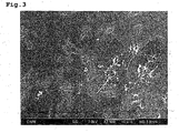
- the carbon fibrous structure to be used in a composite material according to the present invention is, as shown in SEM photo of Fig. 3 or TEM photos of Fig. 4A and 4B , composed of carbon fibers each having an outside diameter of 15 - 100 nm, and a granular part at which the carbon fibers are bound in a state so that said carbon fibers are externally elongated from the granular part.
- the reason for restricting the outside diameter of the carbon fibers to a range of 15 nm to 100 nm is because when the outside diameter is less than 15 nm, the cross-sections of the carbon fibers do not have polygonal figures as described later. According to physical properties, the smaller the diameter of a fiber, the greater the number of carbon fibers will be for the same weight and/or the longer the length in the axial direction of the carbon fiber. This property would be followed by an enhanced electric conductivity. Thus, carbon fibrous structures having an outside diameter exceeding 100 nm are not preferred for use as modifiers or additives for a matrix such as a resin, etc. Particularly, it is more desirable for the outside diameter of the carbon fibers to be in the range of 20 - 70 nm.
- Annealing at a temperature of not less than 2400 °C causes the carbon fibers to have polygonal cross-sections. Additionally, annealing lessens the spacing between the layered graphene sheets and increases the true density of the carbon fiber from 1.89 g/cm 3 to 2.1 g/cm 3 . As a result, the carbon fibers become denser and have fewer defects in both the stacking direction and the surface direction of the graphene sheets that make up the carbon fiber, and their flexural rigidity (EI) and dispersibility in a resin can also be enhanced and improved.
- EI flexural rigidity
- the outside diameter of a fine carbon fiber undergoes a change along the axial direction of the fiber.
- the outside diameter of the carbon fiber is not constant, but changes along the length of the fiber, it would be expected that some anchor effect may be provided to the carbon fiber at the.. interface with the matrix material, and thus migration of the carbon fibrous structure in the matrix can be restrained, leading to improved dispersion stability.
- fine carbon fibers having a predetermined outside diameter configures the three dimensional network and are bound together by a granular part produced in a growth process of the carbon fibers so that the carbon fibers are externally elongated from the granular part.
- the carbon fibers Since multiple fine carbon fibers are not only entangled with each other, but fused together at the granular part , the carbon fibers will not disperse as single fibers, but will be dispersed as bulky carbon fibrous structures when added to a matrix such as a resin. Since the fine carbon fibers are bound together by a granular part produced in the growth process of the carbon fibers in a carbon fibrous structure according to the present invention, the carbon fibrous structure itself can enjoy superior properties such as electric property.
- carbon fibrous structures according to the present invention when measuring electrical resistance under a certain pressed density, have an extremely low resistivity, as compared with that of a simple aggregate of the fine carbon fibers and that of the carbon fibrous structures in which the fine carbon fibers are fixed at contacting points with a carbonaceous material or carbonized substance therefrom after the synthesis of the carbon fibers.
- carbon fibrous structures when carbon fibrous structures are added and distributed in a matrix, they can form good conductive paths within the matrix.
- the granular part is produced in the growth process of the carbon fibers as mentioned above, the carbon - carbon bonds in the granular part are well developed. Further, the granular part appears to include mixed state of sp2- and sp3-bonds, although it is not clear accurately.
- the granular part and the fibrous parts are continuous mutually by virtue of a structure comprising patch-like sheets of carbon atoms laminated together. Further, after the high temperature treatment, at least a part of graphene layers constituting the granular part is continued on graphene layers constituting the fine carbon fibers elongated externally from the granular part, as shown in Figs.
- the condition of being "extended outwardly" from the granular part used herein means principally that the carbon fibers and granular part are linked together by carbon crystalline structural bonds as mentioned above, but does not means that they are apparently combined together by any additional binding agent (involving carbonaceous ones).
- the granular part has at least one catalyst particle or void therein, the void being formed due to the volatilization and elimination of the catalyst particle during the heating process after the generation process.
- the void (or catalyst particle) is essentially independent from hollow parts which are formed in individual fine carbon fibers which are extended outwardly from the granular part (although, a few voids which happened to be associate with the hollow part may be observed) .
- the number of the catalyst particles or voids is not particularly limited, it may be about 1 - 1000 a granular particle, more preferably, about 3 - 500 a granular particle.
- the granular part formed can have a desirable size as mentioned later.
- the per-unit size of the catalyst particle or void existing in the granular particle may be, for example, 1 - 100 nm, preferably, 2 - 40 nm, and more preferably, 3 - 15 nm.
- the diameter of the granular part is larger than the outside diameter of the carbon fibers as shown in Fig. 2 .
- the diameter of granular part is 1.3 - 250 times larger than the outside diameter of the carbon fibers, preferably 1.5 - 100 times, and more preferably, 2.0-25 times larger, on average.
- the carbon fibers that are externally elongated from the granular part have stronger binding force, and thus, even when the carbon fibrous structures are exposed to a relatively high shear stress during combining with a matrix such as resin, they can be dispersed as maintaining its three-dimensional carbon fibrous structures into the matrix.
- the granular part has an extremely larger particle diameter, that is, exceeding 250 times of the outer diameter of the carbon fibers, the undesirable possibility that the fibrous characteristics of the carbon fibrous structure are lost will arise.
- the carbon fibrous structure will be not suitable for an additive or compounding agent to a various matrix, and thus it is not desirable.
- the "particle diameter of the granular part" used herein is the value which is measured by assuming that the granular part, which is the binding site for the mutual carbon fibers, is one spherical particle.
- the concrete value for the particle diameter of the granular part will be depended on the size of the carbon fibrous structure and the outer diameter of the fine carbon fiber in the carbon fibrous structure, for example, it may be 20 - 5000 nm, more preferably, 25 - 2000 nm, and most preferably, 30 - 500 nm, on average.
- the granular part may be roughly globular in shape because the part is produced in the growth process of the carbon fibers as mentioned above.
- the degree of roundness thereof may lay in the range of from 0.2 to ⁇ 1, preferably, 0.5 to 0.99, and more preferably, 0.7 to 0.98.
- the binding of the carbon fibers at the granular part is very tight as compared with, for example, that in the structure in which mutual contacting points among the carbon fibers are fixed with carbonaceous material or carbonized substance therefrom. It is also because the granular part is produced in the growth process of the carbon fibers as mentioned above. Even under such a condition as to bring about breakages in the carbon fibers of the carbon fibrous structure, the granular part (the binding site) is maintained stably.
- the changing rate in the mean diameter of the granular parts is not more than 10%, preferably, not more than 5%, thus, the granular parts, i.e., the binding sites of fibers are maintained stably.
- the carbon fibrous structure has an area-based circle-equivalent mean diameter of 50 - 100 ⁇ m, and more 'preferably', 60 - 90 ⁇ m.
- the "area-based circle-equivalent mean diameter" used herein is the value which is determined by taking a picture for the outside shapes of the carbon fibrous structures with a suitable electron microscope, etc., tracing the contours of the respective carbon fibrous structures in the obtained picture using a suitable image analysis software, e.g., WinRoof TM (Mitani Corp.), and measuring the area within each individual contour, calculating the circle-equivalent mean diameter of each individual carbon fibrous structure, and then, averaging the calculated data.
- the circle-equivalent mean diameter may be affected by the kind of matrix material, e.g. a resin, to be complexed
- the circle-equivalent mean diameter may become a factor by which the maximum length of a carbon fibrous structure upon combining into a matrix such as a resin is determined.
- the circle-equivalent mean diameter is not more than 50 ⁇ m, the electrical conductivity of the obtained composite may not be expected to reach a sufficient level, while when it exceeds 100 ⁇ m, an undesirable increase in viscosity may be expected to happen upon kneading of the carbon fibrous structures in the matrix. The increase in viscosity may be followed by failure of dispersion or may result in an inferior moldability.
- the carbon fibrous structure according to the present invention has the configuration where the fine carbon fibers existing in three dimensional network state are bound together by the granular part(s) so that the carbon fibers are externally elongated from the granular part (s).
- the mean distance between adjacent granular parts may be, for example, 0.5 - 300 ⁇ m, preferably, 0.5 - 100 ⁇ m, and more preferably, 1 - 50 ⁇ m.
- the distance between adjacent granular parts used herein is determined by measuring distance from the center of a granular part to the center of another granular part which is adjacent the former granular part.
- the mean distance between the granular parts is not more than 0.5 ⁇ m, a configuration where the carbon fibers form an inadequately developed three dimensional network may be obtained. Therefore, it may become difficult to form good electrically conductive paths when the carbon fiber structures each having such an inadequately developed three dimensional network are added and dispersed to a matrix such as a resin.
- the mean distance exceeds 300 ⁇ m, an undesirable increase in viscosity may be expected to happen upon adding and dispersing the carbon fibrous structures in the matrix. The increase in viscosity may result in an inferior dispersibility.
- the carbon fibrous structure used in the present invention may exhibit a bulky, loose form in which the carbon fibers are sparsely dispersed, because the carbon fibrous structure is comprised of carbon fibers that are configured as a three dimensional network and are bound together by a granular part so that the carbon fibers are externally elongated from the granular part as mentioned above. It is desirable that the bulk density thereof is in the range of 0.0001 - 0.05 g/cm 3 , more preferably, 0.001 - 0.02 g/cm 3 . When the bulk density exceeds 0.05 g/cm 3 , the improvement of the physical properties in a matrix such as a resin would become difficult with a small dosage.
- the carbon fibrous structure according to the present invention can enjoy good electric properties in itself, since the carbon fibers in the structure are bound together by a granular part produced in the growth process of the carbon fibers as mentioned above.
- the carbon fibrous structure has a powder electric resistance determined under a certain pressed density 0.8 g/cm 3 , of not more than 0.02 Q ⁇ cm, more preferably, 0.001 to 0.10 Q ⁇ cm. If the particle's resistance exceeds 0.02 ⁇ cm, it may become difficult to form good electrically conductive paths when the structure is added to a matrix such as a resin.
- the graphene sheets that make up the carbon fibers have a small number of defects, and more specifically, for example, the I D /I G ratio of the carbon fiber determined by Raman spectroscopy is not more than 0.2, more preferably, not more than 0 . 1.
- the peak (G band) at 1580 cm -1 appears.
- the carbon fibrous structure according to the present invention has a combustion initiation temperature in air of not less than 750 °C, preferably, 800 °C - 900 °C.
- a combustion initiation temperature in air of not less than 750 °C, preferably, 800 °C - 900 °C.
- a carbon fibrous structure having the above described, desirable configuration may be prepared as follows, although it is not limited thereto.
- an organic compound such as a hydrocarbon is chemical thermally decomposed through the CVD process in the presence of ultrafine particles of a transition metal as a catalyst in order to obtain a fibrous structure (hereinafter referred to as an "intermediate"), and then the intermediate thus obtained undergoes a high temperature heating treatment.
- hydrocarbons such as benzene, toluene, xylene; carbon monoxide (CO); and alcohols such as ethanol may be used. It is preferable, but not limited, to use as carbon sources at least two carbon compounds which have different decomposition temperatures.
- the words "at least two carbon compounds" used herein not only include two or more kinds of raw materials, but also include one kind of raw material that can undergo a reaction, such as hydrodealkylation of toluene or xylene, during the course of synthesis of the fibrous structure such that in the subsequent thermal decomposition procedure it can function as at least two kinds of carbon compounds having different decomposition temperatures.
- the decomposition temperatures of individual carbon compounds may be varied not only by the kinds of the carbon compounds, but also by the gas partial pressures of individual carbon compounds, or molar ratio between the compounds. Therefore, as the carbon compounds, a relatively large number of combinations can be used by adjusting the composition ratio of two or more carbon compounds in the raw gas.
- the carbon fibrous structure according to the present invention can be prepared by using two or more carbon compounds in combination, while adjusting the gas partial pressures of the carbon compounds so that each compound performs mutually different decomposition temperature within a selected thermal decomposition reaction temperature range, and/or adjusting the residence time for the carbon compounds in the selected temperature region, wherein the carbon compounds to be selected are selected from the group consisting of alkanes for cycloalkanes such as methane, ethane, propanes, butanes, pentanes, hexanes, cyclopropane, cycrohexane, particularly, alkanes having 1 -7 carbon atoms; alkenes or cycloolefin such as ethylene, propylene, butylenes, pentenes, heptenes, cyclopentene, particularly, alkenes having 1 - 7 carbon atoms; alkynes such as acetylene, propyne, particularly, alkynes having 1 - 7
- the molar ratio of methane/benzene is >1 - 600, preferably, 1.1 - 200, and more preferably 3 -100.
- the ratio is for the gas composition ratio at the inlet of the reaction furnace. For instance, when as one of carbon sources toluene is used, in consideration of the matter that 100% of the toluene decomposes into methane and benzene in proportions of 1: 1 in the reaction furnace, only a deficiency of methane may be supplied separately.
- methane / benzene molar ratio 3 mol methane may be added to 1 mol toluene.
- methane to be added to the toluene it is possible to use the methane which is contained as an unreacted form in the exhaust gas discharged from the reaction furnace, as well as a fresh methane specially supplied.
- composition ratio within such a range, it is possible to obtain the carbon fibrous structure in which both the carbon fiber parts and granular parts are efficiently developed.
- Inert gases such as argon, helium, xenon; and hydrogen may be used as an atmosphere gas.
- a mixture of transition metal such as iron, cobalt, molybdenum, or transition metal compounds such as ferrocene, metal acetate; and sulfur or a sulfur compound such as thiophene, ferric sulfide; may be used as a catalyst.
- the intermediate may be synthesized using a CVD process with hydrocarbon or etc. , which has been conventionally used in the art.
- the steps may comprise gasifying a mixture of hydrocarbon and a catalyst as a raw material, supplying the gasified mixture into a reaction furnace along with a carrier gas such as hydrogen gas, etc., and undergoing thermal decomposition at a temperature in the range of 800 °C - 1300 °C.
- the product obtained is an aggregate, which is of several to several tens of centimeters in size and which is composed of plural carbon fibrous structures (intermediates), each of which has a three dimensional configuration where fibers having 15 - 100 nm in outside diameter are bound together by a granular part that has grown around the catalyst particle as the nucleus.
- aggregate which is of several to several tens of centimeters in size and which is composed of plural carbon fibrous structures (intermediates), each of which has a three dimensional configuration where fibers having 15 - 100 nm in outside diameter are bound together by a granular part that has grown around the catalyst particle as the nucleus.
- the thermal decomposition reaction of the hydrocarbon raw material mainly occurs on the surface of the catalyst particles or on growing surface of granular parts that have grown around the catalyst particles as the nucleus, and the fibrous growth of carbon may be achieved when the recrystallization of the carbons generated by the decomposition progresses in a constant direction.
- the balance between the thermal decomposition rate and the carbon fiber growth rate is intentionally varied. Namely, for instance, as mentioned above, to use as carbon sources at least two kinds of carbon compounds having different decomposition temperatures may allow the carbonaceous material to grow three dimensionally around the granular part as a centre, rather than in one dimensional direction.
- the three dimensional growth of the carbon fibers depends not only on the balance between the thermal decomposition rate and the growing rate, but also on the selectivity of the crystal face of the catalyst particle, residence time in the reaction furnace, temperature distribution in the furnace, etc.
- the balance between the decomposition rate and the growing rate is affected not only by the kinds of carbon sources mentioned above, but also by reaction temperatures, and gas temperatures, etc.
- the growing rate is faster than the decomposition rate, the carbon material tends to grow into fibers
- the thermal decomposition rate is faster than the growing rate, the carbon material tends to grow in peripheral directions of the catalyst particle.
- the raw material gas supplied into the reaction furnace from a supply port is forced to form a turbulent flow in proximity to the supply port.
- turbulent flow used herein means a furiously irregular flow, such as flow with vortexes.
- metal catalyst fine particles are produced by the decomposition of the transition metal compound as the catalyst involved in the raw material gas.
- the production of the fine particles is carried out through the following steps. Namely, at first, the transition metal compound is decomposed to make metal atoms, then, plural number of, for example, about one hundred of metal atoms come into collisions with each other to create a cluster. At the created cluster state, it can not function as a catalyst for the fine carbon fiber. Then, the clusters further are aggregated by collisions with each other to grow into a metal crystalline particle of about 3 - 10 nm in size, and which particle comes into use as the metal catalyst fine particle for producing the fine carbon fiber.
- the collisions of carbon atoms or collisions of clusters become more vigorously as compared with the collisions only due to the Brownian movement of atoms or collisions, and thus the collision frequency per unit time is enhanced so that the metal catalyst fine particles are produced within a shorter time and with higher efficiency. Further, Since concentration, temperature, and etc. are homogenized by the force of vortex flow, the obtained metal catalyst fine particles become uniform in size. Additionally, during the process of producing metal catalyst fine particles, a metal catalyst particles' aggregate in which numerous metal crystalline particles was aggregated by vigorous collisions with the force of vortex flows can be also formed.
- the metal catalyst particles are rapidly produced as mentioned above, the decomposition of carbon compound can be accelerated so that an ample amount of carbonaceous material can be provided.
- the fine carbon fibers grow up in a radial pattern by taking individual metal catalyst particles in the aggregate as nuclei.
- the carbon material may also grow in the circumferential direction so as to form the granular part around the aggregate, and thus the carbon fiber structure of the desired three dimensional configuration may be obtained with efficiency.
- the concrete means for creating the turbulence to the raw material gas flow near the supply port for the raw material gas is not particularly limited.
- it is adaptable to provide some type of collision member at a position where the raw material gas flow introduced from the supply port can be interfered by the collision section.
- the shape of the collision section is not particularly limited, as far as an adequate turbulent flow can be formed in the reaction furnace by the vortex flow which is created at the collision section as the starting point.
- embodiments where various shapes of baffles, paddles, tapered tubes, umbrella shaped elements, and etc., are used singly or in varying combinations and located at one or more positions may be adaptable.
- the intermediate obtained by heating the mixture of the catalyst and hydrocarbon at a constant temperature in the range of 800 °C - 1300°C, has a structure that resembles sheets of carbon atoms laminated together, (and being still in half-raw, or incomplete condition).
- the D band of the intermediate is very large and many defects are observed.
- the obtained intermediate is associated with unreacted raw materials, nonfibrous carbon, tar moiety, and catalyst metal.
- the intermediate is subjected to a high temperature heat treatment using a proper method at a temperature of 2400 - 3000 °C in order to remove such residues from the intermediate and to produce the intended carbon fibrous structure with few defects.
- the intermediate may be heated at 800 - 1200 °C to remove the unreacted raw material and volatile flux such as the tar moiety, and thereafter annealed at a high temperature of 2400 - 3000 °C to produce the intended structure and, concurrently, to vaporize the catalyst metal, which is included in the fibers, to remove it from the fibers.
- a reducing gas and carbon monoxide into the inert gas atmosphere to protect the carbon structures.
- the patch-like sheets of carbon atoms are rearranged to associate mutually and then form multiple graphene sheet-like layers.
- the aggregates may be subjected to crushing in order to obtain carbon fibrous structures, each having an area-based circle-equivalent mean diameter of several centimeters. Then, the obtained carbon fibrous structures may be subjected to pulverization in order to obtain the carbon fibrous structures having an area-based circle-equivalent mean diameter of 50 - 100 ⁇ m. It is also possible to perform the pulverization directly without crushing.
- the initial aggregates involving plural carbon fibrous structures according to the present invention may also be granulated for adjusting shape, size, or bulk density to one' s suitable for using a particular application.
- the annealing would be performed in a state such that the bulk density is low (the state that the fibers are extended as much as they can and the voidage is sufficiently large). Such a state may contribute to improved electric conductivity of a resin matrix.
- the carbon fibrous structures used in the present invention may have the following properties:
- organic polymer inorganic material, metal and so on can all be used, but organic polymers are preferred.
- organic polymers may include various thermoplastic resins such as polypropylene, polyethylene, polystyrene, polyvinyl chloride, polyacetal, polyethylene terephthalate, polycarbonate, polyvinyl acetate, polyamide, polyamide imide, polyether imide, polyether ether ketone, polyvinyl alcohol, poly phenylene ether, poly (meth) acrylate, and liquid crystal polymer; and various thermosetting resins such as epoxy resin, vinyl ester resin, phenol resin, unsaturated polyester resin, furan resins, imide resin, urethane resin, melamine resin, silicone resin and urea resin; as well as various elastomers such as natural rubber, styrene butadiene rubber (SBR), butadiene rubber (BR), polyisoprene rubber (IR), ethylene-propylene rubber (EPDM), nitrile rubber (NBR), polychloroprene rubber (CR), isobutylene isoprene rubber (SBR
- organic polymers may be in various forms of composition, such as adhesive, fibers, paint, ink, and etc.
- the matrix may be an adhesive agent such as epoxy type adhesive, acrylic type adhesive, urethane type adhesive, phenol type adhesive, polyester type adhesive, polyvinyl chloride type adhesive, urea type adhesive, melamine type adhesive, olefin type adhesive, acetic acid vinyl type adhesive, hotmelt type adhesive, cyano acrylate type adhesive, rubber type adhesive, cellulose type adhesive, etc.; fibers such as acrylic fibers, acetate fibers, aramid fiber, nylon fibers, novoloid fibers, cellulose fibers, viscose rayon fibers, vinylidene fibers, vinylon fibers, fluorine fibers, polyacetal fibers, polyurethane fibers, polyester fibers, polyethylene fibers, polyvinyl chloride fibers, polypropylene fibers, etc.; or a paint such as phenol resin type, alkyd type, epoxy type, acrylic resin type, unsaturated polyester type, polyurethane type, silicon type, fluorine resin type, synthetic resin emulsion type
- Inorganic materials include ceramic materials and inorganic oxide polymers.
- Preferred concrete examples may include carbon materials such as carbon-carbon composite, glass, glass fiber, flat glass and other forming glass, silicate ceramics and other heat resisting ceramics, e.g. aluminum oxide, silicon carbide, magnesium oxide, silicone nitride and boron nitride.
- the matrix is metal, aluminum, magnesium, lead, copper, tungsten, titanium, niobium, hafnium, vanadium, alloys, and mixtures thereof, are exemplified as preferable metals.
- filling agents in addition to the above mentioned carbon fibrous structures.
- Such filling agents may include metallic minute particles, silica, calcium carbonate, magnesium carbonate, carbon black, glass fibers, and carbon fibers. These filling agents may be used singly or in any combination of more than two agents.
- a composite material according to the present invention includes the aforementioned carbon fibrous structures at an effective amount in the matrix as mentioned above.
- the amount depends on the intended usage of the composite material and the kind of matrix to be used, it is generally in the range of about 0.1 to about 30% by weight of total weight of the composite material.
- the reinforcement may be less effective and benefits such as mechanical strength and electric conductivity would be more difficult to attain.
- the proportion is more than 30% by weight, mechanical strength of the composite may decline and adhesive property of the matrix material, such as the paint, the adhesive, etc., may become worse.
- fine carbon fibers of the carbon fibrous structures can distribute themselves uniformly throughout the matrix even when the carbon fibrous structures are added at a relative small amount.
- composite materials useful as functional materials having good electrical conductivity, electromagnetic wave shielding ability, heat conductivity, etc., or as structural materials having high strength, or the like can be obtained.
- the carbon fibrous structures may be mixed with a resin to produce a conductive resin or conductive resin molded body, which may be used as wrapping material, gasket, container, resistance body, conductive fiber, electrical wire, adhesive, ink, paint, and etc.
- a resin to produce a conductive resin or conductive resin molded body, which may be used as wrapping material, gasket, container, resistance body, conductive fiber, electrical wire, adhesive, ink, paint, and etc.
- similar effects can be expected with a composite material that results from adding the carbon fibrous structures to an inorganic material, such as ceramic, metal, etc.
- the carbon fibrous structures may be added to fuel as well as a matrix material similar to the above-described applications based on electrical conductivity.
- the carbon fibrous structures may be mixed with a resin and used as electromagnetic wave shielding materials, in the form of paints or other molded shapes.
- the carbon fibrous structures may be mixed with a matrix, such as a resin or metal, to improve slidability of the matrix.
- a matrix such as a resin or metal
- Such materials may be used in, for example, rollers, brake parts, tires, bearings, lubricating oil, cogwheel, pantograph, etc.
- the carbon fibrous structures can also be used in wires, bodies of consumer electronics or cars or airplanes, housings of machines, etc. Additionally, it is possible to use these carbon fibrous structures as substitutes for conventional carbon fibers or beads, and they may be used in a terminal or poles of a battery, switch, vibration damper, etc.
- the carbon fibers in the carbon fibrous structures have excellent strength, and moderate flexibility and elasticity. Thus, they may be advantageously used as fillers in various materials, for example, to form a network structure. Based on these characteristics, it is possible to use these carbon fibrous structures, for example, to strengthen the terminals of power devices such as a lithium ion rechargeable battery or a lead-acid battery, a capacitor, and a fuel cell, and to improve cycle characteristics of these power devices.
- power devices such as a lithium ion rechargeable battery or a lead-acid battery, a capacitor, and a fuel cell
- the Raman spectroscopic analysis was performed with LabRam 800 manufactured by HORIBA JOBIN YVON, S.A.S., using 514 nm argon laser.
- Combustion behavior was determined using TG-DTA manufactured by MAX SCIENCE CO. LTD., at air flow rate of 0.1 liter/minute and heating rate of 10 °C/minute.
- TG indicates a quantity reduction
- DTA indicates an exothermic peak.
- the top position of the exothermic peak was defined as the combustion initiation temperature.
- the outer diameter of the fine carbon fibers in the individual carbon fibrous structures to be measured are determined, and then, from the outer diameter determined and the circle-equivalent mean diameter of the granular part calculated as above, the ratio of circle-equivalent mean diameter to the outer diameter of the fine carbon fiber is calculated for each individual carbon fibrous structure, and then the data obtained are averaged.
- the carbon fiber structure is added at a ratio of 30 ⁇ l/ml in order to prepare the dispersion liquid sample of the carbon fibrous structure.
- the mean diameter D 50 of the granular part is compared with the initial average diameter of the granular parts in order to obtain the rate of variability (%) thereof.
- a test piece was cut up into 10 mm wide strips, and then transverse rupture strength (kg/mm 2 ) of the resultant strips was determined by a tension test machine.
- test piece was cut out into a proper shape, and then analyzed by the laser flashmethod for its thermal conductivity (W/m ⁇ K).
- carbon fibrous structures were synthesized using toluene as the raw material.
- the synthesis was carried out in the presence of a mixture of ferrocene and thiophene as the catalyst, and under the reducing atmosphere of hydrogen gas.
- Toluene and the catalyst were heated to 380 °C along with the hydrogen gas, and then they were supplied to the generation furnace, and underwent thermal decomposition at 1250 °C in order to obtain the carbon fibrous structures (first intermediate).
- the generation furnace used for the carbon fibrous structures is illustrated schematically in Fig. 9 .
- the generation furnace 1 was equipped at the upper part thereof with a inlet nozzle 2 for introducing the raw material mixture gas comprising toluene, catalyst and hydrogen gas as aforementioned into the generation furnace 1.
- a cylindrical-shaped collision member 3 was provided at the outside of the inlet nozzle 2. The collision member 3 was set to be able to interfere in the raw material gas flow introduced from the raw material supply port 4 located at the lower end of the inlet nozzle 2.
- the raw material gas supplying rate to the generation furnace was 1850 NL/min., and the pressure was 1.03 atms.
- the synthesized first intermediate was baked at 900 °C in nitrogen gas in order to remove hydrocarbons such as tar and to obtain a second intermediate.
- the R value of the second intermediate measured by the Raman spectroscopic analysis was found to be 0.98.
- Sample for electron microscopes was prepared by dispersing the first intermediate into toluene. Figs 1 and 2 show SEM photo and TEM photo of the sample, respectively.
- the second intermediate underwent a high temperature heat treatment at 2600 °C.
- the obtained aggregates of the carbon fibrous structures underwent pulverization using an air flow pulverizer in order to produce the carbon fibrous structures to be used in the present invention.
- a sample for electron microscopes was prepared by dispersing ultrasonically the obtained carbon fibrous structures into toluene.
- Figs 3 , and 4 show SEM photo and TEM photos of the sample, respectively.
- Fig. 5 shows SEM photo of the obtained carbon fibrous structures as mounted on a sample holder for electron microscope, and Table 1 shows the particle distribution of obtained carbon fibrous structures.
- the carbon fibrous structures had an area based circle-equivalent mean diameter of 72.8 ⁇ m, bulk density of 0.0032 g/cm 3 , Raman I D /I G ratio of 0.090, TG combustion temperature of 786 °C, spacing of 3.383 A, powder electric resistance of 0.0083 ⁇ cm, and density after decompression of 0.25 g/cm 3 .
- the mean diameter of the granular parts in the carbon fibrous structures was determined as 443 nm (SD 207 nm), that is 7.38 times larger than the outer diameter of the carbon fibers in the carbon fibrous structure.
- the mean roundness of the granular parts was 0.67 (SD 0.14).
- Table 2 provides a summary of the various physical properties as determined in Synthetic Example 1.
- carbon fibrous structures were synthesized using a part of the exhaust gas from the generation furnace as a recycling gas in order to use as the carbon source the carbon compounds such as methane, etc., included in the recycling gas, as well as a fresh toluene.
- the synthesis was carried out in the presence of a mixture of ferrocene and thiophene as the catalyst, and under the reducing atmosphere of hydrogen gas.
- Toluene and the catalyst as a fresh raw material were heated to 380 °C along with the hydrogen gas in a preheat furnace, while a part of the exhaust gas taken out from the lower end of the generation furnace was used as a recycling gas. After it was adjusted to 380 °C, it was mixed with the fresh raw material gas on the way of the supplying line for the fresh raw material to the generation furnace. The mixed gas was then supplied to the generation furnace.
- composition ratio in the recycling gas used were found to be CH 4 7.5%, C 6 H 6 0.3%, C 2 H 2 0.7%, C 2 H 6 0.1%, CO 0. 3%, N 2 3.5%, and H 2 87.6% by the volume based molar ratio.
- Example 1 Then they were underwent thermal decomposition at 1250 °C in order to obtain the carbon fibrous structures (first intermediate) in an analogous fashion as Example 1.
- the constitution of the generation furnace used for the carbon fibrous structures (first intermediate) was the same as that illustrated in Fig. 9 , except that the cylindrical-shaped collision member 3 was omitted.
- the raw material gas supplying rate to the generation furnace was 1850 NL/min., and the pressure was 1.03 atms as in the case of Example 1.
- the synthesized first intermediate was baked at 900 °C in nitrogen gas in order to remove hydrocarbons such as tar and to obtain a second intermediate.
- the R value of the second intermediate measured by the Raman spectroscopic analysis was found to be 0.83.
- Sample for electron microscopes was prepared by dispersing the first intermediate into toluene. SEM photo and TEM photo obtained for the sample are in much the same with those of Example 1 shown in Figs 1 and 2 , respectively.
- the second intermediate underwent a high temperature heat treatment at 2600 °C.
- the obtained aggregates of the carbon fibrous structures underwent pulverization using an air flow pulverizer in order to produce the carbon fibrous structures according to the present invention.
- a sample for electron microscopes was prepared by dispersing ultrasonically the obtained carbon fibrous structures into toluene. SEM photo and TEM photo obtained for the sample are in much the same with those of Example 1 shown in Figs 3 and 4 , respectively.
- the carbon fibrous structures had an area based circle-equivalent mean diameter of 75.8 ⁇ m, bulk density of 0.005 g/cm 3 , Raman I D /I G ratio of 0.086, TG combustion temperature of 807 °C, spacing of 3.386 A, powder electric resistance of 0.0077 ⁇ cm, and density after decompression of 0.26 g/cm 3 .
- the mean diameter of the granular parts in the carbon fibrous structures was determined as 349.5 nm (SD 180. 1 nm), that is 5.8 times larger than the outer diameter of the carbon fibers in the carbon fibrous structure.
- the mean roundness of the granular parts was 0.69 (SD 0.15).
- Table 3 provides a summary of the various physical properties as determined in Example 2.
- Epoxy type adhesive compositions were prepared according to the formulations shown in Table 5, by blending the carbon fibrous structures obtained in Synthetic Example 1, with an epoxy resin (ADEKA RESIN TM , manufactured by Asahi DenkaCo., Ltd.) andahardener (ADEKAHARDENER TM , manufactured by Asahi Denka Co., Ltd.), followed by kneading them with a rotation - revolution type centrifugal mixer (Awatori-NERITARO, manufactured by Thinky Co., Ltd.) for ten minutes.
- an epoxy resin (ADEKA RESIN TM , manufactured by Asahi DenkaCo., Ltd.) andahardener (ADEKAHARDENER TM , manufactured by Asahi Denka Co., Ltd.)
- ADEKAHARDENER TM manufactured by Asahi Denka Co., Ltd.
- the epoxy type adhesive compositions thus obtained were applied on a glass plate, using an applicator having a coating width of 100 mm and a gap of 200 ⁇ m.
- the coated film was then hardened at 170 °C for 30 minutes to obtain a hardened film.
- the hardened film was then cut up into 50 mm x 50 mm test pieces. Using these test pieces, volume resistivity and thermal conductivity were determined. The results obtained are shown in Table 5.
- a similar epoxy resin composite film was prepared in a similar manner, except that the content of the carbon fibrous structures was set to be 0.5% by weight.
- the optical micrograph of the film is shown in Fig. 8 . It is apparent from Fig. 8 that the carbon fibrous structures have a good dispersibility in the resin matrix.
- Epoxy type adhesive compositions were prepared according to the formulations shown in Table 6, by blending carbon black (#3350B, manufactured by Mitsubishi Chemical) with an epoxy resin (ADEKA RESIN TM , epoxy equivalent 190, manufactured by Asahi Denka Co., Ltd.) and a hardener (ADEKA HARDENER TM , manufactured by Asahi Denka Co., Ltd.), followed by kneading them with a rotation - revolution type centrifugal mixer (Awatori-NERITARO, manufactured by Thinky Co., Ltd.) for ten minutes.
- the epoxy type adhesive compositions thus obtained were evaluated in the same manners as in Example 1. The results are shown in Table 6.
- Resin pellets were prepared according to the formulations shown in Table 7, by blending the carbon fibrous structures obtained in Synthetic Example 1 with a polycarbonate resin (Panlite ® L-1225L, manufactured by Teijin Chemicals Ltd.) or a polyamide resin (Leona TM 1300S, manufactured by Asahi Kasei Corporation), followed by melt-kneading them with a twin screw vented extruder (TEM35, manufactured by Toshiba Machine Co., Ltd.). The pellets thus obtained were dried at 120°C for ten hours, and then used in injection molding, under a prescribed condition, to produce test peaces. Using the test pieces, the volume resistivity and thermal conductivity were determined. The results obtained are shown in Table 7.
- Resin pellets were prepared according to the formulations shown in Table 8, by blending carbon black (#33508, manufactured by Mitsubishi Chemical) with a polycarbonate resin (Panlite ® L-1225L, manufactured by Teijin Chemicals Ltd.) or a polyamide resin (Leona TM 1300S, manufactured by Asahi Kasei Corporation), followed bymelt-kneading them with a twin screw vented extruder (TEM35, manufactured by Toshiba Machine Co., Ltd.). The pellets thus obtained were dried at 120°C for ten hours, and then used in injection molding, under a prescribed condition, to obtain test pieces. Using these test pieces, the volume resistivity and thermal conductivity were determined. The results obtained are shown in Table 8.
- Example 8 9 10 11 12 13 Polycarbonate 100 100 100 Polyamide 66 100 100 100 Carbon fibrous structure 5 10 20 5 10 20 Volume resistivity ( ⁇ cm) 3.7 x 10 3 8. 6 x 10 1 9.1 x 10 1 8. 9 x 10 3 2.3 x 10 2 10 1 Thermal conductivity (W/m ⁇ K) 1.2 2.2 3.1 1.1 2.1 2.9
- Sheet-shaped test pieces were prepared according to the formulations shown in Table 7, by blending the carbon fibrous structures obtained in Synthetic Example 1 with SBR (Tufdene TM 2003, styrene content of 25% by weight, manufactured by Asahi Kasei Corporation) or NBR(DN401LL, acrylonitrile content of 15% by weight, manufactured by Zeon Corporation), followed by kneading them with a Banbury mixer and rolls, and then vulcanizing the resultant mixture with a press at 150°C for 20 minutes. Using these test pieces, the volume resistivity was determined. The results obtained are shown in Table 9.
- Sheet-shaped test pieces were prepared according to the formulations shown in Table 8, by blending carbon black (#3350B, manufactured by Mitsubishi Chemical) with SBR (Tufdene TM 2003, styrene content of 25% by weight, manufactured by Asahi Kasei Corporation) or NBR (DN401LL, acrylonitrile content of 15% by weight, manufactured by Zeon Corporation), followed by kneading them with a Banbury mixer and rolls, and then vulcanizing the resultant mixture with a press at 150 °C for 20 minutes. Using these test pieces, the volume resistivity was determined. The results obtained are shown in Table 10.
- Zinc oxide zinc white #1, manufactured by Sakai Chemical Industry Co., Ltd. Sulfur: #300, manufactured by Tsurumi Chemical Industrial Co. , Ltd. Vulcanizing accelerator DM: manufactured by Ouchishinko Chemical Industrial Co., Ltd. Accelerator TET: manufactured by Ouchishinko Chemical Industrial Co., Ltd.
- the carbon fibrous structures obtained in Synthetic Example 1 were blended, according to the prescriptions shown in Table 9, with aluminum nitride powder having an average grain size of 1.5 ⁇ m; yttrium oxide, having an average grain size of 0.3 ⁇ m, 2.0 parts by weight; and vanadium trioxide, 0.1 parts by weight (reduced to vanadium element). Then, to the resultant mixture, 100 parts by weight of a binder, which comprises a dispersant, 2 parts by weight; polyvinyl butyral, 10 parts by weight; dibutyl phthalate as a plasticizer, 5 parts by weight; toluene, was added to prepare a slurry. Next, this slurry was used to form a green sheet using a doctor blade method.
- a binder which comprises a dispersant, 2 parts by weight; polyvinyl butyral, 10 parts by weight; dibutyl phthalate as a plasticizer, 5 parts by weight; toluene
- the green sheet was die-cut to a prescribed shape in order to obtain a plate-shaped molded article.
- the plate was heated at 440 °C for three hours in air to remove the binder. After that, the plate was put into a container made of boron nitride and the container was sealed. Then, the plate was sintered in a nitrogen atmosphere by ramping the temperatures from 1700 °C to 1950 °C over 3 hours, and thereafter maintaining the temperature at 1950 °C for another 3 hours in order to obtain a test piece 60 mm x 60 mm square and 0.35 mm thick. Using the test piece, the thermal conductivity and transverse rupture strength were determined. The results are shown in Table 11.
- Control samples were prepared in a similar manner as the above Examples.
- aluminum nitride powder having an average grain size of 1.5 ⁇ m; yttrium oxide having an average grain size of 0.3 ⁇ m, 2.0 parts by weight; vanadium trioxide, 0.1 parts by weight (reduced to vanadium element) ; and carbon black (#3350B, manufactured by Mitsubishi Chemical) were blended according to the formulations shown in Table 10.
- a binder which comprises a dispersant, 2 parts by weight; polyvinyl butyral, 10 parts by weight; dibutyl phthalate as a plasticizer, 5 parts by weight; toluene, was added to prepare a slurry.
- this slurry was used to form a green sheet using a doctor blade method, and the green sheet was die-cut to a prescribed shape in order to obtain plate-shaped molded article.
- the plate was heated at 440°C for three hours in air to remove the binder. After that, the plate was put in a container made of boron nitride and the container was sealed. Then, the plate was sintered in a nitrogen atmosphere by ramping the temperatures from 1700 °C to 1950 °C over 3 hours and thereafter maintaining the temperature at 1950 °C for another 3 hours in order to obtain a test piece of 60 mm x 60 mm square and 0.35mm thick. Using the test piece, the thermal conductivity and transverse rupture strength were determined. The results are shown in Table 12.
- Example 20 21 22 Aluminum nitride 92.5 87.5 77.5 Yttrium oxide 2.0 2.0 2.0 Vanadium trioxide 0.1 0.1 0.1 Ultrathin carbon fiber 5 10 20 Thermal conductivity (W/m-K) 145 169 187 Transverse rupture strength (kg/mm 2 ) 53 67 81
- Control 18 19 20 Aluminum nitride 92.5 87.5 77.5 Yttrium oxide 2.0 2.0 2.0 Vanadium trioxide 0.1 0.1 0.1 Carbon black 5 10 20 Thermal conductivity (W/m ⁇ K) 101 108 109 Transverse rupture strength (kg/mm 2 ) 37 36 32
Landscapes
- Chemical & Material Sciences (AREA)
- Engineering & Computer Science (AREA)
- Chemical Kinetics & Catalysis (AREA)
- Composite Materials (AREA)
- Materials Engineering (AREA)
- General Chemical & Material Sciences (AREA)
- Electrochemistry (AREA)
- Organic Chemistry (AREA)
- Nanotechnology (AREA)
- Manufacturing & Machinery (AREA)
- Ceramic Engineering (AREA)
- Health & Medical Sciences (AREA)
- Medicinal Chemistry (AREA)
- Polymers & Plastics (AREA)
- Mechanical Engineering (AREA)
- Physics & Mathematics (AREA)
- Textile Engineering (AREA)
- Structural Engineering (AREA)
- Condensed Matter Physics & Semiconductors (AREA)
- General Physics & Mathematics (AREA)
- Crystallography & Structural Chemistry (AREA)
- Thermal Sciences (AREA)
- Inorganic Chemistry (AREA)
- Inorganic Fibers (AREA)
- Compositions Of Macromolecular Compounds (AREA)
- Ceramic Products (AREA)
- Reinforced Plastic Materials (AREA)
- Inert Electrodes (AREA)
- Secondary Cells (AREA)
- Battery Electrode And Active Subsutance (AREA)
- Carbon And Carbon Compounds (AREA)
Claims (10)
- Matériau composite, qui est caractérisé en ce qu'il inclut dans une matrice des structures fibreuses de carbone en une quantité dans la plage de 0,1 à 30 % en poids du poids total du matériau composite, à condition que lorsque la matrice consiste en une résine époxy et un durcisseur, la quantité de structures fibreuses de carbone ne soit pas de 0,5 % ou 2,0 % en poids,
dans lequel lesdites structures fibreuses de carbone comprennent un réseau en trois dimensions de fibres de carbone ayant chacune un diamètre extérieur de 15 à 100 nm, dans lequel le rapport ID/IG de ladite structure fibreuse de carbone déterminé par spectroscopie Raman n'est pas supérieur à 0,2, dans lequel ladite structure fibreuse de carbone comprend en outre une partie granulaire avec laquelle lesdites fibres de carbone sont liées dans un état tel que lesdites fibres de carbone s'étendent vers l'extérieur à partir de la partie granulaire, et dans lequel la partie granulaire est produite dans un procédé de croissance des fibres de carbone. - Matériau composite selon la revendication 1, dans lequel ladite structure fibreuse de carbone a un diamètre moyen en équivalent cercle basé sur la surface de 50 à 100 µm.
- Matériau composite selon la revendication 1 ou la revendication 2, dans lequel ladite structure fibreuse de carbone a une densité apparente de 0,0001 à 0,05 g/cm3.
- Matériau composite selon l'une des revendications 1 à 3, dans lequel ladite structure fibreuse de carbone a une température d'initiation de combustion dans l'air pas inférieure à 750°C.
- Matériau composite selon l'une des revendications 1 à 4, dans lequel un diamètre de particules de la partie granulaire est supérieur aux diamètres extérieurs des fibres de carbone.
- Matériau composite selon l'une des revendications 1 à 5, dans lequel les fibres de carbone sont produites en utilisant comme sources de carbone au moins deux composés de carbone ayant des températures de décomposition différentes.
- Matériau composite selon l'une des revendications 1 à 6, dans lequel la matrice comprend un polymère organique.
- Matériau composite selon l'une des revendications 1 à 6, dans lequel la matrice comprend un matériau inorganique.
- Matériau composite selon l'une des revendications 1 à 6, dans lequel la matrice comprend un métal.
- Matériau composite selon l'une des revendications 1 à 6, dans lequel le matériau composite comprend en outre au moins une charge sélectionnée dans le groupe consistant en des particules métalliques fines, de la silice, du carbonate de calcium, du carbonate de magnésium, du noir de carbone, des fibres de verre et des fibres de carbone.
Applications Claiming Priority (2)
| Application Number | Priority Date | Filing Date | Title |
|---|---|---|---|
| JP2005082776A JP3720044B1 (ja) | 2005-03-22 | 2005-03-22 | 複合材料 |
| PCT/JP2005/023402 WO2006100809A1 (fr) | 2005-03-22 | 2005-12-20 | Matériau composite |
Publications (3)
| Publication Number | Publication Date |
|---|---|
| EP1884537A1 EP1884537A1 (fr) | 2008-02-06 |
| EP1884537A4 EP1884537A4 (fr) | 2008-08-13 |
| EP1884537B1 true EP1884537B1 (fr) | 2012-04-18 |
Family
ID=35474611
Family Applications (1)
| Application Number | Title | Priority Date | Filing Date |
|---|---|---|---|
| EP05826786A Not-in-force EP1884537B1 (fr) | 2005-03-22 | 2005-12-20 | Matériau composite |
Country Status (9)
| Country | Link |
|---|---|
| US (2) | US20060216516A1 (fr) |
| EP (1) | EP1884537B1 (fr) |
| JP (1) | JP3720044B1 (fr) |
| KR (1) | KR100682445B1 (fr) |
| CN (1) | CN100408620C (fr) |
| AT (1) | ATE554135T1 (fr) |
| CA (1) | CA2600311C (fr) |
| RU (1) | RU2007138962A (fr) |
| WO (1) | WO2006100809A1 (fr) |
Families Citing this family (52)
| Publication number | Priority date | Publication date | Assignee | Title |
|---|---|---|---|---|
| CA2468952C (fr) * | 2001-12-06 | 2010-12-07 | Toray Industries, Inc. | Materiau composite a fibres et son procede de production |
| US20090155589A1 (en) * | 2004-05-27 | 2009-06-18 | Hiroyuki Aikyou | Fibrous fine carbon particles and method for producing the same |
| JP3776111B1 (ja) * | 2004-08-31 | 2006-05-17 | 株式会社物産ナノテク研究所 | 炭素繊維構造体 |
| WO2006046656A1 (fr) * | 2004-10-28 | 2006-05-04 | Mitsubishi Chemical Corporation | Particules de carbone spheriques et agregat de celles-ci |
| JP3850427B2 (ja) * | 2005-03-22 | 2006-11-29 | 株式会社物産ナノテク研究所 | 炭素繊維結合体およびこれを用いた複合材料 |
| JP2006310154A (ja) * | 2005-04-28 | 2006-11-09 | Bussan Nanotech Research Institute Inc | 透明導電膜および透明導電膜用コーティング組成物 |
| US7537695B2 (en) * | 2005-10-07 | 2009-05-26 | Pur Water Purification Products, Inc. | Water filter incorporating activated carbon particles with surface-grown carbon nanofilaments |
| JP2007115495A (ja) * | 2005-10-19 | 2007-05-10 | Bussan Nanotech Research Institute Inc | 電子放出源 |
| JP2007112885A (ja) * | 2005-10-19 | 2007-05-10 | Bussan Nanotech Research Institute Inc | 熱可塑性エラストマー組成物 |
| JP2007112886A (ja) * | 2005-10-19 | 2007-05-10 | Bussan Nanotech Research Institute Inc | 反応射出成形用組成物および反応射出成形体 |
| JP2007119532A (ja) * | 2005-10-25 | 2007-05-17 | Bussan Nanotech Research Institute Inc | 導電性コーティング材料 |
| JP2007122927A (ja) * | 2005-10-25 | 2007-05-17 | Bussan Nanotech Research Institute Inc | 導電性シート |
| JP2007119522A (ja) * | 2005-10-25 | 2007-05-17 | Bussan Nanotech Research Institute Inc | ふっ素樹脂成形体 |
| JP2007119693A (ja) * | 2005-10-31 | 2007-05-17 | Bussan Nanotech Research Institute Inc | 着色高分子組成物 |
| JP2007138039A (ja) * | 2005-11-18 | 2007-06-07 | Bussan Nanotech Research Institute Inc | リサイクル複合材料 |
| JP4570553B2 (ja) * | 2005-11-18 | 2010-10-27 | 保土谷化学工業株式会社 | 複合材料 |
| JP2007138338A (ja) * | 2005-11-18 | 2007-06-07 | Bussan Nanotech Research Institute Inc | 複合材料 |
| JP4847106B2 (ja) * | 2005-11-18 | 2011-12-28 | 保土谷化学工業株式会社 | 炭素繊維構造体 |
| JP2007146316A (ja) * | 2005-11-25 | 2007-06-14 | Bussan Nanotech Research Institute Inc | 気相法炭素繊維の製造方法 |
| CN101322197A (zh) * | 2005-12-01 | 2008-12-10 | 小岛冲压工业株式会社 | 含有纤维状纳米碳的导通部件和使用该导通部件的接点装置 |
| JP4908858B2 (ja) * | 2006-01-31 | 2012-04-04 | 保土谷化学工業株式会社 | 微細炭素繊維集合体の製造方法 |
| JP4847164B2 (ja) | 2006-03-09 | 2011-12-28 | 保土谷化学工業株式会社 | 微細炭素繊維構造体 |
| US20080318026A1 (en) * | 2007-06-25 | 2008-12-25 | University Of Dayton | Method of modifying carbon nanomaterials, composites incorporating modified carbon nanomaterials and method of producing the composites |
| JP5088162B2 (ja) * | 2008-02-15 | 2012-12-05 | 富士通株式会社 | フレーム伝送装置およびループ判定方法 |
| KR20110027752A (ko) * | 2008-07-04 | 2011-03-16 | 호도가야 가가쿠 고교 가부시키가이샤 | 탄소 섬유 및 복합 재료 |
| DE102008048848A1 (de) | 2008-09-25 | 2009-02-19 | Heidelberger Druckmaschinen Ag | Bedruckstoff kontaktierendes Element |
| CN101784608B (zh) * | 2008-09-30 | 2013-08-07 | 保土谷化学工业株式会社 | 导电性树脂复合材料 |
| KR100897434B1 (ko) * | 2008-10-15 | 2009-05-25 | 주식회사 나노텍세라믹스 | 경량 헬멧쉘 |
| US8317984B2 (en) * | 2009-04-16 | 2012-11-27 | Northrop Grumman Systems Corporation | Graphene oxide deoxygenation |
| DE102009050658A1 (de) | 2009-10-26 | 2011-04-28 | Heidelberger Druckmaschinen Ag | Bedruckstoff kontaktierendes Element |
| US20120308902A1 (en) * | 2009-12-18 | 2012-12-06 | Toyota Jidosha Kabushiki Kaisha | Air electrode for air battery and air battery comprising the same |
| KR101678085B1 (ko) * | 2010-02-09 | 2016-11-21 | 스미토모 오사카 세멘토 가부시키가이샤 | 소결체, 그 제조 방법 및 고주파 투과 재료 |
| US9193879B2 (en) * | 2010-02-17 | 2015-11-24 | Baker Hughes Incorporated | Nano-coatings for articles |
| JP5430474B2 (ja) * | 2010-03-31 | 2014-02-26 | 三井造船環境エンジニアリング株式会社 | 生物学的ガス処理方法及び生物学的ガス処理装置 |
| EP2664654A1 (fr) | 2011-01-12 | 2013-11-20 | Hodogaya Chemical Co., Ltd. | Liquide contenant une résine thermodurcissable contenant des fibres de carbone fines dispersées, et résine thermodurcie moulée obtenue à partir de celui-ci |
| CN102605325B (zh) * | 2011-01-22 | 2015-03-25 | 深圳富泰宏精密工业有限公司 | 电子装置壳体及其制作方法 |
| CN103597656A (zh) * | 2011-06-15 | 2014-02-19 | 丰田自动车株式会社 | 空气电池 |
| US8993145B2 (en) | 2011-09-19 | 2015-03-31 | Zee.Aero Inc. | Preventing cell thermal runaway propagation within a battery |
| CN102604300A (zh) * | 2012-03-15 | 2012-07-25 | 东营帕瓦电力技术有限公司 | 一种纳米晶脂特种材料 |
| EP2833369B1 (fr) * | 2012-03-29 | 2019-04-24 | Sumitomo Riko Company Limited | Composition conductrice et film conducteur |
| JP5971795B2 (ja) * | 2012-06-27 | 2016-08-17 | 国立研究開発法人産業技術総合研究所 | 炭素繊維複合樹脂ビーズならびに炭素繊維強化複合材料およびその製造方法 |
| JP6132102B2 (ja) | 2013-10-04 | 2017-05-24 | 住友ゴム工業株式会社 | 硫黄系正極活物質の製造方法およびリチウムイオン二次電池の製造方法 |
| US10029834B2 (en) | 2013-10-15 | 2018-07-24 | Thomas & Betts International Llc | Cable tie employing composite of nylon and carbon nanotubes |
| CN103788632B (zh) * | 2013-12-17 | 2016-04-06 | 浙江普利特新材料有限公司 | 一种高刚性、高耐久性的碳纤维增强聚酰胺复合材料及其制备方法 |
| CN103779112A (zh) * | 2014-01-20 | 2014-05-07 | 南通耀华机电有限公司 | 一种电气触头保护膜 |
| CN104959976A (zh) * | 2015-06-17 | 2015-10-07 | 宁波工程学院 | 一种用于轮胎生产设备的机械手 |
| KR101923466B1 (ko) * | 2015-09-10 | 2018-11-30 | 주식회사 엘지화학 | 이차전지용 도전재 및 이를 포함하는 이차전지 |
| KR101892492B1 (ko) * | 2016-10-07 | 2018-08-30 | 한국철도기술연구원 | 팬터그래프용 암 |
| CN106402217B (zh) * | 2016-11-13 | 2019-01-29 | 高邮市顺达动力机电有限公司 | 一种纳米级复合耐磨刹车片的制备方法 |
| US9901018B1 (en) * | 2017-04-18 | 2018-02-20 | Delphi Technologies, Inc. | Electrically conductive hybrid polymer material |
| DE102017222983A1 (de) * | 2017-12-18 | 2019-06-19 | Bayerische Motoren Werke Aktiengesellschaft | Verfahren zur Herstellung eines Faserverbundbauteils |
| US11982624B2 (en) | 2020-10-26 | 2024-05-14 | Battelle Savannah River Alliance, Llc | Carbon fiber classification using raman spectroscopy |
Family Cites Families (16)
| Publication number | Priority date | Publication date | Assignee | Title |
|---|---|---|---|---|
| JP2862578B2 (ja) | 1989-08-14 | 1999-03-03 | ハイピリオン・カタリシス・インターナシヨナル・インコーポレイテツド | 樹脂組成物 |
| US5026748A (en) * | 1990-05-07 | 1991-06-25 | E. I. Du Pont De Nemours And Company | Thermally conductive adhesive |
| JP3298735B2 (ja) * | 1994-04-28 | 2002-07-08 | 科学技術振興事業団 | フラーレン複合体 |
| CA2254970C (fr) * | 1996-05-15 | 2007-10-02 | Hyperion Catalysis International, Inc. | Structures de carbone poreuses et rigides, leurs procedes de fabrication et d'utilisation et produits les contenant |
| CN1204303C (zh) * | 2000-04-12 | 2005-06-01 | 昭和电工株式会社 | 微细碳纤维及其制造方法以及包含该微细纤维的导电性材料 |
| EP1343410B1 (fr) * | 2000-12-20 | 2011-01-26 | Showa Denko K.K. | Fibre de carbone ramifi e tir e la vapeur, composition transparente lectro-conductrice, et leurs utilisations |
| JP4357163B2 (ja) * | 2001-08-03 | 2009-11-04 | 昭和電工株式会社 | 微細炭素繊維及びそれを含む組成物 |
| AU2003235592A1 (en) * | 2002-01-11 | 2003-07-30 | The Trustees Of Boston College | Reinforced carbon nanotubes |
| WO2004044289A1 (fr) * | 2002-11-11 | 2004-05-27 | Showa Denko K.K. | Fibre de carbone produite en phase vapeur, procede de fabrication et methode d'utilisation |
| JP2004168581A (ja) * | 2002-11-19 | 2004-06-17 | Sony Corp | エネルギー吸蔵に用いられる放射状構造のカーボンナノファイバー、及びその製造方法 |
| JP4004973B2 (ja) * | 2003-02-19 | 2007-11-07 | 双葉電子工業株式会社 | 炭素物質とその製造方法及び電子放出素子、複合材料 |
| JP3925459B2 (ja) * | 2003-05-07 | 2007-06-06 | 日立化成工業株式会社 | カーボンナノファイバ及びその製造方法 |
| JP4454353B2 (ja) * | 2003-05-09 | 2010-04-21 | 昭和電工株式会社 | 直線性微細炭素繊維及びそれを用いた樹脂複合体 |
| JP5335174B2 (ja) * | 2003-05-13 | 2013-11-06 | 昭和電工株式会社 | 多孔質体、その製造方法、及び多孔質体を利用した複合材料 |
| JP3881332B2 (ja) | 2003-10-09 | 2007-02-14 | 昭和電工株式会社 | 炭素繊維材料及びその複合材 |
| EP1707655B1 (fr) | 2004-08-31 | 2013-07-31 | Hodogaya Chemical Co., Ltd. | Structure en fibres de carbone |
-
2005
- 2005-03-22 JP JP2005082776A patent/JP3720044B1/ja not_active Expired - Fee Related
- 2005-10-11 US US11/247,769 patent/US20060216516A1/en not_active Abandoned
- 2005-12-20 EP EP05826786A patent/EP1884537B1/fr not_active Not-in-force
- 2005-12-20 CN CNB2005800007902A patent/CN100408620C/zh not_active Expired - Fee Related
- 2005-12-20 WO PCT/JP2005/023402 patent/WO2006100809A1/fr active Application Filing
- 2005-12-20 KR KR1020067000608A patent/KR100682445B1/ko not_active IP Right Cessation
- 2005-12-20 RU RU2007138962/04A patent/RU2007138962A/ru not_active Application Discontinuation
- 2005-12-20 CA CA2600311A patent/CA2600311C/fr not_active Expired - Fee Related
- 2005-12-20 AT AT05826786T patent/ATE554135T1/de active
- 2005-12-29 US US11/323,555 patent/US7214430B2/en not_active Expired - Fee Related
Also Published As
| Publication number | Publication date |
|---|---|
| CN1922256A (zh) | 2007-02-28 |
| CA2600311C (fr) | 2010-11-02 |
| US7214430B2 (en) | 2007-05-08 |
| KR20060128816A (ko) | 2006-12-14 |
| EP1884537A1 (fr) | 2008-02-06 |
| WO2006100809A1 (fr) | 2006-09-28 |
| CA2600311A1 (fr) | 2006-09-28 |
| KR100682445B1 (ko) | 2007-02-16 |
| JP3720044B1 (ja) | 2005-11-24 |
| CN100408620C (zh) | 2008-08-06 |
| EP1884537A4 (fr) | 2008-08-13 |
| US20060216517A1 (en) | 2006-09-28 |
| ATE554135T1 (de) | 2012-05-15 |
| RU2007138962A (ru) | 2009-04-27 |
| JP2006265315A (ja) | 2006-10-05 |
| US20060216516A1 (en) | 2006-09-28 |
Similar Documents
| Publication | Publication Date | Title |
|---|---|---|
| EP1884537B1 (fr) | Matériau composite | |
| EP1878816B1 (fr) | Conjugue de fibres de carbone | |
| EP1950330B1 (fr) | Materiau composite | |
| EP1950253A1 (fr) | Materiau composite recycle | |
| US8603620B2 (en) | Carbon fiber and composite material | |
| EP1950768A1 (fr) | Feuille conductrice d'electricite | |
| EP1939249A1 (fr) | Composition elastomere thermoplastique | |
| EP1707655B1 (fr) | Structure en fibres de carbone | |
| WO2007049748A1 (fr) | Matière composite | |
| EP1950328A1 (fr) | Fibre synthetique | |
| EP1950252A1 (fr) | Composition polymere de couleur | |
| EP1950229A1 (fr) | Resine fluoree moulee | |
| EP1953274A1 (fr) | Procede de production d'une structure en fibres de carbone |
Legal Events
| Date | Code | Title | Description |
|---|---|---|---|
| PUAI | Public reference made under article 153(3) epc to a published international application that has entered the european phase |
Free format text: ORIGINAL CODE: 0009012 |
|
| 17P | Request for examination filed |
Effective date: 20060224 |
|
| AK | Designated contracting states |
Kind code of ref document: A1 Designated state(s): AT BE BG CH CY CZ DE DK EE ES FI FR GB GR HU IE IS IT LI LT LU LV MC NL PL PT RO SE SI SK TR |
|
| RAP1 | Party data changed (applicant data changed or rights of an application transferred) |
Owner name: BUSSAN NANOTECH RESEARCH INSTITUTE INC. Owner name: MITSUI & CO., LTD. |
|
| DAX | Request for extension of the european patent (deleted) | ||
| A4 | Supplementary search report drawn up and despatched |
Effective date: 20080715 |
|
| RIC1 | Information provided on ipc code assigned before grant |
Ipc: B29B 11/16 20060101ALI20080704BHEP Ipc: H01M 4/96 20060101ALI20080704BHEP Ipc: C08K 7/06 20060101AFI20061017BHEP Ipc: D01F 9/12 20060101ALI20080704BHEP Ipc: C08L 101/00 20060101ALI20080704BHEP Ipc: H01M 10/40 20060101ALI20080704BHEP Ipc: C08K 3/04 20060101ALI20080704BHEP |
|
| RAP1 | Party data changed (applicant data changed or rights of an application transferred) |
Owner name: MITSUI & CO., LTD. |
|
| 17Q | First examination report despatched |
Effective date: 20081027 |
|
| RAP1 | Party data changed (applicant data changed or rights of an application transferred) |
Owner name: HODOGAYA CHEMICAL CO., LTD. |
|
| GRAP | Despatch of communication of intention to grant a patent |
Free format text: ORIGINAL CODE: EPIDOSNIGR1 |
|
| RIC1 | Information provided on ipc code assigned before grant |
Ipc: C08L 101/00 20060101ALI20111014BHEP Ipc: C08K 3/04 20060101ALI20111014BHEP Ipc: D01F 9/12 20060101ALI20111014BHEP Ipc: C08K 7/06 20060101AFI20111014BHEP Ipc: H01M 4/96 20060101ALI20111014BHEP Ipc: B29B 11/16 20060101ALI20111014BHEP |
|
| GRAS | Grant fee paid |
Free format text: ORIGINAL CODE: EPIDOSNIGR3 |
|
| GRAA | (expected) grant |
Free format text: ORIGINAL CODE: 0009210 |
|
| AK | Designated contracting states |
Kind code of ref document: B1 Designated state(s): AT BE BG CH CY CZ DE DK EE ES FI FR GB GR HU IE IS IT LI LT LU LV MC NL PL PT RO SE SI SK TR |
|
| REG | Reference to a national code |
Ref country code: GB Ref legal event code: FG4D |
|
| REG | Reference to a national code |
Ref country code: CH Ref legal event code: EP |
|
| REG | Reference to a national code |
Ref country code: IE Ref legal event code: FG4D |
|
| REG | Reference to a national code |
Ref country code: AT Ref legal event code: REF Ref document number: 554135 Country of ref document: AT Kind code of ref document: T Effective date: 20120515 |
|
| REG | Reference to a national code |
Ref country code: DE Ref legal event code: R096 Ref document number: 602005033787 Country of ref document: DE Effective date: 20120614 |
|
| REG | Reference to a national code |
Ref country code: NL Ref legal event code: VDEP Effective date: 20120418 |
|
| REG | Reference to a national code |
Ref country code: AT Ref legal event code: MK05 Ref document number: 554135 Country of ref document: AT Kind code of ref document: T Effective date: 20120418 |
|
| LTIE | Lt: invalidation of european patent or patent extension |
Effective date: 20120418 |
|
| PG25 | Lapsed in a contracting state [announced via postgrant information from national office to epo] |
Ref country code: IS Free format text: LAPSE BECAUSE OF FAILURE TO SUBMIT A TRANSLATION OF THE DESCRIPTION OR TO PAY THE FEE WITHIN THE PRESCRIBED TIME-LIMIT Effective date: 20120818 Ref country code: FI Free format text: LAPSE BECAUSE OF FAILURE TO SUBMIT A TRANSLATION OF THE DESCRIPTION OR TO PAY THE FEE WITHIN THE PRESCRIBED TIME-LIMIT Effective date: 20120418 Ref country code: CY Free format text: LAPSE BECAUSE OF FAILURE TO SUBMIT A TRANSLATION OF THE DESCRIPTION OR TO PAY THE FEE WITHIN THE PRESCRIBED TIME-LIMIT Effective date: 20120418 Ref country code: PL Free format text: LAPSE BECAUSE OF FAILURE TO SUBMIT A TRANSLATION OF THE DESCRIPTION OR TO PAY THE FEE WITHIN THE PRESCRIBED TIME-LIMIT Effective date: 20120418 Ref country code: SE Free format text: LAPSE BECAUSE OF FAILURE TO SUBMIT A TRANSLATION OF THE DESCRIPTION OR TO PAY THE FEE WITHIN THE PRESCRIBED TIME-LIMIT Effective date: 20120418 Ref country code: LT Free format text: LAPSE BECAUSE OF FAILURE TO SUBMIT A TRANSLATION OF THE DESCRIPTION OR TO PAY THE FEE WITHIN THE PRESCRIBED TIME-LIMIT Effective date: 20120418 |
|
| PG25 | Lapsed in a contracting state [announced via postgrant information from national office to epo] |
Ref country code: PT Free format text: LAPSE BECAUSE OF FAILURE TO SUBMIT A TRANSLATION OF THE DESCRIPTION OR TO PAY THE FEE WITHIN THE PRESCRIBED TIME-LIMIT Effective date: 20120820 Ref country code: GR Free format text: LAPSE BECAUSE OF FAILURE TO SUBMIT A TRANSLATION OF THE DESCRIPTION OR TO PAY THE FEE WITHIN THE PRESCRIBED TIME-LIMIT Effective date: 20120719 Ref country code: LV Free format text: LAPSE BECAUSE OF FAILURE TO SUBMIT A TRANSLATION OF THE DESCRIPTION OR TO PAY THE FEE WITHIN THE PRESCRIBED TIME-LIMIT Effective date: 20120418 Ref country code: SI Free format text: LAPSE BECAUSE OF FAILURE TO SUBMIT A TRANSLATION OF THE DESCRIPTION OR TO PAY THE FEE WITHIN THE PRESCRIBED TIME-LIMIT Effective date: 20120418 |
|
| PG25 | Lapsed in a contracting state [announced via postgrant information from national office to epo] |
Ref country code: BE Free format text: LAPSE BECAUSE OF FAILURE TO SUBMIT A TRANSLATION OF THE DESCRIPTION OR TO PAY THE FEE WITHIN THE PRESCRIBED TIME-LIMIT Effective date: 20120418 |
|
| PG25 | Lapsed in a contracting state [announced via postgrant information from national office to epo] |
Ref country code: AT Free format text: LAPSE BECAUSE OF FAILURE TO SUBMIT A TRANSLATION OF THE DESCRIPTION OR TO PAY THE FEE WITHIN THE PRESCRIBED TIME-LIMIT Effective date: 20120418 Ref country code: RO Free format text: LAPSE BECAUSE OF FAILURE TO SUBMIT A TRANSLATION OF THE DESCRIPTION OR TO PAY THE FEE WITHIN THE PRESCRIBED TIME-LIMIT Effective date: 20120418 Ref country code: SK Free format text: LAPSE BECAUSE OF FAILURE TO SUBMIT A TRANSLATION OF THE DESCRIPTION OR TO PAY THE FEE WITHIN THE PRESCRIBED TIME-LIMIT Effective date: 20120418 Ref country code: CZ Free format text: LAPSE BECAUSE OF FAILURE TO SUBMIT A TRANSLATION OF THE DESCRIPTION OR TO PAY THE FEE WITHIN THE PRESCRIBED TIME-LIMIT Effective date: 20120418 Ref country code: NL Free format text: LAPSE BECAUSE OF FAILURE TO SUBMIT A TRANSLATION OF THE DESCRIPTION OR TO PAY THE FEE WITHIN THE PRESCRIBED TIME-LIMIT Effective date: 20120418 Ref country code: DK Free format text: LAPSE BECAUSE OF FAILURE TO SUBMIT A TRANSLATION OF THE DESCRIPTION OR TO PAY THE FEE WITHIN THE PRESCRIBED TIME-LIMIT Effective date: 20120418 Ref country code: EE Free format text: LAPSE BECAUSE OF FAILURE TO SUBMIT A TRANSLATION OF THE DESCRIPTION OR TO PAY THE FEE WITHIN THE PRESCRIBED TIME-LIMIT Effective date: 20120418 |
|
| PLBE | No opposition filed within time limit |
Free format text: ORIGINAL CODE: 0009261 |
|
| STAA | Information on the status of an ep patent application or granted ep patent |
Free format text: STATUS: NO OPPOSITION FILED WITHIN TIME LIMIT |
|
| 26N | No opposition filed |
Effective date: 20130121 |
|
| PG25 | Lapsed in a contracting state [announced via postgrant information from national office to epo] |
Ref country code: ES Free format text: LAPSE BECAUSE OF FAILURE TO SUBMIT A TRANSLATION OF THE DESCRIPTION OR TO PAY THE FEE WITHIN THE PRESCRIBED TIME-LIMIT Effective date: 20120729 |
|
| REG | Reference to a national code |
Ref country code: DE Ref legal event code: R097 Ref document number: 602005033787 Country of ref document: DE Effective date: 20130121 |
|
| PG25 | Lapsed in a contracting state [announced via postgrant information from national office to epo] |
Ref country code: BG Free format text: LAPSE BECAUSE OF FAILURE TO SUBMIT A TRANSLATION OF THE DESCRIPTION OR TO PAY THE FEE WITHIN THE PRESCRIBED TIME-LIMIT Effective date: 20120718 Ref country code: MC Free format text: LAPSE BECAUSE OF NON-PAYMENT OF DUE FEES Effective date: 20121231 |
|
| REG | Reference to a national code |
Ref country code: CH Ref legal event code: PL |
|
| REG | Reference to a national code |
Ref country code: IE Ref legal event code: MM4A |
|
| PG25 | Lapsed in a contracting state [announced via postgrant information from national office to epo] |
Ref country code: IE Free format text: LAPSE BECAUSE OF NON-PAYMENT OF DUE FEES Effective date: 20121220 Ref country code: LI Free format text: LAPSE BECAUSE OF NON-PAYMENT OF DUE FEES Effective date: 20121231 Ref country code: CH Free format text: LAPSE BECAUSE OF NON-PAYMENT OF DUE FEES Effective date: 20121231 |
|
| PGFP | Annual fee paid to national office [announced via postgrant information from national office to epo] |
Ref country code: GB Payment date: 20131218 Year of fee payment: 9 |
|
| PGFP | Annual fee paid to national office [announced via postgrant information from national office to epo] |
Ref country code: FR Payment date: 20131209 Year of fee payment: 9 Ref country code: IT Payment date: 20131211 Year of fee payment: 9 |
|
| PG25 | Lapsed in a contracting state [announced via postgrant information from national office to epo] |
Ref country code: TR Free format text: LAPSE BECAUSE OF FAILURE TO SUBMIT A TRANSLATION OF THE DESCRIPTION OR TO PAY THE FEE WITHIN THE PRESCRIBED TIME-LIMIT Effective date: 20120418 |
|
| PG25 | Lapsed in a contracting state [announced via postgrant information from national office to epo] |
Ref country code: LU Free format text: LAPSE BECAUSE OF NON-PAYMENT OF DUE FEES Effective date: 20121220 |
|
| PG25 | Lapsed in a contracting state [announced via postgrant information from national office to epo] |
Ref country code: HU Free format text: LAPSE BECAUSE OF FAILURE TO SUBMIT A TRANSLATION OF THE DESCRIPTION OR TO PAY THE FEE WITHIN THE PRESCRIBED TIME-LIMIT Effective date: 20051220 |
|
| PGFP | Annual fee paid to national office [announced via postgrant information from national office to epo] |
Ref country code: DE Payment date: 20141216 Year of fee payment: 10 |
|
| GBPC | Gb: european patent ceased through non-payment of renewal fee |
Effective date: 20141220 |
|
| REG | Reference to a national code |
Ref country code: FR Ref legal event code: ST Effective date: 20150831 |
|
| PG25 | Lapsed in a contracting state [announced via postgrant information from national office to epo] |
Ref country code: GB Free format text: LAPSE BECAUSE OF NON-PAYMENT OF DUE FEES Effective date: 20141220 |
|
| PG25 | Lapsed in a contracting state [announced via postgrant information from national office to epo] |
Ref country code: FR Free format text: LAPSE BECAUSE OF NON-PAYMENT OF DUE FEES Effective date: 20141231 |
|
| PG25 | Lapsed in a contracting state [announced via postgrant information from national office to epo] |
Ref country code: IT Free format text: LAPSE BECAUSE OF NON-PAYMENT OF DUE FEES Effective date: 20141220 |
|
| REG | Reference to a national code |
Ref country code: DE Ref legal event code: R119 Ref document number: 602005033787 Country of ref document: DE |
|
| PG25 | Lapsed in a contracting state [announced via postgrant information from national office to epo] |
Ref country code: DE Free format text: LAPSE BECAUSE OF NON-PAYMENT OF DUE FEES Effective date: 20160701 |