EP1882668A1 - Aufzug mit Antrieb am Gegengewicht - Google Patents
Aufzug mit Antrieb am Gegengewicht Download PDFInfo
- Publication number
- EP1882668A1 EP1882668A1 EP06117751A EP06117751A EP1882668A1 EP 1882668 A1 EP1882668 A1 EP 1882668A1 EP 06117751 A EP06117751 A EP 06117751A EP 06117751 A EP06117751 A EP 06117751A EP 1882668 A1 EP1882668 A1 EP 1882668A1
- Authority
- EP
- European Patent Office
- Prior art keywords
- drive
- counterweight
- cabin
- outer rotor
- rotor sleeve
- Prior art date
- Legal status (The legal status is an assumption and is not a legal conclusion. Google has not performed a legal analysis and makes no representation as to the accuracy of the status listed.)
- Granted
Links
Images

Classifications
-
- B—PERFORMING OPERATIONS; TRANSPORTING
- B66—HOISTING; LIFTING; HAULING
- B66B—ELEVATORS; ESCALATORS OR MOVING WALKWAYS
- B66B11/00—Main component parts of lifts in, or associated with, buildings or other structures
- B66B11/0035—Arrangement of driving gear, e.g. location or support
- B66B11/0045—Arrangement of driving gear, e.g. location or support in the hoistway
- B66B11/0055—Arrangement of driving gear, e.g. location or support in the hoistway on the counterweight
-
- B—PERFORMING OPERATIONS; TRANSPORTING
- B66—HOISTING; LIFTING; HAULING
- B66B—ELEVATORS; ESCALATORS OR MOVING WALKWAYS
- B66B5/00—Applications of checking, fault-correcting, or safety devices in elevators
- B66B5/02—Applications of checking, fault-correcting, or safety devices in elevators responsive to abnormal operating conditions
- B66B5/027—Applications of checking, fault-correcting, or safety devices in elevators responsive to abnormal operating conditions to permit passengers to leave an elevator car in case of failure, e.g. moving the car to a reference floor or unlocking the door
Definitions
- the invention relates to a lift according to the preamble of claim 1.
- the elevators used in buildings include a cab, a cable assembly, a drive, a counterweight and guides for the cab and counterweight.
- the cable guide is designed according to the needs.
- the cable or steel cable is fastened at both ends above the uppermost position of the car and guided therebetween via at least one deflection roller, which is also fastened above the uppermost position of the car.
- the common cab and counterweight guides each include at least two guide files which are mounted on the elevator shaft. Sliding shoes or roller assemblies connected to the car or the counterweight are connected to the guide profiles.
- a control and a drive motor allow the desired movements of the cabin.
- a drive with a traction sheave is arranged at the upper end region of the elevator shaft.
- the axis of rotation of the drive is perpendicular to the nearest shaft wall and to the next-lying cabin wall.
- the traction sheave forms the deflection pulley between the two rope loops.
- the drive with the traction sheave is expanded in the radial direction and requires little space in the axial direction, so that it fits into a narrow area between a shaft wall and a cabin wall.
- the diameter of the disk-shaped drive system is at least 800 mm even for smaller charging capacities of the Ka-bine. In order that the expansion in the axial direction can be kept equally small, the diameter is chosen even larger for larger charging capacities or drive powers.
- the EP 1 305 249 B1 describes a traction sheave drive machine, which is arranged together with the operating electronics to the cabin.
- the embodiments described comprise a synchronous motor with planetary gear and traction sheave according to the DE 197 39 899 A1 .
- Such drive motors generate unwanted noise in the cabin and build relatively large both in the axial direction and in the radial direction. If they project laterally from the cabin, they require an undesirably large free shaft area in accordance with their expansion in the axial direction laterally of the cabin.
- the large diameter of the traction sheave limits the arrangement of the guides in the shaft. If such drive motors are arranged on the car roof, they require over the top station an undesirably large shaft height, which results from the sum of the diameter of the traction sheave and the upper guide pulley.
- the EP 1 106 559 B1 describes a drive in the counterweight, in which the motor frictionally acts on a guide profile via a drive roller. Due to the small diameter of the drive roller, the drive does not require a particularly large area of the elevator shaft. However, it has been shown that a friction-locked power transmission from the drive roller to the guide profile is already problematic due to the friction loss. In addition, the drive roller receives an unbalance and thus an uneven running noise due to the long downtime and the large contact pressure. From the drive roller unwanted noise is transmitted to the guides of the counterweight and thus on the shaft.
- the engine is powered by a battery at the counterweight.
- the counterweight In order to charge the battery, the counterweight is moved to a loading position in which a transformer part arranged on the shaft and a transformer part arranged on the counterweight cooperate, thereby enabling power transmission.
- the battery is charged via a rectifier. The repeated positioning of the counterweight at the loading position restricts the use of the elevator at any time.
- the invention is based on the general object of finding an elevator, which covers as little material as possible, optimally utilizes the shaft cross-section for the cabin and, if possible, transmits no noise from the drive to the shaft and into the car. In preferred embodiments, simple emergency exemption and / or safe maintenance of the drive should be ensured.
- a lift shaft is then particularly improved when the extent of the drive in two orthogonal directions is small.
- a larger extent in only one direction limits less than average dimensions in at least two orthogonal directions.
- a cylindrical drive with outer rotor sleeve can be dimensioned so that the diameter of the outer rotor sleeve is smaller than the extension of the drive in the direction of the drive axle.
- the drive axle is preferably oriented substantially horizontally.
- the verti-cal cable sections of the rope loop at the counterweight run directly tocovläu fer sleeve.
- the drive axle can also be aligned vertically, for example, in which case the vertically oriented cable regions of the loop must each be deflected by 90 ° near the counterweight, so that the cable runs essentially horizontally in the outer rotor sleeve.
- two pulleys must be mounted on the counterweight at the height of the outer rotor sleeve.
- the drive shaft can also be aligned obliquely, in which case the deflection of the rope is adapted to the counterweight on the axis of the off-senexr sleeve.
- the rotating outer rotor sleeve pulls the rope directly or via a Guide pulley and leads the rope directly or via another pulley on.
- the rope is at least slightly wrapped around the outer rotor sleeve.
- the counterweight with drive is guided on a second guide device, so that the rope feed causes a vertical movement of the counterweight and the elevator car in the off-senexr sleeve.
- the second guide device can absorb the forces resulting from the feed, it is dimensioned sufficiently strong.
- the second guide device preferably comprises two vertical guide profiles extending laterally of the counterweight, on which guide shoes and / or rollers of the counterweight are guided.
- An elevator comprises a cabin with cabin walls and at least one cabin door on a front side.
- a first guide device is arranged on the elevator shaft.
- the counterweight is guided in the second guide device, wherein the at least one cable or steel cable for stationary movement of the car and the counterweight is fixedly arranged at both ends and in the cabin and the counterweight hanging down Loop forms.
- a drive for Antrei-ben of the rope is arranged on the counterweight. Its drive axle runs essentially parallel to a plane through the car wall facing the counterweight.
- the drive is gearless and includes an outer rotor sleeve extending around the drive axis, wherein the diameter of the outer rotor sleeve is smaller than the extension of the drive in the direction of the drive axle and the rope with a Um-schlingung of at least 180 ° to the outer rotor sleeve is wound.
- housing parts of the drive are attached to a frame of the counterweight. At these housing parts, both the rotatable outer rotor sleeve and the rotationally fixed stator is mounted within the outer rotor sleeve.
- Such a cylindrical drive with Outrunner sleeve can provide the drive power required for elevators with a small cylinder diameter.
- the cylindrical drive can be optimally designed in terms of space and power, so that it fits in a narrow area between a shaft wall and a cabin wall.
- the cylindrical drive can be dimensioned and arranged so that the first guide device for the car can be built in the usual way over the entire shaft height.
- the counterweight with the cylindrical drive takes place next to a guide profile of the first guide device.
- the shaft cross-section can be optimally utilized and noises from the drive are essentially transmitted to the shaft and into the car.
- the cabin door extends substantially over the entire width of the elevator shaft. This means that the required minimum shaft width is determined by the desired smallest access door width.
- telescopic doors which preferably have an entrance area of at least 800mm width.
- the total width of a telescopic door with a passage width of 800mm is approx. 1200 to 1330mm. Therefore, the lift shaft must have a width of at least 1300mm at least.
- the counterweight can be arranged in the protruding area of the car door, a guide profile of the first guiding device being arranged in the protruding area and two guide profiles of the second guiding device next to it.
- a car door In the case of the rear wall of the cabin, which faces away from the car door, a car door can also be arranged, if required, because no guide profiles are needed there. If no cabin door is desired in the rear wall of the cabin, the counterweight can also be arranged on a second guide device outside the rear wall.
- the inventive solution thus allows different Ausgestal-tions of the elevator.
- the elevator 2 comprises a car 3 with car walls 4 and at least one car door 5 on a front side.
- a first guide device 6 is fastened to the elevator shaft.
- the first guide device 6 preferably comprises two first guide profiles 6a, which are arranged on the cabin walls 4 on both sides of the car door 5 in the central cabin area. Guide shoes 3a of the car 3 are guided on the guide profiles 6a.
- a counterweight 7 is guided in a second guide device 8.
- the second guide device 8 preferably comprises two second guide profiles 8a, which are arranged next to the first guide profile 6a in the case of a wall 4 adjoining the car door 5.
- a drive 10 for driving a cable 9, or a steel cable is arranged on the counterweight 7 weight.
- its drive axle 10a extends substantially parallel to a plane through the car wall 4 facing the counterweight 7.
- the drive 10 is gearless and comprises an outer rotor sleeve 11 extending around the drive axle 10a.
- fer sleeve 11 is smaller than the extension of the drive 10 in the direction of the drive axle 10 a.
- the cable 9 is wound with a wrap of at least 180 ° to the outer rotor sleeve 11.
- the outer rotor sleeve 11 comprises outside Rope grooves 11a, which are preferably nitrided.
- the drive 10 is dimensioned such that the diameter of the outer rotor sleeve 11 is smaller than the extension of the drive 10 in the direction of the drive axle 10a.
- the diameter of the outer rotor sleeve 11 is smaller than 320mm and is preferably substantially 240mm. If the drive axle 10a is oriented substantially horizontally, then the extension of the drive 10 in the direction of the drive axle 10a is less than 700 mm, preferably substantially 600 mm. Due to the small diameter of the outer rotor sleeve 11, a steel cable is used as a rope 9, the diameter of a maximum of 8mm, but preferably is substantially 6mm.
- the drive comprises a synchronous electric motor with permanent magnets, wherein the permanent magnets are arranged against the inside of the outer rotor sleeve 11 and the windings for generating the electromagnetic field on the stator within the outer rotor sleeve 11.
- the cable 9 is fixed with both ends at the upper end of the elevator shaft 1, wherein in the figure, only one of the two fasteners 9b - namely on the counterweight 7 - is shown.
- the rope 9 forms a loop 9a in the counterweight 7, then leads via two pulleys 12 at the upper end of the elevator shaft 1 to a loop 9a in the car 3.
- the loop the counterweight 7 may also comprise a pulley arrangement, so that the counterweight 7 only moves over a portion, for example half, of the shaft height.
- the cable loop 9a with the car 3 leads from an upper guide roller 12 via two guide rollers 12 below the car 3 to a fastening 9b, not shown, at the upper end of the elevator shaft 1.
- the cable loop 9a with the counterweight 7 leads from the illustrated attachment 9b over the loop the outer rotor sleeve 11 to an upper pulley 12.
- the diameter of the pulleys 12 is substantially equal to the diameter of the outer rotor sleeve 11 and thus is small. Small diameter pulleys 12 allow the shaft height above the uppermost station and the shaft pit depth below the lowest station to be minimized.
- brake elements 13 are pressed by a pressing device to the outer rotor sleeve 11.
- At least one release electromagnet is used to release the brake elements 13.
- the at least one release electromagnet is connected to a battery via a switching device.
- the battery and the switching device allow the brake elements 13 to be released even in the event of a power failure.
- short-circuit bridges can be switched on, which with the drive supply switched off, brake elements 13 released as well as rotating outer rotor sleeve 11 by the generator effect of the drive 10 to achieve a braking and thereby allow for an emergency release a slow cabin movement.
- a first trailing cable 19 is provided for a supply of the drive 10 and a transmission of control signals between the counterweight 7 and stationary control elements in a control cabinet.
- a second towing cable connects the cab 3 to the control cabinet, thus ensuring the power supply to the cab and the transmission of control and indicating signals between the cab and the controller.
- the trailing cables are formed, for example, as multipolar ribbon cable.
- the control cabinet is preferably located at the lowest station (not shown, because behind the car 3), but possibly at a different station, or even removed from the shaft 1.
- a field-oriented, current-controlled frequency converter with encoder feedback is preferably used, which is preferably arranged in the control cabinet but on the counterweight 7.
- the driving movements of the counterweight 7 lead at the am Counterweight 7 attached components for cooling. It is at least the drive motor of the counterweight 7 cooled by the wind. Although the frequency converter is arranged at the counterweight 7, the frequency converter is also cooled by the airstream. In addition to air cooling, external ventilation may also be installed.
- the drive and, if appropriate, the frequency converter contribute to the mass of the counterweight, so that additional counterbalance weight elements 7a are saved. The entire cost of materials is reduced. If the frequency converter is used directly on the drive, the wiring between the drive and the frequency converter is simplified.
- the elevator requires no machine room for the drive and reduces the material requirements, as well as the manufacturing and assembly costs.
- the counterweight 7 comprises a simply constructed frame 7b, to which the drive 10 and also other components, such as a locking device 14, are fastened to the counterweight 7.
- the drive 10 can be connected via damping elements to the frame 7b. Savings can be made during assembly when the counterweight 7 with the integrated drive 10 is delivered to the construction site as a prefabricated prefabricated component.
- Fig. 3 shows an elevator controller AS, which is connected to a frequency converter FU and a braking device B.
- the brake device B comprises brake elements, which are pressed by a pressing device to the outer rotor sleeve 11 of the electric motor M, and at least one release electromagnet for releasing the brake elements.
- the elevator control AS causes the release of the brake elements and the movement of the motor M via the frequency converter FU.
- a return control RS is equipped with a battery AK and the Braking device B verbun-the.
- the release of the brake device B can be achieved via the battery AK. With this arrangement, a return option is provided in case of power failure.
- the battery AK is charged permanently.
- the brake device B is deblocked, if the battery AK is sufficiently charged. If the charge is insufficient, the elevator in the station remains blocked and enters a fault mode. In fault mode, the car and landing door open and remain open until the fault has been rectified. This prevents the inclusion of persons.
- the main switch is turned off to prevent a dangerous condition when the power returns suddenly. Subsequently, the braking device B is released via the return control RS. Due to the freewheel of the drive 10, the cabin is automatically, in accordance with the loading of the cabin up or down to the nearest stop 1a move. In this emergency operation short-circuiting bridges are turned on, so that braking is achieved by the generator action of the drive 10.
- FIG. 4 shows the locking device 14 with two movable engagement elements 15.
- At least one bracket 16 is attached to the second guide device 8, or to the guide profiles 8a, at least at one maintenance position.
- the locking device 14 is attached to the counterweight 7.
- the at least one movable engagement element 15 for locking the Counterweight 7 are brought into engagement with the at least one console 16.
- a lever 17 of the locking device 14 is actuated.
- the engagement elements 15 are monitored by electromechanical positive contacts 18, wherein the determined positions of the engagement elements 15 are preferably transmitted to the controller AS.
- the car 3 For control and maintenance work on the drive 10, the car 3 is driven to a height et-what under the counterweight 7 and the work can be carried out conveniently from the car roof. For more extensive work the Ge-gen weight 7 is locked with the locking device 14. For safety in the normal operating state and for the safe execution of the maintenance work, the positions of the sliding bolts 15 are monitored by the control AS.
- the described embodiment ensures a simple emergency release and safe maintenance of the drive.
- Fig. 5 shows the frame 7b with two vertical and two horizontal frame parts.
- a foot 22 is arranged, which is associated with a buffer 21 of the elevator shaft 1.
- the housing of the illustrated drive 10 comprises a horizontal mounting plate 23 connected to the frame 7b and end-side end plates 24 which are directed downwards at both ends of the mounting plate 23.
- the end plates 24 are fixed to the stator and are pivotally mounted to the outside.
- An electrical connection device 25 of the drive 10 projects laterally beyond one of the end plates 23.
- the frequency converter is FU. To feed the drive 10 electrical energy from the frequency converter FU to An-circuit device 25th
- the locking device 14 is fastened between the drive 10 and the balance weight elements 7a on the frame 7b.
- To the Guide profiles 8a are brought to Arre-tie-ren of the counterweight 7 at least one console 16 each.
- the guide of the frame 7b on the guide profiles 8a via second guide shoes 7c.
- the frame 7b is preferably supplied with locking device 14, drive 10, frequency converter FU and wiring to the site, making the on-site assembly days is facilitated.
- the frame 7b is supported by the guide shoes 7c on the second guide profiles 8a.
- the rope 9 is inserted with the desired looping in the rope grooves 11a, guided around the guide rollers 12 and secured at both ends at the top in the elevator shaft. Subsequently, the required compensation weight elements 7a are used.
Landscapes
- Engineering & Computer Science (AREA)
- Civil Engineering (AREA)
- Mechanical Engineering (AREA)
- Structural Engineering (AREA)
- Cage And Drive Apparatuses For Elevators (AREA)
Abstract
Description
- Die Erfindung bezieht sich auf einen Aufzug nach dem Oberbegriff des Anspruches 1.
- Die in Gebäuden eingesetzten Aufzüge umfassen eine Kabine eine Seilanordnung, einen Antrieb, ein Gegengewicht und Führungen für die Kabine und das Gegengewicht. Die Seilführung ist den Bedürfnissen entsprechend ausgelegt. Vorzugsweise wird das Seil bzw. Stahlseil an beiden Enden über der obersten Position der Kabine befestigt und dazwischen über mindestens eine Umlenkrolle geführt, welche auch über der obersten Position der Kabine befestigt ist. Dadurch entstehen zwei Seil-Schlaufen, wobei in einer Schlaufe das Gegengewicht und in der anderen Schlaufe die Kabine hängt. Beim Bewe-gen der Kabine ändern die beiden Seilschlaufen ihre Grössen. Die verbreiteten Führun-gen für die Kabine und das Gegengewicht umfassen je mindestens zwei Füh-rungspro-file, die am Aufzugsschacht montiert werden. Mit der Kabine bzw. dem Gegengewicht verbundene Gleitschuhe oder Rollenanordnungen schliessen an die Führungsprofile an. Eine Steuerung und ein Antriebsmotor ermöglichen die gewünschten Bewegungen der Kabine.
- Aus der
EP 0 631 967 A2 ist eine Lösung bekannt, bei welcher ein Antrieb mit einer Treibscheibe am oberen Endbereich des Aufzugsschachtes angeordnet ist. Die Dreh-achse des Antriebs steht senkrecht zur nächstliegenden Schachtwand und zur nächst-liegenden Kabinenwand. Die Treibscheibe bildet die Umlenkrolle zwischen den beiden Seil-Schlaufen. Der Antrieb mit der Treibscheibe ist in radialer Richtung ausgedehnt und benötigt in axialer Richtung nur wenig Platz, so dass er in einem engen Bereich zwi-schen einer Schachtwand und einer Kabinenwand Platz findet. Der Durchmesser des scheibenförmigen Antriebssystems beträgt bereits für kleinere Ladekapazitäten der Ka-bine mindestens 800mm. Damit die Ausdehnung in Achsrichtung gleich klein gehalten werden kann, wird der Durchmesser bei grösseren Ladekapazitäten, bzw. Antriebs-leistungen, noch grösser gewählt. - Diese Lösung hat verschiedene Nachteile. Aufgrund des grossen Antriebs-Durchmes-sers erstrecken sich die Führungen im Schacht beim Antrieb nur bis zu einer Höhe un-terhalb des Antriebes. Wenn die oberen Führungsschuhe der Kabine auf der Höhe des Kabinendaches befestigt sind, kann die Kabine nur unterhalb des Antriebes bewegt werden. Durch die Befestigung des Antriebes am oberen Endbereich des Aufzugs-schachtes werden die Geräusche des Antriebes an den Schacht übertragen. Der benö-tigte Zugang zum Antrieb und Arbeiten am Antrieb sind erschwert. Zudem muss bei Notbefreiungen die Treibscheibenbewegung über eine Kamera oder ein Sichtfenster überwacht werden.
- Die
EP 1 305 249 B1 beschreibt eine Treibscheiben-Antriebsmaschine, die zusammen mit der Betriebselektronik an der Kabine angeordnet ist. Die beschriebenen Ausführun-gen umfassen einen Synchronmotor mit Planetengetriebe und Treibscheibe gemäss derDE 197 39 899 A1 . Solche Antriebsmotoren erzeugen in der Kabine unerwünschte Ge-räusche und bauen sowohl in Achsrichtung als auch in radialer Richtung relativ gross. Wenn sie seitlich von der Kabine vorstehen, so benötigen sie entsprechend ihrer Aus-dehnung in Achsrichtung seitlich von der Kabine einen unerwünscht grossen freien Schachtbereich. Zudem schränkt der grosse Durchmesser der Treibscheibe die Anord-nung der Führungen im Schacht ein. Wenn solche Antriebsmotoren auf dem Kabinen-dach angeordnet sind, so benötigen sie über der obersten Station eine unerwünscht grosse Schachthöhe, die sich aus der Summe der Durchmesser der Treibscheibe und der oberen Umlenkrolle ergibt. - Weil der Antrieb mit einer Bremse an der Kabine angeordnet ist, wird in
EP 1 305 249 B1 eine mechanische Einrichtung zum Öffnen der bei Stromausfall automatisch feder-belastetet schliessenden Bremse beschrieben. Es führen mechanische Notbefreiungs-mittel vom Antrieb direkt ins Innere der Kabine. Nach dem Betätigen der Notbefrei-ungsmittel bewegt sich die Kabine. Beim Erreichen einer Ausstiegsposition wird die Wir-kung des Notbefreiungsmittels auf die Bremse unterbrochen und die Bremse erzeugt wieder eine Arretierung. Diese einfache mechanische Lösung für Notbefreiungen ist nur möglich, wenn der Antrieb an der Kabine angeordnet ist. - Die
EP 1 106 559 B1 beschreibt einen Antrieb im Gegengewicht, bei dem der Motor über eine Antriebsrolle reibungsschlüssig auf ein Führungsprofil wirkt. Aufgrund des kleinen Durchmessers der Antriebsrolle benötig der Antrieb keinen besonders gros-sen Bereich des Aufzugsschachtes. Es hat sich aber gezeigt, dass eine reibungs-schlüssige Kraftübertragung von der Antriebsrolle auf das Führungsprofil bereits aufgrund des Reibungsverlustes problematisch ist. Zudem erhält die Antriebsrolle durch die langen Stillstandzeiten und die grosse Anpresskraft eine Unwucht und damit eine unerwünchte Laufunruhe. Von der Antriebsrolle werden unerwünschte Geräusche auf die Führungen des Gegengewichtes und damit auf den Schacht übertragen. - Gemäss der
EP 1 106 559 B1 wird der Motor von einer Batterie beim Gegengewicht gespiesen. Um die Batterie zu laden, wird das Gegengewicht in eine Ladeposition bewegt, bei der ein am Schacht angeordetes Transformerteil und ein am Gegenge-wicht angeordnetes Transformerteil zusammenwirken und dabei eine Stromübertra-gung ermöglichen. Über einen Gleichrichter wird die Baterie geladen. Die wieder-holte Positionierung des Gegengewichtes bei der Ladeposition schränkt die jederzeit umgehnde Benützung des Aufzuges ein. - Der Erfindung liegt nun die allgemeine Aufgabe zugrunde, einen Aufzug zu finden, wel-cher möglichst wenig Material umfasst, den Schachtquerschnitt optimal für die Kabine nutzt und bei dem möglichst keine Geräusche vom Antrieb auf den Schacht und in die Kabine übertragen werden. Bei be-vorzugten Ausführungsformen soll eine einfache Notbefreiung und oder eine sichere Wartung des Antriebs gewährleistet sein.
- Die allgemeine Aufgabe wird durch die Merkmale des Anspruches 1 gelöst. Die abhängi-gen An-sprüche beschreiben alternative bzw. vorteilhafte Ausführungsvarianten.
- Im Rahmen der Erfindung wurde erkannt, dass für die Einbaumöglichkeiten eines An-triebes nicht einfach dessen Volumen oder die grösste Ausdehnung eine Rolle spielt. Die Einbaumöglichkeiten in einem Liftschacht werden dann besonders verbessert, wenn die Ausdehnung des Antriebes in zwei orthogonalen Richtungen klein ist. Eine grössere Ausdehnung in lediglich einer Richtung schränkt weniger ein als mittlere Ausdehnungen in mindestens zwei orthogonalen Richtungen. Ein zylinderförmiger Antrieb mit Aussen-läufer-Hülse kann so dimensioniert werden, dass der Durchmesser der Aussenläufer-Hülse kleiner ist als die Ausdehnung des Antriebs in Richtung der Antriebsachse.
- Auch bei einem kleinen Durchmesser der Aussenläufer-Hülse bleibt ein Antrieb mit ge-nügen-der Leistung klein in Achsrichtung, weil die Aussenläuferhülse aussen direkt das Seil aufnimmt und innen das gesamte Volumen für Antriebselemente bereitstellt. Ein Getrie-be wird weggelassen, was ebenfalls zu einer Reduktion der Ausdehnung in Achs-rich-tung führt. Die Steuerung und Speisung erzielen die gewünschten Antriebseigen-schaf-ten.
- Wenn ein zylinderförmiger Antrieb mit Aussenläufer-Hülse im Gegengewicht an-geordnet ist und seine Antriebsachse parallel zur anschliessenden Kabinenwand aus-gerichtet ist, so kann der Aufzugsschacht äusserst optimal ausgenützt werden. Das gesamte Auf-zugsmaterial wird reduziert, weil der Antrieb zum Gegengewicht beiträgt.
- Die Antriebsachse ist vorzugsweise im Wesentlichen horizontal ausgerichtet. Die verti-kalen Seilabschnitte der Seilschlaufe beim Gegengewicht laufen direkt zur Aussenläu-fer-Hülse.
- Die Antriebsachse kann aber beispielsweise auch vertikal ausgerichtet sein, wobei dann die vertikal ausgerichteten Seilbereiche der Schlaufe nahe beim Gegengewicht je um 90° umgelenkt werden müssen, damit das Seil bei der Aussenläufer-Hülse im wesentli-chen horizontal verläuft. Zur Umlenkung müssen auf der Höhe der Aussenläufer-Hülse zwei Umlenkrollen am Gegengewicht gelagert sein.
- Es versteht sich von selbst, dass die Antriebsachse auch schief ausgerichtet werden kann, wobei dann die Umlenkung des Seiles beim Gegengewicht an die Achse der Aus-senläufer-Hülse angepasst wird.
- Die drehende Aussenläufer-Hülse zieht das Seil direkt oder über eine Umlenkrolle nach und führt das Seil direkt oder über eine weitere Umlenkrolle weiter. Um genügend grosse Haftreibungskräfte an der Aussenläufer-Hülse bereitzustellen, ist das Seil zu-mindest etwas um die Aussenläufer-Hülse geschlungen. Das Gegengewicht mit Antrieb ist an einer zweiten Führungsvorrichtung geführt, sodass der Seilvorschub bei der Aus-senläufer-Hülse eine vertikale Bewegung des Gegengewichtes und der Aufzugskabine bewirkt. Damit die zweite Führungsvorrichtung die beim Vorschub entstehenden Kräfte aufnehmen kann, wird sie genügend stark dimensioniert. Die zweite Führungsvorrich-tung umfasst vorzugsweise zwei seitlich des Gegengewichtes verlaufende vertikale Füh-rungsprofile, an denen Führungsschuhe und/oder Rollen des Gegengewichtes geführt sind.
- Ein erfindungsgemässer Aufzug umfasst eine Kabine mit Kabinenwänden und zumin-dest einer Kabi-nentür an einer Frontseite. Zum Führen der Kabinenbe-wegung ist am Aufzugsschacht eine erste Füh-rungsvorrichtung angeordnet. Um die nötige Antriebskraft zu reduzieren ist das Gegengewicht in der zweiten Füh-rungsvorrichtung geführt, wobei das mindestens eine Seil bzw. Stahlseil zum gleichzeitigen Bewegen der Kabine sowie des Gegengewichtes an beiden Enden ortsfest angeordnet ist und bei der Kabine und beim Gegengewicht eine nach unten hängende Schlaufe bildet. Ein Antrieb zum Antrei-ben des Seiles ist am Gegengewicht angeordnet. Seine Antriebsachse verläuft im We-sentlichen parallel zu einer Ebene durch die dem Gegengewicht zugewandte Kabinen-wand. Der Antrieb ist getriebelos und umfasst eine um die Antriebsachse verlaufende Aussenläufer-Hülse, wobei der Durchmesser der Aussenläufer-Hülse kleiner ist als die Ausdehnung des Antriebs in Richtung der Antriebsachse und das Seil mit einer Um-schlingung von mindestens 180° um die Aussenläufer-Hülse gewickelt ist.
- An einem Rahmen des Gegengewichtes sind Gehäuseteile des Antriebes befestigt. An diesen Gehäuseteilen ist sowohl die drehbare Aussenläufer-Hülse als auch der dreh-feste Stator innerhalb der Aussenläufer-Hülse befestigt. Ein solcher zylinderförmiger Antrieb mit Aussenläufer-Hülse kann mit kleinem Zylinderdurchmesser die für Aufzüge nötige Antriebsleistung bereitstellen. Insbesondere kann im Vergleich zu einem in radi-aler Richtung ausgedehnten und in axialer Richtung kleinen Antrieb der zylinderförmige Antrieb bezüglich Platzbedarf und Leistung optimaler ausgelegt werden, so dass er in einem engen Bereich zwischen einer Schachtwand und einer Kabinenwand Platz findet.
- Der zylinderförmige Antrieb kann so dimensioniert und angeordnet werden, dass die erste Füh-rungsvorrichtung für die Kabine in gewohnter Weise über die gesamte Schachthöhe gebaut werden kann. Das Gegengewicht mit dem zylinderförmigen Antrieb findet neben einem Führungsprofil der ersten Führungsvorrichtung Platz. Der Schacht-querschnitt kann optimal ausgenutzt werden und Geräusche vom Antrieb werden im Wesentlichen nicht auf den Schacht und in die Kabine übertragen.
- Bei äusserst engen Aufzugsschächten erstreckt sich die Kabi-nentür im wesentlichen über die gesamte Breite des Aufzugsschachtes. Das heisst, dass die benötigte minimale Schachtbreite durch die gewünschte kleinste Zugangstür-breite bestimmt wird. Gängi-gerweise werden teleskopische Türen verwendet, die vor-zugsweise einen Eintrittsbe-reich mit einer Breite von mindestens 800mm haben. Die Gesamtbreite einer teleskopi-schen Tür mit einer Durchtrittsbreite von 800mm liegt bei ca. 1200 bis 1330mm. Daher muss der Liftschacht zumindest eine Breite von im We-sentlichen 1300mm haben. Ne-ben einer an die Kabinentür anschliessenden ersten Kabinenwand kann im Vorstehbe-reich der Kabinentür das Gegengewicht angeordnet werden, wobei im Vorstehbereich ein Führungsprofil der ersten Füh-rungsvorrichtung und daneben zwei Führungsprofile der zweiten Füh-rungsvorrichtung angeordnet sind.
- Bei der von der Kabinentür abgewandte Rückwand der Kabine kann bei Bedarf ebenfalls eine Kabinentür angeordnet werden, weil dort keine Führungsprofile benötigt werden. Falls bei der Rückwand der Kabine keine Kabinentür gewünscht wird, so kann das Ge-gengewicht auch an einer zweiten Führungsvorrichtung ausserhalb der Rückwand an-geordnet werden. Die erfinderische Lösung ermöglicht somit verschiedene Ausgestal-tungen des Aufzuges.
- Die Zeichnungen erläutert den erfindungsgemässen Aufzug anhand eines Aus-füh-rungs-beispieles. Dabei zeigen
- Fig. 1 einen Vertikalschnitt (A-A gemäss Fig. 2) eines Aufzugs mit der Kabine, dem Gegengewicht und der Seilführung,
- Fig. 2 eine Draufsicht auf eine Kabine in einem Aufzugsschacht,
- Fig. 3 eine schematische Darstellung der Steuerung,
- Fig. 4 eine Seitenansicht einer Arretiervorrichtung und
- Fig. 5 eine Seitenansicht des Gegengewichtes.
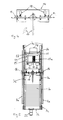
- Fig. 1 zeigt einen Aufzugsschacht 1 mit Zugangstüren 1a und einem Aufzug 2. Der Aufzug 2 umfasst eine Kabine 3 mit Kabinenwänden 4 und zumindest einer Kabi-nentür 5 an einer Frontseite. Zum Führen der Kabinenbe-wegung ist am Aufzugsschacht eine erste Füh-rungsvorrichtung 6 befestigt. Die erste Füh-rungsvorrichtung 6 umfasst vor-zugsweise zwei erste Führungsprofile 6a, die bei den Kabinenwänden 4 beidseits der Kabinentür 5 im mittleren Kabinenbereich angeordnet sind. An den Führungsprofilen 6a sind Führungsschuhe 3a der Kabine 3 geführt.
- Um die nötige Antriebskraft zu reduzieren ist ein Gegengewicht 7 in einer zweiten Füh-rungsvorrichtung 8 geführt. Die zweite Füh-rungsvorrichtung 8 umfasst vorzugsweise zwei zweite Führungsprofile 8a, die bei einer an die Kabinentür 5 anschliessenden Wand 4 neben dem ersten Führungsprofil 6a angeordnet sind.
- Ein Antrieb 10 zum Antreiben eines Seiles 9, bzw. eines Stahlseiles, ist am Gegenge-wicht 7 angeordnet. In der dargestellten Ausführungsform verläuft seine Antriebsachse 10a im Wesentlichen parallel zu einer Ebene durch die dem Gegengewicht 7 zuge-wandte Kabinenwand 4. Der Antrieb 10 ist getriebelos und umfasst eine um die An-triebsachse 10a verlaufende Aussenläufer-Hülse 11. Der Durchmesser der Aussenläu-fer-Hülse 11 ist kleiner als die Ausdehnung des Antriebs 10 in Richtung der An-triebsachse 10a. Das Seil 9 ist mit einer Umschlingung von mindestens 180° um die Aussenläufer-Hülse 11 gewickelt. Zur Aufnahme des Seiles 9 umfasst die Aussenläufer-Hülse 11 aussen Seilrillen 11a, die vorzugsweise nitriert sind.
- Der Antrieb 10 ist so dimensioniert, dass der Durchmesser der Aussenläufer-Hülse 11 kleiner ist als die Ausdehnung des Antriebs 10 in Richtung der Antriebsachse 10a. Der Durchmesser der Aussenläufer-Hülse 11 ist kleiner als 320mm und beträgt vorzugs-weise im Wesentlichen 240mm. Wenn die Antriebsachse 10a im Wesentlichen horizon-tal ausgerichtet ist, so beträgt die Ausdehnung des Antriebs 10 in Richtung der An-triebsachse 10a weniger als 700mm, vorzugsweise im Wesentlichen 600mm. Aufgrund des kleinen Durchmessers der Aussenläufer-Hülse 11, wird als Seil 9 ein Stahlseil ein-gesetzt, dessen Durchmesser maximal 8mm, vorzugsweise aber im Wesentlichen 6mm beträgt.
- Der Antrieb umfasst einen elektrischen Synchronmotor mit Permanentmagneten, wobei die Permanentmagneten gegen innen an der Aussenläufer-Hülse 11 und die Wicklungen zum Erzeugen des elektromagnetischen Feldes am Stator innerhalb der Aussenläufer-Hülse 11 angeordnet sind.
- Zum gleichzeitigen Bewegen der Kabine 3 sowie des Gegengewichtes 7 ist das Seil 9 mit beiden Enden am oberen Ende des Aufzugsschachtes 1 befestigt, wobei in der Figur nur eine der beiden Befestigungen 9b - nämlich über dem Gegengewicht 7 - dargestellt ist. Ausgehend von der Befestigung 9b über dem Gegengewicht 7 bildet das Seil 9 beim Gegengewicht 7 eine Schlaufe 9a, führt dann über zwei Umlenkrollen 12 am oberen Ende des Aufzugsschachtes 1 zu einer Schlaufe 9a bei der Kabine 3. Es versteht sich von selbst, dass die Schlaufe des Gegengewichtes 7 auch eine Flaschenzuganordnung umfassen kann, so dass sich das Gegengewicht 7 nur über einen Anteil, beispielsweise die Hälfte, der Schachthöhe bewegt.
- Die Seilschlaufe 9a mit der Kabine 3 führt von einer oberen Umlenkrolle 12 über zwei Umlenkrollen 12 unterhalb der Kabine 3 zu einer nicht dargestellten Befestigung 9b am oberen Ende des Aufzugsschachtes 1. Die Seilschlaufe 9a mit dem Gegengewicht 7 führt von der dargestellten Befestigung 9b über die Umschlingung der Aussenläufer-Hülse 11 zu einer oberen Umlenkrolle 12. Der Durchmesser der Umlenkrollen 12 ent-spricht im Wesentlichen dem Durchmesser der Aussenläufer-Hülse 11 und ist somit klein. Umlenkrollen 12 mit kleinem Durchmesser erlauben es, die Schachthöhe über der obersten Station und die Schachtgrubentiefe unter der untersten Station zu minimieren.
- Zum Bremsen bzw. Halten der Kabine 3 an einer gewünschten Position werden Brems-elemente 13 von einer Anpresseinrichtung an die Aussenläufer-Hülse 11 gepresst. Min-destens ein Freigabe-Elekromagnet wird zum Lösen der Bremselemente 13 eingesetzt. Der mindestens eine Freigabe-Elekromagnet ist über eine Schaltvorrichtung mit einem Akku verbunden. Der Akku und die Schaltvorrichtung ermöglichen auch bei einem Aus-fall der Netzspannung das Lösen der Bremselemente 13. Damit die Kabine 3 bei gelös-ten Bremselementen 13 keine unerwünscht schnelle Bewegung ausführt, sind Kurz-schlussbrücken einschaltbar, welche bei ausgeschalteter Antriebsspeisung, gelösten Bremselementen 13 sowie drehender Aussenläufer-Hülse 11 durch die Generatorwir-kung des Antriebes 10 eine Bremsung erzielen und dadurch für eine Notbefreiung eine langsame Kabinenbewegung ermöglichen.
- Für eine Speisung des Antriebs 10 sowie eine Übertragung von Steuersignalen zwi-schen dem Gegengewicht 7 und ortsfesten Steuerungselementen in einem Steuer-schrank ist ein erstes Schleppkabel 19 vorgesehen. Ein zweites Schleppkabel verbindet die Kabine 3 mit dem Steuerschrank, so dass die Stromversorgung der Kabine und die Übertragung von Steuer- und Anzeigesignalen zwischen Kabine und Steuerung ge-währleistet ist. Die Schleppkabel sind beispielsweise als vielpolige Flachbandkabel aus-gebildet. Der Steuerschrank ist vorzugsweise bei der untersten Station (nicht dargestellt, weil hinter der Kabine 3), gegebenenfalls aber bei einer anderen Station, oder auch vom Schacht 1 entfernt angeordnet. Zur Antriebsregelung wird vorzugsweise ein feldorien-tierter, stromgeregelter Frequenzumrichter mit Geberrückführung eingesetzt, welcher im Steuerschrank vorzugsweise aber am Gegengewicht 7 angeordnet ist.
- Die Fahrbewegungen des Gegengewichtes 7 führen bei den am Gegengewicht 7 ange-ordneten Komponenten zu einer Kühlung. Es wird zumindest der Antriebsmotor des Gegengewichtes 7 vom Fahrtwind gekühlt. Wenn auch der Frequenzumrichter beim Gegengewicht 7 angeordnet ist, so wird auch der Frequenzumrichter vom Fahrtwind gekühlt. Zusätzlich zur Fahrtwindkühlung wird gegebenenfalls auch eine Fremdbe-lüftung eingebaut.
- Der Antrieb und gegebenenfalls der Frequenzumrichter tragen zur Masse des Ge-gengewichtes bei, so dass zusätzliche Ausgleichs-Gewichtselemente 7a eingespart werden. Der ge-samte Materialaufwand wird reduziert. Wenn der Frequenzumrichter direkt beim An-trieb eingesetzt ist, so vereinfacht sich die Verkabelung zwischen An-trieb und Fre-quenzumrichter.
- Der Aufzug benötigt keinen Maschinenraum für den Antrieb und reduziert den Mate-rialbedarf, sowie die Herstellungs- und Montagekosten. Das Gegengewicht 7 um-fasst einen einfach aufgebauten Rahmen 7b, an dem der Antrieb 10 und auch an-dere Komponenten, wie beispielsweise eine Arretiervorrichtung 14, beim Gegenge-wicht 7 befestigt sind. Um Geräuschübertragungen vom Antrieb 10 auf das Gegen-gewicht zu eliminieren, kann der Antrieb 10 über Dämpfungs-elemente mit dem Rahmen 7b verbunden werden. Einsparungen können bei der Mon-tage erzielt wer-den, wenn das Gegengewicht 7 mit dem integrierten Antrieb 10 als vor-fabriziertes Fertigbauteil auf die Baustelle geliefert wird.
- Am unteren Schachtende sind Puffer 21 für die Kabine und für das Gegengewicht ausgebildet.
- Fig. 3 zeigt eine Aufzugsteuerung AS, die mit einem Frequenzumwandler FU und einer Bremsvorrichtung B verbunden ist. Die Bremsvorrichtung B umfasst Bremselemente, die von einer Anpresseinrichtung an die Aussenläufer-Hülse 11 des Elektromotors M ge-presst werden, und mindestens einen Freigabe-Elektromagneten zum Lösen der Brems-elemente. Um die Kabine in Bewegung zu setzen, veranlasst die Aufzugsteuerung AS das Lösen der Bremselemente und das in Bewegung setzen des Motors M über den Frequenzumwandler FU.
- Eine Rückholsteuerung RS ist mit einem Akku AK und der Bremsvorrichtung B verbun-den. Das Lösen der Bremsvorrichtung B kann über den Akku AK erzielt werden. Mit dieser Anordnung wird bei Stromausfall eine Rückholmöglichkeit bereitgestellt.
- Im normalen Betriebsmodus des Aufzugs wird der Akku AK permanent aufgeladen. Bei jeder Anfahrt des Aufzugs wird die Bremsvorrichtung B deblockiert, sofern der Akku AK genügend geladen ist. Bei ungenügender Ladung bleibt der Aufzug in der Station blockiert und geht in einen Störungsmodus. Im Störungsmodus öffnen sich Kabinen- und Schachttür und bleiben geöffnet bis die Störung behoben ist. Dadurch wird das Einschliessen von Personen verhindert.
- Bei einer allfälligen Betriebsstörung, bei der die Kabine 3 zwischen zwei Haltestellen 1a blockiert ist, wird ein Notbetrieb ermöglicht. Bei vorhandener Stromversorgung kann eine instruierte Person die Rückholsteuerung RS einschalten. Dabei wird die Kabine 3 über entsprechende Fahrrichtungstaster auf die nächstliegende Haltestelle 1a gefah-ren. Mit dem Notentriegelungsschlüssel kann beim Standort der Kabine 3 manuell die Schacht- und Kabinentüre geöffnet werden, um die eingeschlossenen Personen zu befreien.
- Bei ausgefallener Stromversorgung wird der Hauptschalter ausgeschaltet, um bei einer plötzlichen Rückkehr der Stromversorgung einen gefährlichen Betriebszustand zu verhindern. Anschliessend wird über die Rückholsteuerung RS die Bremsvor-richtung B gelöst. Durch den Freilauf des Antriebes 10 wird sich die Kabine automa-tisch, entspre-chend der Kabinenbeladung auf- oder abwärts in die nächstliegende Haltestelle 1a be-wegen. Bei diesem Notbetrieb werden Kurzschlussbrücken einge-schaltet, so dass durch die Generatorwirkung des Antriebes 10 eine Bremsung erzielt wird.
- Fig. 4 zeigt die Arretiervorrichtung 14 mit zwei beweglichen Eingriffselementen 15. An der zweiten Füh-rungsvorrichtung 8, bzw. an den Führungsprofilen 8a, ist zumindest an einer Wartungsposition mindestens eine Konsole 16 befestigt. Die Arretiervorrichtung 14 ist am Gegengewicht 7 befestigt. Für eine Sicherung bei Wartungsarbeiten kann das min-destens eine bewegliche Eingriffselement 15 zum Arretieren des Gegengewichtes 7 in Eingriff mit der mindestens einen Konsole 16 gebracht werden. Dazu wird beispiels-weise ein Hebel 17 der Arretiervorrichtung 14 betätigt. Um die Sicherheit zu erhöhen, werden die Eingriffselemente 15 durch elektromechanische Zwangskontakte 18 über-wacht, wobei die ermittelten Positionen der Eingriffselemente 15 vorzugsweise an die Steuerung AS übermittelt werden.
- Für Kontroll- und Wartungsarbeiten am Antrieb 10, wird die Kabine 3 auf eine Höhe et-was unter dem Gegengewicht 7 gefahren und die Arbeiten können vom Kabinen-dach aus bequem vorgenommen werden. Für umfangreichere Arbeiten wird das Ge-gen-gewicht 7 mit der Arretiervorrichtung 14 arretiert. Für die Sicherheit im normalen Be-triebszustand und für die sichere Ausführung der Wartungsarbeiten, werden die Po-sitionen die Schiebebolzen 15 von der Steuerung AS überwacht.
- Die beschriebene Ausführungsform gewährleistet eine einfache Notbefreiung und eine sichere Wartung des Antriebs.
- Fig. 5 zeigt den Rahmen 7b mit zwei vertikalen und zwei horizontalen Rahmenteilen. Am unteren horizontalen Rahmenteil ist ein Fuss 22 angeordnet, der einem Puffer 21 des Aufzugsschachtes 1 zugeordnet ist. Am oberen horizontalen Rahmenteil ist der Antrieb 10 befestigt. Das Gehäuse des dargestellten Antriebes 10 umfasst eine mit dem Rah-men 7b verbundene horizontale Befestigungsplatte 23 und an beiden Enden der Be-festigungsplatte 23 nach unten stehende stirnseitige Abschlussplatten 24. Die Abschlussplatten 24 sind fest mit dem Stator und über eine Drehlagerung mit der Aussen-läufer-Hülse (11) verbunden. Eine elektrische Anschlusseinrichtung 25 des Antriebes 10 steht seitlich über eine der Abschlussplatten 23 vor. Ebenfalls mit dem Rahmen 7b verbunden, gege-benenfalls über die Befestigungsplatte 23, ist der Frequenzumwandler FU. Zur Speisung des Antriebes 10 gelangt elektrische Energie vom Frequenzumwandler FU zur An-schlusseinrichtung 25.
- Die Arretiervorrichtung 14 ist zwischen dem Antrieb 10 und den Ausgleichs-Gewichts-elemente 7a am Rahmen 7b befestigt. An den Führungsprofilen 8a sind zum Arre-tie-ren des Gegengewichtes 7 mindestens je eine Konsole 16 gebracht. Die Führung des Rahmens 7b an den Führungsprofilen 8a erfolgt über zweite Führungsschuhe 7c.
- Der Rahmen 7b wird vorzugsweise mit Arretiervorrichtung 14, Antrieb 10, Frequenzum-wandler FU und Verkabelung auf die Baustelle geliefert, wodurch die bauseitige Mon-tage erleich-tert wird. Der Rahmen 7b wird über die Führungsschuhe 7c an den zweiten Führungs-profilen 8a gelagert. Das Seil 9 wird mit der gewünschten Umschlingung in die Seilrillen 11a eingelegt, um die Umlenkrollen 12 geführt und an beiden Enden oben im Aufzugs-schacht befestigt. Anschliessend werden die benötigten Ausgleichs-Gewichts-elemente 7a eingesetzt. Unerkannter Text
-
Claims (11)
- Aufzug mit einer Kabine (3), die Kabinenwände (4) und zumindest an einer Front-seite eine Kabi-nentür (5) umfasst, einer ersten Füh-rungsvorrichtung (6) zum Führen der Kabinenbe-wegung, einem Gegengewicht (7), einer zweiten Füh-rungsvorrichtung (8) zum Führen der Be-wegung des Gegengewichts (7), mindestens einem Seil (9) zum gleichzeitigen Bewegen der Kabine (3) sowie des Gegengewichtes (7) und einem Antrieb (10) zum Antreiben des Seiles (9), wobei das Seil (9) an beiden En-den ortsfest angeordnet ist, bei der Kabine (3) und beim Gegengewicht (7) eine nach unten hängende Schlaufe (9a) bildet und zwischen den Schlaufen (9a) über mindesten eine obere Umlenkrolle (12) geführt ist, da-durch gekennzeichnet, dass der Antrieb (10) am Gegengewicht (7) angeordnet ist, seine Antriebsachse (10a) im Wesentlichen parallel zu einer Ebene durch die dem Gegengewicht (7) zugewandte Kabinenwand (4) verläuft, der Antrieb (10) getriebelos ist und um die Antriebsachse (10a) eine Aussenläufer-Hülse (11) umfasst, wobei der Durchmesser der Aussen-läufer-Hülse (11) kleiner ist als die Ausdehnung des Antriebs (10) in Richtung der Antriebsachse (10a) und das Seil (9) mit einer Umschlingung von mindestens 180° um die Aussenläufer-Hülse (11) verläuft.
- Aufzug nach Anspruch 1, dadurch gekennzeichnet, dass der Durchmesser der Aus-senläufer-Hülse (11) kleiner als 320mm ist, vorzugsweise im Wesentlichen 240mm beträgt.
- Aufzug nach Anspruch 1 oder 2, dadurch gekennzeichnet, dass die Antriebsachse (10a) im Wesentlichen horizontal ausgerichtet ist und die Ausdehnung des Antriebs (10) in Richtung der Antriebsachse (10a) weniger als 700mm, vorzugsweise im We-sentlichen 600mm, beträgt.
- Aufzug nach einem der Ansprüche 1 bis 3, dadurch gekennzeichnet, dass der An-trieb (10) einen elektrischen Synchronmotor mit Permanentmagneten umfasst, wo-bei die Permanentmagneten gegen innen an der Aussenläufer-Hülse (11) und die Wicklungen zum Erzeugen des elektromagnetischen Feldes am Stator innerhalb der Aussenläufer-Hülse (11) angeordnet sind.
- Aufzug nach einem der Ansprüche 1 bis 4, dadurch gekennzeichnet, dass der Durch-messer des Seiles (9) maximal 8mm, vorzugsweise aber im Wesentlichen 6mm beträgt.
- Aufzug nach einem der Ansprüche 1 bis 5, dadurch gekennzeichnet, dass die min-destens eine Kabi-nentür (5) Schiebeelemente umfasst, die im geöffneten Zustand der Kabi-nentür (5) auf einer ersten Seite über eine anschliessende erste Kabinen-wand (4) hinaus in einen Vorstehbereich vorstehen und das Gegengewicht (7) seit-lich an die erste Kabinenwand (4) anschliessend in diesem Vorstehbereich ange-ordnet ist, wobei im Vorstehbereich ein Führungsprofil (6a) der ersten Füh-rungsvor-richtung (6) und daneben zwei Führungsprofile (8a) der zweiten Füh-rungsvorrich-tung (8) angeordnet sind.
- Aufzug nach einem der Ansprüche 1 bis 6, dadurch gekennzeichnet, dass Brems-elemente (13) von einer Anpresseinrichtung an die Aussenläufer-Hülse (11) ge-presst sind und mindestens ein Freigabe-Elektromagnet zum Lösen der Brems-elemente (13) eingesetzt ist.
- Aufzug nach Anspruch 7, dadurch gekennzeichnet, dass der mindestens eine Frei-gabe-Elektromagnet über eine Rückholsteuerung (RS) mit einem Akku (AK) verbun-den ist, der Akku und die Rückholsteuerung (RS) auch bei einem Ausfall der Netz-spannung die Bremselemente (13) lösbar machen, Kurzschlussbrücken einschaltbar sind, welche bei ausgeschalteter Antriebsspeisung, gelösten Bremselementen (13) sowie drehender Aussenläufer-Hülse (11) durch die Generatorwirkung des Antrie-bes (10) eine Bremsung erzielen und dadurch für eine Notbefreiung eine langsame Kabinenbewegung ermöglichen.
- Aufzug nach einem der Ansprüche 1 bis 8, dadurch gekennzeichnet, dass zumin-dest auf einer Wartungsposition an der zweiten Füh-rungsvorrichtung (8) mindestens eine Konsole (16) befestigt ist und am Gegengewicht (7) mindestens ein bewegli-ches Eingriffselement (15) angeordnet ist, wobei zum Arretieren des Gegengewich-tes (7) an der zweiten Füh-rungsvorrichtung (8) das mindestens eine Eingriffs-element (15) in Eingriff mit der mindestens einen Konsole (16) gebracht wird.
- Aufzug nach einem der Ansprüche 1 bis 9, dadurch gekennzeichnet, dass für eine Speisung des Antriebs (10) sowie eine Übertragung von Steuersignalen vom Ge-gengewicht (7) ein Schleppkabel (19) zu einem ortsfesten Steuerschrank führt und zur Antriebsregelung ein Frequenzumrichter (FU) mit Geberrückführung eingesetzt ist, welcher gegebenenfalls im Steuerschrank, vorzugsweise aber am Gegengewicht (7) angeordnet ist.
- Aufzug nach einem der Ansprüche 1 bis 10, dadurch gekennzeichnet, dass zwi-schen den Schlaufen (9a) zwei obere Umlenkrollen (12) eingesetzt sind, deren Durchmesser im Wesentlichen dem Durchmesser der Aussenläufer-Hülse (11) ent-sprechen.
Priority Applications (1)
| Application Number | Priority Date | Filing Date | Title |
|---|---|---|---|
| EP06117751.5A EP1882668B1 (de) | 2006-07-24 | 2006-07-24 | Aufzug mit Antrieb am Gegengewicht |
Applications Claiming Priority (1)
| Application Number | Priority Date | Filing Date | Title |
|---|---|---|---|
| EP06117751.5A EP1882668B1 (de) | 2006-07-24 | 2006-07-24 | Aufzug mit Antrieb am Gegengewicht |
Publications (2)
| Publication Number | Publication Date |
|---|---|
| EP1882668A1 true EP1882668A1 (de) | 2008-01-30 |
| EP1882668B1 EP1882668B1 (de) | 2023-08-30 |
Family
ID=38089164
Family Applications (1)
| Application Number | Title | Priority Date | Filing Date |
|---|---|---|---|
| EP06117751.5A Expired - Lifetime EP1882668B1 (de) | 2006-07-24 | 2006-07-24 | Aufzug mit Antrieb am Gegengewicht |
Country Status (1)
| Country | Link |
|---|---|
| EP (1) | EP1882668B1 (de) |
Cited By (4)
| Publication number | Priority date | Publication date | Assignee | Title |
|---|---|---|---|---|
| EP2174903A3 (de) * | 2008-10-12 | 2010-04-28 | H. Henseler AG | Aus der Liftkabine wartbarer Antrieb für eine Liftkabine |
| WO2010054570A1 (zh) * | 2008-11-17 | 2010-05-20 | Lv Anwen | 升降装置 |
| EP2497739A1 (de) | 2011-03-10 | 2012-09-12 | Hansruedi Diethelm | Aufzug |
| CN112158707A (zh) * | 2020-09-28 | 2021-01-01 | 扬州伟铧电梯有限公司 | 轿厢驱动式升降电梯 |
Citations (7)
| Publication number | Priority date | Publication date | Assignee | Title |
|---|---|---|---|---|
| FR2505574A1 (fr) * | 1981-05-07 | 1982-11-12 | Elevator Gmbh | Moteur a cage d'ecureuil avec convertisseur commande de frequence |
| EP0606875A1 (de) * | 1993-01-11 | 1994-07-20 | Kone Oy | Aufzugsmotor im Gegengewicht eingesetzt |
| JPH07117957A (ja) * | 1993-10-28 | 1995-05-09 | Mitsubishi Electric Corp | エレベーター装置 |
| EP0878430A2 (de) * | 1997-05-16 | 1998-11-18 | Baumüller Nürnberg Gmbh | Hebevorrichtung, insbesondere Aufzug, mit einem Elektromotor und Verwendung des Elektromotors |
| EP1085643A2 (de) * | 1999-09-13 | 2001-03-21 | Cobianchi Liftteile Ag | Permanentmagnet-Synchronmotor für Fahrstuhlantrieb |
| JP2003104665A (ja) * | 2001-09-28 | 2003-04-09 | Toshiba Elevator Co Ltd | エレベータ |
| EP1432104A2 (de) * | 2002-12-16 | 2004-06-23 | ebm-papst St. Georgen GmbH & Co. KG | Aussenläufermotor mit stehender Lagerachse |
-
2006
- 2006-07-24 EP EP06117751.5A patent/EP1882668B1/de not_active Expired - Lifetime
Patent Citations (7)
| Publication number | Priority date | Publication date | Assignee | Title |
|---|---|---|---|---|
| FR2505574A1 (fr) * | 1981-05-07 | 1982-11-12 | Elevator Gmbh | Moteur a cage d'ecureuil avec convertisseur commande de frequence |
| EP0606875A1 (de) * | 1993-01-11 | 1994-07-20 | Kone Oy | Aufzugsmotor im Gegengewicht eingesetzt |
| JPH07117957A (ja) * | 1993-10-28 | 1995-05-09 | Mitsubishi Electric Corp | エレベーター装置 |
| EP0878430A2 (de) * | 1997-05-16 | 1998-11-18 | Baumüller Nürnberg Gmbh | Hebevorrichtung, insbesondere Aufzug, mit einem Elektromotor und Verwendung des Elektromotors |
| EP1085643A2 (de) * | 1999-09-13 | 2001-03-21 | Cobianchi Liftteile Ag | Permanentmagnet-Synchronmotor für Fahrstuhlantrieb |
| JP2003104665A (ja) * | 2001-09-28 | 2003-04-09 | Toshiba Elevator Co Ltd | エレベータ |
| EP1432104A2 (de) * | 2002-12-16 | 2004-06-23 | ebm-papst St. Georgen GmbH & Co. KG | Aussenläufermotor mit stehender Lagerachse |
Cited By (4)
| Publication number | Priority date | Publication date | Assignee | Title |
|---|---|---|---|---|
| EP2174903A3 (de) * | 2008-10-12 | 2010-04-28 | H. Henseler AG | Aus der Liftkabine wartbarer Antrieb für eine Liftkabine |
| WO2010054570A1 (zh) * | 2008-11-17 | 2010-05-20 | Lv Anwen | 升降装置 |
| EP2497739A1 (de) | 2011-03-10 | 2012-09-12 | Hansruedi Diethelm | Aufzug |
| CN112158707A (zh) * | 2020-09-28 | 2021-01-01 | 扬州伟铧电梯有限公司 | 轿厢驱动式升降电梯 |
Also Published As
| Publication number | Publication date |
|---|---|
| EP1882668B1 (de) | 2023-08-30 |
Similar Documents
| Publication | Publication Date | Title |
|---|---|---|
| EP1305249B1 (de) | Aufzugskabine mit einer in diese integrierten treibscheiben-antriebsmaschine | |
| EP3807205B1 (de) | Verfahren zum errichten einer aufzugsanlage | |
| EP2496509B1 (de) | Aufzug | |
| DE69403684T2 (de) | Aufzugsmotor im Gegengewicht eingesetzt | |
| DE29615921U1 (de) | Anordnung zum Lösen der Bremse einer Aufzugmaschine | |
| EP4077193B1 (de) | Verfahren zum zentrierung einer aufzugskabine einer aufzugsanlage | |
| EP1118575A2 (de) | Aufzugsanlage mit im Aufzugsschacht angeordneter Antriebseinheit | |
| EP2709941B1 (de) | Aufzugsystem | |
| EP1882668B1 (de) | Aufzug mit Antrieb am Gegengewicht | |
| EP1069068B1 (de) | Kompakter Antrieb für einen Aufzug | |
| EP0926093B1 (de) | Aufzug, insbesondere Treibscheibenaufzug | |
| EP1566358A1 (de) | Triebwerksraumloser Treibscheibenaufzug | |
| EP4392637A1 (de) | Antriebsanordnung für ein hubtor mit einem rohrmotor auf einer statischen welle, hubtor und verfahren zum betreiben eines hubtores | |
| EP3153454B1 (de) | Türverschluss | |
| DE102008049379A1 (de) | Notbefreiungssystem für Aufzüge | |
| DE102017004719A1 (de) | Vorrichtung für einen gesicherten Bereich in einem Aufzugschacht | |
| DE102007016815A1 (de) | Schiebetürsystem | |
| DE19902853C2 (de) | Personen-Seilaufzug | |
| EP2303751B1 (de) | Aufzuganlage mit selbstfahrendem gegengewicht | |
| DE102011118544A1 (de) | Hilfsantrieb für Fahrkörbe von Aufzugsanlagen | |
| EP2500310A1 (de) | Aufzuganlage | |
| DE3722305A1 (de) | Aufzug mit linearmotor | |
| EP2960197A1 (de) | Mechanische notfall-aufwicklung für ein elektrisch betriebene blend- und sonnenschutzsysteme | |
| EP1122203A1 (de) | Seil-Aufzug | |
| DE10357035A1 (de) | Aufzuganlage mit schwenkbarer Fahrkorbschürze |
Legal Events
| Date | Code | Title | Description |
|---|---|---|---|
| PUAI | Public reference made under article 153(3) epc to a published international application that has entered the european phase |
Free format text: ORIGINAL CODE: 0009012 |
|
| AK | Designated contracting states |
Kind code of ref document: A1 Designated state(s): AT BE BG CH CY CZ DE DK EE ES FI FR GB GR HU IE IS IT LI LT LU LV MC NL PL PT RO SE SI SK TR |
|
| AX | Request for extension of the european patent |
Extension state: AL BA HR MK YU |
|
| 17P | Request for examination filed |
Effective date: 20080514 |
|
| 17Q | First examination report despatched |
Effective date: 20080711 |
|
| TPAC | Observations filed by third parties |
Free format text: ORIGINAL CODE: EPIDOSNTIPA |
|
| AKX | Designation fees paid |
Designated state(s): AT BE BG CH CY CZ DE DK EE ES FI FR GB GR HU IE IS IT LI LT LU LV MC NL PL PT RO SE SI SK TR |
|
| STAA | Information on the status of an ep patent application or granted ep patent |
Free format text: STATUS: EXAMINATION IS IN PROGRESS |
|
| GRAP | Despatch of communication of intention to grant a patent |
Free format text: ORIGINAL CODE: EPIDOSNIGR1 |
|
| STAA | Information on the status of an ep patent application or granted ep patent |
Free format text: STATUS: GRANT OF PATENT IS INTENDED |
|
| INTG | Intention to grant announced |
Effective date: 20220714 |
|
| GRAJ | Information related to disapproval of communication of intention to grant by the applicant or resumption of examination proceedings by the epo deleted |
Free format text: ORIGINAL CODE: EPIDOSDIGR1 |
|
| STAA | Information on the status of an ep patent application or granted ep patent |
Free format text: STATUS: EXAMINATION IS IN PROGRESS |
|
| INTC | Intention to grant announced (deleted) | ||
| GRAP | Despatch of communication of intention to grant a patent |
Free format text: ORIGINAL CODE: EPIDOSNIGR1 |
|
| STAA | Information on the status of an ep patent application or granted ep patent |
Free format text: STATUS: GRANT OF PATENT IS INTENDED |
|
| INTG | Intention to grant announced |
Effective date: 20230216 |
|
| GRAS | Grant fee paid |
Free format text: ORIGINAL CODE: EPIDOSNIGR3 |
|
| GRAA | (expected) grant |
Free format text: ORIGINAL CODE: 0009210 |
|
| STAA | Information on the status of an ep patent application or granted ep patent |
Free format text: STATUS: THE PATENT HAS BEEN GRANTED |
|
| AK | Designated contracting states |
Kind code of ref document: B1 Designated state(s): AT BE BG CH CY CZ DE DK EE ES FI FR GB GR HU IE IS IT LI LT LU LV MC NL PL PT RO SE SI SK TR |
|
| REG | Reference to a national code |
Ref country code: GB Ref legal event code: FG4D Free format text: NOT ENGLISH |
|
| REG | Reference to a national code |
Ref country code: CH Ref legal event code: EP |
|
| P01 | Opt-out of the competence of the unified patent court (upc) registered |
Effective date: 20230804 |
|
| REG | Reference to a national code |
Ref country code: DE Ref legal event code: R096 Ref document number: 502006016496 Country of ref document: DE |
|
| REG | Reference to a national code |
Ref country code: IE Ref legal event code: FG4D Free format text: LANGUAGE OF EP DOCUMENT: GERMAN |
|
| REG | Reference to a national code |
Ref country code: LT Ref legal event code: MG9D |
|
| REG | Reference to a national code |
Ref country code: NL Ref legal event code: MP Effective date: 20230830 |
|
| PG25 | Lapsed in a contracting state [announced via postgrant information from national office to epo] |
Ref country code: GR Free format text: LAPSE BECAUSE OF FAILURE TO SUBMIT A TRANSLATION OF THE DESCRIPTION OR TO PAY THE FEE WITHIN THE PRESCRIBED TIME-LIMIT Effective date: 20231201 |
|
| PG25 | Lapsed in a contracting state [announced via postgrant information from national office to epo] |
Ref country code: IS Free format text: LAPSE BECAUSE OF FAILURE TO SUBMIT A TRANSLATION OF THE DESCRIPTION OR TO PAY THE FEE WITHIN THE PRESCRIBED TIME-LIMIT Effective date: 20231230 |
|
| PG25 | Lapsed in a contracting state [announced via postgrant information from national office to epo] |
Ref country code: SE Free format text: LAPSE BECAUSE OF FAILURE TO SUBMIT A TRANSLATION OF THE DESCRIPTION OR TO PAY THE FEE WITHIN THE PRESCRIBED TIME-LIMIT Effective date: 20230830 Ref country code: LV Free format text: LAPSE BECAUSE OF FAILURE TO SUBMIT A TRANSLATION OF THE DESCRIPTION OR TO PAY THE FEE WITHIN THE PRESCRIBED TIME-LIMIT Effective date: 20230830 Ref country code: LT Free format text: LAPSE BECAUSE OF FAILURE TO SUBMIT A TRANSLATION OF THE DESCRIPTION OR TO PAY THE FEE WITHIN THE PRESCRIBED TIME-LIMIT Effective date: 20230830 Ref country code: IS Free format text: LAPSE BECAUSE OF FAILURE TO SUBMIT A TRANSLATION OF THE DESCRIPTION OR TO PAY THE FEE WITHIN THE PRESCRIBED TIME-LIMIT Effective date: 20231230 Ref country code: GR Free format text: LAPSE BECAUSE OF FAILURE TO SUBMIT A TRANSLATION OF THE DESCRIPTION OR TO PAY THE FEE WITHIN THE PRESCRIBED TIME-LIMIT Effective date: 20231201 Ref country code: FI Free format text: LAPSE BECAUSE OF FAILURE TO SUBMIT A TRANSLATION OF THE DESCRIPTION OR TO PAY THE FEE WITHIN THE PRESCRIBED TIME-LIMIT Effective date: 20230830 |
|
| PG25 | Lapsed in a contracting state [announced via postgrant information from national office to epo] |
Ref country code: PL Free format text: LAPSE BECAUSE OF FAILURE TO SUBMIT A TRANSLATION OF THE DESCRIPTION OR TO PAY THE FEE WITHIN THE PRESCRIBED TIME-LIMIT Effective date: 20230830 Ref country code: NL Free format text: LAPSE BECAUSE OF FAILURE TO SUBMIT A TRANSLATION OF THE DESCRIPTION OR TO PAY THE FEE WITHIN THE PRESCRIBED TIME-LIMIT Effective date: 20230830 |
|
| PG25 | Lapsed in a contracting state [announced via postgrant information from national office to epo] |
Ref country code: ES Free format text: LAPSE BECAUSE OF FAILURE TO SUBMIT A TRANSLATION OF THE DESCRIPTION OR TO PAY THE FEE WITHIN THE PRESCRIBED TIME-LIMIT Effective date: 20230830 |
|
| PG25 | Lapsed in a contracting state [announced via postgrant information from national office to epo] |
Ref country code: RO Free format text: LAPSE BECAUSE OF FAILURE TO SUBMIT A TRANSLATION OF THE DESCRIPTION OR TO PAY THE FEE WITHIN THE PRESCRIBED TIME-LIMIT Effective date: 20230830 Ref country code: ES Free format text: LAPSE BECAUSE OF FAILURE TO SUBMIT A TRANSLATION OF THE DESCRIPTION OR TO PAY THE FEE WITHIN THE PRESCRIBED TIME-LIMIT Effective date: 20230830 Ref country code: EE Free format text: LAPSE BECAUSE OF FAILURE TO SUBMIT A TRANSLATION OF THE DESCRIPTION OR TO PAY THE FEE WITHIN THE PRESCRIBED TIME-LIMIT Effective date: 20230830 Ref country code: DK Free format text: LAPSE BECAUSE OF FAILURE TO SUBMIT A TRANSLATION OF THE DESCRIPTION OR TO PAY THE FEE WITHIN THE PRESCRIBED TIME-LIMIT Effective date: 20230830 Ref country code: CZ Free format text: LAPSE BECAUSE OF FAILURE TO SUBMIT A TRANSLATION OF THE DESCRIPTION OR TO PAY THE FEE WITHIN THE PRESCRIBED TIME-LIMIT Effective date: 20230830 Ref country code: SK Free format text: LAPSE BECAUSE OF FAILURE TO SUBMIT A TRANSLATION OF THE DESCRIPTION OR TO PAY THE FEE WITHIN THE PRESCRIBED TIME-LIMIT Effective date: 20230830 Ref country code: PT Free format text: LAPSE BECAUSE OF FAILURE TO SUBMIT A TRANSLATION OF THE DESCRIPTION OR TO PAY THE FEE WITHIN THE PRESCRIBED TIME-LIMIT Effective date: 20240102 |
|
| REG | Reference to a national code |
Ref country code: DE Ref legal event code: R097 Ref document number: 502006016496 Country of ref document: DE |
|
| PLBE | No opposition filed within time limit |
Free format text: ORIGINAL CODE: 0009261 |
|
| STAA | Information on the status of an ep patent application or granted ep patent |
Free format text: STATUS: NO OPPOSITION FILED WITHIN TIME LIMIT |
|
| PG25 | Lapsed in a contracting state [announced via postgrant information from national office to epo] |
Ref country code: SI Free format text: LAPSE BECAUSE OF FAILURE TO SUBMIT A TRANSLATION OF THE DESCRIPTION OR TO PAY THE FEE WITHIN THE PRESCRIBED TIME-LIMIT Effective date: 20230830 |
|
| 26N | No opposition filed |
Effective date: 20240603 |
|
| PG25 | Lapsed in a contracting state [announced via postgrant information from national office to epo] |
Ref country code: BG Free format text: LAPSE BECAUSE OF FAILURE TO SUBMIT A TRANSLATION OF THE DESCRIPTION OR TO PAY THE FEE WITHIN THE PRESCRIBED TIME-LIMIT Effective date: 20230830 |
|
| PG25 | Lapsed in a contracting state [announced via postgrant information from national office to epo] |
Ref country code: BG Free format text: LAPSE BECAUSE OF FAILURE TO SUBMIT A TRANSLATION OF THE DESCRIPTION OR TO PAY THE FEE WITHIN THE PRESCRIBED TIME-LIMIT Effective date: 20230830 |
|
| PG25 | Lapsed in a contracting state [announced via postgrant information from national office to epo] |
Ref country code: MC Free format text: LAPSE BECAUSE OF FAILURE TO SUBMIT A TRANSLATION OF THE DESCRIPTION OR TO PAY THE FEE WITHIN THE PRESCRIBED TIME-LIMIT Effective date: 20230830 |
|
| PG25 | Lapsed in a contracting state [announced via postgrant information from national office to epo] |
Ref country code: LU Free format text: LAPSE BECAUSE OF NON-PAYMENT OF DUE FEES Effective date: 20240724 |
|
| GBPC | Gb: european patent ceased through non-payment of renewal fee |
Effective date: 20240724 |
|
| PG25 | Lapsed in a contracting state [announced via postgrant information from national office to epo] |
Ref country code: LU Free format text: LAPSE BECAUSE OF NON-PAYMENT OF DUE FEES Effective date: 20240724 |
|
| PG25 | Lapsed in a contracting state [announced via postgrant information from national office to epo] |
Ref country code: BE Free format text: LAPSE BECAUSE OF NON-PAYMENT OF DUE FEES Effective date: 20240731 |
|
| PG25 | Lapsed in a contracting state [announced via postgrant information from national office to epo] |
Ref country code: GB Free format text: LAPSE BECAUSE OF NON-PAYMENT OF DUE FEES Effective date: 20240724 |
|
| REG | Reference to a national code |
Ref country code: BE Ref legal event code: MM Effective date: 20240731 |
|
| PG25 | Lapsed in a contracting state [announced via postgrant information from national office to epo] |
Ref country code: IE Free format text: LAPSE BECAUSE OF NON-PAYMENT OF DUE FEES Effective date: 20240724 |
|
| PGFP | Annual fee paid to national office [announced via postgrant information from national office to epo] |
Ref country code: DE Payment date: 20250722 Year of fee payment: 20 |
|
| PGFP | Annual fee paid to national office [announced via postgrant information from national office to epo] |
Ref country code: IT Payment date: 20250731 Year of fee payment: 20 |
|
| PGFP | Annual fee paid to national office [announced via postgrant information from national office to epo] |
Ref country code: FR Payment date: 20250723 Year of fee payment: 20 Ref country code: AT Payment date: 20250721 Year of fee payment: 20 |
|
| PGFP | Annual fee paid to national office [announced via postgrant information from national office to epo] |
Ref country code: CH Payment date: 20250801 Year of fee payment: 20 |
|
| PG25 | Lapsed in a contracting state [announced via postgrant information from national office to epo] |
Ref country code: CY Free format text: LAPSE BECAUSE OF FAILURE TO SUBMIT A TRANSLATION OF THE DESCRIPTION OR TO PAY THE FEE WITHIN THE PRESCRIBED TIME-LIMIT; INVALID AB INITIO Effective date: 20060724 |
|
| PG25 | Lapsed in a contracting state [announced via postgrant information from national office to epo] |
Ref country code: HU Free format text: LAPSE BECAUSE OF FAILURE TO SUBMIT A TRANSLATION OF THE DESCRIPTION OR TO PAY THE FEE WITHIN THE PRESCRIBED TIME-LIMIT; INVALID AB INITIO Effective date: 20060724 |
|
| PG25 | Lapsed in a contracting state [announced via postgrant information from national office to epo] |
Ref country code: TR Free format text: LAPSE BECAUSE OF FAILURE TO SUBMIT A TRANSLATION OF THE DESCRIPTION OR TO PAY THE FEE WITHIN THE PRESCRIBED TIME-LIMIT Effective date: 20230830 |
|
| REG | Reference to a national code |
Ref country code: CH Ref legal event code: H14 Free format text: ST27 STATUS EVENT CODE: U-0-0-H10-H14 (AS PROVIDED BY THE NATIONAL OFFICE) Effective date: 20260724 Ref country code: DE Ref legal event code: R071 Ref document number: 502006016496 Country of ref document: DE |