EP1085643A2 - Permanentmagnet-Synchronmotor für Fahrstuhlantrieb - Google Patents
Permanentmagnet-Synchronmotor für Fahrstuhlantrieb Download PDFInfo
- Publication number
- EP1085643A2 EP1085643A2 EP00119758A EP00119758A EP1085643A2 EP 1085643 A2 EP1085643 A2 EP 1085643A2 EP 00119758 A EP00119758 A EP 00119758A EP 00119758 A EP00119758 A EP 00119758A EP 1085643 A2 EP1085643 A2 EP 1085643A2
- Authority
- EP
- European Patent Office
- Prior art keywords
- air
- motor according
- shaft
- fan
- flow
- Prior art date
- Legal status (The legal status is an assumption and is not a legal conclusion. Google has not performed a legal analysis and makes no representation as to the accuracy of the status listed.)
- Withdrawn
Links
- 230000001360 synchronised effect Effects 0.000 title claims abstract description 8
- 238000009423 ventilation Methods 0.000 claims abstract description 16
- 238000001816 cooling Methods 0.000 claims description 9
- 230000002093 peripheral effect Effects 0.000 claims description 6
- 238000004804 winding Methods 0.000 claims description 6
- 241000239290 Araneae Species 0.000 claims description 4
- 230000002269 spontaneous effect Effects 0.000 claims description 4
- 239000006185 dispersion Substances 0.000 claims 1
- 239000000725 suspension Substances 0.000 description 5
- 239000003638 chemical reducing agent Substances 0.000 description 3
- 238000010586 diagram Methods 0.000 description 3
- 230000002411 adverse Effects 0.000 description 1
- 230000001143 conditioned effect Effects 0.000 description 1
- 239000000428 dust Substances 0.000 description 1
- 230000000694 effects Effects 0.000 description 1
- 230000008030 elimination Effects 0.000 description 1
- 238000003379 elimination reaction Methods 0.000 description 1
- 238000005516 engineering process Methods 0.000 description 1
- 238000009434 installation Methods 0.000 description 1
- 238000005192 partition Methods 0.000 description 1
- 238000007493 shaping process Methods 0.000 description 1
Images



Classifications
-
- H—ELECTRICITY
- H02—GENERATION; CONVERSION OR DISTRIBUTION OF ELECTRIC POWER
- H02K—DYNAMO-ELECTRIC MACHINES
- H02K9/00—Arrangements for cooling or ventilating
- H02K9/02—Arrangements for cooling or ventilating by ambient air flowing through the machine
- H02K9/04—Arrangements for cooling or ventilating by ambient air flowing through the machine having means for generating a flow of cooling medium
Definitions
- the present invention regards an electric motor for moving lifts. More in particular, the present motor is devised with the aim of providing up to 1000 kg of lifting power or more, with a suspension ratio of 1:1, and up to 2000 kg or more, with a suspension ratio of 2:1, without any need for motion reducers.
- the present invention refers to applications in which the lift compartment may be hoisted up to 40 metres at a speed of up to 1.6 m/sec, without compensation of cable weight and at a speed of up to 2.5 m/sec or beyond with compensation of cable weight. In the latter case, the lift compartment can be hoisted up to 80 metres and beyond.
- the purpose of the present invention is to overcome the drawbacks referred to above and to propose a synchronous motor for lifts without motor reducers, characterized by a lifting capacity of more than 1000 kg and a suspension ratio of 1:1, and a lifting capacity of more than 2000 kg with a suspension ratio of 2:1.
- a further purpose of the invention is to provide a motor with high reliability and simplicity of operation.
- a permanent-magnet synchronous motor with external rotor in which the motor body is provided with inlet and outlet holes, through which, by means of a fan located inside, an air circulation is provided which cools the internal surfaces of both the stator and the rotor, and eliminates the desired amount of heat.
- the ventilation is of the forced type and is obtained by means of blades which are independent of the rotor shaft and are provided with a driving motor of its own.
- the air circulation is achieved by means of blades which are coaxial with and fixed to the motor shaft in such a way as to guarantee spontaneous ventilation during operation of the motor.
- a motor basically consists of a rotor 1 fixed to a central shaft 2.
- the rotor 1 is in the form of a cylindrical shell made up of a first section 4 on which is mounted a drive pulley 5 for moving the cables of the lift, and a second section 6 which has a diameter larger than the first section 4 and is joined to the latter by a wall 18 having the shape of an annulus.
- the larger section 6 is moreover provided with permanent magnets 7 arranged along its internal radial surface.
- the shaft 2 is fixed by means of screws 19 to the rotor 1 and is mounted on a pair of bearings 8 fitted in a central assembly 9 of the stator 10 of the motor.
- a central assembly 9 of the stator 10 of the motor Set radially with respect to the central assembly 9 are fins 11 enclosed within a cylindrical ring 12, outside which the stator windings 13 are made, the stator windings 13 being separated from the magnets 7 by an appropriate magnetic gap, whilst at the rear of the central assembly 9 an encoder 24 is provided, of a type in itself known.
- the motor is closed at the rear by a vertical flange 14 designed to be fixed to a wall when the motor is installed.
- the flange 14 is fixed by means of screws 15 to the ring 12 and is provided with a raised edge 16 which surrounds the mobile outer wall of the rotor 1 without ever coming into contact with the latter.
- a fan 17 in a position coaxial to the shaft 2, within the flange 14 a fan 17 is mounted, which is supplied autonomously and which causes a flow of air to pass through the inside of the motor body until it comes out through holes 20 made along the annulus-shaped wall 18, the holes 20 being made in the form of slots or circular holes sufficient in number to dissipate the heat.
- FIG. 2 illustrates in greater detail the ventilation scheme and the areas of thermal exchange of the heat generated by the rotor (area R) and the heat generated by the stator windings (area S).
- the heat generated is dissipated by the outer surface of the rotor, which is appropriately shaped, and is further dissipated by the flow of ventilating air which laps against the front wall before it comes out of the slots or holes 20.
- the fan has a running speed of 2800 r.p.m. for a flow rate of cooling air of 330 m 3 /h.
- the air flows along the spider structure of the stator which functions as a heatsink with guide ways for the air and presents an optimized surface to favour dissipation of heat.
- the flow of cooling air comes into contact with the front part of the windings and thus contributes to direct cooling of one of the hottest parts of the motor.
- the ventilation is controlled by a temperature sensor which enables the fan to go into action when the motor reaches a pre-set threshold temperature and stops the fan when the temperature has dropped back below the threshold value.
- a curved shield 22 is also provided, which is fixed at the front at the internal end of the central assembly 9 and in front of the fan 17.
- the shield 22 reduces the turbulence of flow arriving from the fan 17 and deflects it towards the fins of the stator, so improving heat exchange.
- the flange 14 For the fan 17 to have a sufficient intake of cool air, the flange 14 must be installed on a wall in such a way that an appropriate gap 21, of not less than approximately 150 mm, is left in between.
- the fan may act as a suction fan.
- the flow of air arrives from the slots or holes 20, traverses the inside of the motor, and comes out through the rear grill 50 in a direction opposite to that indicated by the arrows in Fig. 2.
- the fan is obtained by means of blades 17' fitted directly on a prolongation 23 of the shaft 2 in such a way as to guarantee a spontaneous ventilation during operation of the motor.
- the encoder 24 is fixed on the rear grill 50 and connected to the prolongation 23.
- the ventilation is effective only during operation of the motor and is conditioned by the speed of rotation of the rotor shaft.
- the elimination of heat achieved is sufficient to guarantee a considerable increase in torque as compared to traditional solutions.
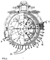
- the flow of incoming cool air impinges on the pockets 30 and is thus deflected, first radially and then axially, in a direction opposite to its incoming direction.
- the flow of air proceeds until it passes through the openings 31 made in the peripheral wall 12 of the body 32.
- the openings 31 communicate with the pockets 30 and have an outlet on the front edge of the body 32. Once the air has come out through the openings 31, it laps against the hot parts of the motor and proceeds along the peripheral circular wall of the motor until it encounters one or more external openings 34, from which it can be dissipated into the environment.
- the openings 34 basically face downwards and radially outwards in such a way that they can never pick up dust or other falling debris, whether the motor is installed vertically, as illustrated in Fig. 5, or installed horizontally.
Landscapes
- Engineering & Computer Science (AREA)
- Power Engineering (AREA)
- Load-Engaging Elements For Cranes (AREA)
- Permanent Magnet Type Synchronous Machine (AREA)
- Iron Core Of Rotating Electric Machines (AREA)
- Motor Or Generator Cooling System (AREA)
Applications Claiming Priority (2)
| Application Number | Priority Date | Filing Date | Title |
|---|---|---|---|
| IT1999FI000189A IT1308297B1 (it) | 1999-09-13 | 1999-09-13 | Motore sincrono a magneti permanenti per argani di ascensori |
| ITFI990189 | 1999-09-13 |
Publications (2)
| Publication Number | Publication Date |
|---|---|
| EP1085643A2 true EP1085643A2 (de) | 2001-03-21 |
| EP1085643A3 EP1085643A3 (de) | 2003-08-13 |
Family
ID=11353067
Family Applications (1)
| Application Number | Title | Priority Date | Filing Date |
|---|---|---|---|
| EP00119758A Withdrawn EP1085643A3 (de) | 1999-09-13 | 2000-09-11 | Permanentmagnet-Synchronmotor für Fahrstuhlantrieb |
Country Status (2)
| Country | Link |
|---|---|
| EP (1) | EP1085643A3 (de) |
| IT (1) | IT1308297B1 (de) |
Cited By (3)
| Publication number | Priority date | Publication date | Assignee | Title |
|---|---|---|---|---|
| WO2006007709A1 (en) * | 2004-07-20 | 2006-01-26 | Tm4 Inc. | Air cooled internal stator electric machine |
| EP1882668A1 (de) * | 2006-07-24 | 2008-01-30 | Hansruedi Diethelm | Aufzug mit Antrieb am Gegengewicht |
| NO20101347A1 (no) * | 2010-09-29 | 2012-03-30 | Rolls Royce Marine As | Elektrisk permanentmagnetmotor |
Family Cites Families (8)
| Publication number | Priority date | Publication date | Assignee | Title |
|---|---|---|---|---|
| JPS5768640A (en) * | 1980-10-15 | 1982-04-27 | Fanuc Ltd | Cooler for both directionally rotating motor |
| FR2515893B1 (fr) * | 1981-11-04 | 1986-03-28 | Marchal Equip Auto | Alternateur avec motoventilateur, pour vehicule automobile |
| FR2536222B1 (fr) * | 1982-11-15 | 1985-10-18 | Villeger Marcel | Alternateur annulaire |
| DE4130016A1 (de) * | 1990-12-24 | 1993-03-11 | Erich Rabe | Elektronisch kommutierte gleichstrommaschine |
| JPH07245925A (ja) * | 1994-03-01 | 1995-09-19 | Matsushita Electric Ind Co Ltd | ブラシレスモータ |
| IT1279098B1 (it) * | 1995-01-10 | 1997-12-04 | Bitron Spa | Perfezionamenti a motori di tipo brushless, in particolare per il pilotaggio diretto del cestello delle lavatrici |
| US5654598A (en) * | 1995-12-14 | 1997-08-05 | Siemens Electric Limited | Brushless motor with inside mounted single bearing |
| JPH10191593A (ja) * | 1996-12-24 | 1998-07-21 | Matsushita Electric Ind Co Ltd | ブラシレスモータ |
-
1999
- 1999-09-13 IT IT1999FI000189A patent/IT1308297B1/it active
-
2000
- 2000-09-11 EP EP00119758A patent/EP1085643A3/de not_active Withdrawn
Non-Patent Citations (1)
| Title |
|---|
| None |
Cited By (4)
| Publication number | Priority date | Publication date | Assignee | Title |
|---|---|---|---|---|
| WO2006007709A1 (en) * | 2004-07-20 | 2006-01-26 | Tm4 Inc. | Air cooled internal stator electric machine |
| EP1882668A1 (de) * | 2006-07-24 | 2008-01-30 | Hansruedi Diethelm | Aufzug mit Antrieb am Gegengewicht |
| NO20101347A1 (no) * | 2010-09-29 | 2012-03-30 | Rolls Royce Marine As | Elektrisk permanentmagnetmotor |
| NO331965B2 (no) * | 2010-09-29 | 2012-05-14 | Rolls Royce Marine As | Elektrisk permanentmagnetmotor |
Also Published As
| Publication number | Publication date |
|---|---|
| IT1308297B1 (it) | 2001-12-10 |
| ITFI990189A0 (it) | 1999-09-13 |
| ITFI990189A1 (it) | 2001-03-13 |
| EP1085643A3 (de) | 2003-08-13 |
Similar Documents
| Publication | Publication Date | Title |
|---|---|---|
| CN116526753B (zh) | 一种具有复合散热方式的磁悬浮电机及磁悬浮鼓风机 | |
| US4742257A (en) | Totally enclosed fan cooled induction motor with improved cooling | |
| CN112994355A (zh) | 一种带吊挂结构的空水冷大功率永磁牵引电机 | |
| CN110460198A (zh) | 高速永磁电机 | |
| CN107086713B (zh) | 一种高效散热的风冷定转子电机 | |
| CN110768414A (zh) | 一种永磁电机的冷却结构 | |
| CN220421567U (zh) | 一种中空轴散热电机 | |
| CN212463011U (zh) | 一种磁悬浮电机 | |
| EP1085643A2 (de) | Permanentmagnet-Synchronmotor für Fahrstuhlantrieb | |
| CN112366865A (zh) | 一种涡轮散热型永磁电机转子 | |
| CN110011448A (zh) | 永磁电机、压缩机和空调器 | |
| CN211183621U (zh) | 一种电机外壳的降噪散热结构 | |
| JP2001178079A (ja) | 強制冷却式全閉形回転電機 | |
| CN115912728B (zh) | 一种高效率的同步电动机 | |
| CN216564682U (zh) | 一种全封闭双循环风冷电机结构 | |
| CN112713716B (zh) | 一种设有内外冷却风路的封闭式电机及电机机座 | |
| CN210536440U (zh) | 一种具有散热结构的永磁调速器 | |
| CN214707387U (zh) | 一种自带外冷却结构的ip55工业吊扇电机 | |
| CN209526615U (zh) | 一种基于电动机的机壳散热组件 | |
| CN115664091A (zh) | 电机 | |
| CN110098688B (zh) | 电机本体及电机 | |
| CN114583871A (zh) | 具有一级能效的电机壳体结构及其装配方法 | |
| CN108925121B (zh) | 散热结构、电控箱及空调 | |
| CN211377813U (zh) | 一种外转子离心风机电机 | |
| CN224083318U (zh) | 一种高速无刷电机的隐藏式散热结构 |
Legal Events
| Date | Code | Title | Description |
|---|---|---|---|
| PUAI | Public reference made under article 153(3) epc to a published international application that has entered the european phase |
Free format text: ORIGINAL CODE: 0009012 |
|
| AK | Designated contracting states |
Kind code of ref document: A2 Designated state(s): AT BE CH CY DE DK ES FI FR GB GR IE IT LI LU MC NL PT SE |
|
| AX | Request for extension of the european patent |
Free format text: AL;LT;LV;MK;RO;SI |
|
| PUAL | Search report despatched |
Free format text: ORIGINAL CODE: 0009013 |
|
| AK | Designated contracting states |
Designated state(s): AT BE CH CY DE DK ES FI FR GB GR IE IT LI LU MC NL PT SE |
|
| AX | Request for extension of the european patent |
Extension state: AL LT LV MK RO SI |
|
| RIC1 | Information provided on ipc code assigned before grant |
Ipc: 7H 02K 9/06 B Ipc: 7H 02K 9/04 A |
|
| AKX | Designation fees paid | ||
| REG | Reference to a national code |
Ref country code: DE Ref legal event code: 8566 |
|
| STAA | Information on the status of an ep patent application or granted ep patent |
Free format text: STATUS: THE APPLICATION IS DEEMED TO BE WITHDRAWN |
|
| 18D | Application deemed to be withdrawn |
Effective date: 20040214 |