EP1880773A1 - Streukopf, insbesondere zur Streuung eines oder mehrerer Haftmittel oder einer oder mehrerer Haftmittelmischungen - Google Patents
Streukopf, insbesondere zur Streuung eines oder mehrerer Haftmittel oder einer oder mehrerer Haftmittelmischungen Download PDFInfo
- Publication number
- EP1880773A1 EP1880773A1 EP07109635A EP07109635A EP1880773A1 EP 1880773 A1 EP1880773 A1 EP 1880773A1 EP 07109635 A EP07109635 A EP 07109635A EP 07109635 A EP07109635 A EP 07109635A EP 1880773 A1 EP1880773 A1 EP 1880773A1
- Authority
- EP
- European Patent Office
- Prior art keywords
- extrusion
- channels
- head according
- spreading head
- adhesives
- Prior art date
- Legal status (The legal status is an assumption and is not a legal conclusion. Google has not performed a legal analysis and makes no representation as to the accuracy of the status listed.)
- Granted
Links
- 239000000853 adhesive Substances 0.000 title claims abstract description 208
- 230000001070 adhesive effect Effects 0.000 title claims abstract description 208
- 230000007480 spreading Effects 0.000 title claims abstract description 116
- 238000003892 spreading Methods 0.000 title claims abstract description 116
- 239000000203 mixture Substances 0.000 title claims abstract description 32
- 238000001125 extrusion Methods 0.000 claims abstract description 231
- 239000012943 hotmelt Substances 0.000 claims abstract description 5
- 239000000758 substrate Substances 0.000 claims description 27
- 239000003054 catalyst Substances 0.000 claims description 26
- 238000003475 lamination Methods 0.000 claims description 4
- 239000010410 layer Substances 0.000 description 48
- 238000009826 distribution Methods 0.000 description 11
- 239000000463 material Substances 0.000 description 8
- 239000002699 waste material Substances 0.000 description 7
- 238000004519 manufacturing process Methods 0.000 description 6
- 239000002356 single layer Substances 0.000 description 5
- 238000004140 cleaning Methods 0.000 description 4
- 230000000670 limiting effect Effects 0.000 description 4
- 239000012528 membrane Substances 0.000 description 4
- 239000012790 adhesive layer Substances 0.000 description 3
- 238000004040 coloring Methods 0.000 description 3
- 230000000694 effects Effects 0.000 description 3
- 238000000034 method Methods 0.000 description 3
- 230000008569 process Effects 0.000 description 3
- 230000003213 activating effect Effects 0.000 description 2
- 230000004888 barrier function Effects 0.000 description 2
- 239000004744 fabric Substances 0.000 description 2
- 239000007788 liquid Substances 0.000 description 2
- 239000004033 plastic Substances 0.000 description 2
- 239000011347 resin Substances 0.000 description 2
- 229920005989 resin Polymers 0.000 description 2
- 239000000126 substance Substances 0.000 description 2
- 229920001169 thermoplastic Polymers 0.000 description 2
- 239000004416 thermosoftening plastic Substances 0.000 description 2
- 241000761557 Lamina Species 0.000 description 1
- 208000034809 Product contamination Diseases 0.000 description 1
- 239000000945 filler Substances 0.000 description 1
- 238000002347 injection Methods 0.000 description 1
- 239000007924 injection Substances 0.000 description 1
- 230000004048 modification Effects 0.000 description 1
- 238000012986 modification Methods 0.000 description 1
- 239000011148 porous material Substances 0.000 description 1
- 230000009467 reduction Effects 0.000 description 1
- 230000007704 transition Effects 0.000 description 1
Images


Classifications
-
- B—PERFORMING OPERATIONS; TRANSPORTING
- B05—SPRAYING OR ATOMISING IN GENERAL; APPLYING FLUENT MATERIALS TO SURFACES, IN GENERAL
- B05C—APPARATUS FOR APPLYING FLUENT MATERIALS TO SURFACES, IN GENERAL
- B05C5/00—Apparatus in which liquid or other fluent material is projected, poured or allowed to flow on to the surface of the work
- B05C5/02—Apparatus in which liquid or other fluent material is projected, poured or allowed to flow on to the surface of the work the liquid or other fluent material being discharged through an outlet orifice by pressure, e.g. from an outlet device in contact or almost in contact, with the work
- B05C5/0254—Coating heads with slot-shaped outlet
-
- B—PERFORMING OPERATIONS; TRANSPORTING
- B05—SPRAYING OR ATOMISING IN GENERAL; APPLYING FLUENT MATERIALS TO SURFACES, IN GENERAL
- B05C—APPARATUS FOR APPLYING FLUENT MATERIALS TO SURFACES, IN GENERAL
- B05C11/00—Component parts, details or accessories not specifically provided for in groups B05C1/00 - B05C9/00
- B05C11/10—Storage, supply or control of liquid or other fluent material; Recovery of excess liquid or other fluent material
- B05C11/1002—Means for controlling supply, i.e. flow or pressure, of liquid or other fluent material to the applying apparatus, e.g. valves
- B05C11/1026—Valves
-
- B—PERFORMING OPERATIONS; TRANSPORTING
- B05—SPRAYING OR ATOMISING IN GENERAL; APPLYING FLUENT MATERIALS TO SURFACES, IN GENERAL
- B05C—APPARATUS FOR APPLYING FLUENT MATERIALS TO SURFACES, IN GENERAL
- B05C5/00—Apparatus in which liquid or other fluent material is projected, poured or allowed to flow on to the surface of the work
- B05C5/02—Apparatus in which liquid or other fluent material is projected, poured or allowed to flow on to the surface of the work the liquid or other fluent material being discharged through an outlet orifice by pressure, e.g. from an outlet device in contact or almost in contact, with the work
- B05C5/0254—Coating heads with slot-shaped outlet
- B05C5/0258—Coating heads with slot-shaped outlet flow controlled, e.g. by a valve
-
- B—PERFORMING OPERATIONS; TRANSPORTING
- B05—SPRAYING OR ATOMISING IN GENERAL; APPLYING FLUENT MATERIALS TO SURFACES, IN GENERAL
- B05C—APPARATUS FOR APPLYING FLUENT MATERIALS TO SURFACES, IN GENERAL
- B05C9/00—Apparatus or plant for applying liquid or other fluent material to surfaces by means not covered by any preceding group, or in which the means of applying the liquid or other fluent material is not important
- B05C9/06—Apparatus or plant for applying liquid or other fluent material to surfaces by means not covered by any preceding group, or in which the means of applying the liquid or other fluent material is not important for applying two different liquids or other fluent materials, or the same liquid or other fluent material twice, to the same side of the work
-
- B—PERFORMING OPERATIONS; TRANSPORTING
- B05—SPRAYING OR ATOMISING IN GENERAL; APPLYING FLUENT MATERIALS TO SURFACES, IN GENERAL
- B05B—SPRAYING APPARATUS; ATOMISING APPARATUS; NOZZLES
- B05B7/00—Spraying apparatus for discharge of liquids or other fluent materials from two or more sources, e.g. of liquid and air, of powder and gas
- B05B7/02—Spray pistols; Apparatus for discharge
- B05B7/04—Spray pistols; Apparatus for discharge with arrangements for mixing liquids or other fluent materials before discharge
- B05B7/0408—Spray pistols; Apparatus for discharge with arrangements for mixing liquids or other fluent materials before discharge with arrangements for mixing two or more liquids
-
- B—PERFORMING OPERATIONS; TRANSPORTING
- B05—SPRAYING OR ATOMISING IN GENERAL; APPLYING FLUENT MATERIALS TO SURFACES, IN GENERAL
- B05B—SPRAYING APPARATUS; ATOMISING APPARATUS; NOZZLES
- B05B7/00—Spraying apparatus for discharge of liquids or other fluent materials from two or more sources, e.g. of liquid and air, of powder and gas
- B05B7/02—Spray pistols; Apparatus for discharge
- B05B7/12—Spray pistols; Apparatus for discharge designed to control volume of flow, e.g. with adjustable passages
- B05B7/1209—Spray pistols; Apparatus for discharge designed to control volume of flow, e.g. with adjustable passages the controlling means for each liquid or other fluent material being manual and interdependent
-
- Y—GENERAL TAGGING OF NEW TECHNOLOGICAL DEVELOPMENTS; GENERAL TAGGING OF CROSS-SECTIONAL TECHNOLOGIES SPANNING OVER SEVERAL SECTIONS OF THE IPC; TECHNICAL SUBJECTS COVERED BY FORMER USPC CROSS-REFERENCE ART COLLECTIONS [XRACs] AND DIGESTS
- Y10—TECHNICAL SUBJECTS COVERED BY FORMER USPC
- Y10T—TECHNICAL SUBJECTS COVERED BY FORMER US CLASSIFICATION
- Y10T156/00—Adhesive bonding and miscellaneous chemical manufacture
- Y10T156/17—Surface bonding means and/or assemblymeans with work feeding or handling means
- Y10T156/1798—Surface bonding means and/or assemblymeans with work feeding or handling means with liquid adhesive or adhesive activator applying means
Definitions
- the present invention relates to a spreading head particularly for spreading one or more adhesives or mixtures of adhesives, both of the hot-melt type and of the cold type.
- spreading devices which comprise one or more spreading heads provided with a duct for feeding the adhesive, the delivery end of which faces, during use, a substrate which is made to advance in close contact therewith in the form of a ribbon.
- the adhesive is introduced in the duct in the liquid state, typically by means of appropriately provided gear pumps, and can be applied either continuously or intermittently, by throttling the flow thereof by means of appropriately provided valves of a known type which are arranged in the spreading head.
- valves further allow to vary the width of the region of application of the adhesive and to perform throttlings of said adhesive, with a preset pitch, transversely to the ribbon of substrate.
- the variation of the width of the region of application of the adhesive can also be achieved by means of one or more inserts of a known type, which can be arranged automatically or manually within the duct so as to partially obstruct its cross-section, so as to adapt its width to the width of the tape.
- said known types of head allow to obtain only a uniform film of adhesive in contact with both surfaces of the materials to be coupled; this entails the need to use a high-value adhesive even if its use is required only by one of the two surfaces to be coupled, with an additional waste of material.
- the use of known types of head entails an additional waste of high-value adhesive, since said adhesive also acts as a filler for the pores of the substrate.
- known types of head are used to provide membranes which in some regions must have breathability characteristics, and therefore require low grammages of applied adhesive, and in other regions must instead provide a vapor barrier effect and therefore require high adhesive grammages; to obtain this embodiment, known types of head require a double passage over the substrate, which is performed either with different heads or with a same head which is modified at a later time, and this increases the production times, and therefore the production costs, of producing said membranes.
- thermoplastic adhesives since many thermoplastic adhesives have a residual stickiness after their spreading, it is not possible to apply them with a double pass.
- spreading heads which allow to apply a plurality of superimposed layers; however, said heads do not allow to perform combined applications, i.e., multilayer products in certain regions and single-layer products in other regions, and also do not allow intermittent and/or combined applications of the so-called "multiline" type.
- the aim of the present invention is to solve the above mentioned problems, eliminating the drawbacks of the cited background art, by providing a spreading head which allows to spread one or more adhesives onto a substrate, so as to obtain, in chosen regions thereof, layers of the chosen type of chosen adhesive and/or of the chosen grammage.
- an object of the invention is to provide a spreading head which allows to obtain, even in a single pass, the spreading onto a substrate of two or more superimposed layers of one or more adhesives.
- Another object of the invention is to allow the mixing of a plurality of adhesives or of an adhesive and a catalyst, limiting the head cleaning time and further reducing the waste of adhesive that has already been mixed with a catalyst if the spreading process is interrupted.
- Another object is to provide a spreading head which allows to achieve the spreading of one or more adhesives in a plurality of layers which are arranged side-by-side and optionally mutually spaced, in which each layer has the chosen characteristics of width and/or composition and/or grammage and/or number of superimposed layers that compose it.
- Another object of the invention is to facilitate the operations for cleaning the spreading head.
- Another object is to provide a spreading head which allows the spreading in rapid succession of adhesives having different chemical properties and/or colorings, which may even be mutually incompatible.
- Another object of the invention is to reduce the time and cost for producing membranes which have breathable regions and vapor-permeable regions.
- Another object of the invention is to reduce the waste of high-value adhesive in the process for spreading it onto a substrate, even a porous one.
- Another object of the invention is to achieve a reduction in the costs for spreading one or more adhesives onto a substrate.
- Another object is to provide a spreading head which is structurally simple and has low manufacturing costs.
- a spreading head particularly for spreading one or more adhesives or mixtures of adhesives, of the hot-melt or cold type, comprising a body for conveying said one or more adhesives to an extrusion tool, characterized in that said body has two or more ducts, which are all separate or of which two or more converge, and in that said tool has one or more first extrusion channels and/or one or more mixing chambers which are connected to one or more second extrusion channels, said first and/or second extrusion channels being optionally mutually superimposed and/or laterally adjacent.
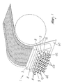
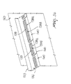
- the reference numeral 1 generally designates a spreading head, particularly for one or more adhesives or mixtures of adhesives, of the hot-melt or cold type, on an appropriately provided substrate 60 constituted for example by a tape made of fabric or plastic material.
- the spreading head 1 is constituted by a body 2 for conveying such one or more adhesives to an extrusion tool, designated by the reference numeral 3.
- the body 2 is approximately shaped like a parallelepiped with a transverse cross-section which is approximately shaped like a right-angled trapezoid.
- Two or more ducts are formed within the body 2; all of said ducts are separate or two or more of them converge.
- the body 2 has a first duct and a second duct, designated respectively by the reference numerals 4 and 5, which are approximately mutually parallel and affect longitudinally the body 2, preferably along most of its width; advantageously, the first and second ducts 4 and 5 respectively have one or more first and second accesses, designated respectively by the reference numerals 4' and 5', from which it is possible to introduce, for example by means of appropriately provided rotary pumps, not shown in the accompanying figures, one or more adhesives or mixtures of adhesives or catalysts for adhesives.
- first and second ducts 4 and 5 mutually converge inside the body 2; the first and second ducts 4 and 5 are connected respectively to first and second output ducts, designated respectively by the reference numerals 6 and 7, which converge in pairs, with the interposition of appropriately provided first and second valves of a known type, designated respectively by the reference numerals 8 and 9, within appropriately provided mixing channels 10, from each of which a first feed channel 11 protrudes which is connected in output to the extrusion tool 3.
- the first and second output ducts 6 and 7 are formed along axes which are substantially perpendicular to the first and second ducts 4 and 5; the first and second output ducts 6 and 7 are present in a chosen number and are distributed, in a preferably equidistant arrangement, respectively along the first and second ducts 4 and 5.
- the body 2 has a third duct 12, which is approximately parallel to the first and second ducts and again affects longitudinally the body 2 preferably along most of its width.
- the third duct 12 has one or more third accesses 13 for an adhesive or a mixture of adhesives or catalyst for adhesives.
- One or more second feed channels 14 exit from the third duct 12, are connected in output to the extrusion tool 3, and are connected to the third duct 12 by means of appropriately provided third valves 15 of a known type; advantageously, the outputs of the second feed channels 14 and of the first feed channels 11 are aligned along a same longitudinal axis with respect to the body 2.
- the second feed channels 14 are formed along axes which are substantially perpendicular to the longitudinal axis of the third duct 12; the second feed channels 14 are provided in a chosen number and are distributed, preferably in an equidistant configuration, along the third duct 12.
- the body 2 further has a fourth duct and a fifth duct, designated respectively by the reference numerals 16 and 17, which are approximately parallel to the first, second and third ducts and affect longitudinally the body 2 preferably along most of its width; the fourth and fifth duct 16 and 17 respectively have fourth and fifth accesses, designated respectively by the reference numerals 18 and 19, for an adhesive or a mixture of adhesives or catalysts for adhesives.
- the outputs of the third and fourth feed channels 20 and 21 are aligned respectively along two axes which are arranged longitudinally with respect to the body 2 and are substantially parallel and spaced with respect to each other and with respect to the axis along which the outputs of the first and second feed channels 11 and 14 are aligned.
- the third and fourth feed channels 20 and 21 are formed along axes which are substantially perpendicular respectively to the longitudinal axes of the fourth and fifth ducts 16 and 17; the third and fourth feed channels 20 and 21 are provided in a chosen number and are distributed, preferably equidistantly, respectively along the fourth and fifth ducts 16 and 17.
- the extrusion tool 3 is constituted by a lower element 24, which can be fixed to the contiguous body 2 and is preferably shaped approximately like a parallelepiped, with a transverse cross-section shaped like a right-angled trapezoid arranged so that its shorter parallel side 25 engages the body 2 and its longer parallel side 26 is directed away from it.
- One or more first extrusion channels are formed in the lower element 24 of the extrusion tool 3, and are optionally mutually superimposed and/or laterally adjacent; each channel is connected in input to one of the first and/or second and/or third and/or fourth feed channels which exit from the body 3.
- first extrusion channels 27a and 27b are connected respectively to the third feed channels 20 and to the fourth feed channels 21 formed within the body 2.
- first extrusion channels 27a and 27b which are mutually superimposed in pairs (i.e., are arranged parallel to each other and to the longitudinal axis of the lower element 24) and are also mutually laterally adjacent in pairs; hereinafter, the first extrusion channel 27a, which lies closest to the perimetric edge 26a of the longer parallel side 26 which during use is directed toward the substrate 60 will be also referenced as front channel, and the adjacent first extrusion channel 27b will be also referenced as rear channel.
- the longitudinal extension of the first extrusion channels 27a and 27b of each pair is identical, while the longitudinal extension of two laterally adjacent pairs of said first extrusion channels 27a and 27b may be different.
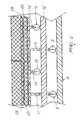
- each pair of first mutually superimposed extrusion channels 27a and 27b the outlet of the first extrusion channel arranged in a rearward position (the channel 27b with reference to Figure 3) is, with respect to the throttling plane, at a greater elevation than the adjacent first channel arranged in a forward position (the one designated in Figure 3 by the reference numeral 27a).
- the plane of arrangement of the first (front) extrusion channel 27a which is adjacent to the first (rear) extrusion channel 27b lies at a lower level than the first (rear) extrusion channel 27b, in order to allow to extrude two superimposed layers of adhesive which, after flowing out of the respective first channel 27a or 27b, remain one on top of the other due to their different relative densities.
- the additional first extrusion channels 27c extend from the perimetric edge 26a of the longer parallel side 26 of the lower element 24 which during use is directed toward the substrate 60; as described in greater detail hereinafter, this configuration of the first extrusion channels allows to obtain in output laterally adjacent layers of adhesive spaced by microlayers of reduced width.
- one or more mixing chambers 28 can further be provided in the lower element 24 of the extrusion tool 3, each chamber being connected to one or more second extrusion channels 29, which like the first extrusion channels 27a and 27b are optionally superimposed and/or laterally adjacent with respect to each other and/or with respect to the first extrusion channels 27a, 27b; in the example shown in the accompanying figures, the second extrusion channels 29 are mutually laterally adjacent, and each channel is superimposed on a pair of first extrusion channels 27a and 27b.
- the configuration and therefore the size of the second extrusion channels 29 follow those of the first extrusion channels 27a and 27b at each of the pairs of the channels on which they are superimposed.
- each second extrusion channel 29 is at a higher level than the adjacent first (rear) extrusion channel 27b, in order to allow the extrusion of three superimposed layers of adhesive which, after flowing out respectively from the second extrusion channel 29 and from the adjacent first extrusion channels 27a and 27b, remain one on top of the other due to their different relative densities.
- each mixing chamber 28 is connected to at least one of the first and at least one of the second feed channels 11 and 14 formed within the body 2; in this manner, it is possible to make two or more different adhesives (shown in Figure 6 by means of two shadings with opposite inclinations), or a chosen adhesive and the respective catalyst, converge in the mixing chambers 28 in order to achieve mixing directly within the extrusion tool 3.
- first extrusion channels 27a, 27b which are mutually superimposed and the adjacent second extrusion channels 29 may have mutually different extensions; thus, for example, as shown in Figures 3, 4 and 5, some pairs of first extrusion channels 27a and 27b which are mutually superimposed and the adjacent second extrusion channels 29 may have a shorter extension than the pairs of first extrusion channels 27a and 27b which are mutually superimposed and than the adjacent second extrusion channels 29, allowing to obtain in output layers of adhesive which are laterally adjacent and have different widths.
- a slit 30, provided preferably by removing material and so as to affect the outlet of at least the first (front) extrusion channels 27a: said slit arranges on a lower plane the outlet of the first (front) extrusion channel 27a with respect to the plane of arrangement of the first (rear) extrusion channel 27b and of the second extrusion channel 29.
- the slit 30 guides the outflow of the layer or layers of adhesive from the extrusion tool 3 onto the substrate 60.
- one or more of the first extrusion channels 27a, 27b and/or of the additional first extrusion channels 27c and/or of the second extrusion channels 29 may have, along an axis which lies longitudinally with respect to the lower element 24, reduced lengths so as to constitute microchannels which are designated by the reference numerals 50a and 50b.
- the microchannels 50a and 50b are arranged at right angles to the first and second extrusion channels, are mutually parallel and are interposed between two pairs of the first and second extrusion channels 27a, 27b and 29.
- the configuration of the microchannels 50a and 50b with respect to the longer parallel side 26 of the lower element 24 of the extrusion tool 3 is preferably comb-like, with teeth which advantageously have two different lengths and are arranged preferably alternately.
- the extrusion tool 3 further comprises an upper element 31, which can be fixed to the longer parallel side 26 of the lower element 24 and is preferably approximately shaped like a parallelepiped, with a transverse cross-section shaped like a right-angled trapezoid.
- the upper element 31 therefore acts as an abutment for the adhesive or adhesives that exit from the first and second channels formed in the lower element 24, thus guiding the adhesive or adhesives to exit from the slits 30.
- both the first valve 8 and the third valve 15 are open, in the mixing chamber 28 mixing occurs between the two adhesives or between the adhesive and the catalyst, contained respectively in the first and third ducts; from the mixing chamber 28, through the second extrusion channel 29, the mixture of adhesives or the adhesive mixed with the catalyst is then extruded by the extrusion tool 3 through the slit 30.
- This distribution of the layers of adhesive in output can also be achieved with a simplified configuration of the spreading head 1 in which the body 2 has only the first duct 4 and the third duct 12, from which a corresponding number of first and second feed channels 11 and 14 exit respectively through one or more first valves 8 and third valves 15.
- the extrusion tool 3 does not have the first extrusion channels but only one or more mixing chambers 28, each of which is connected in input to a first feed channel 11 and to a second feed channel 14 and in output to a second channel 29; as shown in Figure 11, the various second extrusion channels 29 in this case are mutually laterally adjacent.
- the distribution of the adhesive layers in output can also be achieved with a simplified configuration of the spreading head 1, in which the body 2 has only the third duct 12 and the fourth duct 16, from which a corresponding number of second and third feed channels 14 and 20 protrude respectively through one or more third valves 15 and fourth valves 22.
- the extrusion tool 3 is not provided with the mixing chambers 28 but only, as shown in Figures 13, 15 and 16, with the microchannels 50a and 50b, which are arranged in a comb-like configuration, are mutually alternated and are connected in input respectively to the second feed channels 14 and to the third feed channels 20.
- this distribution of the layers of adhesive in output can also be achieved with a simplified configuration of the spreading head 1, in which the body 2 has only the third duct 12 and the fourth duct 16, from which a corresponding number of second and third feed channels 14 and 20 exit respectively through one or more third valves 15 and fourth valves 22.
- the extrusion tool 3 does not have the first extrusion channels below the second extrusion channels 29 but has only the additional first extrusion channels 27c, which are smaller and are arranged between the latter.
- this distribution of the layers of adhesive in output can also be achieved with a simplified configuration of the spreading head 1, in which the body 2 has only the third duct 12 and the fourth duct 16, from which a corresponding number of second and third feed channels 14 and 20 exit respectively through one or more third valves 15 and fourth valves 22.
- the extrusion tool 3 has only a series of first extrusion channels 27b which are arranged below the second extrusion channels 29; one adhesive or the other can be fed respectively to a first channel 27b or to the overlying second extrusion channel 29 by opening or closing the respective fourth and third valves.
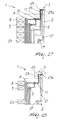
- the adhesive or adhesives and the catalyst contained respectively in the first and second ducts enter the mixing channel 10, from which they exit, after being mixed, by means of the first extrusion channels 11, entering the mixing chambers 28 of the extrusion tool 3 and finally exiting from it by means of the second extrusion channels 29.
- the adhesive contained in the fifth duct 17 enters the fourth feed channels 21 and then exits from the first (front) extrusion channels 27a arranged below the second extrusion channels 29.
- the adhesive that exits from the second extrusion channels 29 and the adhesive that exits from the underlying first (front) extrusion channels 27a are extruded simultaneously; said adhesives remain one on top of the other due to their different relative densities, thus forming a double layer, designated in Figure 30 by the reference numeral 34, which is composed of a lower layer 34a of the first adhesive (which arrives from the fourth feed channels 21) and an upper layer 34b of the second adhesive (which arrives from the first feed channels 11).
- this distribution of the adhesive layers in output can also be achieved with a simplified configuration of the spreading head 1 in which the body 2 has only the first duct 4 and the second duct 5 which mutually converge in a suitable mixing channel 10 with the interposition of the first and second valves; the body 2 further has the fifth duct 17 which is connected, by means of the fifth valves 23, to the fourth feed channels 21.
- the extrusion tool 3 has only one series of first extrusion channels 27a which are arranged below the second extrusion channels 29.
- the three adhesives thus exit simultaneously respectively from the first two extrusion channels 27a and 27b and from the second extrusion channel 29 so as to be mutually superimposed, forming a triple layer, designated in Figure 34 by the reference numeral 35, which is constituted by a lower layer 35a of the first adhesive (which arrives from the fourth feed channels 21), by an intermediate layer 35b of the second adhesive (which arrives from the third feed channels 20), and by an upper layer 35c of the third adhesive (or optionally again of the first adhesive) (which arrives from the second feed channels 14).
- this distribution of the layers of adhesives in output can also be achieved with a simplified configuration of the spreading head 1, in which the body 2 has only the third, fourth and fifth ducts and the respective third, fourth and fifth valves, through which said ducts are connected respectively to the second, third and fourth feed channels.
- the extrusion tool 3 has multiple pairs of first extrusion channels 27a and 27b which are arranged below a second extrusion channel 29 and are laterally mutually adjacent.
- a spreading head having been devised which allows to apply to chosen areas of a substrate a chosen adhesive and/or different adhesives and/or a same adhesive with different grammages and/or a multiple layer of adhesives.
- the spreading head according to the invention therefore allows to provide areas with differentiated grammage and also using differentiated adhesives, so as to be able to reduce (even by 70%, as has been found) the amount of (more expensive) structural adhesive that is required.
- the spreading head according to the invention allows to achieve the spreading on a substrate of a chosen number of layers of adhesive arranged side-by-side and having a chosen width.
- the spreading head according to the invention allows to mix various adhesives or an adhesive and a suitable catalyst both within the body and within the extrusion tool.
- the spreading head according to the invention further allows to use sequentially adhesives which are chemically compatible with each other, since before applying the new adhesive it is sufficient to replace the extrusion tool; this reduces machine downtime with respect to the
- the spreading head according to the invention allows in particular to achieve the mixing of the adhesives only in the extrusion tool, thus limiting the waste of already-mixed adhesive and the time required to clean the head, and further obviating product contaminations.
- the spreading head according to the invention allows to provide said mixing directly in the extrusion tool, and this solves all the problems of circuit cleaning and allows to avoid wasting already-mixed product in case of machine downtime.
- the spreading head By means of the spreading head according to the invention it is further possible to achieve, even in a single pass, the spreading of a multilayer film of adhesives, so as to be able to use products with a good grip on different substrates.
- the spreading head according to the invention allows to reduce the waste of "high-value” product, by making a low-cost resin perform the nonstructural function and making a thin layer of high-value resin perform the structural effect.
- the spreading head according to the invention allows to provide, even with a single pass, a membrane which has breathability characteristics in certain regions and a vapor barrier effect in others.
- the spreading head according to the invention is suitable for use for spreading thermoplastic adhesives and cold adhesives.
- the spreading head according to the invention allows the alternating application of hot and cold adhesives, since transition from one type of adhesive to the other merely entails replacing the extrusion tool.
- the production costs of the spreading head according to the invention remain low, since it is made of components which are easy to manufacture and/or assemble.
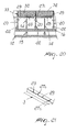
- Figures 35 and 36 illustrate a spreading head 101 in which the extrusion tool 103 is constituted by a single block which is preferably shaped, in a transverse cross-section, approximately like a right-angled trapezoid and is superimposed, with its lower surface 136, on the underlying upper surface 137 of the body 102 at the outlets of the first feed channel 111, of the second feed channel 114, of the third feed channel 120 and of the fourth feed channel 121.
- the first extrusion channels formed in the extrusion tool 103 are each constituted by a first cavity 138a, 138b, which is formed in the lower surface 136 of the extrusion tool 103 and faces the outlet of one of the first, second, third and fourth feed channels formed in the body 102.
- the first cavities 138b and 138a face respectively the third feed channels 120 and the fourth feed channels 121 formed within the body 102.
- first cavities 138a and 138b are shown which are arranged so as to be mutually superimposed in pairs (i.e., arranged parallel to each other and to the longitudinal axis of the extrusion tool 103) and are also laterally adjacent in pairs; hereinafter, the first cavity 138a which during use lies closest to the substrate 160 will also be referenced as front cavity and the adjacent first cavity 138b will be referenced also as rear cavity.
- each pair of first cavities 138a and 138b is identical, while the longitudinal extension of two laterally adjacent pairs of first cavities 138a and 138b may be different.
- each mixing chamber and the respective one or more second extrusion channels are constituted by a single second cavity 139, which is formed in the lower surface 136 of the extrusion tool 103 and faces the outlet of one of the first, second, third and fourth feed channels formed within the body 102.
- the second cavities 139 face respectively the first feed channels 111 and/or the second feed channels 114 which are formed within the body 102.
- each second cavity faces respectively at least one first feed channel 111 and at least one second feed channel 114, so as to allow the simultaneous introduction therein (and the consequent mixing therein) of two different adhesives or of an adhesive and a suitable catalyst.
- the second cavities 139 are optionally superimposed and/or laterally adjacent to each other and/or to the first cavities 138a, 138b; in the example shown in Figures 35 and 36, the second cavities 139 are mutually laterally adjacent, each cavity being superimposed on a pair of first cavities 138a and 138b.
- the shape, and therefore the size, of the second cavities 139 follows the shape and size of the first cavities 138a and 138b at each of the pairs thereof on which they are superimposed.
- first cavities 138a, 138b which are mutually superimposed and the adjacent second cavities 139 may have mutually different extensions; thus, for example, as shown in Figure 36, some pairs of first cavities 138a, 138b which are mutually superimposed and the adjacent second cavities 139 can have a shorter extension than the pairs of first cavities 138a and 138b which are mutually superimposed and of the second adjacent cavities 139, allowing to obtain in output laterally adjacent adhesive layers of different width.
- one or more recesses 140 are formed on the lower surface 136 of the extrusion tool 103, preferably by removing material and so that each one affects a pair of first cavities 138a, 138b which are mutually superimposed and the adjacent second cavities 139, said recesses being suitable to allow the outflow of the adhesive or of the mixture of adhesives from the extrusion tool 103.
- the one or more recesses 140 have a constant thickness and are formed along a plane which is approximately perpendicular to the lamination plane.
- the adhesive or mixture of adhesives or adhesive and catalyst thus converge in the chosen cavity among the first or second cavities, filling it until it overflows from it; once it has exited from the respective first or second cavity, the flow of adhesive or mixture of adhesives, depending on the position of the first or second cavity from which it flows out, can be extruded directly by the tool 103, through the recesses 140, or can optionally enter and then exit from the contiguous first and/or second cavities to be finally extruded through the recesses 140.
- the selection of the feed to the extrusion tool of the chosen type of adhesive and/or mixtures of adhesives and/or catalysts can occur not only by activating or not activating the mentioned preset valves but also by virtue of equivalent means, such as for example the interposition of appropriately provided plates which are selectively perforated between the body and the extrusion tool.
Landscapes
- Coating Apparatus (AREA)
- Extrusion Moulding Of Plastics Or The Like (AREA)
- Adhesives Or Adhesive Processes (AREA)
Applications Claiming Priority (1)
| Application Number | Priority Date | Filing Date | Title |
|---|---|---|---|
| IT000124A ITTV20060124A1 (it) | 2006-07-17 | 2006-07-17 | Struttura di testata di spalmatura, particolarmente di uno o piu' adesivi o miscele di adesivi |
Publications (2)
| Publication Number | Publication Date |
|---|---|
| EP1880773A1 true EP1880773A1 (de) | 2008-01-23 |
| EP1880773B1 EP1880773B1 (de) | 2014-03-19 |
Family
ID=38308726
Family Applications (1)
| Application Number | Title | Priority Date | Filing Date |
|---|---|---|---|
| EP07109635.8A Active EP1880773B1 (de) | 2006-07-17 | 2007-06-05 | Streukopf, insbesondere zur Streuung eines oder mehrerer Haftmittel oder einer oder mehrerer Haftmittelmischungen |
Country Status (4)
| Country | Link |
|---|---|
| US (1) | US8109229B2 (de) |
| EP (1) | EP1880773B1 (de) |
| ES (1) | ES2477117T3 (de) |
| IT (1) | ITTV20060124A1 (de) |
Cited By (8)
| Publication number | Priority date | Publication date | Assignee | Title |
|---|---|---|---|---|
| WO2011025603A1 (en) * | 2009-08-31 | 2011-03-03 | Illinois Tool Works Inc. | Metering system for simultaneously dispensing two different adhesives from a single metering device or applicator onto a common substrate |
| WO2012072576A1 (de) * | 2010-12-03 | 2012-06-07 | Baumer Hhs Gmbh | Vorrichtung zum auftragen von viskosen medien |
| EP2532444A1 (de) * | 2011-06-07 | 2012-12-12 | Baumer hhs GmbH | Verfahren und Vorrichtung zum Auftrag von viskosen oder fluiden Medien |
| WO2012139757A3 (de) * | 2011-04-12 | 2013-01-10 | Rwr Patentverwaltung Gbr | Vorrichtung, koextrusionsdüse und verfahren zum auftragen und/oder herstellen eines flächigen materialverbunds sowie flächiger materialverbund |
| WO2014143578A1 (en) * | 2013-03-12 | 2014-09-18 | Illinois Tool Works Inc. | Variable volume hot melt adhesive dispensing nozzle or die assembly with choke suppression |
| US9126222B2 (en) | 2009-07-17 | 2015-09-08 | Illinois Tool Works Inc. | Metering system for hot melt adhesives with variable adhesive volumes |
| US9718081B2 (en) | 2009-08-31 | 2017-08-01 | Illinois Tool Works Inc. | Metering system for simultaneously dispensing two different adhesives from a single metering device or applicator onto a common substrate |
| WO2019086705A3 (de) * | 2017-11-06 | 2019-07-25 | Tesa Se | Verfahren und vorrichtung zur herstellung eines klebebandes und vorrichtung hierfür |
Families Citing this family (6)
| Publication number | Priority date | Publication date | Assignee | Title |
|---|---|---|---|---|
| ITTV20060123A1 (it) * | 2006-07-17 | 2008-01-18 | Hip Mitsu Srl | Struttura di testata di spalmatura, particolarmente di uno o piu' adesivi o miscele di adesivi |
| KR20140086155A (ko) * | 2012-12-28 | 2014-07-08 | 현대자동차주식회사 | 전극막 조립체 제작용 슬롯다이코팅 장치 |
| DE102017122495A1 (de) | 2017-09-27 | 2019-03-28 | Dürr Systems Ag | Applikator mit einem geringen Düsenabstand |
| DE102017122493A1 (de) | 2017-09-27 | 2019-03-28 | Dürr Systems Ag | Applikator mit geringem Düsenabstand |
| MX2021013727A (es) * | 2019-05-10 | 2022-05-18 | Atn Hoelzel Gmbh | Metodo y dispositivo para la aplicación secuencial continua de dos o más fluidos o materiales viscosos. |
| CN112871574B (zh) * | 2021-01-11 | 2021-09-07 | 江西索雅纳科技股份有限公司 | 一种高效型耳机生产用线头焊胶设备 |
Citations (3)
| Publication number | Priority date | Publication date | Assignee | Title |
|---|---|---|---|---|
| US5075139A (en) * | 1989-06-24 | 1991-12-24 | Saint-Gobain Vitrage International | Coating process for coating transparent plastic coatings with a pigmented filter strip |
| EP1101537A1 (de) * | 1999-11-16 | 2001-05-23 | Hip High Industrial Performances S.r.l. | Beschihtungsvorrichtung, insbesondere für thermoplastisches Material |
| EP1316368A1 (de) | 2001-11-28 | 2003-06-04 | Illinois Tool Works Inc. | Durchflussregelsystem für einen Heissschmelzkleber |
Family Cites Families (7)
| Publication number | Priority date | Publication date | Assignee | Title |
|---|---|---|---|---|
| US2374069A (en) * | 1941-03-13 | 1945-04-17 | Du Pont | Method of plasticizing polyamides |
| US3508947A (en) * | 1968-06-03 | 1970-04-28 | Eastman Kodak Co | Method for simultaneously applying a plurality of coated layers by forming a stable multilayer free-falling vertical curtain |
| US3887322A (en) * | 1973-11-28 | 1975-06-03 | Arco Polymers Inc | Extruder die for multiple stream extrusion |
| US5120484A (en) * | 1991-03-05 | 1992-06-09 | The Cloeren Company | Coextrusion nozzle and process |
| US5769947A (en) * | 1994-10-22 | 1998-06-23 | Itw Dynatech Gmbh Klebetechnik | Applicator for adhesive and corresponding nozzle plate |
| US6467893B1 (en) * | 1998-12-28 | 2002-10-22 | Fuji Photo Film Co., Ltd. | Method and apparatus for forming image with plural coating liquids |
| US6837698B2 (en) * | 2001-12-19 | 2005-01-04 | 3M Innovative Properties Company | Multilayer coextrusion die and method |
-
2006
- 2006-07-17 IT IT000124A patent/ITTV20060124A1/it unknown
-
2007
- 2007-06-05 ES ES07109635.8T patent/ES2477117T3/es active Active
- 2007-06-05 EP EP07109635.8A patent/EP1880773B1/de active Active
- 2007-06-08 US US11/808,276 patent/US8109229B2/en not_active Expired - Fee Related
Patent Citations (3)
| Publication number | Priority date | Publication date | Assignee | Title |
|---|---|---|---|---|
| US5075139A (en) * | 1989-06-24 | 1991-12-24 | Saint-Gobain Vitrage International | Coating process for coating transparent plastic coatings with a pigmented filter strip |
| EP1101537A1 (de) * | 1999-11-16 | 2001-05-23 | Hip High Industrial Performances S.r.l. | Beschihtungsvorrichtung, insbesondere für thermoplastisches Material |
| EP1316368A1 (de) | 2001-11-28 | 2003-06-04 | Illinois Tool Works Inc. | Durchflussregelsystem für einen Heissschmelzkleber |
Cited By (17)
| Publication number | Priority date | Publication date | Assignee | Title |
|---|---|---|---|---|
| US9126222B2 (en) | 2009-07-17 | 2015-09-08 | Illinois Tool Works Inc. | Metering system for hot melt adhesives with variable adhesive volumes |
| WO2011025603A1 (en) * | 2009-08-31 | 2011-03-03 | Illinois Tool Works Inc. | Metering system for simultaneously dispensing two different adhesives from a single metering device or applicator onto a common substrate |
| US9718081B2 (en) | 2009-08-31 | 2017-08-01 | Illinois Tool Works Inc. | Metering system for simultaneously dispensing two different adhesives from a single metering device or applicator onto a common substrate |
| US9573159B2 (en) | 2009-08-31 | 2017-02-21 | Illinois Tool Works, Inc. | Metering system for simultaneously dispensing two different adhesives from a single metering device or applicator onto a common substrate |
| CN103269805A (zh) * | 2010-12-03 | 2013-08-28 | 堡盟Hhs有限公司 | 用于涂覆粘性介质的装置 |
| US9044764B2 (en) | 2010-12-03 | 2015-06-02 | Baumer Hhs Gmbh | Device for applying viscous media |
| CN103269805B (zh) * | 2010-12-03 | 2016-08-10 | 堡盟Hhs有限公司 | 用于涂覆粘性介质的装置 |
| WO2012072576A1 (de) * | 2010-12-03 | 2012-06-07 | Baumer Hhs Gmbh | Vorrichtung zum auftragen von viskosen medien |
| EP2697033A2 (de) * | 2011-04-12 | 2014-02-19 | RWR Patentverwaltung GbR | Vorrichtung, koextrusionsdüse und verfahren zum auftragen und/oder herstellen eines flächigen materialverbunds sowie flächiger materialverbund |
| CN103635299A (zh) * | 2011-04-12 | 2014-03-12 | Rwr专利管理公司 | 用于涂覆和/或制造面状的材料复合物的方法、设备和共挤喷嘴以及面状的材料复合物 |
| WO2012139757A3 (de) * | 2011-04-12 | 2013-01-10 | Rwr Patentverwaltung Gbr | Vorrichtung, koextrusionsdüse und verfahren zum auftragen und/oder herstellen eines flächigen materialverbunds sowie flächiger materialverbund |
| EP2697033B1 (de) * | 2011-04-12 | 2021-06-16 | ITW Dynatec GmbH | Vorrichtung und koextrusionsdüse zum auftragen und/oder herstellen eines flächigen materialverbunds |
| EP2532444A1 (de) * | 2011-06-07 | 2012-12-12 | Baumer hhs GmbH | Verfahren und Vorrichtung zum Auftrag von viskosen oder fluiden Medien |
| WO2014143578A1 (en) * | 2013-03-12 | 2014-09-18 | Illinois Tool Works Inc. | Variable volume hot melt adhesive dispensing nozzle or die assembly with choke suppression |
| WO2019086705A3 (de) * | 2017-11-06 | 2019-07-25 | Tesa Se | Verfahren und vorrichtung zur herstellung eines klebebandes und vorrichtung hierfür |
| CN111373007A (zh) * | 2017-11-06 | 2020-07-03 | 德莎欧洲股份公司 | 制造胶带的方法和设备以及用于此的设备 |
| CN111373007B (zh) * | 2017-11-06 | 2022-03-08 | 德莎欧洲股份公司 | 制造胶带的方法和设备以及用于此的设备 |
Also Published As
| Publication number | Publication date |
|---|---|
| US20080011227A1 (en) | 2008-01-17 |
| EP1880773B1 (de) | 2014-03-19 |
| US8109229B2 (en) | 2012-02-07 |
| ES2477117T3 (es) | 2014-07-15 |
| ITTV20060124A1 (it) | 2008-01-18 |
Similar Documents
| Publication | Publication Date | Title |
|---|---|---|
| US8109229B2 (en) | Spreading head particularly for spreading one or more adhesives or mixtures of adhesives | |
| EP1880772B1 (de) | Streukopf, insbesondere zur Streuung eines oder mehrerer Haftmittel oder einer oder mehrerer Haftmittelmischungen | |
| DE69917234T2 (de) | Segmentmatrize zum auftragen von heissschmelzklebstoffen oder anderen polymerschmelzen | |
| EP2473288B1 (de) | Dosiersystem zum gleichzeitigen ausgeben zwei verschiedener haftmittel aus einem einzigen dosierer oder auftraggerät auf ein substrat | |
| JPH04501540A (ja) | 合成樹脂多層フィルム又は―プレートを押出し成形するための装置 | |
| JP2001252544A (ja) | 静止混合機 | |
| WO2017135023A1 (ja) | 塗工装置 | |
| JP2002317328A5 (de) | ||
| ZA201005687B (en) | Curtain coater | |
| DE2245820C2 (de) | Strangpresse zum Verarbeiten plastischer, insbesondere thermoplastischer oder nicht vernetzter elastomerer Massen | |
| US20170259483A1 (en) | Coextrusion adapter | |
| JP2004216725A (ja) | タイヤの成型方法およびリボン状ゴム押出機 | |
| CN1228674A (zh) | 改进的涂敷模具 | |
| EP1101537B1 (de) | Beschichtungsvorrichtung, insbesondere für thermoplastisches Material | |
| KR20130051401A (ko) | 커튼 코터 | |
| JP2001310149A (ja) | ストライプ塗布用ダイセット、およびその方法ならびにストライプ塗布製品 | |
| KR20090083377A (ko) | 단열유리판의 두 유리패널 사이 공간 내에 페이스트 물질 스트랜드 주입 방법 및 장치 | |
| CA1200357A (en) | Extruding laminated sheet with alteration of stream dimensions in die | |
| JPS6313730A (ja) | 押出成形用複合アダプタ | |
| JP2016078012A (ja) | 塗布器 | |
| USRE27769E (en) | Apparatus for casting multi-layer composite film | |
| JP2015024557A (ja) | ゴムシート製造装置 | |
| JPH0732443A (ja) | 多層複合フィルム又はシート成形用フィードブロック | |
| JP2668843B2 (ja) | 多層複合フイルム又はシート成形用フイードブロック | |
| JPS5838309B2 (ja) | 多層複合体押出装置 |
Legal Events
| Date | Code | Title | Description |
|---|---|---|---|
| PUAI | Public reference made under article 153(3) epc to a published international application that has entered the european phase |
Free format text: ORIGINAL CODE: 0009012 |
|
| AK | Designated contracting states |
Kind code of ref document: A1 Designated state(s): AT BE BG CH CY CZ DE DK EE ES FI FR GB GR HU IE IS IT LI LT LU LV MC MT NL PL PT RO SE SI SK TR |
|
| AX | Request for extension of the european patent |
Extension state: AL BA HR MK YU |
|
| 17P | Request for examination filed |
Effective date: 20080610 |
|
| AKX | Designation fees paid |
Designated state(s): AT BE BG CH CY CZ DE DK EE ES FI FR GB GR HU IE IS IT LI LT LU LV MC MT NL PL PT RO SE SI SK TR |
|
| 17Q | First examination report despatched |
Effective date: 20090313 |
|
| GRAP | Despatch of communication of intention to grant a patent |
Free format text: ORIGINAL CODE: EPIDOSNIGR1 |
|
| INTG | Intention to grant announced |
Effective date: 20130510 |
|
| GRAS | Grant fee paid |
Free format text: ORIGINAL CODE: EPIDOSNIGR3 |
|
| GRAA | (expected) grant |
Free format text: ORIGINAL CODE: 0009210 |
|
| AK | Designated contracting states |
Kind code of ref document: B1 Designated state(s): AT BE BG CH CY CZ DE DK EE ES FI FR GB GR HU IE IS IT LI LT LU LV MC MT NL PL PT RO SE SI SK TR |
|
| REG | Reference to a national code |
Ref country code: GB Ref legal event code: FG4D |
|
| REG | Reference to a national code |
Ref country code: CH Ref legal event code: EP |
|
| REG | Reference to a national code |
Ref country code: IE Ref legal event code: FG4D |
|
| REG | Reference to a national code |
Ref country code: AT Ref legal event code: REF Ref document number: 657290 Country of ref document: AT Kind code of ref document: T Effective date: 20140415 |
|
| REG | Reference to a national code |
Ref country code: DE Ref legal event code: R096 Ref document number: 602007035628 Country of ref document: DE Effective date: 20140430 |
|
| REG | Reference to a national code |
Ref country code: CH Ref legal event code: NV Representative=s name: MODIANO AND PARTNERS SA, CH |
|
| REG | Reference to a national code |
Ref country code: ES Ref legal event code: FG2A Ref document number: 2477117 Country of ref document: ES Kind code of ref document: T3 Effective date: 20140715 |
|
| PG25 | Lapsed in a contracting state [announced via postgrant information from national office to epo] |
Ref country code: LT Free format text: LAPSE BECAUSE OF FAILURE TO SUBMIT A TRANSLATION OF THE DESCRIPTION OR TO PAY THE FEE WITHIN THE PRESCRIBED TIME-LIMIT Effective date: 20140319 |
|
| REG | Reference to a national code |
Ref country code: NL Ref legal event code: VDEP Effective date: 20140319 |
|
| REG | Reference to a national code |
Ref country code: AT Ref legal event code: MK05 Ref document number: 657290 Country of ref document: AT Kind code of ref document: T Effective date: 20140319 |
|
| REG | Reference to a national code |
Ref country code: LT Ref legal event code: MG4D |
|
| PG25 | Lapsed in a contracting state [announced via postgrant information from national office to epo] |
Ref country code: SE Free format text: LAPSE BECAUSE OF FAILURE TO SUBMIT A TRANSLATION OF THE DESCRIPTION OR TO PAY THE FEE WITHIN THE PRESCRIBED TIME-LIMIT Effective date: 20140319 Ref country code: CY Free format text: LAPSE BECAUSE OF FAILURE TO SUBMIT A TRANSLATION OF THE DESCRIPTION OR TO PAY THE FEE WITHIN THE PRESCRIBED TIME-LIMIT Effective date: 20140319 Ref country code: FI Free format text: LAPSE BECAUSE OF FAILURE TO SUBMIT A TRANSLATION OF THE DESCRIPTION OR TO PAY THE FEE WITHIN THE PRESCRIBED TIME-LIMIT Effective date: 20140319 |
|
| PG25 | Lapsed in a contracting state [announced via postgrant information from national office to epo] |
Ref country code: LV Free format text: LAPSE BECAUSE OF FAILURE TO SUBMIT A TRANSLATION OF THE DESCRIPTION OR TO PAY THE FEE WITHIN THE PRESCRIBED TIME-LIMIT Effective date: 20140319 |
|
| PG25 | Lapsed in a contracting state [announced via postgrant information from national office to epo] |
Ref country code: EE Free format text: LAPSE BECAUSE OF FAILURE TO SUBMIT A TRANSLATION OF THE DESCRIPTION OR TO PAY THE FEE WITHIN THE PRESCRIBED TIME-LIMIT Effective date: 20140319 Ref country code: NL Free format text: LAPSE BECAUSE OF FAILURE TO SUBMIT A TRANSLATION OF THE DESCRIPTION OR TO PAY THE FEE WITHIN THE PRESCRIBED TIME-LIMIT Effective date: 20140319 Ref country code: CZ Free format text: LAPSE BECAUSE OF FAILURE TO SUBMIT A TRANSLATION OF THE DESCRIPTION OR TO PAY THE FEE WITHIN THE PRESCRIBED TIME-LIMIT Effective date: 20140319 Ref country code: BG Free format text: LAPSE BECAUSE OF FAILURE TO SUBMIT A TRANSLATION OF THE DESCRIPTION OR TO PAY THE FEE WITHIN THE PRESCRIBED TIME-LIMIT Effective date: 20140619 Ref country code: RO Free format text: LAPSE BECAUSE OF FAILURE TO SUBMIT A TRANSLATION OF THE DESCRIPTION OR TO PAY THE FEE WITHIN THE PRESCRIBED TIME-LIMIT Effective date: 20140319 Ref country code: IS Free format text: LAPSE BECAUSE OF FAILURE TO SUBMIT A TRANSLATION OF THE DESCRIPTION OR TO PAY THE FEE WITHIN THE PRESCRIBED TIME-LIMIT Effective date: 20140719 Ref country code: BE Free format text: LAPSE BECAUSE OF FAILURE TO SUBMIT A TRANSLATION OF THE DESCRIPTION OR TO PAY THE FEE WITHIN THE PRESCRIBED TIME-LIMIT Effective date: 20140319 |
|
| REG | Reference to a national code |
Ref country code: CH Ref legal event code: PCAR Free format text: NEW ADDRESS: VIA CALLONI, 1, 6900 LUGANO (CH) |
|
| PG25 | Lapsed in a contracting state [announced via postgrant information from national office to epo] |
Ref country code: AT Free format text: LAPSE BECAUSE OF FAILURE TO SUBMIT A TRANSLATION OF THE DESCRIPTION OR TO PAY THE FEE WITHIN THE PRESCRIBED TIME-LIMIT Effective date: 20140319 Ref country code: SK Free format text: LAPSE BECAUSE OF FAILURE TO SUBMIT A TRANSLATION OF THE DESCRIPTION OR TO PAY THE FEE WITHIN THE PRESCRIBED TIME-LIMIT Effective date: 20140319 Ref country code: PL Free format text: LAPSE BECAUSE OF FAILURE TO SUBMIT A TRANSLATION OF THE DESCRIPTION OR TO PAY THE FEE WITHIN THE PRESCRIBED TIME-LIMIT Effective date: 20140319 |
|
| REG | Reference to a national code |
Ref country code: DE Ref legal event code: R082 Ref document number: 602007035628 Country of ref document: DE Representative=s name: ANDRAE WESTENDORP PATENTANWAELTE PARTNERSCHAFT, DE Ref country code: DE Ref legal event code: R082 Ref document number: 602007035628 Country of ref document: DE Representative=s name: SCHIEBER FARAGO PATENTANWAELTE, DE Ref country code: DE Ref legal event code: R082 Ref document number: 602007035628 Country of ref document: DE Representative=s name: FARAGO PATENTANWALTS- UND RECHTSANWALTSGESELLS, DE Ref country code: DE Ref legal event code: R082 Ref document number: 602007035628 Country of ref document: DE Representative=s name: FARAGO PATENTANWAELTE, DE |
|
| REG | Reference to a national code |
Ref country code: DE Ref legal event code: R097 Ref document number: 602007035628 Country of ref document: DE |
|
| PG25 | Lapsed in a contracting state [announced via postgrant information from national office to epo] |
Ref country code: PT Free format text: LAPSE BECAUSE OF FAILURE TO SUBMIT A TRANSLATION OF THE DESCRIPTION OR TO PAY THE FEE WITHIN THE PRESCRIBED TIME-LIMIT Effective date: 20140721 |
|
| PLBE | No opposition filed within time limit |
Free format text: ORIGINAL CODE: 0009261 |
|
| STAA | Information on the status of an ep patent application or granted ep patent |
Free format text: STATUS: NO OPPOSITION FILED WITHIN TIME LIMIT |
|
| PG25 | Lapsed in a contracting state [announced via postgrant information from national office to epo] |
Ref country code: DK Free format text: LAPSE BECAUSE OF FAILURE TO SUBMIT A TRANSLATION OF THE DESCRIPTION OR TO PAY THE FEE WITHIN THE PRESCRIBED TIME-LIMIT Effective date: 20140319 Ref country code: LU Free format text: LAPSE BECAUSE OF FAILURE TO SUBMIT A TRANSLATION OF THE DESCRIPTION OR TO PAY THE FEE WITHIN THE PRESCRIBED TIME-LIMIT Effective date: 20140605 Ref country code: MC Free format text: LAPSE BECAUSE OF FAILURE TO SUBMIT A TRANSLATION OF THE DESCRIPTION OR TO PAY THE FEE WITHIN THE PRESCRIBED TIME-LIMIT Effective date: 20140319 |
|
| 26N | No opposition filed |
Effective date: 20141222 |
|
| REG | Reference to a national code |
Ref country code: IE Ref legal event code: MM4A |
|
| REG | Reference to a national code |
Ref country code: DE Ref legal event code: R097 Ref document number: 602007035628 Country of ref document: DE Effective date: 20141222 |
|
| PG25 | Lapsed in a contracting state [announced via postgrant information from national office to epo] |
Ref country code: IE Free format text: LAPSE BECAUSE OF NON-PAYMENT OF DUE FEES Effective date: 20140605 |
|
| PG25 | Lapsed in a contracting state [announced via postgrant information from national office to epo] |
Ref country code: SI Free format text: LAPSE BECAUSE OF FAILURE TO SUBMIT A TRANSLATION OF THE DESCRIPTION OR TO PAY THE FEE WITHIN THE PRESCRIBED TIME-LIMIT Effective date: 20140319 |
|
| PG25 | Lapsed in a contracting state [announced via postgrant information from national office to epo] |
Ref country code: MT Free format text: LAPSE BECAUSE OF FAILURE TO SUBMIT A TRANSLATION OF THE DESCRIPTION OR TO PAY THE FEE WITHIN THE PRESCRIBED TIME-LIMIT Effective date: 20140319 |
|
| REG | Reference to a national code |
Ref country code: FR Ref legal event code: PLFP Year of fee payment: 10 |
|
| PG25 | Lapsed in a contracting state [announced via postgrant information from national office to epo] |
Ref country code: GR Free format text: LAPSE BECAUSE OF FAILURE TO SUBMIT A TRANSLATION OF THE DESCRIPTION OR TO PAY THE FEE WITHIN THE PRESCRIBED TIME-LIMIT Effective date: 20140620 |
|
| PG25 | Lapsed in a contracting state [announced via postgrant information from national office to epo] |
Ref country code: TR Free format text: LAPSE BECAUSE OF FAILURE TO SUBMIT A TRANSLATION OF THE DESCRIPTION OR TO PAY THE FEE WITHIN THE PRESCRIBED TIME-LIMIT Effective date: 20140319 Ref country code: HU Free format text: LAPSE BECAUSE OF FAILURE TO SUBMIT A TRANSLATION OF THE DESCRIPTION OR TO PAY THE FEE WITHIN THE PRESCRIBED TIME-LIMIT; INVALID AB INITIO Effective date: 20070605 |
|
| REG | Reference to a national code |
Ref country code: FR Ref legal event code: PLFP Year of fee payment: 11 |
|
| REG | Reference to a national code |
Ref country code: DE Ref legal event code: R082 Ref document number: 602007035628 Country of ref document: DE Representative=s name: SCHIEBER - FARAGO PATENTANWAELTE, DE Ref country code: DE Ref legal event code: R082 Ref document number: 602007035628 Country of ref document: DE Representative=s name: FARAGO PATENTANWALTSGESELLSCHAFT MBH, DE Ref country code: DE Ref legal event code: R082 Ref document number: 602007035628 Country of ref document: DE Representative=s name: SCHIEBER FARAGO PATENTANWAELTE, DE Ref country code: DE Ref legal event code: R082 Ref document number: 602007035628 Country of ref document: DE Representative=s name: FARAGO PATENTANWALTS- UND RECHTSANWALTSGESELLS, DE Ref country code: DE Ref legal event code: R082 Ref document number: 602007035628 Country of ref document: DE Representative=s name: FARAGO PATENTANWAELTE, DE |
|
| REG | Reference to a national code |
Ref country code: DE Ref legal event code: R082 Ref document number: 602007035628 Country of ref document: DE Representative=s name: SCHIEBER - FARAGO PATENTANWAELTE, DE Ref country code: DE Ref legal event code: R082 Ref document number: 602007035628 Country of ref document: DE Representative=s name: FARAGO PATENTANWALTSGESELLSCHAFT MBH, DE Ref country code: DE Ref legal event code: R082 Ref document number: 602007035628 Country of ref document: DE Representative=s name: FARAGO PATENTANWALTS- UND RECHTSANWALTSGESELLS, DE Ref country code: DE Ref legal event code: R082 Ref document number: 602007035628 Country of ref document: DE Representative=s name: FARAGO PATENTANWAELTE, DE |
|
| REG | Reference to a national code |
Ref country code: FR Ref legal event code: PLFP Year of fee payment: 12 |
|
| REG | Reference to a national code |
Ref country code: CH Ref legal event code: PCAR Free format text: NEW ADDRESS: VIA E. BOSSI 1, 6900 LUGANO (CH) |
|
| PGFP | Annual fee paid to national office [announced via postgrant information from national office to epo] |
Ref country code: FR Payment date: 20201119 Year of fee payment: 14 Ref country code: GB Payment date: 20201125 Year of fee payment: 14 |
|
| GBPC | Gb: european patent ceased through non-payment of renewal fee |
Effective date: 20210605 |
|
| PG25 | Lapsed in a contracting state [announced via postgrant information from national office to epo] |
Ref country code: GB Free format text: LAPSE BECAUSE OF NON-PAYMENT OF DUE FEES Effective date: 20210605 |
|
| PG25 | Lapsed in a contracting state [announced via postgrant information from national office to epo] |
Ref country code: FR Free format text: LAPSE BECAUSE OF NON-PAYMENT OF DUE FEES Effective date: 20210630 |
|
| REG | Reference to a national code |
Ref country code: DE Ref legal event code: R082 Ref document number: 602007035628 Country of ref document: DE Representative=s name: SCHIEBER - FARAGO PATENTANWAELTE, DE Ref country code: DE Ref legal event code: R082 Ref document number: 602007035628 Country of ref document: DE Representative=s name: FARAGO PATENTANWALTSGESELLSCHAFT MBH, DE |
|
| PGFP | Annual fee paid to national office [announced via postgrant information from national office to epo] |
Ref country code: DE Payment date: 20220623 Year of fee payment: 16 |
|
| REG | Reference to a national code |
Ref country code: DE Ref legal event code: R082 Ref document number: 602007035628 Country of ref document: DE Representative=s name: SCHIEBER - FARAGO PATENTANWAELTE, DE |
|
| PGFP | Annual fee paid to national office [announced via postgrant information from national office to epo] |
Ref country code: ES Payment date: 20220705 Year of fee payment: 16 |
|
| PGFP | Annual fee paid to national office [announced via postgrant information from national office to epo] |
Ref country code: CH Payment date: 20220621 Year of fee payment: 16 |
|
| PGFP | Annual fee paid to national office [announced via postgrant information from national office to epo] |
Ref country code: IT Payment date: 20230609 Year of fee payment: 17 |
|
| REG | Reference to a national code |
Ref country code: DE Ref legal event code: R119 Ref document number: 602007035628 Country of ref document: DE |
|
| REG | Reference to a national code |
Ref country code: CH Ref legal event code: PL |
|
| PG25 | Lapsed in a contracting state [announced via postgrant information from national office to epo] |
Ref country code: DE Free format text: LAPSE BECAUSE OF NON-PAYMENT OF DUE FEES Effective date: 20240103 Ref country code: CH Free format text: LAPSE BECAUSE OF NON-PAYMENT OF DUE FEES Effective date: 20230630 |