EP1879413A2 - Verfahren und Vorrichtung für den Entwurf einer Basisstationszelle sowie Programm davon in einem mobilen Kommunikationssystem - Google Patents
Verfahren und Vorrichtung für den Entwurf einer Basisstationszelle sowie Programm davon in einem mobilen Kommunikationssystem Download PDFInfo
- Publication number
- EP1879413A2 EP1879413A2 EP07119636A EP07119636A EP1879413A2 EP 1879413 A2 EP1879413 A2 EP 1879413A2 EP 07119636 A EP07119636 A EP 07119636A EP 07119636 A EP07119636 A EP 07119636A EP 1879413 A2 EP1879413 A2 EP 1879413A2
- Authority
- EP
- European Patent Office
- Prior art keywords
- base
- base station
- station
- traffic
- service area
- Prior art date
- Legal status (The legal status is an assumption and is not a legal conclusion. Google has not performed a legal analysis and makes no representation as to the accuracy of the status listed.)
- Withdrawn
Links
Images


Classifications
-
- H—ELECTRICITY
- H04—ELECTRIC COMMUNICATION TECHNIQUE
- H04W—WIRELESS COMMUNICATION NETWORKS
- H04W16/00—Network planning, e.g. coverage or traffic planning tools; Network deployment, e.g. resource partitioning or cells structures
- H04W16/18—Network planning tools
-
- H—ELECTRICITY
- H04—ELECTRIC COMMUNICATION TECHNIQUE
- H04W—WIRELESS COMMUNICATION NETWORKS
- H04W16/00—Network planning, e.g. coverage or traffic planning tools; Network deployment, e.g. resource partitioning or cells structures
- H04W16/22—Traffic simulation tools or models
Definitions
- the present invention relates to a base-station cell design method, an apparatus and a program thereof in a radio communication system, and more particular to a base-station cell design technique such as base-station layout and base-station parameter setting in a mobile communication system.
- Base-station candidates are arranged in locations-displayed with black squares A02 to A06 on a service area A11 to evaluate a rate of areas A01, and A07 to A10 to be covered by the above base-station candidate group to a service area A11, i.e. an area coverage ratio.
- the area coverage ratio is evaluated for the other arrangement location as well to repeat its evaluation until a base-station arrangement pattern in which a desired area coverage ratio is reached is obtained.
- a detailed evaluation of a radio-wave propagation characteristic extending over the entire service area is required base station by base station whenever the base-station arrangement is given.
- a human being pre-narrows down a pattern to be evaluated for realizing a reduction in the computation time for example, a patent document 1.
- a technique of employing genetic algorithm for realizing a reduction in the time required for the optimal-arrangement research for example, a patent document 2.
- Fig. 18 for example, a non-patent document 1.
- this non-patent document 1 was disclosed a base-station cell design technique of pre-arranging the regularly placed base stations in the locations indicated with black small points B02 within a service area B01 to sequentially delete the base stations that did not contribute to an increase in a covered area. It is required to make a high-precision radio-wave analysis within all the service area for all base-station candidates pre-arranged regularly.
- the base-station cell design in a cellular system employs a specialized tool; however a covered area of an access point (AP: equivalent to the base station) is extremely narrow, a simple propagation-loss estimation equation employed in a conventional cellular system design is impossible to apply in a wireless LAN system to be installed in the environment where a lot of propagation disturbing objects such as a building exist in a line-of-sight propagation area of a radio wave, and a detailed radio-wave analysis, which took a microscopic structure such as a geographical feature of a target area and the building into consideration, is required.
- AP equivalent to the base station
- a ray tracing technique is commonly used as a technique of the high-precision radio-wave analysis; however upon employing the cell design technique of the trial-and-error optimal-arrangement search type as shown in Fig. 17, as the case may be, there is the possibility that it takes an unrealistic processing time.to gain a solution because the above technique needs a lot of computations.
- the AP number that has to be arranged is reduced, which enables a reduction in the processing time; however the base station number to be arranged per area becomes extremely numerous in a picocell environment like the wireless LAN, as compared with a macrocell/microcell environment in the conventional mobile communication system, whereby the problem occurs that the size of the area that can be designed within the realistic processing time does not come up to the necessary size of the area by far.
- the computation time can be reduced because a human being pre-narrows down the location candidates.
- the result varies anyway, depending upon the AP layout candidate selected firstly, and vague elements such as a perception and an experience of a designer dictate the selection of the AP layout candidate, thus the problem existed that an appropriate cell design was not always possible to guarantee.
- the base station number to be pre-determined which is required for making an effective cell-layout design, is more than several tens of times as large as the base-station number to be determined finally.
- the present invention relates to a base-station cell design method of, in a case where the service area that becomes an target, and a traffic density distribution were given, arranging a plurality of the base stations to cover the above service area, and an objective thereof is to provide the base-station cell design method, and the apparatus and the program thereof that enable the arrangement of the base station satisfying a desired traffic coverage ratio (a rate of the traffic to be absorbed by the installed base station to all the traffic within the target service area), and the setting of the parameters (specifically, the channel allocation and the transmitted power), on the premise that a detailed radio-wave analysis simulator such as the ray tracing is put to practical use.
- a desired traffic coverage ratio a rate of the traffic to be absorbed by the installed base station to all the traffic within the target service area
- the parameters specifically, the channel allocation and the transmitted power
- Another objective of the present invention is to provide the base-station cell design method, and the apparatus and the program thereof that enable exclusion of the vagueness without a necessity for the perception and experience of a person in selecting the base-station location candidate.
- Yet another objective of the present invention is to provide the base-station cell design method, and the apparatus and the program thereof that enable a fast base-station cell design by reducing the quantity of the radio-wave analytic processing that accounts for a great majority of the base-station cell design processing.
- the base-station cell design method in accordance with the present invention which is a base-station cell design method adapted so that, in designing a base-station installment in a mobile communication system, a plurality of base-station candidate locations are given within a service area to install a base station in anyone of these base-station candidate locations, is characterized in including: an objective-function calculation step of calculating a predetermined objective-function responding to a traffic absorption quantity and (or) a communication quality value in each of said base-station candidate locations; and a base-station layout decision step of deciding a layout at which the base station is installed responding to this objective-function.
- Another base-station cell design method in accordance with the present invention which is a base-station cell design method adapted so that, in designing a base-station installment in a mobile communication system, a plurality of base-station candidate locations are given within a service area to decide anyone of these base-station candidate locations as a base-station installment layout while a radio-wave propagation characteristic estimation technique is used, is characterized in including the steps of: as a radio-wave propagation characteristic estimation technique within said service area with each of said base-station candidate locations taken as a transmission point, using a first radio-wave propagation characteristic estimation technique having a first precision to additionally install said base station; and as a radio-wave propagation characteristic estimation technique within said service area with a base-station additional-installment location after a case where said based station was installed taken as a transmission point, using a second radio-wave propagation characteristic estimation technique having a precision higher than said first precision.
- Yet another base-station cell design method in accordance with the present invention which is a base-station cell design method in a mobile communication system, wherein a service area, and a traffic density distribution within this service area are given to arrange a base station in the above service area, is characterized in including a base-station layout decision step of, with a rate of a total traffic quantity that can be absorbed by the base stations arranged within said service area to all the traffic quantity that occurs within said service area taken as a traffic coverage ratio, sequentially deciding layouts at which the base station is installed until said traffic coverage ratio exceeds a desired traffic coverage ratio.
- the base-station cell design apparatus in accordance with the present invention which is a base-station cell design apparatus adapted so that, in designing a base-station installment in a mobile communication system, a plurality of base-station candidate locations are given within a service area to install a base station in anyone of these base-station candidate locations, is characterized in including: objective-function calculation means for calculating a predetermined objective-function responding to a traffic absorption quantity and (or) a communication quality value in each of said base-station candidate locations; and base-station layout decision means for deciding a base-station layout at which the base station is installed responding to this objective-function.
- Another base-station cell design apparatus in accordance with the present invention which is a base-station cell design apparatus adapted so that, in designing a base-station installment in a mobile communication system, a plurality of base-station candidate locations are given within a service area to decide anyone of these base-station candidate locations as a base-station installment layout while a radio-wave propagation characteristic estimation technique is used, is characterized in including the means for: as a radio-wave propagation characteristic estimation technique within said service area with each of said base-station candidate locations taken as a transmission point, using a first radio-wave propagation characteristic estimation technique having a first precision to install said base station; and as a radio-wave propagation characteristic estimation technique within said service area with a base-station installment location after a case where said base station was installed taken as a transmission point, using a second radio-wave propagation characteristic estimation technique having a precision higher than said first precision.
- Yet another base-station cell design apparatus in accordance with the present invention which is a base-station cell design apparatus in a mobile communication system, wherein a service area, and a traffic density distribution within this service area are given to arrange a base station in the above service area, is characterized in including base-station layout decision means for, with a rate of a total traffic quantity that can be absorbed by the base stations arranged within said service area to all the traffic quantity that occurs within said service area taken as a traffic coverage ratio, sequentially deciding layouts at which the base station is installed until said traffic coverage ratio exceeds a desired traffic coverage ratio.
- the program in accordance with the present invention which is a program for causing a computer to execute a base-station cell design method adapted so that, in designing a base-station installment in a mobile communication system, a plurality of base-station candidate locations are given within a service area to install a base station in anyone of these base-station candidate locations, is characterized in including: an objective-function calculation step of calculating a predetermined objective-function responding to a traffic absorption quantity and (or) a communication quality value in each of said base-station candidate locations; and a base-station installment step of deciding a layout at which the base station is installed responding to this objective-function.
- Another program in accordance with the present invention which is a program for causing a computer to execute a base-station cell design method adapted so that, in designing a base-station installment in a mobile communication system, a plurality of base-station candidate locations are given within a service area to decide anyone of these base-station candidate locations as a base-station installment layout while a radio-wave propagation characteristic estimation technique is used, is characterized in including the steps of: as a radio-wave propagation characteristic estimation technique within said service area with each of said base-station candidate locations taken as a transmission point, using a first radio-wave propagation characteristic estimation technique having a first precision to additionally install said base station; and as a radio-wave propagation characteristic estimation technique within said service area with said base-station additional-installment location after a case where said base station was installed taken as a transmission point, using a second radio-wave propagation characteristic estimation technique having a precision higher than said first precision.
- Yet another program in accordance with the present invention which is a program for causing a computer to execute a base-station cell design method in a mobile communication system, wherein a service area and a traffic density distribution within this service area are given to arrange a base station in the above service area, is characterized in including a base-station layout decision step of, with a rate of a total traffic quantity that can be absorbed by the base stations arranged within said service area to all the traffic quantity that occurs within said service area taken as a traffic coverage ratio, sequentially deciding layouts at which the base station is installed until said traffic coverage ratio exceeds a desired traffic coverage ratio.
- Another base-station cell design method in accordance with the present invention which is a base-station cell design method of, in designing a base-station installment in a mobile communication system, designing parameters to be set for base stations given in plural within a service area, is characterized in including: an objective-function calculation step of calculating a predetermined objective-function responding to a traffic absorption quantity and (or) a communication quality value in each of said base stations; and a base-station parameter decision step of deciding parameters for installing the base station responding to this objective-function.
- Another base-station cell design apparatus in accordance with the present invention which is a base-station cell design apparatus for, in designing a base-station installment in a mobile communication system, designing parameters to be set for base stations given in plural within a service area, is characterized in including: objective-function calculation means for calculating a predetermined objective-function responding to a traffic absorption quantity and (or) a communication quality value in each of said base stations; and base-station parameter decision means for deciding parameters for installing the base station responding to this objective-function.
- Another program in accordance with the present invention which is a program for causing a computer to execute a base-station cell design method of, in designing a base-station installment in a mobile communication system, designing parameters to be set for base stations given in plural within a service area, is characterized in including: an objective-function calculation step of calculating a predetermined objective-function responding to a traffic absorption quantity and (or) a communication quality value in each of said base stations; and a base-station parameter decision step of deciding parameters for installing the base station responding to this objective-function.
- the above method is for sequentially adding the base stations, and in this addition, a method is employed of defining an objective-function of which an argument is at least one of the traffic absorption quantity and the communication quality value to add the base station responding to this objective-function, whereby a quantitatively correct judgment becomes possible in selecting the base-station arrangement location.
- a technique of which the throughput is few is employed in the radio-wave propagation characteristic evaluation to be made in adding the base station, and a technique of which the throughput is much, but which is of high-precision, more specifically, a technique such as the ray tracing is applied in the radio-wave propagation characteristic evaluation to be made after addition.
- the result of the high-precision radio-wave propagation characteristic evaluation, which is made after addition is put to practical use for estimating the interference quantity in selecting the arrangement location of the base station to be added newly. This allows the quantity of a radio-wave analytic processing that accounts for a great majority of the base-station cell design processing to be reduced, thus enabling a fast base-station cell design.
- the above method is for sequentially deleting the base stations that do not contribute to an increase in the traffic coverage ratio from the above-mentioned additional base-station group, and a new radio-wave analysis is not required for this already-installed base-station group that was additionally installed in sequentially deleting the base stations because the high-precision radio-wave analysis has already been completed in the entire service area with each taken as a transmission point.
- the present invention having the features as mentioned above can exclude the vagueness that was at stake in the patent document 1 because a mechanical processing applies without a necessity for the perception and the experience of a person in selecting the location candidate, and can provide the station-installment design algorithm that does not give rise to the unstable phenomenon that was at stake in the patent document 2, and yet that enables the base-station cell design with at most several times of the radio-wave propagation characteristic evaluation, or something like it as against the base station number to be arranged finally.
- the base-station cell design algorithm of the present invention premises that the service area, the base-station location candidate point, and the traffic distribution are given (for example, the traffic distribution can be estimated from the traffic quantity etc. on a road that exists within a service area Z000-1).
- Fig. 1 is a view illustrating a setting example of each parameter thereof.
- ZOOO-1 represents the service area, and a small black circle Z000-2 indicates one of the base-station location candidate points.
- the location candidate point is three-dimensionally specified, and there is a case where a plurality of observation points are specified that have an identical XY coordinate, and yet have different Z-axis coordinates respectively. Furthermore, there is a case where the setting is made of the location candidate having even a direction of the base station considered in the event of using a directive antenna, and so forth. That is, for example, a case corresponds hereto where an identical XYZ coordinate point is seasoned with information relating to the direction of the base station, and where a plurality of the location candidate points are set.
- the location candidate point In selecting the location candidate point, the location candidate point is pre-excluded of the location where the base station is physically impossible to install. Also, there is a case where the order of installment priority is set for each location candidate point because a location such that the base station should be intentionally installed might exist.
- geographic information such as a geographical feature, a road, building structure data, of which the display was omitted in the figure, is specified in details within the service area Z000-1 so as to estimate the high-precision radio-wave propagation characteristic.
- Domains Z000-.3 and Z000-4 represent the traffic density distribution, and the traffic having a different traffic density was supposed to occur uniformly in each domain. There is a case where the traffic distribution is given non-uniformly.
- the traffic distribution model shown in Fig. 1 assume that no traffic occurs in the area other than the domains Z000-3 and Z000-4.
- the base-station location candidate point can be excluded from these domains.
- the base-station location candidate point thereof is not excluded (for example, Z1-6 of Fig. 5), even though no traffic occurs.
- Fig. 2 is a flowchart illustrating a first embodiment of the base-station cell design algorithm that the present invention shows.
- N is an integral number equal to or more than 2
- index numbers 1 to N were allocated for the base-station location candidate points respectively.
- an index variable A is set at 1 (one).
- a traffic absorption quantity is set at T (A)
- a communication quality value (hereinafter, referred to simply as a quality value) at Q (A, k) in a case where it was supposed that the base-station candidate was installed at the base-station location candidate point of an index number A to add the cell, and respective values are computed.
- k indicates a channel number.
- the quality value Q (A, k) is computed for each of four channels in the case that four channels are available.
- a shape of the cell to be formed by the basestation at a location candidate is set as a fixed shape, or is set by employing a first radio-wave propagation characteristic estimation technique.
- a radio-wave propagation characteristic estimation technique which is of low estimation precision, but of which the calculation amount is few, is employed.
- a radio-wave propagation characteristic estimation model of attenuating in proportional to an exponential power of a distance, etc. corresponds hereto.
- a propagation constant of the distance attenuation is decided responding to the propagation circumstance where the base-station cell design is made.
- the ray tracing technique having the precision lowered is utilized as the first estimation technique.
- the ray tracing technique is a technique to be employed in making the high-precision propagation estimation, and the known technique disclosed, for example, in Proc. of International Symposium on Antennas and Propagation Society, 1991, Vol.3, pp. 1540-1543 (non-patent document 2), JP-P2002-107397A (patent document 3), etc can be used for a ray-launching technique known as one packing technique thereof.
- a lot of the calculation amount is needed; however lowering the precision allows the calculation amount to be reduced.
- a cutback in the reflection number of the radio wave, etc. is listed.
- the traffic absorption quantity T (A) there are a case where it indicates the traffic quantity to be absorbed by the cell that the base-station candidate forms, a case where it indicates a total quantity of the traffic quantity to be absorbed by all the cell that the above base-station candidate forms and the cells that the already-installed base stations form respectively, a case where the traffic quantity is employed that occurs within the area to be covered by the additional base-station candidate to be computed by the traffic density distribution, a case where the traffic quantity is employed that occurs in the area other than the area covered by the already-installed base stations, out of the areas to be covered by the additional base-station candidate to be calculated by the traffic density distribution, and so forth. Also, there is also a case where each said quantity is given with a rate as against a total traffic quantity that occurs within the service area.
- the quality value Q (A, k) there are a case where it indicates an average of the quality values to be observed in the cell that the base-station candidate forms, a case where it indicates a rate at which the quality to be observed in the cell that the above base-station candidate forms, and the cells that the already-installed base stations form, respectively, satisfies a desired value, and a case where it indicates an average value of the above quality.
- the so-called quality value there are a case where it is given as a desired received signal power/(an undesired received signal power + a noise signal power) at the observation point, a case where it is given as the desired received signal power/the undesired received signal power at the observation point, and a case where it is given as various error rates such as a bit error rate and a frame error rate at the observation point.
- the quality value Q (A, k) there are a case where it is specified by the traffic quantity that occurs in the area in which the quality, which is observed in the cell that the above base-station candidate forms and in the cells that the already-installed base stations form, respectively, satisfies a desired value, and a case where it is specified by a rate of said quantity to the traffic quantity that occurs in the entire service area.
- the quality value Q is checked for all channels that the system can allocate.
- an objective-function O (T (A), Q (A, k)) of which an argument is the traffic absorption quantity T (A), and the quality value Q (A, k) is computed to store it in a memory.
- the value of the objective-function O to be recorded there are a case where it is specified only by the traffic absorption quantity T, and a case where it is specified only by the quality value Q.
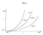
- An example of the objective-function O will be described later by referring to Fig. 4.
- a step Z0-4 it is determined whether the index variable A is less than a base-station location candidate point number N, and if A ⁇ N, in a step Z0-5, then the steps subsequent to the step Z0-2 are repeated after 1 (one) is added to A. If A ⁇ N in a step Z0-4, then the process proceeds to a step Z0-6.
- the objective-function of which the value becomes maximum is to be selected from among all recorded ones to decide to locate the base station at the base-station arrangement location candidate point having the index number of the above objective-function, and the channel number of the above objective-function is allocated for the above base station.
- the radio-wave propagation characteristic is estimated in the entire service area to record it.
- the second radio-wave propagation characteristic estimation technique is employed for estimating the radio-wave propagation characteristic.
- the high-precision radio-wave propagation characteristic analytic technique such as the ray tracing corresponds hereto.
- An estimation result is recorded in a memory, a disk, etc.
- a step Z0-8 by making a reference to the estimation result of the radio-wave propagation characteristic computed and stored by the second radio-wave propagation characteristic estimation technique, which is related to all base stations for which installment was decided thus far, the transmitted power of each base station, and the area (cell) that each base station covers are found to compute the traffic coverage ratio Rc.
- a cell is defined as a group of minute areas into which the service area is divided. Those minute areas belong to the cell covered by a base station when the minute areas have the minimum propagation loss and desired received quality for the base station.
- the size/shape of each cell varies with not only the radio-wave propagation characteristic, but also the setting of the transmitted power and a received threshold of each station.
- the so-called received threshold herein is a threshold in performing a demodulation processing in a receiver, and the demodulation is performed only when the received signal satisfies the above threshold.
- the received threshold is known as a CSMA threshold, a receiver threshold, etc. in a carrier sense multiple access (CSMA) technique that has been put to practical use in the wireless LAN, etc. It is necessary to set the transmitted power of the base station, and (or) the received threshold as well simultaneously in finding the covered area of each base station. The larger the transmitted power is, and the lower the received threshold is, the larger cell spreads, which leads to an increase in the traffic that occurs within the cell.
- the traffic quantity inside the cell is set to be less than the maximum traffic quantity that can be processed in one base station.
- the transmission power and the received threshold there is the range thereof in which respective values can be set, whereby regulation is made within the respective setting ranges in operating both parameters.
- the channel allocation for the base station of which installment was newly decided also can be rechecked.
- the reason is that the channel reallocation by employing the more precise propagation characteristic by the second propagation characteristic estimation technique can provide more interference tolerance.
- the channel allocation for which installment was newly decided was employed by the first propagation estimation technique.
- the re-checking processing of the channel allocation is performed as follow. At first, the objective-function is re-computed on the supposition that the newly installed base station used each channel according to the propagation characteristic estimated by the second propagation characteristic estimation technique. The channel of which the objective-function becomes maximum is used among respective channels.
- a rate of a total traffic to be absorbed by the base station group for which installment was decided to a total traffic quantity that occurs within the entire service area is found to specify this as a traffic coverage ratio Rc.
- a step Z0-9 the traffic coverage ratio Rc is compared with a required traffic coverage ratio Rth, if Rc ⁇ Rth, then the processing returns to the step Z0-1, and if Rc > Rth is satisfied, then the base-station installment processing is completed (a step Z0-10).
- the first embodiment of the present invention explained by use of Fig. 2 is characterized in sequentially adding the base stations one by one. Taking the traffic quantity into consideration in the stage of adding the base station enables the appropriate base-station cell design that responded to roughness/fineness of the traffic quantity, thus allowing the propagation quality to be prevented from deteriorating due to congestion. Also, the cell design having high tolerance against the interference is achieved possible because the cell design, which took the interference quantity into consideration, is made with the second radio-wave propagation characteristic estimation such as the ray tracing forecasted in high precision.
- the second radio-wave propagation characteristic estimation evaluation which is of high precision but requires a lot of the calculation amount, is made after the base-station arrangement location was decided, and the first radio-wave propagation characteristic estimation technique of which the calculation amount is few is employed at the time of the additional base-station search processing.
- the high-precision radio-wave propagation characteristic evaluation extending over the entire service area should be executed only for the base station to be installed finally, which enables a reduction in the time required for the base-station arrangement design, as compared with the technique of the non-patent document 1 that requires the high-precision radio-wave propagation characteristic evaluation extending over the entire service area for all base-station candidate points.
- the present invention enables the cell design having always a constant effect without a help of the experience/perception of design experts.
- the effect such that a drastic reduction in the design processing time is achieved.
- Fig. 4 is a view illustrating one example of the objective-function O with the traffic absorption quantity T and the quality value Q taken as an argument. The setting is made so that the higher the traffic absorption quantity T is, and the higher the quality value Q is, the larger the objective-function becomes.
- Introduction of the objective-function shown in Fig. 4 allows two evaluation indexes of the traffic absorption quantity and the quality value to be integrated for handling at the time of the base-station cell design.
- * represents multiplication in each above-mentioned equation.
- the objective-function O is further multiplied by the installment priority P (or the installment priority P is added after weighting) to employ this as an objective-function.
- the objective-function O has an identical value, even though A (location candidate point), and k (channel) thereof are different respectively. This could happen because the traffic absorption quantity of each base station is limited to the maximum traffic that the base station can accommodate.
- a different objective-function O' (T', Q') is sometimes employed. For example, not by taking the maximum traffic that AP can accommodate into consideration in T' in the objective-function O', O' different from the objective-function O can be employed as a secondary judgment stuff.
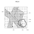
- Fig. 5 is a view explaining the situation where the objective-function O is decided in the present invention in a model-type manner.
- a service area Z1-1 is given, and the traffic distribution is given like domains Z1-7 and Z1-8 shown with oblique lines within the service area Z1-1.
- the domains Z1-7 and Z1-8 differ in a traffic occurrence density.
- a black small circle Z1-9 indicates the base-station location candidate point, black squares Z1-4 to Z1-6 indicate the already-installed base stations, or the base station for which installment was decided in the step Z0-6 of Fig. 2 by employing a method relating to the present invention.
- a white square Z1-2 indicates the base-station candidate installed at a certain location candidate point, and how the objective-function O can be found for the base-station candidate will be explained below.
- a cell Z1-3 that the above base-station candidate Z1-2 forms is specified.
- the shape of the cell Z1-3 can be found in the step Z0-2 of Fig. 2.
- the transmitted power is decided as follows. That is, the transmitted power is the transmitted power regulated so that the traffic quantity that occurs within the cell becomes the maximum traffic quantity that one base station can process, or the maximum transmitted power, whichever is lower.
- the following can be considered. At first, suppose the cell at the time that the transmission power was maximized to calculate the traffic quantity to be absorbed within the above cell, if this calculated traffic quantity is fewer than the maximum traffic quantity that one base station can process, to assume that the transmitted power is the maximum power of this base station, and to assume that the cell is the above-mentioned calculated cell. Also, when the above calculated traffic quantity is larger than the maximum traffic quantity that one base station can process, assume the transmission power, which is enough to cover the cell that absorbs the traffic that corresponds to this maximum traffic quantity, to be a transmitted power of this base station.
- the traffic absorption quantity T is equivalent to a total quantity of the traffic that occurs inside the cell Z1-3. That is, it is the traffic quantity that occurs in respective portions of the domains Z1-7 and Z1-8 to be included inside the cell Z1-3.
- the quality value Q which is given as a function of the total sum of the interference quantities from the already-installed base stations Z1-4 to Z1-6 that are received in the location candidate Z1-2, is defined so that the lower the total sum of the interference quantities is, the higher it becomes.
- the quality value Q is defined so as to be inversely proportional to the total sum of the interference quantity.
- the interference quantity from each of the already-installed base stations Z1-4 to Z1-6 is decided by those interference transmission power and the propagation loss up to the location candidate.
- the interference-wave transmitted power there are a case where the fixed value is employed for it, and a case where it is set in proportional to the size of the traffic to be loaded on the above already-installed base station.
- the result of the high-precision propagation-loss estimation computed and stored by said second radio-wave propagation characteristic estimation technique is applied for the propagation loss from each above already-installed base station up to the location candidate point.
- the base-station cell design becomes possible that took into consideration the traffic quantity that occurs within the cell to be formed by the base-station candidate, and the interference quantity that is received in the above base station.
- This embodiment is characterized in that, in the event that the base station is installed at the base-station location candidate point, the base-station installment is made more preferentially for the installment location in which the traffic quantity is processed the more by the above base station, or the less the interference quantity is.
- Fig. 6 is a view illustrating an additional embodiment relating to the specification of the traffic absorption quantity T in Fig. 5.
- Z2-1, Z2-4, and Z2-5 indicate the already-installed base stations, or the base station for which installment was decided in the step Z0-6 of Fig. 2 employing a method relating to the method of the present invention, respectively, and Z2-9 indicates the base-station candidate.
- the cells to be formed by the already-installed base stations of Z2-1, Z2-4, and Z2-5 are Z2-2, Z2-3, and Z2-6 respectively, and the cell to be formed by the base-station candidate Z2-9 is Z2-10.
- the so-called base-station selection for each minute area indicates an action of, in the event that a terminal was assumed to exist in a certain minute area, connecting to the base station satisfying a desired received quality, and having the minimum propagation loss, or an action of connecting to the base station satisfying a desired received quality that can realize communication of which the received quality or the received signal power is high. That is, the above base-station selection is made, thereby allowing formation of a cell boundary such that the best communication quality can be assured in each location within the service area.
- each minute area does not select the base-station candidate Z2-9 at the time of selecting the base station, and the cell boundary of the base-station candidate Z2-9 assumes a fixed shape, or a shape like Z2-10 to be found by said first radio-wave propagation characteristic estimation technique.
- the traffic that occurs within the cell formed in such a manner is to be absorbed by the base station that takes charge of the above cell.
- the limit value is set at the traffic quantity that one base station can accommodate, and the traffic quantity that occurs within the cell found above, or the allowable traffic quantity of the base station, whichever is lower, can be assumed to be the traffic quantity to be accommodated in the above cell.
- An additional embodiment relating to the specification of the traffic absorption quantity T shown in Fig. 6 is characterized in, at the time of calculating the traffic absorption quantity T for a cell Z2-10, excluding the traffic that occurs in the domains Z2-7, and Z2-8 that the already-installed base stations Z2-4 and Z2-5 have already covered. Excluding the traffic already absorbed by the already-installed base stations from the traffic quantity T to be loaded on the base station that is newly added allows more correct traffic quantity T to be estimated.
- Fig. 7 indicates a further embodiment relating to the specification of the traffic absorption quantity T.
- Z6-1, Z6-4, and Z6-5 indicate the already-installed base stations, or the base station for which installment was decided in the step Z0-6 of Fig. 2 by employing a method relating to the method of the present invention, respectively, and Z6-9 indicates the base-station candidate.
- the cells to be formed by the already-installed base stations Z6-1, Z6-4, and Z6-5 are Z6-2, Z6-3, and Z6-6 respectively, and the cell to be formed by the base-station candidate Z6-9 is Z6-10.
- the result of the high-precision propagation-loss estimation computed and stored by said second radio-wave propagation characteristic estimation technique (Z0-7 of Fig. 2) is applied.
- the cell to be formed by the base-station candidate Z6-9 is found by employing the result of the propagation characteristic estimation to be computed by said first radio-wave propagation characteristic estimation technique. It is supposed that the appropriate base-station selection is employed in each of minute area within the service area.
- the so-called base-station selection for each minute area indicates an action of, in the event that a terminal was assumed to exist in a certain minute area, connecting to the base station satisfying a desired received quality and having the minimum propagation loss, or an action of connecting to the base station satisfying a desired received quality that can realize communication of which the received quality or the received signal power is high. That is, the above base-station selection is employed, thereby allowing formation of a cell boundary such that the best communication quality can be assured in each location within the service area.
- the traffic that occurs within the cell formed in such a manner is to be absorbed by the base station that takes charge of the above cell.
- the limit value is set at the traffic quantity that one base station can accommodate, and the traffic quantity that occurs within the cell found above, or the allowable traffic quantity of the base station, whichever is lower, can be assumed to be the traffic quantity to be accommodated in the above cell.
- a further embodiment relating to the specification of the traffic absorption quantity T shown in Fig. 7 is characterized in assuming a total quantity of the traffic to be absorbed by the already-installed base stations Z6-1, Z6-4, and Z6-5, and the base-station candidate Z6-9 to be the traffic absorption quantity T.
- the traffic absorption quantity T is defined as a total quantity of the traffic to be absorbed by the already-installed base stations and the base-station candidate within the service area. Hence, a base station candidate that can absorb maximum traffic quantity accompanied with already installed base stations is selected to be newly added.
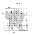
- Fig. 8 is a view illustrating an additional embodiment relating to the specification of the quality value Q in Fig. 5 in a model-type manner.
- an evaluation terminal Z3-6 indicated with a white triangle, which connects to a base-station candidate Z3-5 indicated with a white square, to specify the quality value Q with a ratio of the desired received signal power and the undesired received signal power (DU ratio) to be observed in the above evaluation terminal Z3-6.
- the propagation loss to be computed by said first radio-wave propagation characteristic estimation technique is employed in computing the desired signal power.
- a linear distance Z3-10 from the base-station candidate Z3-5 up to the evaluation terminal Z3-6 is employed as a distance.
- Z3-1 to Z3-3 indicate the already-installed base stations, or the base station for which installment was decided in the step Z0-6 of Fig. 2 by employing a method relating to the method of the present invention, respectively.
- the undesired signal power is decided by the propagation loss from each of the base stations Z3-1 to Z3-3 up to the evaluation terminal Z3-6, and the undesired signal transmission power that each already-installed base station emits.
- the undesired signal transmission power to be emitted from each of the already-installed base stations Z3-1 to Z3-3 there are a case where it is assumed to be fixed, and a case where it is decided responding to the traffic quantity to be loaded on each already-installed base station.
- the high-precision propagation-loss value estimated and stored by said second radio-wave propagation characteristic estimation technique is employed for the propagation loss from each already-installed base station up to the evaluation terminal.
- Said evaluation terminal Z3-6 is assumed to be in each location within the cell Z3-4 that said base-station candidate Z3-5 forms to find said DU ratio, and the quality value Q is specified by averaging it.
- the location within the above cell Z3-4 in which no traffic occurs is not assumed to be an object of the averaging processing.
- a weighting is made responding to the size of the traffic density within the above cell Z3-4 for averaging it.
- Fig. 9 is a view illustrating a further embodiment relating to the specification of the quality value Q in Fig. 5 in a model-type manner.
- the entire region within the service area is scanned with an evaluation terminal Z4-4 to find the DU ratio in each evaluation-terminal arrangement location, and to specify a ratio satisfying a desired DU ratio as the quality value Q.
- the evaluation terminal is connected to the already-installed base station, or the base-station candidate that can make communicate with the highest receiving signal power from the location in which the above terminal was installed, and that the interference signal power is the total sum of the undesired signal powers from the already-installed base stations and the base station candidate other than the base station assumed to connect to the above terminal.
- the above quality value is defined so that the smaller this total sum is, the higher the quality value becomes.
- an evaluation terminal Z4-4 connects to an already-installed base station Z4-2, thus the interference signals arrive at the evaluation terminal Z4-4 from already-installed base stations Z4-1 and Z4-3, and a base-station candidate Z4-5.
- a location within the service area in which no traffic occurs is not assumed to be an object of evaluation for measuring the quality value Q.
- the quality value Q is specified by performing weighted addition of the DU ratio responding to the size of the traffic density within the service area.
- the propagation loss from the base-station candidate to the evaluation terminal is given with the propagation loss to be computed by said first radio-wave propagation characteristic estimation technique.
- the propagation loss value between the already-installed base station and the evaluation terminal is estimated and stored by said second radio-wave propagation characteristic estimation technique.
- the base-station cell design achieves that, in adding the base station candidate, took into consideration not only the quality value to be observed within the base-station candidate, but also an influence of the quality deterioration to be observed in the other cells due to addition of the above base-station candidate.
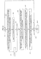
- Fig. 10 is a view illustrating a cell design apparatus D001 for realizing an operational flow shown in Fig. 2 as a schematic functional block.
- input information 1 are listed map information, traffic distribution information, base-station installment candidate point information, and the required traffic coverage ratio Rth (see the step Z0-9 of Fig. 2) of the service area.
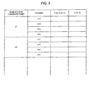
- An objective-function O measurement record section 2 calculates the traffic absorption quantity T and the quality value Q, employing a first radio-wave propagation estimation engine 3 for executing the foregoing first radio-wave propagation estimation technique, calculates the objective-function O responding to these T and Q, and records it in a memory section (particularly, not shown in the figure) in such a manner as shown in Fig. 3.
- a base-station installment/radio-wave propagation characteristic evaluation section 4 decides to install the base station at the base-station location candidate point having the maximum objective-function O obtained, employs a second radio-wave propagation estimation engine 5 for executing the foregoing second radio-wave propagation estimation technique, estimates the radio-wave propagation characteristic within the service area with the base station for which installment was newly decided taken as a transmission point, and records it in the memory section.
- a traffic coverage ratio evaluation section 6 finds the transmission power of each base station and the area that each base station covers, and calculates the traffic coverage ratio Rc.
- a cell design finish determination section 7 determines whether the traffic coverage ratio Rc exceeds a required traffic coverage ratio Rth, and when it exceeded, makes determination as to the cell design finish. And, the parameter setting result such as the base-station arrangement result, the channel, and the transmission power is output as output information 8.
- Fig. 11 is a flowchart illustrating a second embodiment in the base-station cell design algorithm of the present invention.
- This second embodiment is characterized in being performed continuously after the processing described in the first embodiment of Fig. 2.
- a step Z5-1 indicates the entire processing of the first embodiment described in Fig. 2.
- a modified traffic coverage ratio Rm that is a traffic coverage ratio in a case where each of the already-installed base station was deleted is calculated to find a difference between the traffic coverage ratio Rc of final result from the first embodiment of Fig. 2 and Rm, and to find a base station D of which Rc - Rm is minimum.
- Rm is found by employing the estimation result found in Z0-7 of Fig. 2 by employing the second radio-wave propagation estimation technique.
- Rm can be calculated as follows. First, an already-installed base station is assumed to be deleted. And a rate of a total quantity of the traffic that covered by the rest of all the already-installed base station to a total traffic quantity in the entire service area.
- the objective-function O (T, Q) in a case where each base station was deleted may be computed to select the base station of which the objective-function O is maximum at the time that it was deleted as a deletion candidate base station.
- the traffic coverage ratio Rm in a case where the base station selected based on the objective-function was deleted is computed, and the processing proceeds to the next step.
- a step Z5-3 it is determined whether or not the modified traffic coverage ratio Rm in a case where it was assumed that the base station D was deleted is still more than the threshold Rth of the traffic coverage ratio. If Rm > Rth is satisfied, then the base station D is deleted from the already-installed base station group in a step Z5-4, and if it is not satisfied, then the processing proceeds to a step Z5-6, and the base-station cell design is finished.
- step Z5-4 After the base station D was deleted in the step Z5-4, the transmission power of each base station and the area covered by each base station are found once again in a step Z5-5 to re-compute the traffic coverage Rc.
- the detailed processing in the step Z5-5 is identical to the processing of the step Z0-8 in the first embodiment described in Fig. 2. After the step Z5-4 was finished, the steps subsequent to Z5-2 are repeated once again.
- the second embodiment of the present invention explained in Fig. 11 allows the useless base station to be deleted out of the base stations installed in the first embodiment.
- the first embodiment described in Fig. 2 there is the possibility of the occurrence of the base station that results in being uselessly installed due to employing the first radio-wave propagation characteristic estimation technique, which needs a small amount of calculations while having low estimation precision, that is, the base station that does not contribute to an improvement in the traffic coverage ratio so much.
- the second embodiment allows the base station arrangement having a least sufficient number to be realized, by deleting such a useless base station.
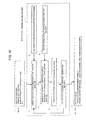
- Fig. 12 is a view illustrating a cell design apparatus D002 for realizing an operational flow shown in Fig. 11 as a schematic functional block, and the identical portions to Fig. 10 are indicated with identical numerals.
- the cell design apparatus D002 is connected to the rear stage of the cell design apparatus D001 shown in Fig. 10 for operation, and deletion base-station decision section 9 receives the output of the cell design apparatus D001 of Fig. 10, and decides which base station should be deleted.
- This technique of the deletion base-station decision is the processing of the step Z5-2 to Z5-5 in a flow of Fig. 11.
- a cell design finish determination section 10 determines the finish of deletion base-station decision, and also, a base-station deletion section 11 deletes the base station decided in the deletion base-station decision section 9.
- Final output information 8' is obtained in such a manner, and the parameter setting result such as the base-station arrangement result, the channel, and the transmission power is obtained.
- the parameter setting result is made from the output information 8 shown in Fig. 10 by deleting some base stations in the base-station deletion section 11.
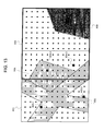
- Fig. 13 is a view illustrating a case where the cell design is made for the area wider than that of Fig. 5 etc.
- the design area shown in Fig. 13 is divided into two areas X01 and X02 that are overlapped with each other.
- the cell design is executed for the area X01 by the cell design technique of the present invention mentioned above.
- the area X02 is designed.
- the area X02 shown with a bold frame is overlapped with the area X01 shown with a fine frame, and base stations X03-4, and X03-3 designed already in the X01 are included in the area X02.
- the base stations X03-3 and X03-4 are considered as the already-installed base station to make the cell design for the location candidate point other than the above base-station installment location according to the foregoing cell design procedure.
- the cell design has to be made for an enormous number of the base-station location candidates, whereby it is anticipated that the memory and the necessary computation quantity becomes enormous.
- extracting a plurality of the areas divided into small pieces allows the reduction of the quantity of the memory and the computation to be achieved.
- the cell design which took the interference from the already-installed base station into consideration, becomes possible in a area B neighboring A.
- the base station was already installed as a matter of fact in the service area taken as an object, if the foregoing cell design in accordance with the present invention is made upon presetting the location information, setting channel information, transmission power information, etc. of the above base station, the design of the new-addition base station after due consideration of these interferences becomes possible.
- the communication quality value Q (A, k) was defined as a function of a location A in which the base station was installed, and a channel k to be used; however, as Q (A, k, t, d), a type of an antenna t and an installation direction d of the base station have to be added as an element.
- the processing flow will be explained in a case where the communication quality value is assumed to be Q (A, k, t, d), based on Fig. 2.
- the quality value Q is computed for all combinations of the base-station location candidate point A, the channel k, the type of the antenna t, and the installment direction d.
- the objective-function to be computed in the step Z0-3 amounts to O (t (A), Q (A, k, t, d)), and the contents recorded in the memory are ones shown in Fig. 14.
- T (A), Q (A, k, t, d), and O (T (A), Q (A, k, t, d)) are to be recorded respectively responding to the channel k, the type of the antenna t, and the installation direction d at each base-station candidate point indicated with the index number A (shown as A1, A2, ...) respectively.
- the number of installation direction depends on the sharpness of antenna directivity. For example, in the event of the non-directional antenna, the pattern thereof is only one (1) because it does not make sense to cause the installation direction to vary.
- the installment-location candidate point at which the maximum objective-function is obtained, the channel, the type of the antenna, and the installation direction are set for the above base station.
- the type of the antenna and the installation direction in the event that the type of the antenna and the installation direction were added as an element of the quality value Q, the type of the antenna and the installation direction also are simultaneously output as the output information 8 and 8' in addition to the base-station arrangement result, the channel, the transmission power, etc.
- the processing program for executing the present invention can be modified to a parallel-computable form.
- the computation time can be reduced because the computation can be performed simultaneously by employing plural computers.
- the result obtained by each computer is collected to continue the processing.
- the processing item in the steps Z0-1 to Z0-5 in Fig. 2 where the first radio-wave propagation characteristic estimation technique is employed to search for the parameters for obtaining the maximum objective-function can be executed effective by parallel computing.
- This propagation characteristic computation employing the first radio-wave propagation estimation technique with all base-station location candidate points taken as a transmission point can be performed in the parallel processing because the propagation characteristic can be computed independently at each base-station location candidate point. Also, as to the computation of the objective-function, it can be performed in a parallel processing because the objective-function can be computed independently for each installment condition.
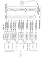
- the technique of the parallel processing will be described in details.
- the subject number for finding the propagation characteristic numbers an occurrence point number N of the traffic and a base-station installment-location candidate point number M.
- N*M kinds of the propagation characteristics that should be found ranging from a propagation characteristic 11 to a propagation characteristic NM (* signifies multiplication).
- P a parallel-processable computer number
- N*M/P portion of the propagation characteristic By connecting the results obtained by respective computers, all the result of propagation characteristics 11 to NM can be obtained. So as to connect the result of the parallel processing, an overhead for communication is required, whereby ⁇ is added to the computation time in the figure.
- a method can be employed of dividing the object that requires the computation into smaller units (at least every one propagation characteristic) for each computer, at the stage that the result for small unit was obtained, to sequentially process the other unit that has not been computed yet (see Fig. 16).
- the objective-function calculation for each installment parameter has to be performed by the pattern number of the installment-location candidate point number (M) x the channel number (C) x the kind number of the antenna (T) x the installment direction number (D). So as to perform this calculation at a high speed, similarly to the foregoing, the parallel processing by the computer is performed. All pattern numbers amount to M*C*A*D, whereby in the event of employing the computer group having an identical processing capability (computer number P), M*C*A*D/P of the processing is allocated for each computer for computation. In the event of using the computers having different processing capabilities, the processing is performed similarly to Fig. 16.
- the estimation employing the first propagation characteristic estimation technique and by performing the calculation of the objective-function in the parallel processing, the reduction of the computation time can be realized.
- the present invention also can be used for deciding the channel, the transmission electric power, the type of the antenna, the installation direction etc. for the base station preinstalled actually.
- This can be realized by designating the layout of the already-installed base station as a base-station location candidate point to assume that the determination criteria of the step Z0-9 in Fig. 2 is not the traffic coverage ratio, but the completion of the installation for all base-station location candidate points.
- it is possible to design the channel, the transmission power, the type of the antenna, and the installation direction at each base station so that they have the appropriate values respectively.
- the service area was explained as a two-dimensional one; however this is an example for facilitating the grasp of the contents, and the three-dimensional space is similarly applicable for it.
- the configuration can be made so that a flow of each operational processing mentioned above is pre-filed in the record medium as a program to cause the computer to read this for execution.
- the design method of the present invention does not need the perception and the experience of a human being because the method can make quantitative judgment by defining and using the objective-function of which the argument is at least one of the traffic absorption quantity and the communication quality value to add the base station.
- the effect exists of reducing the quantity of the radio-wave analysis processing that accounts for a majority of the cell design processing, and of enabling the fast base-station cell design.
- the invention employs a technique of which the calculation amount is few for the radio-wave propagation characteristic evaluation to be used in selecting the base station that should be added from all of the base-station candidates and employs a technique of which the calculation amount is much, but provides high precision for the radio-wave propagation characteristic evaluation to be made after the selection and put the result of the high-precision radio-wave propagation characteristic evaluation to be made for estimating the interference quantity in selecting the arrangement location of the base station to be added subsequently.
- deleting the base stations sequentially that do not contribute to an increase in the traffic coverage ratio from the above-mentioned additional base-station group allows the base-station arrangement having a least sufficient number to be realized. And as it is not necessary to make a new radio-wave analysis for this already-installed base-station group, in sequentially deleting the base stations because the high-precision radio-wave analysis has been completed in the entire service area with each already-installed base station taken as a transmission point, the design by the present invention can be performed at a high speed.
Landscapes
- Engineering & Computer Science (AREA)
- Computer Networks & Wireless Communication (AREA)
- Signal Processing (AREA)
- Mobile Radio Communication Systems (AREA)
Applications Claiming Priority (3)
| Application Number | Priority Date | Filing Date | Title |
|---|---|---|---|
| JP2002307732 | 2002-10-23 | ||
| JP2003158759A JP4819303B2 (ja) | 2002-10-23 | 2003-06-04 | 移動通信システムにおける基地局設置設計方法及び基地局設置設計装置並びにプログラム |
| EP20030023957 EP1414257A1 (de) | 2002-10-23 | 2003-10-22 | Verfahren, Einrichtung und Programm zum Entwurf einer Basisstationszelle in einem mobilen Kommunikationssystem |
Related Parent Applications (1)
| Application Number | Title | Priority Date | Filing Date |
|---|---|---|---|
| EP20030023957 Division EP1414257A1 (de) | 2002-10-23 | 2003-10-22 | Verfahren, Einrichtung und Programm zum Entwurf einer Basisstationszelle in einem mobilen Kommunikationssystem |
Publications (2)
| Publication Number | Publication Date |
|---|---|
| EP1879413A2 true EP1879413A2 (de) | 2008-01-16 |
| EP1879413A3 EP1879413A3 (de) | 2008-08-13 |
Family
ID=32072529
Family Applications (2)
| Application Number | Title | Priority Date | Filing Date |
|---|---|---|---|
| EP07119636A Withdrawn EP1879413A3 (de) | 2002-10-23 | 2003-10-22 | Verfahren und Vorrichtung für den Entwurf einer Basisstationszelle sowie Programm davon in einem mobilen Kommunikationssystem |
| EP20030023957 Withdrawn EP1414257A1 (de) | 2002-10-23 | 2003-10-22 | Verfahren, Einrichtung und Programm zum Entwurf einer Basisstationszelle in einem mobilen Kommunikationssystem |
Family Applications After (1)
| Application Number | Title | Priority Date | Filing Date |
|---|---|---|---|
| EP20030023957 Withdrawn EP1414257A1 (de) | 2002-10-23 | 2003-10-22 | Verfahren, Einrichtung und Programm zum Entwurf einer Basisstationszelle in einem mobilen Kommunikationssystem |
Country Status (4)
| Country | Link |
|---|---|
| US (2) | US7079844B2 (de) |
| EP (2) | EP1879413A3 (de) |
| JP (1) | JP4819303B2 (de) |
| CN (1) | CN1498000B (de) |
Families Citing this family (66)
| Publication number | Priority date | Publication date | Assignee | Title |
|---|---|---|---|---|
| US7505048B2 (en) * | 2003-04-25 | 2009-03-17 | Microsoft Corporation | Estimation of overlap of polygons |
| WO2005046276A1 (en) * | 2003-11-07 | 2005-05-19 | Telecom Italia S.P.A. | Method, system and computer program product for determining the cell area of a base station by taking into account pixel of territory specific quantity of traffic, and network planned using this method |
| EP1719374B1 (de) * | 2004-02-27 | 2008-07-09 | Telecom Italia S.p.A. | Standortauswahl für funkstationen in einem telekommunikationsnetzwerk |
| JP4711117B2 (ja) * | 2005-04-19 | 2011-06-29 | 日本電気株式会社 | 探索方法および探索システムと探索プログラム |
| DE102005020440A1 (de) * | 2005-04-29 | 2006-11-09 | Glasbau Hahn Gmbh + Co. Kg | Vitrine zur Aufbewahrung und/oder Zurschaustellung von Gegenständen |
| JP4655836B2 (ja) * | 2005-09-06 | 2011-03-23 | Kddi株式会社 | 鉄道線路に基地局を最適配置するためのセル設計プログラム及び装置 |
| JP4946867B2 (ja) * | 2005-11-22 | 2012-06-06 | 日本電気株式会社 | 無線ネットワーク設計装置および方法 |
| CN100563366C (zh) * | 2005-12-02 | 2009-11-25 | 上海交通大学 | 无线通信系统中下行链路的分配方法及装置 |
| US8265635B2 (en) * | 2005-12-09 | 2012-09-11 | Nec Corporation | Method for determining positioning accuracy based on origination and receiving terminals and positioning device and program therefor |
| CN1992967B (zh) * | 2005-12-29 | 2010-05-05 | 京移通信设计院有限公司 | 一种码分多址无线网络候选基站位置的优选方法 |
| US7613466B2 (en) * | 2006-03-23 | 2009-11-03 | Media Technology Ventures, Inc. | Systems and methods for evaluating changes in transmissions for a point of communication |
| KR100959331B1 (ko) * | 2006-10-13 | 2010-05-20 | 삼성전자주식회사 | 광대역 무선통신 시스템에서 세그먼트 할당 장치 및 방법 |
| GB2447439B (en) | 2007-02-02 | 2012-01-25 | Ubiquisys Ltd | Access point power control |
| US8000281B2 (en) * | 2007-08-09 | 2011-08-16 | Industrial Technology Research Institute | System and method for providing multicast/broadcast services in a wireless network |
| KR101348033B1 (ko) * | 2007-09-21 | 2014-01-03 | 주식회사 케이티 | 기지국 관리 시스템에서 이기종 기지국 시스템 간의 간섭분석 방법 |
| JPWO2009075246A1 (ja) * | 2007-12-12 | 2011-04-28 | 日本電気株式会社 | 無線アクセス網管理装置、設備計画支援システム及びそれらに用いる設備計画支援方法 |
| WO2009119545A1 (ja) * | 2008-03-24 | 2009-10-01 | 日本電気株式会社 | 基地局配置設計支援システム、基地局配置設計支援方法及びプログラム |
| JP5509666B2 (ja) * | 2008-05-08 | 2014-06-04 | 日本電気株式会社 | 電波伝搬特性推測支援システム、電波伝搬特性推測支援方法及び電波伝搬特性推測支援装置 |
| JP5522054B2 (ja) * | 2008-12-09 | 2014-06-18 | 日本電気株式会社 | 電波環境データ補正システム、方法およびプログラム |
| KR101170875B1 (ko) * | 2008-12-19 | 2012-08-02 | 한국전자통신연구원 | 스펙트럼 자유화를 위한 무선 서비스 용도 변경 판정 방법 및 장치 |
| JP5139462B2 (ja) * | 2009-03-16 | 2013-02-06 | アクティックス・ゲゼルシャフト・ミト・べシュレンクテル・ハフツング | セルラー無線ネットワーク内におけるマルチアンテナの配備によって得られる容量および有効範囲の利得を近似し最適化する方法 |
| US8638679B2 (en) | 2009-05-28 | 2014-01-28 | Qualcomm Incorporated | Method and apparatus that facilitates automatic assistance for positioning of access point base stations |
| GB2471681B (en) | 2009-07-07 | 2011-11-02 | Ubiquisys Ltd | Interference mitigation in a femtocell access point |
| GB2472597B (en) | 2009-08-11 | 2012-05-16 | Ubiquisys Ltd | Power setting |
| US9622169B2 (en) * | 2010-01-04 | 2017-04-11 | Nec Corporation | Power-save operation supporting apparatus, power-save operation supporting method, storage medium and base station |
| US20110208668A1 (en) | 2010-02-22 | 2011-08-25 | Google Inc. | Server Provider Recommendation Engine |
| JP5356281B2 (ja) * | 2010-02-25 | 2013-12-04 | ソフトバンクモバイル株式会社 | 通信品質推定システム、プログラム、および推定品質推定方法 |
| US8433327B2 (en) * | 2010-05-19 | 2013-04-30 | Alcatel Lucent | Methods of determining coverage areas |
| WO2012011147A1 (ja) * | 2010-07-21 | 2012-01-26 | ソフトバンクBb株式会社 | 通信特性解析システム、通信特性解析方法、及び通信特性解析プログラム |
| US9042931B2 (en) | 2010-09-08 | 2015-05-26 | Telcordia Technologies, Inc. | Distributed power level selection method and system for cellular wireless networks under joint constraints |
| JP5618363B2 (ja) * | 2010-10-14 | 2014-11-05 | 日本電気株式会社 | 移動通信システムの管理システム及び方法と装置 |
| US8630652B2 (en) * | 2010-10-29 | 2014-01-14 | Alcatel Lucent | Method and apparatus for optimizing the location of heterogeneous underlaid evolved node-Bs |
| JP5665031B2 (ja) * | 2011-02-25 | 2015-02-04 | Kddi株式会社 | 無線基地局パラメータ算出装置、無線基地局パラメータ算出方法、及びコンピュータプログラム |
| US9137733B2 (en) * | 2011-03-15 | 2015-09-15 | At&T Mobility Ii Llc | Dynamic control of cell reselection parameters |
| JP5538286B2 (ja) * | 2011-03-29 | 2014-07-02 | Kddi株式会社 | 位置検出装置及び位置検出プログラム |
| JP5456735B2 (ja) * | 2011-08-26 | 2014-04-02 | 日本電信電話株式会社 | 置局設計方法、置局設計プログラムおよび置局設計装置 |
| JP2014017587A (ja) * | 2012-07-06 | 2014-01-30 | Fujitsu Ltd | 無線通信ネットワークエリア設計方法、コンピュータプログラム及び無線通信ネットワークエリア設計装置 |
| US8938245B2 (en) | 2012-07-30 | 2015-01-20 | Qualcomm Incorporated | Wireless transmitter identity or positioning information partitioning |
| US9210600B1 (en) * | 2012-09-07 | 2015-12-08 | Sprint Communications Company L.P. | Wireless network performance analysis system and method |
| CN102932803B (zh) * | 2012-10-22 | 2015-04-01 | 华为技术有限公司 | 自动布放无线接入装置的方法和设备 |
| US9432865B1 (en) | 2013-12-19 | 2016-08-30 | Sprint Communications Company L.P. | Wireless cell tower performance analysis system and method |
| US10123223B1 (en) | 2014-01-30 | 2018-11-06 | Sprint Communications Company L.P. | System and method for evaluating operational integrity of a radio access network |
| CN103957554B (zh) * | 2014-04-21 | 2017-08-04 | 南开大学 | 一种无线基站小区覆盖率和容量的检测评估方法 |
| JP6330471B2 (ja) * | 2014-05-16 | 2018-05-30 | 株式会社デンソー | 無線測位装置 |
| CN105592470B (zh) * | 2014-10-24 | 2019-03-22 | 普天信息技术有限公司 | 一种自动布站方法和装置 |
| KR101696318B1 (ko) * | 2015-01-16 | 2017-01-23 | 주식회사 엘지유플러스 | 무선 망 관리 투자 방법 및 장치 |
| JP6376281B2 (ja) | 2015-03-20 | 2018-08-22 | 日本電気株式会社 | サイト位置優先順位決定装置及び方法 |
| CN107786986B (zh) * | 2016-08-30 | 2020-02-11 | 新华三技术有限公司 | Ap放置方法及装置 |
| KR102661600B1 (ko) * | 2016-11-17 | 2024-04-30 | 삼성전자 주식회사 | 실재 환경관련 정보를 고려한 통신 채널 분석과 무선 망 설계 방법 및 장치 |
| US10820213B2 (en) | 2016-11-17 | 2020-10-27 | Samsung Electronics Co., Ltd. | Method and apparatus for analyzing communication environment based on property information of an object |
| US10887029B2 (en) | 2016-11-17 | 2021-01-05 | Samsung Electronics Co., Ltd. | Method and apparatus for analysing communication channel in consideration of material and contours of objects |
| KR102586208B1 (ko) | 2016-11-17 | 2023-10-10 | 삼성전자 주식회사 | 물체의 재질 정보 및 외부 형태 정보를 고려한 통신 채널 분석 방법 및 장치 |
| EP3652977A4 (de) * | 2017-07-12 | 2021-02-24 | Commscope Technologies LLC | Verfahren und system zur hf-planung in einer dynamischen spektrenumgebung |
| KR102340252B1 (ko) | 2017-09-13 | 2021-12-16 | 삼성전자주식회사 | 무선 통신 시스템에서 서비스 가용성을 분석하기 위한 장치 및 방법 |
| KR102371016B1 (ko) * | 2017-09-27 | 2022-03-07 | 삼성전자 주식회사 | 무선 통신 시스템에서 망 설계를 위한 분석 방법 및 장치 |
| JP7260739B2 (ja) * | 2018-11-29 | 2023-04-19 | 富士通株式会社 | 情報処理装置、無線アクセスポイントの配置演算方法、および無線アクセスポイントの配置演算プログラム |
| JP7081555B2 (ja) * | 2019-04-02 | 2022-06-07 | 日本電信電話株式会社 | 置局支援方法および置局支援システム |
| JP7272109B2 (ja) * | 2019-05-23 | 2023-05-12 | 富士通株式会社 | 電波伝搬シミュレーション装置、電波伝搬シミュレーションプログラム及び電波伝搬シミュレーション方法 |
| JP7223236B2 (ja) * | 2019-06-13 | 2023-02-16 | 日本電信電話株式会社 | 置局支援設計装置、置局支援設計方法、及びプログラム |
| WO2021257253A1 (en) | 2020-06-17 | 2021-12-23 | Commscope Technologies Llc | Methods and systems for provisioning of parameter data of radios controlled by a spectrum access system |
| CN114125865B (zh) * | 2020-08-31 | 2023-10-27 | 中国移动通信集团重庆有限公司 | 一种5g基站的规划方法、装置、计算设备和存储介质 |
| US11683090B1 (en) | 2022-01-18 | 2023-06-20 | T-Mobile Usa, Inc. | Laser-based enhancement of signal propagation path for mobile communications |
| WO2023157064A1 (ja) * | 2022-02-15 | 2023-08-24 | 日本電信電話株式会社 | 置局設計装置、置局設計方法、及びプログラム |
| CN115103370B (zh) * | 2022-06-17 | 2024-09-06 | 中国铁建电气化局集团有限公司 | 基于rt在环信道态势估计的ris无线覆盖增强方法 |
| KR102642056B1 (ko) * | 2022-08-22 | 2024-03-04 | 충남대학교산학협력단 | 저복잡도 기지국 배치 방법 및 장치 |
| KR102642057B1 (ko) * | 2022-08-22 | 2024-03-04 | 충남대학교산학협력단 | 정수 선형 계획법 기반 기지국 배치 방법 및 장치 |
Citations (5)
| Publication number | Priority date | Publication date | Assignee | Title |
|---|---|---|---|---|
| EP1098546A2 (de) * | 1999-11-04 | 2001-05-09 | Lucent Technologies Inc. | Verfahren und Vorrichtung zur Ableitungs-basierten Optimierung von drahtloser Netzwerkleistung |
| JP2001285923A (ja) * | 2000-03-31 | 2001-10-12 | Mitsubishi Electric Corp | 基地局配置パターン決定方法 |
| EP1283645A1 (de) * | 2001-08-10 | 2003-02-12 | Societé Française du Radiotéléphone | Planung von Lokalisierungszonen |
| EP1292162A1 (de) * | 2001-09-10 | 2003-03-12 | Koninklijke KPN N.V. | System und Verfahren zur Planung und Auswertung eines Funknetzes |
| EP1351532A1 (de) * | 2002-04-03 | 2003-10-08 | Evolium S.A.S. | Kapazitätsplanung und -optimierung in einem zellularen mobilen Telekommunikationsnetz |
Family Cites Families (29)
| Publication number | Priority date | Publication date | Assignee | Title |
|---|---|---|---|---|
| US5463673A (en) * | 1993-04-29 | 1995-10-31 | Northern Telecom Limited | In-building radio deployment technique for wireless personal communications systems |
| US5365571A (en) * | 1993-05-24 | 1994-11-15 | Hughes Aircraft Company | Cellular system having frequency plan and cell layout with reduced co-channel interference |
| IT1261365B (it) * | 1993-12-02 | 1996-05-20 | Cselt Centro Studi Lab Telecom | Procedimento e dispositivo per il controllo di potenza nella tratta stazione base-mezzo mobile di un sistema radiomobile con accesso a divisione di codice |
| US5623429A (en) * | 1994-04-06 | 1997-04-22 | Lucent Technologies Inc. | Techniques for expeditiously predicting electromagnetic wave propagation |
| JP3365054B2 (ja) * | 1994-06-29 | 2003-01-08 | カシオ計算機株式会社 | 位置情報送信システムおよびそれに用いられる位置情報管理装置 |
| US5475870A (en) * | 1994-09-12 | 1995-12-12 | Qualcomm Incorporated | Apparatus and method for adding and removing a base station from a cellular communications system |
| US5574466A (en) * | 1995-03-31 | 1996-11-12 | Motorola, Inc. | Method for wireless communication system planning |
| FI112303B (fi) * | 1995-05-16 | 2003-11-14 | Nokia Corp | Usealla taajuuskaistalla toimiva matkapuhelinjärjestelmä |
| JPH08317458A (ja) | 1995-05-19 | 1996-11-29 | Sanyo Electric Co Ltd | Phs基地局の設置パターン決定方法 |
| FI101118B (fi) * | 1995-06-29 | 1998-04-15 | Ericsson Telefon Ab L M | Matkapuhelinverkon liikenteenhallinta |
| US5710758A (en) * | 1995-09-29 | 1998-01-20 | Qualcomm Incorporated | Wireless network planning tool |
| US5771461A (en) * | 1996-06-28 | 1998-06-23 | Motorola, Inc. | Method and apparatus for power control of a first channel based on a signal quality of a second channel |
| JPH10191419A (ja) * | 1996-12-27 | 1998-07-21 | Matsushita Electric Ind Co Ltd | 移動局装置 |
| JP3856253B2 (ja) * | 1997-10-16 | 2006-12-13 | ソニー株式会社 | セルラー無線通信システム及び基地局 |
| US6154657A (en) * | 1997-10-21 | 2000-11-28 | Telefonaktiebolaget Lm Ericsson | Smart subdivision of base station candidates for position location accuracy |
| US6289203B1 (en) * | 1998-02-25 | 2001-09-11 | Motorola, Inc. | Method of calculating signal propagation loss and creating a data base therefor |
| KR100312303B1 (ko) * | 1998-06-19 | 2001-12-28 | 윤종용 | 이동통신시스템에서로딩인자를사용하여기지국수결정하는방법 |
| US6377555B1 (en) * | 1998-09-22 | 2002-04-23 | Jhong Sam Lee | Method for determining forward link channel powers for a CDMA cellular or PCS system |
| US6587690B1 (en) * | 1999-02-12 | 2003-07-01 | Lucent Technologies Inc. | Method for allocating downlink electromagnetic power in wireless networks |
| FI19992002A (fi) * | 1999-09-20 | 2001-03-20 | Nokia Networks Oy | Solukkoradioverkossa piirikytkentäisen palvelun laadun mittaus |
| EP1168869B1 (de) * | 2000-02-03 | 2004-10-20 | NTT DoCoMo, Inc. | Kommunikationsgerät und Verfahren zur autonomen Zonenbildung |
| WO2001072071A1 (en) * | 2000-03-21 | 2001-09-27 | Motorola Inc. | Method of defining network cells in a communications network |
| EP1146760A3 (de) * | 2000-04-11 | 2002-05-08 | ScoreBoard, Inc. | Vorrichtung und Verfahren zur adaptiven Kanalzuweisung in einem zellularen Telefonsystem |
| FI110746B (fi) * | 2000-05-31 | 2003-03-14 | Nokia Corp | Telekommunikaatioverkon muodostaminen |
| US6459895B1 (en) * | 2000-09-26 | 2002-10-01 | Neoreach, Inc. | Methods for making a cellular system, transmitting to a mobile user in a cellular system, and evaluating the performance of a cellular system |
| JP3570369B2 (ja) | 2000-10-04 | 2004-09-29 | 日本電気株式会社 | 電波伝搬特性予測における遮蔽物の検出方法及びシステム並びに記録媒体 |
| IT1320733B1 (it) * | 2000-10-27 | 2003-12-10 | Cselt Centro Studi Lab Telecom | Sistema e metodo per la pianificazione di una rete per apparecchiature mobili di telecomunicazioni. |
| US6640089B1 (en) * | 2000-11-13 | 2003-10-28 | Verizon Laboratories Inc. | System and method for adaptively predicting radio wave propagation |
| US7031679B2 (en) * | 2002-03-27 | 2006-04-18 | Arraycomm, Llc | Estimating power on spatial channels |
-
2003
- 2003-06-04 JP JP2003158759A patent/JP4819303B2/ja not_active Expired - Fee Related
- 2003-10-22 EP EP07119636A patent/EP1879413A3/de not_active Withdrawn
- 2003-10-22 US US10/689,727 patent/US7079844B2/en not_active Expired - Fee Related
- 2003-10-22 EP EP20030023957 patent/EP1414257A1/de not_active Withdrawn
- 2003-10-23 CN CN200310101768XA patent/CN1498000B/zh not_active Expired - Fee Related
-
2006
- 2006-02-21 US US11/357,340 patent/US8135421B2/en not_active Expired - Fee Related
Patent Citations (5)
| Publication number | Priority date | Publication date | Assignee | Title |
|---|---|---|---|---|
| EP1098546A2 (de) * | 1999-11-04 | 2001-05-09 | Lucent Technologies Inc. | Verfahren und Vorrichtung zur Ableitungs-basierten Optimierung von drahtloser Netzwerkleistung |
| JP2001285923A (ja) * | 2000-03-31 | 2001-10-12 | Mitsubishi Electric Corp | 基地局配置パターン決定方法 |
| EP1283645A1 (de) * | 2001-08-10 | 2003-02-12 | Societé Française du Radiotéléphone | Planung von Lokalisierungszonen |
| EP1292162A1 (de) * | 2001-09-10 | 2003-03-12 | Koninklijke KPN N.V. | System und Verfahren zur Planung und Auswertung eines Funknetzes |
| EP1351532A1 (de) * | 2002-04-03 | 2003-10-08 | Evolium S.A.S. | Kapazitätsplanung und -optimierung in einem zellularen mobilen Telekommunikationsnetz |
Non-Patent Citations (4)
| Title |
|---|
| AMALDI E ET AL: "UMTS radio planning: optimizing base station configuration" VTC 2002-FALL. 2002 IEEE 56TH. VEHICULAR TECHNOLOGY CONFERENCE PROCEEDINGS. VANCOUVER, CANADA, SEPT. 24 - 28, 2002; [IEEE VEHICULAR TECHNOLGY CONFERENCE], NEW YORK, NY : IEEE, US, vol. 2, 24 September 2002 (2002-09-24), pages 768-772, XP010608916 ISBN: 978-0-7803-7467-6 * |
| KAI LIESKA ERKKILAIDNEN: "Optimization of GoS of cellular network" PERSONAL, INDOOR AND MOBILE RADIO COMMUNICATIONS, 2002. THE 13TH IEEE INTERNATIONAL SYMPOSIUM ON SEPT. 15-18, 2002, PISCATAWAY, NJ, USA,IEEE, vol. 5, 15 September 2002 (2002-09-15), pages 2277-2281, XP010614134 ISBN: 978-0-7803-7589-5 * |
| MENOLASCINO R ET AL: "STORMS: Software Tools for the Optimisation of Resources in Mobile Systems" STORMS PROJECT FINAL REPORT, 1 April 1999 (1999-04-01), pages 1-36, XP002194512 * |
| MENOLASCINO R ET AL: "Third generation mobile systems planning issues" VEHICULAR TECHNOLOGY CONFERENCE, 1998. VTC 98. 48TH IEEE OTTAWA, ONT., CANADA 18-21 MAY 1998, NEW YORK, NY, USA,IEEE, US, 18 May 1998 (1998-05-18), pages 830-834, XP010288094 ISBN: 0-7803-4320-4 * |
Also Published As
| Publication number | Publication date |
|---|---|
| JP4819303B2 (ja) | 2011-11-24 |
| US7079844B2 (en) | 2006-07-18 |
| US8135421B2 (en) | 2012-03-13 |
| US20040127224A1 (en) | 2004-07-01 |
| CN1498000B (zh) | 2010-09-01 |
| JP2004201269A (ja) | 2004-07-15 |
| EP1879413A3 (de) | 2008-08-13 |
| US20060142014A1 (en) | 2006-06-29 |
| EP1414257A1 (de) | 2004-04-28 |
| CN1498000A (zh) | 2004-05-19 |
Similar Documents
| Publication | Publication Date | Title |
|---|---|---|
| US8135421B2 (en) | Base-station cell design method and base-station cell design apparatus, and program thereof in mobile communication system | |
| US7672672B2 (en) | Methods and techniques for penalty-based channel assignments in a cellular network | |
| US6487414B1 (en) | System and method for frequency planning in wireless communication networks | |
| Pesko et al. | Radio environment maps: The survey of construction methods | |
| US5949988A (en) | Prediction system for RF power distribution | |
| CA2351683C (en) | Method and arrangement for measuring and predicting of radio conditions in a communications system | |
| US7142523B1 (en) | Methods and apparatus for design, adjustment or operation of wireless networks using pre-frequency-assignment optimization | |
| JP2003163975A (ja) | Cdma無線ネットワークの計画・評価方法およびシステム | |
| JP2002204468A (ja) | 移動電話システムの成長管理のための経路損失データ正規化方法 | |
| US6640089B1 (en) | System and method for adaptively predicting radio wave propagation | |
| WO2001045307A1 (en) | Method and apparatus for network planning | |
| CN113015192A (zh) | 天线权值确定方法、装置、设备及存储介质 | |
| Nafea et al. | Path loss optimization in WIMAX network using genetic algorithm | |
| Eisenblätter et al. | UMTS radio network evaluation and optimization beyond snapshots | |
| EP1508986A1 (de) | Verfahren und System zur Bewertung von Störungen zwischen Zellen in der Aufwärtsrichtung | |
| US6925066B1 (en) | Methods and apparatus for design, adjustment or operation of wireless networks using multi-stage optimization | |
| Kifle et al. | Comparison and extension of existing 3D propagation models with real-world effects based on ray-tracing: a basis for network planning and optimization | |
| CN1829374B (zh) | 移动通信系统中的基站覆盖区设计的方法和装置 | |
| Risi et al. | Development and comparative analysis of path loss models using hybrid wavelet-genetic algorithm approach | |
| KR100594881B1 (ko) | 고속 자동 최적해 탐색 방법을 적용한 무선망 최적화시스템 및 최적화 방법 | |
| Vilhar et al. | Shooting and bouncing ray approach for 4G radio network planning | |
| US7962178B2 (en) | Method and system for configuring a communication network, related network and computer program product | |
| Eibert et al. | Notes on semiempirical terrestrial wave propagation modeling for macrocellular environments-comparisons with measurements | |
| Šekuljica et al. | Mobile networks optimization using open-source GRASS-RaPlaT tool and evolutionary algorithm | |
| Abdurahman et al. | Comparative Analysis for Radio Channel Propagation Models in the City of Tripoli/Libya for 4G/LTE Networks |
Legal Events
| Date | Code | Title | Description |
|---|---|---|---|
| PUAI | Public reference made under article 153(3) epc to a published international application that has entered the european phase |
Free format text: ORIGINAL CODE: 0009012 |
|
| AC | Divisional application: reference to earlier application |
Ref document number: 1414257 Country of ref document: EP Kind code of ref document: P |
|
| AK | Designated contracting states |
Kind code of ref document: A2 Designated state(s): AT BE BG CH CY CZ DE DK EE ES FI FR GB GR HU IE IS IT LI LT LU LV MC MT NL PL PT RO SE SI SK TR |
|
| PUAL | Search report despatched |
Free format text: ORIGINAL CODE: 0009013 |
|
| AK | Designated contracting states |
Kind code of ref document: A3 Designated state(s): AT BE BG CH CY CZ DE DK EE ES FI FR GB GR HU IE IS IT LI LT LU LV MC MT NL PL PT RO SE SI SK TR |
|
| 17P | Request for examination filed |
Effective date: 20090210 |
|
| AKX | Designation fees paid |
Designated state(s): DE FR GB |
|
| 17Q | First examination report despatched |
Effective date: 20130603 |
|
| STAA | Information on the status of an ep patent application or granted ep patent |
Free format text: STATUS: THE APPLICATION IS DEEMED TO BE WITHDRAWN |
|
| 18D | Application deemed to be withdrawn |
Effective date: 20151120 |