EP1876702B1 - Motorreglungsvorrichtung - Google Patents
Motorreglungsvorrichtung Download PDFInfo
- Publication number
- EP1876702B1 EP1876702B1 EP07111726.1A EP07111726A EP1876702B1 EP 1876702 B1 EP1876702 B1 EP 1876702B1 EP 07111726 A EP07111726 A EP 07111726A EP 1876702 B1 EP1876702 B1 EP 1876702B1
- Authority
- EP
- European Patent Office
- Prior art keywords
- axis
- motor
- rotation speed
- specified
- current value
- Prior art date
- Legal status (The legal status is an assumption and is not a legal conclusion. Google has not performed a legal analysis and makes no representation as to the accuracy of the status listed.)
- Not-in-force
Links
Images
Classifications
-
- H—ELECTRICITY
- H02—GENERATION; CONVERSION OR DISTRIBUTION OF ELECTRIC POWER
- H02P—CONTROL OR REGULATION OF ELECTRIC MOTORS, ELECTRIC GENERATORS OR DYNAMO-ELECTRIC CONVERTERS; CONTROLLING TRANSFORMERS, REACTORS OR CHOKE COILS
- H02P21/00—Arrangements or methods for the control of electric machines by vector control, e.g. by control of field orientation
- H02P21/05—Arrangements or methods for the control of electric machines by vector control, e.g. by control of field orientation specially adapted for damping motor oscillations, e.g. for reducing hunting
-
- H—ELECTRICITY
- H02—GENERATION; CONVERSION OR DISTRIBUTION OF ELECTRIC POWER
- H02P—CONTROL OR REGULATION OF ELECTRIC MOTORS, ELECTRIC GENERATORS OR DYNAMO-ELECTRIC CONVERTERS; CONTROLLING TRANSFORMERS, REACTORS OR CHOKE COILS
- H02P21/00—Arrangements or methods for the control of electric machines by vector control, e.g. by control of field orientation
- H02P21/22—Current control, e.g. using a current control loop
Definitions
- the present invention relates to motor control devices that drives and controls a motor, and more particularly to a motor control device that contributes to the reduction of vibration associated with the driving of the motor.
- the radial vibration of the stator is the vibration in the direction of the radius of the motor, which is caused by the magnetic attractive force exerted between the permanent magnet provided on the rotor of the motor and the stator.
- the radial vibration of the stator is transmitted to a frame (unillustrated) that holds the stator. This causes the frame to vibrate, resulting in the generation of noise.
- mechanical structural members such as the stator and the frame vibrate sympathetically at a particular rotation speed, causing strong vibration and noise. It is for this reason that reducing the radial vibration is of critical importance.
- JP-A-2003-339197 discloses a method of reducing the vibration caused by torque pulsation by passing a d-axis current at regular intervals by referring to variations in the load torque.
- torque pulsation is time variation of torque in the circumferential direction of rotation, this method has little effect in reducing the radial vibration.
- this method cannot reduce the radial vibration.
- JP-A-2004-056839 proposes a method of reducing the vibration caused by cogging torque.
- this method has little effect in reducing the radial vibration because the frequency related to the radial vibration of the stator is different from the frequency of cogging torque.
- JP-A-2005-117875 JP-A-H11-341864 , JP-A-2003- 174794 , and JP-A-2005-253155 aim to reduce the vibration by superposing a harmonic on a multiphase alternating current.
- the q-axis current also varies due to the superposition of a harmonic. This undesirably causes torque pulsation, which results in vibration.
- the method disclosed in JP-A-2005-117875 passes both positive and negative d-axis currents. This undesirably increases the electric power consumption needed to reduce the vibration.
- a motor control device controls a motor built with a rotor having a permanent magnet and a stator having an armature winding, and, let an axis parallel to a magnetic flux produced by the permanent magnet be called a d-axis
- the motor control device is provided with: a magnetic flux controller that derives, as a specified excitation current value, a specified current value corresponding to a d-axis component of a current passing through the armature winding; and a current controller that controls, based on the specified excitation current value, the current passing through the armature winding.
- the magnetic flux controller makes the specified excitation current value vary periodically, based on an estimated or detected rotor position, in a current range in which the magnetic flux is weakened, and changes the specified excitation current value according to a rotation speed of the rotor.
- the specified excitation current value is made to vary in the current range in which the magnetic flux produced by the permanent magnet is weakened. This helps suppress an increase in the electric power consumption needed to reduce the vibration compared with, for example, the method disclosed in JP-A-2005-117875 .
- the magnetic flux controller makes the specified excitation current value vary at a frequency proportional to the rotation speed, and the magnetic flux controller is so configured as to change a proportionality coefficient between the frequency and the rotation speed depending on whether the rotation speed is the first rotation speed or the second rotation speed.
- the effective proportionality coefficient to achieve a desired vibration reduction depends on the rotation speed. Therefore, the configuration described above makes it possible to reduce the vibration in a way appropriate to the rotation speed.
- the magnetic flux controller is so configured as to change the phase of variations in the specified excitation current value according to the rotation speed.
- the effective phase to achieve a desired vibration reduction depends on the rotation speed. Therefore, the configuration described above makes it possible to reduce the vibration in a way appropriate to the rotation speed.
- the magnetic flux controller is so configured as to change the amplitude of variations in the specified excitation current value according to the rotation speed.
- a plurality of possible proportionality coefficients are set for the proportionality coefficient, and the proportionality coefficient is determined based on vibration states of an apparatus incorporating the motor control device, the vibration states as observed when the plurality of possible proportionality coefficients are individually adopted as the proportionality coefficient.
- a plurality of possible phases are set for the phase, and the phase is determined based on vibration states of an apparatus incorporating the motor control device, the vibration states as observed when the plurality of possible phases are individually adopted as the phase.
- a motor drive system is provided with: a motor; an inverter that drives the motor; and the motor control device that controls the motor by controlling the inverter.
- the motor drive system is used in a horizontal compressor.
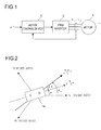
- Fig. 1 is a block configuration diagram of a motor drive system according to the first embodiment of the invention.
- the reference numeral 1 represents a three-phase permanent-magnet synchronous motor (hereinafter simply the "motor 1") having a permanent magnet on a rotor (unillustrated) and having an armature winding on a stator (unillustrated).
- motor 1 three-phase permanent-magnet synchronous motor
- the reference numeral 2 represents a PWM (pulse width modulation) inverter that, according to the rotor position of the motor 1, supplies three-phase alternating-current voltages, consisting of U-phase, V-phase, and W-phase voltages, to the motor 1. These voltages supplied to the motor 1 are collectively referred to as the motor voltage (armature voltage) V a , and the currents supplied from the PWM inverter 2 to the motor 1 are collectively referred to as the motor current (armature current) I a .
- the reference numeral 3 represents a motor control device that, based on the motor current I a , estimates the rotor position or the like of the motor 1, and feeds the PWM inverter 2 with a signal for rotating the motor 1 at a desired rotation speed.
- This desired rotation speed is fed, in the form of a specified motor speed value ⁇ * , from an unillustrated CPU (central processing unit) or the like to the motor control device 3.
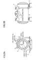
- Fig. 2 is an analysis model diagram of the motor 1.
- armature winding should be understood to mean the armature winding provided on the motor 1.
- Fig. 2 shows the U-phase, V-phase, and W-phase armature winding fixed axes.
- the reference numeral 1a represents the permanent magnet constituting the rotor of the motor 1.
- the d-axis In a rotating coordinate system that rotates at the same speed as the magnetic flux produced by the permanent magnet 1a, the direction of the magnetic flux produced by the permanent magnet 1a is referred to as the d-axis, and the axis estimated, for control purposes, as corresponding to the d-axis is referred to as the ⁇ -axis.
- the axis having a phase leading the d-axis by an electrical angle of 90 degrees is referred to as the q-axis
- the axis estimated to have a phase leading the ⁇ -axis by an electrical angle of 90 degrees is referred to as the ⁇ -axis.
- the coordinate axes of the rotating coordinate system having the d- and q-axes as its coordinate axes are called the d-q axes (real axes).
- the rotating coordinate system (estimated rotating coordinate system) estimated for control purposes has the ⁇ - and ⁇ -axes as its coordinate axes, and its coordinate axes are called the ⁇ - ⁇ axes.
- the d-q axes rotates, and its rotation speed (electrical angular velocity) is called the real motor speed ⁇ .
- the ⁇ - ⁇ axes also rotates, and its rotation speed (electrical angular velocity) is called the estimated motor speed ⁇ e .
- the phase of the d-axis at a given moment is represented, relative to the U-phase armature winding fixed axis, by ⁇ (real rotor position ⁇ ).
- the ⁇ -axis, ⁇ -axis, d-axis, and q-axis components of the motor voltage V a are referred to as the ⁇ -axis voltage v ⁇ , ⁇ -axis voltage v ⁇ , d-axis voltage v d , and q-axis voltage vq respectively;
- the ⁇ -axis, ⁇ -axis, d-axis, and q-axis components of the motor current I a are referred to as the ⁇ -axis current i ⁇ , ⁇ -axis current i ⁇ , d-axis current i d , and q-axis current i q respectively.
- R a represents the motor resistance (the resistance of the armature winding of the motor 1);
- L d and L q respectively represent the d-axis and q-axis inductances (the d-axis and q-axis components of the inductance of the armature winding of the motor 1);
- ⁇ a represents the armature flux linkage ascribable to the permanent magnet 1a.
- the values of L d , L q , R a , and ⁇ a are determined at the time of the fabrication of the motor drive system, and are used by the motor control device to perform calculations.
- s represents the Laplace operator.
- Fig. 3A is a front view of a horizontal compressor 4 incorporating the motor drive system shown in Fig. 1
- Fig. 3B is a side view of the horizontal compressor 4.
- the reference numeral 6 represents an installation surface on which the horizontal compressor 4 is placed.
- the horizontal compressor 4 is provided with fastenings 5 for fastening the horizontal compressor 4 to the installation surface 6. These fastenings 5 and the installation surface 6 are joined with fastening devices (unillustrated) such as bolts, whereby the horizontal compressor 4 is fastened to the installation surface 6.
- the motor 1 shown in Fig. 1 is secured inside the horizontal compressor 4 shown in Figs. 3A and 3B (how the motor 1 is secured is not shown here) in such a way that the rotation axis of the rotor of the motor 1 lies parallel to the installation surface 6.
- the compressor inside which the rotation axis of the rotor of the motor 1 lies parallel to the installation surface 6 is referred to as a horizontal compressor.
- parallel does not only mean “parallel” in the strict sense of the word; it covers a broader concept including “practically parallel”, which is somewhat deviated from the strict sense of the word.
- the rotation axis of the rotor of the motor 1 is horizontal, and is assumed to point in the direction along the longer sides of the horizontal compressor 4.
- the direction parallel to the rotation axis is referred to as the "horizontal direction”.
- the X-, Y-, and Z-axes define three-dimensional rectangular coordinates.
- the directions parallel to the X- and Y-axes are referred to as the X-direction and Y-direction respectively.
- the Y-direction is vertical to the installation surface 6; the X-direction is parallel to the installation surface 6.
- the horizontal direction is orthogonal to the X- and Y-directions.
- the origin of the two-dimensional plane be located on the rotation axis of the motor 1.
- the direction of the straight line passing through the origin is referred to as the radial direction, which is the same as the direction of the radius of the locus of the rotating rotor of the motor 1.
- the radial direction is the direction that is not parallel to both the X- and Y-directions.
- the circumferential direction is the direction orthogonal to the radial direction. This circumferential direction is the same as the tangential direction of the locus of the rotating rotor of the motor 1.
- the magnetic attractive force exerted in the radial direction between the permanent magnet 1a on the rotor and the stator causes the radial vibration of the stator, which is transmitted to a frame (unillustrated) that holds the stator. This causes the horizontal compressor 4 to vibrate, resulting in the generation of noise.
- a negative d-axis current is passed when a reluctance torque is used, or flux-weakening control is performed.
- flux-weakening control is performed at a rotation speed at which, if no negative d-axis current is passed, the terminal voltage of the motor exceeds a predetermined upper voltage limit. Passing the d-axis current more than necessary is undesirable because it will result in the reduction in efficiency. It is for this reason that usually the d-axis current that is equal to or greater than the d-axis current that achieves maximum torque control is not passed, or, at a rotation speed at which the terminal voltage is lower than the upper voltage limit, flux-weakening control is not performed.
- the negative d-axis current is passed deliberately so as to weaken the magnetic flux (armature flux linkage) produced by the permanent magnet 1a.
- the negative d-axis current how it is fed is changed appropriately according to the rotation speed of the rotor.
- the terminal voltage of the motor 1 is the voltage applied to the armature winding of the motor 1 by the PWM inverter 2.
- the above-mentioned upper voltage limit is set based on the power supply voltage supplied to the inverter 2, and the speed range described above is the speed range of the rotation speed of the rotor of the motor 1.
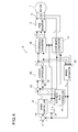
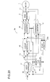
- Fig. 4 is a configuration block diagram of the motor drive system, and shows the specific internal configuration of the motor control device 3 shown in Fig. 1 .
- the motor control device 3 includes a current detector 11, a coordinate converter 12, a subtracter 13, a subtracter 14, a current controller 15, a magnetic flux controller 16, a speed controller 17, a coordinate converter 18, a subtracter 19, a speed estimator 20, and an integrator 21.
- the different parts constituting the motor control device 3 can freely use all the values produced within the motor control device 3 as necessary.
- the current detector 11 is realized with, for example, Hall devices or the like, and detects the U-phase current i u and the V-phase current i v , which are fixed-axis components of the motor current I a supplied from the PWM inverter 2 to the motor 1.
- the coordinate converter 12 receives the U-phase current i u and V-phase current i v detected by the current detector 11, and converts them into two-phase currents, namely the ⁇ -axis current i ⁇ and ⁇ -axis current i ⁇ , based on the estimated rotor position ⁇ e fed from the integrator 21 that functions as a position estimator.
- the speed estimator 20 estimates and outputs the estimated motor speed ⁇ e .
- the method by which the estimated motor speed ⁇ e is estimated will be described later.
- the integrator 21 integrates the estimated motor speed ⁇ e outputted from the speed estimator 20, and thereby calculates the estimated rotor position ⁇ e .
- the subtracter 19 subtracts from the specified motor speed value ⁇ * the estimated motor speed ⁇ e fed from the speed estimator 20, and outputs the result of the subtraction (speed error).
- This specified ⁇ -axis current value (specified torque current value) i ⁇ * represents the current value to be followed by the ⁇ -axis current i ⁇ , which is the ⁇ -axis component of the motor current I a .
- the magnetic flux controller 16 produces the specified ⁇ -axis current value i ⁇ * based on the estimated rotor position ⁇ e fed from the integrator 21 and the estimated motor speed ⁇ e fed from the speed estimator 20, and outputs it.
- This specified ⁇ -axis current value (specified excitation current value) i ⁇ * represents the current value to be followed by the ⁇ -axis current i ⁇ , which is the ⁇ -axis component of the motor current I a .
- the subtracter 13 subtracts the ⁇ -axis current i ⁇ from the specified ⁇ -axis current value i ⁇ * , and thereby calculates the current error (i ⁇ * - i ⁇ ).
- the subtracter 14 subtracts the ⁇ -axis current i ⁇ from the specified ⁇ -axis current value i ⁇ * , and thereby calculates the current error (i ⁇ * - i ⁇ ).
- the current controller 15 receives the current errors calculated by the subtracters 13 and 14, and thereby produces, by proportional-plus-integral control, the specified ⁇ -axis voltage value v ⁇ * and the specified ⁇ -axis voltage value v ⁇ * such that the ⁇ -axis current i ⁇ follows the specified ⁇ -axis current value i ⁇ * and in addition that the ⁇ -axis current i ⁇ follows the specified ⁇ -axis current value i ⁇ * , and outputs them; meanwhile, as necessary, i ⁇ , i ⁇ , and ⁇ e are referred to.
- the specified ⁇ -axis voltage value v ⁇ * represents the voltage value to be followed by the ⁇ -axis voltage v ⁇
- the specified ⁇ -axis voltage value v ⁇ * represents the voltage value to be followed by the ⁇ -axis voltage v ⁇ .
- the coordinate converter 18 Based on the estimated rotor position ⁇ e fed from the integrator 21, the coordinate converter 18 converts the two-phase specified voltage values, namely the specified ⁇ -axis voltage value v ⁇ * and specified ⁇ -axis voltage value v ⁇ * into specified three-phase voltage values consisting of a specified U-phase voltage value v u * , a specified V-phase voltage value v v * , and a specified W-phase voltage value v w * , and then outputs them to the PWM inverter 2.
- the PWM inverter 2 Based on the specified three-phase voltage values (v u * , v v * , and v w * ), which represent the voltages to be applied to the motor 1, the PWM inverter 2 produces pulse-width-modulated signals, and supplies the motor current I a commensurate with the specified three-phase voltage values to the motor 1 to drive it.
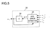
- Fig. 5 shows the internal blocks of the speed estimator 20.
- the estimated motor speed ⁇ e is estimated by the speed estimator 20.
- There have conventionally been proposed various methods for estimating the estimated motor speed ⁇ e and any method other than specifically described below can be adopted in the speed estimator 20.
- the speed estimator 20 shown in Fig. 5 includes an axis error estimator 25 and a proportional-plus-integral calculator 26.
- the axis error estimator 25 calculates the axis error ⁇ between the d-axis and the ⁇ -axis by using, for example, formula (1) below.
- p represents the differential operator.
- the values of v ⁇ * , v ⁇ * , and ⁇ e are used as the values of v ⁇ , v ⁇ , and ⁇ in formula (1).
- the axis error estimator 25 is fed with the values of v ⁇ * , v ⁇ * , i ⁇ , and i ⁇ from the current controller 15 and the coordinate converter 12, and is fed with the value of ⁇ e from the proportional-plus-integral calculator 26.
- the proportional-plus-integral calculator 26 cooperating with the different parts constituting the motor control device 3, performs proportional-plus-integral control to calculate the estimated motor speed ⁇ e such that the axis error ⁇ calculated by the axis error estimator 25 converges to zero.
- the estimated motor speed ⁇ e thus calculated is fed, as the value outputted from the speed estimator 20, to the different parts of the motor control device 3 that need it.
- the magnetic flux controller 16 which is one of the distinctive features of the motor drive system of this embodiment, will be described.
- the following description assumes that the number of pole pairs of the motor 1 is two. Needless to say, the number of pole pairs does not necessarily have to be two, but any number of pole pairs may be used.
- n in formula (2) is a coefficient associated with the electrical angular velocity
- the harmonics of order 1, 2, 3, ... appear in the electrical period (Te).
- Np 2
- the harmonics of order 2, 4, 6, ... appear in the mechanical period (Tm).
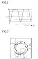
- Fig. 6 shows how the specified ⁇ -axis current value i ⁇ * varies according to the estimated rotor position ⁇ e .
- the specified ⁇ -axis current value i ⁇ * produces a waveform in the form of the negative half of the cosine waveform, and varies periodically in the current range in which the magnetic flux produced by the permanent magnet 1a is weakened.
- i ⁇ * and i ref * are varied at a speed k 1 times of the mechanical rotation speed (expressed in revolution per second (rps)) of the rotor, that is, at a frequency (k 1 / Np) times of ⁇ e , which is the fundamental frequency of i ⁇ * and i ref * .
- Fig. 7 shows the loci of the magnetic attractive forces in the fixed coordinate system.
- a curve 101 represents the magnetic attractive force in the radial direction when vector control is performed such that the d-axis current i d is kept equal to zero
- a curve 102 represents the magnetic attractive force in the radial direction when flux-weakening control is performed such that i d is kept at a given value (gain A).
- a curve 103 which corresponds to this embodiment, represents the locus of the magnetic attractive force in the radial direction when the d-axis current of fourth order (harmonic d-axis current) is injected.
- four periods worth of variations in i ⁇ * and i ref * appear every time the rotor is mechanically rotating one-turn. Accordingly, while the rotor is mechanically rotating one-turn, the magnetic attractive force in the radial direction becomes alternately stronger and weaker four times due to the variations in i ⁇ * .
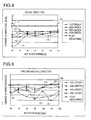
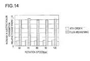
- Figs. 8 to 11 are diagrams each showing the dependence of the vibration level indicating the magnitude of the vibration of the horizontal compressor 4 on the rotation speed.
- Figs. 8 to 11 each show the results of the experiments in which the gain A and the phase ⁇ are kept at a constant gain A 0 and a certain phase ⁇ 0 respectively.
- the magnetic flux controller 16 shown in Fig. 4 determines i ⁇ * to be actually outputted.
- curves 111, 112, 113, and 114 respectively represent the dependence of the vibration level change on the rotation speed when d-axis currents of first, second, third, and fourth order are injected.
- a curve 115 represents the dependence of the vibration level change on the rotation speed when flux-weakening control is simply performed, that is, when i d having the magnitude A 0 is constantly passed.
- curves 121, 122, 123, and 124 respectively represent the dependence of the vibration level change on the rotation speed when the d-axis currents of first, second, third, and fourth order are injected.
- a curve 125 represents the dependence of the vibration level change on the rotation speed when flux-weakening control is simply performed, that is, when i d having the magnitude A 0 is constantly passed.
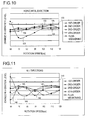
- curves 131, 132, 133, and 134 respectively represent the dependence of the vibration level change on the rotation speed when the d-axis currents of first, second, third, and fourth order are injected.
- a curve 135 represents the dependence of the vibration level change on the rotation speed when flux-weakening control is simply performed, that is, when i d having the magnitude A 0 is constantly passed.
- curves 141, 142, 143, and 144 respectively represent the dependence of the vibration level change on the rotation speed when the d-axis currents of first, second, third, and fourth order are injected.
- a curve 145 represents the dependence of the vibration level change on the rotation speed when flux-weakening control is simply performed, that is, when i d having the magnitude A 0 is constantly passed.
- the change in the level of vibration of the horizontal compressor 4 in all directions corresponds to the sum of the changes of the level of vibration in the radial, circumferential, and horizontal directions.
- the horizontal axis represents the rotation speed (rps) of the rotor of the motor 1.
- straight lines 110, 120, 130, and 140 shown in Figs. 8 to 11 represent no change in the vibration level, indicating that the vibration level becomes lower toward the lower end of the vertical axis (in the planes of these drawings).
- injecting the d-axis current of fourth order is most effective in reducing the level of vibration in the radial direction (assuming that the curve 115 is ignored).
- the d-axis currents of first and fourth order are approximately equally effective in reducing the level of vibration in the radial direction.
- injecting the d-axis current of fourth order is most effective in reducing the level of vibration in the circumferential direction; at rotation speeds of 70, 80, and 100 rps, injecting the d-axis current of first order is most effective; and, at rotation speeds of 90, 110, and 120 rps, injecting the d-axis current of second order is most effective.
- injecting the d-axis current of second (or fourth) order is most effective in reducing the level of vibration in the horizontal direction; at rotation speeds of 70, 80, and 90 rps, injecting the d-axis current of first order is most effective; and, at a rotation speed of 100 rps, injecting the d-axis current of first (or second) order is most effective.
- injecting the d-axis current of fourth order is most effective in reducing the level of vibration in all directions; at rotation speeds of 70, 80, and 100 rps, injecting the d-axis current of first order is most effective; and, at rotation speeds of 90, 110, and 120 rps, injecting the d-axis current of second order is most effective.
- the level of vibration in each direction varies with a change in the order of the d-axis current to be injected; it varies, even when the d-axis current of the same order is injected, at different rotation speeds. The reason is that a change in the order changes how the vibration is cancelled out, and that how the vibration is cancelled out depends on the rotation speed.
- the order of the d-axis current that should be injected at a certain rotation speed to reduce the vibration in the most effective way depends on, for example, the mechanical structural properties of the horizontal compressor 4.
- the optimum order depends on the direction of vibration to be reduced. For example, suppose that the rotation speed is 70 rps. Then, injecting the d-axis current of fourth order is best suited to reducing the vibration in the radial direction, while injecting the d-axis current of first order is best suited to reducing the vibration in the circumferential direction.
- the magnetic flux controller 16 shown in Fig. 4 dynamically sets the value of n in formula (2) according to the speed information commensurate with the rotation speed of the rotor, and produces i ⁇ * by using the value of n thus set.
- This embodiment deals with an example in which the estimated motor speed ⁇ e is used as the speed information.
- n simply has to be set equal to 2; when the rotation speed indicated thereby is 100 rps, n simply has to be set equal to 1/2 or 2.
- priority is given to reducing the vibration in the circumferential direction.
- the rotation speed indicated by the speed information is 80 rps, n simply has to be set equal to 1/2; when the rotation speed is 110 rps, n simply has to be set equal to 1.
- priority is given to reducing the vibration in all directions.
- n when the rotation speed indicated by the speed information is 60 rps, n simply has to be set equal to 2; when the rotation speed is 70 rps, n simply has to be set equal to 1/2. In this way, the d-axis current having the optimum frequency to reducing the vibration to be reduced is supplied, making it possible to effectively reduce the vibration.
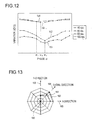
- Fig. 12 is a diagram showing the relationship between the level of vibration of the horizontal compressor 4 in the radial direction and the phase ⁇ .
- the vertical axis represents the level of vibration of the horizontal compressor 4 in the radial direction
- the horizontal axis represents the phase ⁇ .
- the vibration level becomes lower toward the lower end of the vertical axis (in the plane of this drawing).
- a broken line 151 represents the relationship between the level of vibration in the radial direction and the phase ⁇ when the rotation speed of the rotor is 40 rps
- broken lines 152, 153, and 154 represent the relationship between the level of vibration in the radial direction and the phase ⁇ when the rotation speeds of the rotor are 60, 80, and 100 rps respectively.
- the level of vibration in the radial direction varies with a change in the phase ⁇ ; it varies, even in the same phase ⁇ , at different rotation speeds.
- the reason is that a change in the phase ⁇ changes how the vibration in the radial direction is cancelled out, and that how the vibration is cancelled out depends on the rotation speed.
- the vibration in the radial direction reaches the lowest level; when the phase ⁇ is other than ⁇ 1 (for instance, when the phase ⁇ is ⁇ 2 or ⁇ 3 ), the vibration in the radial direction is not at the lowest level.
- the rotation speed is 80 rps.
- the vibration in the radial direction reaches the lowest level; when the phase ⁇ is other than ⁇ 2 (for instance, when the phase ⁇ is ⁇ 1 or ⁇ 3 ), the vibration in the radial direction is not at the lowest level.
- the vibration in the radial direction reaches the lowest level; when the phase ⁇ is other than ⁇ 3 (for instance, when the phase ⁇ is ⁇ 1 or ⁇ 2 ), the vibration in the radial direction is not at the lowest level.
- ⁇ 1 ⁇ ⁇ 2 ⁇ ⁇ 3 holds.
- phase ⁇ of the d-axis current that should be injected at a certain rotation speed to reduce the vibration in the most effective way depends on, for example, the mechanical structural properties of the horizontal compressor 4. In addition, the optimum phase ⁇ depends on the rotation speed.
- the magnetic flux controller 16 shown in Fig. 4 dynamically sets the phase ⁇ in formula (2) according to the speed information commensurate with the rotation speed of the rotor, and produces i ⁇ * by using the phase ⁇ thus set.
- This embodiment deals with an example in which the estimated motor speed ⁇ e is used as the speed information.
- n 2
- the rotation speed indicated by the speed information is 40 or 60 rps
- ⁇ simply has to be ⁇ 1
- the rotation speed indicated thereby is 100 rps
- ⁇ simply has to be ⁇ 3 .
- the d-axis current having the optimum phase to reducing the vibration to be reduced is supplied, making it possible to effectively reduce the vibration.
- the level of vibration in a first direction becomes relatively high, whereas the level of vibration in a second direction becomes relatively low.
- the first and second directions are mutually different directions, each being one of the radial direction, the circumferential direction, and the horizontal direction.
- ⁇ 4 ⁇ ⁇ 5 holds. This makes it possible to preferentially reduce the vibration in a particular direction by changing the phase ⁇ . For example, in a case where the problem arises from the vibration in the radial direction but not from the vibration in the circumferential or horizontal direction, it is possible to select the optimum phase ⁇ to reducing the vibration in the radial direction.
- the horizontal compressor 4 has its own specific resonance frequency depending on the mechanical structure thereof.
- the level of vibration is much higher than that observed at other frequencies.
- the frequency of the vibration of the horizontal compressor 4 depends on the rotation speed of the rotor of the motor 1.
- the magnetic flux controller 16 shown in Fig. 4 sets the gain A of i ⁇ * , which is outputted by the magnetic flux controller 16, to A 1 ;
- the magnetic flux controller 16 sets the gain A of i ⁇ * , which is outputted by the magnetic flux controller 16, to A 2 .
- ⁇ 1 ⁇ ⁇ 2 , and A 1 > A 2 . This makes it possible to prevent the vibration from becoming abnormally strong at a particular rotation speed.
- the d-axis current is varied according to the rotor position so as to reduce the cogging torque.
- the magnitude of the variations of the d-axis current has to be kept constant so as to cancel out a magnetic flux change that is determined solely by the positional relationship between the rotor and the stator. That is, according to the method disclosed in JP-A-2004-056839 , the magnitude of the variations of the d-axis current does not depend on the rotation speed.
- Fig. 13 is a diagram showing a comparison of the vibration levels observed when the method of this embodiment is adopted to those observed when i d is kept equal to 0.
- a broken line 161 connecting three measurement data points represents the results obtained by the method of this embodiment, whereas a broken line 162 connecting the other three measurement data points represents the results obtained when i d is kept equal to 0.
- the "method of this embodiment” means the method by which the magnetic flux controller 16 shown in Fig. 4 is made to output i ⁇ * given by formulae (2), (3a), and (3b), including the method by which the value of n, the phase ⁇ , and (or) the gain A are changed according to the speed information.
- the reference numeral 160 represents the origin.
- the level of vibration in the Y-direction (see Fig. 3A ) is increased.
- the level of vibration in the radial direction is increased.
- the level of vibration in the X-direction is increased.
- the levels of vibrations in the Y-, radial, and X-directions are all reduced by using the method of this embodiment.
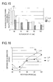
- Fig. 15 shows the results of comparison of the electric power consumption between the method of this embodiment and the method in which a positive/negative d-axis current is injected
- Fig. 16 shows the results of comparison of the vibration between them.
- the reference numeral 171 represents an increase in the electric power consumption observed when the method of this embodiment is adopted relative to a case where i d equals zero
- the reference numeral 172 represents an increase in the electric power consumption observed when the method in which a positive/negative d-axis current is injected is adopted relative to a case where i d equals zero. It is needless to say that, since only a negative d-axis current is injected in the method of this embodiment, the former suffers less from an increase in the electric power consumption than the latter at all rotation speeds (60 to 100 rps).
- a curve 181 represents a difference in vibration level between a case where i d equals zero and a case where the method of this embodiment is adopted
- a curve 182 represents a difference in vibration level between a case where i d equals zero and a case where the method in which a positive/negative d-axis current is injected is adopted.
- the vibration level becomes lower toward the lower end of the vertical axis (in the plane of the drawing).
- Fig. 16 shows a difference in levels of vibrations in the radial direction.
- both methods are equally effective in reducing the vibration level at all rotation speeds (60 to 100 rps).
- the reason is that, since the vibration in the radial direction is caused when the stator pulls the rotor, the vibration in the radial direction can be reduced only by weakening the force with which the stator pulls the rotor, that is, only by passing a negative d-axis current.
- the method of this embodiment is expected to reduce the vibration more effectively than the method in which a positive/negative d-axis current is injected since the former requires only a negative d-axis current to be injected, and is accordingly, unlike the latter, free from a period in which the magnetic attractive force is increased (an increase in the magnetic attractive force usually results in an increase in the vibration).
- the method of this embodiment does not vary, for example, the q-axis current for reducing the vibration, it is possible to reduce the magnetic attractive force without increasing torque pulsation.
- the first embodiment described above deals with a case in which the axis error ⁇ converges to zero. That is, the motor control device 3 according to the first embodiment estimates the d-q axes. As a result, i d and i ⁇ * are substantially equal. However, what has been explained in the first embodiment is also applicable to a case in which any axes other than the d-q axes is estimated. Hereinafter, a second embodiment will be described, taking up a case in which the dm-qm axes is estimated. What has been explained in the first embodiment can be applied, unless inconsistent, to the second embodiment.
- the dm-qm axes which is proposed by the applicant, is the axes estimated for control purposes. The technology relating to the dm-qm axes is discussed in detail in Japanese Patent Application No. 2006-177646 .
- dmqm method The method used in the second embodiment for estimating the dm-qm axes is hereinafter referred to as the "dmqm method".
- dmqm method The method used in the second embodiment for estimating the dm-qm axes.
- a common motor control device controls a motor so that the axis error ⁇ converges to zero.
- a formula for calculating the d-axis current i d for the purpose of maximum torque control exploiting a reluctance torque is widely known, and generally, to achieve maximum torque control, the specified ⁇ -axis current value i ⁇ * is calculated according to formula (4) below.
- i ⁇ * ⁇ a 2 ⁇ L q - L d - ⁇ a 2 4 ( L q - L d ⁇ ) 2 + i ⁇ * 2
- the dmqm method contributes to simplifying the adjustment of calculation parameters and reducing the amount of calculation. Now, the dmqm method will be described.
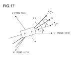
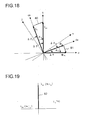
- Figs. 17 and 18 are analysis model diagrams of the motor 1 for explaining the dmqm method.
- Fig. 17 is a more detailed version of the analysis model diagram of Fig. 2 .
- the rotation axis whose direction coincides with that of the current vector to be fed to the motor 1 when maximum torque control is achieved is called the qm-axis.
- the rotation axis that lags behind the qm-axis by an electrical angle of 90 degrees is called the dm-axis.
- the coordinate axes consisting of the dm and qm-axes is called the dm-qm axes.
- the motor current that achieves maximum torque control has a positive q-axis component and a negative d-axis component.
- the qm-axis leads the q-axis in phase.
- the lead in phase occurs counter-clockwise in Figs. 17 and 18 .
- phase (angle) of the q-axis relative to the qm-axis is represented by ⁇ m
- the phase (angle) of the qm-axis relative to the ⁇ -axis is represented by ⁇ m
- the phase of the d-axis relative to the dm-axis also equals ⁇ m
- the phase of the dm-axis relative to the ⁇ -axis also equals ⁇ m
- ⁇ m represents is the lead angle of the qm-axis (dm-axis) relative to the q-axis (d-axis).
- ⁇ m is the axis error between the qm-axis and the ⁇ -axis (the axis error between the dm-qm axes and the ⁇ - ⁇ axes).
- ⁇ is the axis error between the d- and ⁇ -axes.
- the dm-axis and qm-axis components of the motor current I a are referred to as the dm-axis current i dm and the qm-axis current i qm respectively.
- the dm-axis and qm-axis components of the motor voltage V a are referred to as the dm-axis voltage v dm and the qm-axis voltage v qm respectively.
- the axis error ⁇ m between the qm-axis (dm-axis) and the ⁇ -axis ( ⁇ -axis) is estimated, and thereby the ⁇ -axis, which is an estimated axis, is made to converge to the dm-axis (i.e., the axis error ⁇ m is made to converge to zero).
- the motor current I a is broken down into the qm-axis current i qm parallel to the qm-axis and the dm-axis current i dm parallel to the dm-axis, and thereby the motor 1 is vector-controlled.
- Equation (33) Rearranging formula (30) based on formula (32) gives formula (33).
- E m is given by formula (34).
- L q1 represents the virtual inductance that depends on ⁇ m .
- L q1 is defined for the sake of convenience to handle the E ex ⁇ sin ⁇ m present in the second term in the right side of formula (30) as the voltage drop across the virtual inductance. Incidentally, L q1 is negative.
- formula (36) can be rearranged into formula (38) below. That is, just as formula (26) is rearranged into formula (28), performing coordinate conversion so that formula (36) on the dm-qm axes is converted into one on the ⁇ - ⁇ axes gives formula (38).
- v ⁇ v ⁇ R a + pL d - ⁇ ⁇ L m ⁇ ⁇ L m R a + pL d [ i ⁇ i ⁇ ] + E exm [ - sin ⁇ m cos ⁇ m ] - p ⁇ ⁇ m ⁇ L d [ - i ⁇ i ⁇ ]
- E exm ⁇ ⁇ L d - L q ⁇ i d + ⁇ a - L d - L q ⁇ pi q ⁇ cos ⁇ m + ⁇ ⁇ L q - L m ⁇ i dm ⁇ ⁇ ⁇ L d - L q ⁇ i ⁇ ⁇ sin ⁇ m + ⁇ a - L d - L q ⁇ pi q ⁇ cos ⁇ m + ⁇ ⁇ L q - L m ⁇ i dm ⁇ ⁇ ⁇ L d - L q ⁇ i ⁇ sin ⁇ m + ⁇ a ⁇ cos ⁇ m
- E ex can be called an extension induction voltage vector.
- the extension induction voltage vector E ex is an induction voltage vector on the q-axis.
- the extension induction voltage vector E ex can be broken into an induction voltage vector on the qm-axis and an induction voltage vector on the dm-axis.
- the induction voltage vector on the qm-axis is E m ; and the induction voltage vector (E ex ⁇ sin ⁇ m ) on the dm-axis, indicated by the reference numeral 80 in Fig. 18 , is the voltage drop vector attributable to the virtual inductance L q1 .
- E exm is the sum of E m and ⁇ (L q - L m )i dm .
- E exm is an induction voltage vector on the qm-axis.
- i dm ⁇ 0, and hence E exm is (substantially) equal to E m .
- E ex is an induction voltage generated by the flux linkage ⁇ ex of the motor 1 and the rotation of the motor 1.
- ⁇ ex is calculated by dividing E ex by ⁇ (assuming that the transient term (the second term in the right side) of E ex given by formula (27) is ignored).
- the flux linkage vector ⁇ ex is a flux linkage vector on the d-axis.
- ⁇ exm E exm / ⁇ ; then ⁇ exm is the sum of ⁇ m and (L q -L m )i dm .
- ⁇ exm is a flux linkage vector on the dm-axis.
- i dm ⁇ 0, and hence ⁇ exm is (substantially) equal to ⁇ m .
- Fig. 20 is a configuration block diagram of a motor drive system according to the second embodiment.
- the motor drive system according to the second embodiment includes a motor 1, a PWM inverter 2, and a motor control device 3a.
- the motor control device 3a (and the motor drive system) according to the second embodiment includes, instead of the speed estimator 20 provided in the motor control device 3 (and the motor drive system) shown in Fig. 4 , a speed estimator 20a.
- the motor control device 3a (and the motor drive system) according to the second embodiment is the same as the motor control device 3 (and the motor drive system) shown in Fig. 4 . Therefore, no overlapping description of the common features will be repeated.
- the motor 1 is a salient-pole motor (a motor having a salient pole) as exemplified by an interior permanent magnet synchronous motor.
- the different parts constituting the motor control device 3a can freely use all the values produced within the motor control device 3a as necessary.
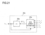
- Fig. 21 is an internal block diagram of the speed estimator 20a shown in Fig. 20 .
- the speed estimator 20a includes an axis error estimator 25a and a proportional-plus-integral calculator 26a.
- the axis error estimator 25a calculates the axis error ⁇ m based on all or part of v ⁇ * , v ⁇ * , i ⁇ , and i ⁇ .
- the proportional-plus-integral calculator 26a performs proportional-plus-integral control to calculate the estimated motor speed ⁇ e such that the axis error ⁇ m calculated by the axis error estimator 25a converges to zero.
- Various methods for estimating the axis error ⁇ m can be adopted to make the axis error estimator 25a estimate the axis error ⁇ m .
- the axis error estimator 25a substitutes the values of v ⁇ * , v ⁇ * , and ⁇ e for the values of v ⁇ , v ⁇ , and ⁇ whenever they appear in the formula.
- the axis error estimator 25a calculates the axis error ⁇ m according to formula (41) below.
- the ⁇ -axis and ⁇ -axis components of the induction voltage vector E exm are represented by E exm ⁇ and E exm ⁇ respectively.
- ⁇ m tan -1 -E exm ⁇ / E exm ⁇ ) holds.
- ⁇ m is given by formula (41) below (assuming that the third term in the right side of formula (38) is ignored).
- i d ⁇ a 2 ⁇ L q - L d - ⁇ a 2 4 ( L q - L d ⁇ ) 2 + i q 2
- the value of L m may be calculated by assuming that i ⁇ ⁇ i qm and using an approximation formula that gives L m as a function of i ⁇ ; or different values of L m corresponding to different values of i ⁇ may be previously prepared in the form of table data so that the value of L m is determined by referring to the table data.
- the value of L m may be fixed; that is, L m may be given a value that remains fixed irrespective of the value of i ⁇ .
- the axis error estimator 25a can calculate the axis error ⁇ m according to formula (46), (47), or (48) below.
- the value of E exm in formula (46) can be calculated according to formula (39) above.
- To calculate the value of E exm an approximation can be made as appropriate.
- the symbols ⁇ exm ⁇ and ⁇ exm ⁇ respectively represent ⁇ -axis and ⁇ -axis components of the flux linkage vector ⁇ exm .
- the magnetic flux controller 16 like the magnetic flux controller 16 shown in Fig. 4 , produces and outputs the specified ⁇ -axis current value (specified excitation current value) i ⁇ * given by formulae (2), (3a), and (3b).
- the magnetic flux controller 16 provided in the motor control device 3a can change the value of n, the phase ⁇ , and (or) the gain A according to the speed information indicating the rotation speed of the rotor. This makes it possible to achieve the same effects as those achieved in the first embodiment.
- the motor speed ⁇ and the rotor position ⁇ are estimated. Instead, they may be detected by using a resolver (unillustrated) or the like.
- the magnetic flux controller 16 shown in Fig. 4 produces the specified ⁇ -axis current value i ⁇ * as the specified excitation current value by using the detected real rotor position ⁇ and real motor speed ⁇ as ⁇ e and ⁇ e , respectively.
- the ⁇ -axis is not an estimated axis but (ideally) the d-axis itself.
- n may be given a value such as 1.1 or 2.3.
- the first embodiment deals with a case in which the magnetic flux controller 16 outputs i ⁇ * itself given by formulae (2), (3a), and (3b).
- the magnetic flux controller 16 outputs i ⁇ * itself given by formulae (2), (3a), and (3b).
- the specified ⁇ -axis current value i ⁇ * given by formulae (2), (3a), and (3b) serves as a superposition specified ⁇ -axis current value for reducing the vibration.
- the magnetic flux controller 16 calculates the value of the right side of formula (4) above as the basic specified ⁇ -axis current value, and calculates i ⁇ * given by formulae (2), (3a), and (3b) as the superposition specified ⁇ -axis current value. Then, the magnetic flux controller 16 feeds the sum of the basic specified ⁇ -axis current value and the superposition specified ⁇ -axis current value to the subtracter 13 as a specified ⁇ -axis current value (specified excitation current value) to be finally outputted by the magnetic flux controller 16.
- the subtracter 13 outputs, to the current controller 15, the current error between the specified ⁇ -axis current value (i.e., the sum of the basic specified ⁇ -axis current value and the superposition specified ⁇ -axis current value) and the ⁇ -axis current i ⁇ .
- the specified ⁇ -axis current value i.e., the sum of the basic specified ⁇ -axis current value and the superposition specified ⁇ -axis current value
- the second embodiment aims to achieve maximum torque control (or control similar to it). However, it is also possible to achieve any other desired vector control than maximum torque control by exploiting the features specifically described above.
- the rotation axis which leads in phase the rotation axis whose direction coincides with that of the current vector to be fed to the motor 1 to achieve maximum torque control is adopted as the qm-axis. This helps reduce iron loss, and thereby improve the efficiency of the motor. Giving an appropriate phase lead to the qm-axis helps achieve maximum efficiency control.
- the value of L m is calculated according to formula (42) above; to improve the efficiency of the motor, a value smaller than the value actually calculated according to formula (42) above is adopted as the value of L m .
- the current detector 11 may be so configured as to directly detect the motor current.
- the current detector 11 may be so configured as to detect the motor current by reproducing the motor current from the instantaneous current of the direct current on the power supply side.
- part or all of the functions of the motor control device is realized, for example, with software (a program) incorporated in a general-purpose microcomputer or the like.
- software a program
- the block diagrams showing the configurations of different parts of the motor control device serve as functional block diagrams.
- the motor control device may be realized with hardware alone, instead of software (a program).
- the coordinate converters 12 and 18, the subtracters 13 and 14, and the current controller 15 constitute a specified voltage value calculator.
- the magnetic flux controller 16, the speed controller 17, and the subtracter 19 constitute a specified current value calculator.
- the specified ⁇ -axis current value outputted from the magnetic flux controller 16 corresponds to the specified excitation current value (the specified current value corresponding to the d-axis current).
- the present invention is suitable for electric devices of any kind that use a motor; for example, it is suitable for electric cars that run by exploiting the rotation of a motor, and compressors and the like used in air conditioners and the like.
Landscapes
- Engineering & Computer Science (AREA)
- Power Engineering (AREA)
- Control Of Ac Motors In General (AREA)
- Control Of Motors That Do Not Use Commutators (AREA)
Claims (8)
- Motorsteuervorrichtung (3, 3a),
wobei die Motorsteuervorrichtung (3, 3a) einen Motor (1) steuert, der mit einem Rotor gebaut ist, der einen Permanentmagneten (1a) aufweist, und mit einem Stator, der eine Ankerwicklung aufweist,
wobei, wenn eine Achse parallel zu einem Magnetfluss, der durch den Permanentmagneten erzeugt wird, d-Achse genannt wird und eine Achse senkrecht zur d-Achse, q-Achse genannt wird,
die Motorsteuervorrichtung (3, 3a) Folgendes umfasst:einen Rechner für spezifizierte Stromwerte (16; 17; 19), der spezifizierte Stromwerte (iγ; iδ*) als einen spezifizierten Erregerstromwert (iγ*) beziehungsweise als einen spezifizierten Drehmomentstromwert (iδ*) entsprechend den d-Achsen- und den q-Achsen-Komponenten eines Stromes, der durch die Ankerwicklung läuft, ableitet; undeinen Stromcontroller (15), der basierend auf dem spezifizierten Erregerstromwert (iγ*) und dem spezifizierten Drehmomentstromwert (iδ*) den Strom steuert, der durch die Ankerwicklung läuft,wobei der Rechner für spezifizierte Stromwerte basierend auf einer geschätzten oder erkannten Rotorposition (θe) und innerhalb eines Geschwindigkeitsbereiches einer Rotationsgeschwindigkeit des Rotors, in dem die d-Achsen-Komponente des Stromes nicht negativ ist und eine an den Motor angelegte Spannung gleich oder geringer als eine vorbestimmte obere Spannungsgrenze ist, die periodische Veränderung nur des spezifizierten Erregerstromwertes (iγ*) bewirkt, auf eine Weise, dass der spezifizierte Erregerstromwert (iγ*) in einem Bereich von Werten verändert wird, in dem der Magnetfluss mit einer Frequenz, die sich proportional zur Rotationsgeschwindigkeit verhält, schwächer wird. - Motorsteuervorrichtung nach Anspruch 1,
wobei, wenn die Rotationsgeschwindigkeit (ωe; ω*) bei einer gegebenen ersten Rotationsgeschwindigkeit oder einer gegebenen zweiten Rotationsgeschwindigkeit, die sich von der ersten Rotationsgeschwindigkeit unterscheidet, feststehend ist, der Rechner für spezifizierte Stromwerte den spezifizierten Erregerstromwert (iγ*) mit einer Frequenz verändert, die proportional zur Rotationsgeschwindigkeit (ωe; ω*) ist,
wobei der Rechner für spezifizierte Stromwerte derart konfiguriert ist, dass er einen Proportionalitätskoeffizienten (k1) zwischen der Frequenz und der Rotationsgeschwindigkeit (ωe; ω*) ändert, abhängig davon, ob die Rotationsgeschwindigkeit (ωe; ω*) die erste Rotationsgeschwindigkeit oder die zweite Rotationsgeschwindigkeit ist. - Motorsteuervorrichtung nach Anspruch 1 oder 2, wobei
der Rechner für spezifizierte Stromwerte derart konfiguriert ist, dass er eine Phase (α) der Veränderungen des spezifizierten Erregerstromwertes (iγ*) gemäß der Rotationsgeschwindigkeit (ωe; ω*) ändert. - Motorsteuervorrichtung nach einem der Ansprüche 1 bis 3, wobei
der Rechner für spezifizierte Stromwerte derart konfiguriert ist, dass er eine Amplitude (A) von Veränderungen des spezifizierten Erregerstromwertes (iγ*) gemäß der Rotationsgeschwindigkeit ändert. - Motorsteuervorrichtung nach Anspruch 2,
wobei für den Proportionalitätskoeffizienten mehrere mögliche Proportionalitätskoeffizienten eingestellt sind,
wobei der Proportionalitätskoeffizient (k1) basierend auf Vibrationszuständen einer Vorrichtung (4) bestimmt wird, welche die Motorsteuervorrichtung (3; 3a) enthält, wobei die Vibrationszustände beobachtet werden, wenn die mehreren möglichen Proportionalitätskoeffizienten einzeln als der Proportionalitätskoeffizient übernommen werden. - Motorsteuervorrichtung nach Anspruch 3,
wobei für die Phase (α) mehrere mögliche Phasen eingestellt sind,
wobei die Phase (α) basierend auf Vibrationszuständen einer Vorrichtung (4) bestimmt wird, welche die Motorsteuervorrichtung (3; 3a) enthält, wobei die Vibrationszustände beobachtet werden, wenn die mehreren möglichen Phasen einzeln als die Phase (α) übernommen werden. - Motorantriebssystem, Folgendes umfassend:einen Motor (1);einen Umrichter, der den Motor (1) antreibt; unddie Motorsteuervorrichtung (3; 3a) nach einem der Ansprüche 1 bis 6, wobei die Motorsteuervorrichtung (3;3a) den Motor (1) durch Steuern des Umrichters steuert.
- Motorantriebssystem nach Anspruch 7, wobei
das Motorantriebssystem in einem horizontalen Kompressor (4) verwendet wird.
Applications Claiming Priority (1)
| Application Number | Priority Date | Filing Date | Title |
|---|---|---|---|
| JP2006187330A JP4789720B2 (ja) | 2006-07-07 | 2006-07-07 | モータ制御装置 |
Publications (3)
| Publication Number | Publication Date |
|---|---|
| EP1876702A2 EP1876702A2 (de) | 2008-01-09 |
| EP1876702A3 EP1876702A3 (de) | 2010-06-16 |
| EP1876702B1 true EP1876702B1 (de) | 2014-02-12 |
Family
ID=38577463
Family Applications (1)
| Application Number | Title | Priority Date | Filing Date |
|---|---|---|---|
| EP07111726.1A Not-in-force EP1876702B1 (de) | 2006-07-07 | 2007-07-04 | Motorreglungsvorrichtung |
Country Status (4)
| Country | Link |
|---|---|
| US (1) | US7710066B2 (de) |
| EP (1) | EP1876702B1 (de) |
| JP (1) | JP4789720B2 (de) |
| CN (1) | CN101102089B (de) |
Families Citing this family (46)
| Publication number | Priority date | Publication date | Assignee | Title |
|---|---|---|---|---|
| JP4754417B2 (ja) * | 2006-06-26 | 2011-08-24 | 本田技研工業株式会社 | 永久磁石型回転電機の制御装置 |
| US8264176B2 (en) * | 2007-11-19 | 2012-09-11 | EBM-Papst St. Georgen GmbH & Co. KG. | Fan arrangement |
| JP4804496B2 (ja) * | 2008-03-18 | 2011-11-02 | 三菱電機株式会社 | 電動機の駆動装置、空気調和機、洗濯機、洗濯乾燥機、冷蔵庫、換気扇、ヒートポンプ給湯器 |
| JP2009232498A (ja) * | 2008-03-19 | 2009-10-08 | Sanyo Electric Co Ltd | モータ制御装置 |
| JP5259241B2 (ja) * | 2008-04-23 | 2013-08-07 | 株式会社東芝 | モータ制御装置,モータ駆動システム,洗濯機,空調機,永久磁石モータの着磁量変更方法 |
| JP5468215B2 (ja) * | 2008-06-09 | 2014-04-09 | ダイキン工業株式会社 | 空気調和機及び空気調和機の製造方法 |
| JP5165545B2 (ja) * | 2008-12-08 | 2013-03-21 | 本田技研工業株式会社 | 電動機の磁極位置推定装置 |
| JP5186352B2 (ja) * | 2008-12-12 | 2013-04-17 | 本田技研工業株式会社 | 電動機の磁極位置推定装置 |
| EP2276162B1 (de) * | 2009-07-17 | 2012-10-03 | ebm-papst Mulfingen GmbH & Co. KG | Verfahren und Steuersystem zum Ansteuern eines bürstenlosen Elektromotors |
| EP2421146B1 (de) * | 2010-08-16 | 2015-02-11 | Baumüller Nürnberg GmbH | Vorrichtung und Verfahren zur drehgeberlosen Identifikation magnetomechanischer Kenngrößen eines Drehstrom-Synchronmotors |
| JP4983970B2 (ja) * | 2010-09-16 | 2012-07-25 | セイコーエプソン株式会社 | モーター制御装置 |
| JP5333583B2 (ja) * | 2010-11-08 | 2013-11-06 | トヨタ自動車株式会社 | 回転角算出装置および回転角算出方法 |
| CN102223133B (zh) * | 2011-06-02 | 2013-05-08 | 西北工业大学 | 一种凸极式永磁同步电机的最大转矩控制方法 |
| CN102403937B (zh) * | 2011-11-20 | 2013-10-30 | 中国科学院光电技术研究所 | 永磁同步电机中齿槽力矩的测量及抑制系统与实现方法 |
| JP2013143879A (ja) * | 2012-01-12 | 2013-07-22 | Panasonic Corp | インバータ制御装置 |
| CN102790583B (zh) * | 2012-08-06 | 2015-08-05 | 江苏大学 | 无轴承永磁同步电机径向广义逆内模控制器的构造方法 |
| US8866423B2 (en) | 2012-08-21 | 2014-10-21 | General Electric Company | PMSM field weakening for appliance motors |
| CN103107764B (zh) * | 2013-01-31 | 2015-07-15 | 浙江吉利汽车研究院有限公司杭州分公司 | 一种车用永磁同步电机弱磁控制方法 |
| CN103166547B (zh) * | 2013-03-14 | 2015-04-15 | 西安交通大学 | 一种调节谐波转矩的开关磁通永磁电机激振源 |
| CN103296959B (zh) * | 2013-05-29 | 2015-10-28 | 西安交通大学 | 永磁同步电机无速度传感器控制系统及方法 |
| CN103532462B (zh) * | 2013-09-17 | 2016-04-13 | 四川长虹电器股份有限公司 | 永磁同步电机低频转矩补偿过渡控制方法 |
| CN103647490B (zh) * | 2013-09-27 | 2016-06-08 | 天津大学 | 一种永磁电机的滑模控制策略 |
| DE102013223624A1 (de) * | 2013-11-20 | 2015-05-21 | Robert Bosch Gmbh | Verfahren zum Ansteuern einer elektrischen Maschine |
| KR101628145B1 (ko) * | 2014-06-16 | 2016-06-09 | 현대자동차 주식회사 | 전동기의 센서리스 제어 방법 및 시스템 |
| KR101535036B1 (ko) * | 2014-08-25 | 2015-07-24 | 현대자동차주식회사 | 구동모터의 전류지령에 대한 토크 보상장치 및 방법 |
| CN105591582B (zh) * | 2014-10-23 | 2019-01-29 | 比亚迪股份有限公司 | 永磁同步电机的控制方法及控制装置 |
| CN104702168A (zh) * | 2015-03-26 | 2015-06-10 | 北京经纬恒润科技有限公司 | 一种弱磁控制方法及装置 |
| JP6052323B2 (ja) * | 2015-04-02 | 2016-12-27 | 株式会社明電舎 | 電動機制御装置の回転子位置検出器異常判定装置 |
| JP6580899B2 (ja) * | 2015-08-26 | 2019-09-25 | 株式会社東芝 | ドライブシステムおよびインバータ装置 |
| KR101684182B1 (ko) * | 2015-10-14 | 2016-12-07 | 현대자동차주식회사 | 모터 제어기의 외란 보상 시스템 |
| CN105337550B (zh) * | 2015-12-02 | 2018-02-16 | 深圳市百盛传动有限公司 | 一种永磁同步电机转矩脉动抑制方法 |
| CN107659230B (zh) * | 2016-07-26 | 2021-01-15 | 广州极飞科技有限公司 | 电机矢量控制方法、装置和飞行器 |
| CN106208865B (zh) * | 2016-08-10 | 2018-09-18 | 天津工业大学 | 基于负载观测器的多永磁同步电机虚拟总轴控制方法 |
| EP3337031B1 (de) * | 2016-12-13 | 2020-06-17 | ABB Schweiz AG | Verfahren und vorrichtung zur detektion der anwesenheit eines dauermagneten eines rotors einer synchronmaschine |
| JP6288330B1 (ja) * | 2017-02-20 | 2018-03-07 | 株式会社安川電機 | 電動機制御装置及び電動機制御方法 |
| DE112018001520T5 (de) * | 2017-03-23 | 2019-12-05 | Nidec Corporation | Motorsteuerverfahren, motorsteuersystem und elektrisches servolenksystem |
| CN108696213A (zh) * | 2017-04-05 | 2018-10-23 | 南京海益开电子科技有限公司 | 电动工具的电机输出参数控制方法和电动工具 |
| CN107404260B (zh) * | 2017-08-31 | 2020-04-03 | 广东美芝制冷设备有限公司 | 压缩机高频谐波转矩补偿方法、压缩机控制器及空调器 |
| CN107565862B (zh) * | 2017-09-08 | 2019-09-24 | 华中科技大学 | 一种适用于永磁同步电机的速度波动抑制方法 |
| JP6870562B2 (ja) * | 2017-10-10 | 2021-05-12 | 株式会社デンソー | 回転電機の制御装置 |
| US10312842B2 (en) | 2017-10-26 | 2019-06-04 | Hamilton Sundstrand Corporation | Variable torque electric motor assembly |
| CN108390612B (zh) * | 2018-03-13 | 2022-03-11 | 江西精骏电控技术有限公司 | 一种基于查表方式的永磁同步电机的弱磁控制方法 |
| EP3547512A1 (de) * | 2018-03-28 | 2019-10-02 | KONE Corporation | Elektrischer linearmotor |
| CN110601627B (zh) * | 2019-07-11 | 2021-09-21 | 天津理工大学 | 一种pmsm的可拓展电压空间矢量输出的fcs-mpdtc控制系统及方法 |
| CN110707968B (zh) * | 2019-09-10 | 2021-11-30 | 苏州安驰控制系统有限公司 | 一种单锭控制系统的控制方法、系统及计算机存储介质 |
| CN110661390B (zh) * | 2019-09-24 | 2021-05-25 | 江苏大学 | 一种12/14极磁悬浮开关磁阻电机悬浮力精确建模方法 |
Family Cites Families (14)
| Publication number | Priority date | Publication date | Assignee | Title |
|---|---|---|---|---|
| US4950966A (en) * | 1989-07-03 | 1990-08-21 | Westinghouse Electric Corp. | Adaptive vibration canceller |
| US5272429A (en) * | 1990-10-01 | 1993-12-21 | Wisconsin Alumni Research Foundation | Air gap flux measurement using stator third harmonic voltage and uses |
| US5886493A (en) * | 1995-02-16 | 1999-03-23 | The Kansai Electric Power Co., Inc. | Synchronous machine excitation control device for absorbing harmonics superposed onto fundamental current |
| JP3667903B2 (ja) * | 1996-11-20 | 2005-07-06 | 三菱電機株式会社 | 圧縮機用電動機の制御装置 |
| US5936378A (en) * | 1997-03-27 | 1999-08-10 | Matsushita Electric Industrial Co., Ltd. | Motor controller |
| JP3366858B2 (ja) | 1998-05-29 | 2003-01-14 | 株式会社日立製作所 | 回転電機の制御装置 |
| JP3690341B2 (ja) | 2001-12-04 | 2005-08-31 | ダイキン工業株式会社 | ブラシレスdcモータ駆動方法およびその装置 |
| JP3766348B2 (ja) * | 2002-05-20 | 2006-04-12 | 三菱電機株式会社 | 電動機のトルク制御装置及び電動機のトルク制御方法及び密閉形圧縮機及び冷凍サイクル装置 |
| JP4110865B2 (ja) | 2002-07-16 | 2008-07-02 | 日産自動車株式会社 | 永久磁石型電動機の制御システム |
| JP4155155B2 (ja) | 2002-10-17 | 2008-09-24 | 株式会社デンソー | 交流回転電機の磁気騒音低減方法及びそれを用いるモータ制御装置 |
| EP1553693B1 (de) * | 2002-10-17 | 2007-12-19 | Denso Corporation | Wechselstromelektrodrehmaschine mit verringerungsverfahren für magnetisches rauschen, motorsteuereinrichtung und wechselstromelektrodrehmaschine damit |
| JP2005253155A (ja) | 2004-03-02 | 2005-09-15 | Toyota Motor Corp | 電動機 |
| JP2005328691A (ja) * | 2004-04-15 | 2005-11-24 | Denso Corp | モータ制御装置 |
| JP4422567B2 (ja) * | 2004-06-30 | 2010-02-24 | 株式会社日立製作所 | モータ駆動装置,電動アクチュエータおよび電動パワーステアリング装置 |
-
2006
- 2006-07-07 JP JP2006187330A patent/JP4789720B2/ja not_active Expired - Fee Related
-
2007
- 2007-07-03 US US11/822,208 patent/US7710066B2/en active Active
- 2007-07-04 EP EP07111726.1A patent/EP1876702B1/de not_active Not-in-force
- 2007-07-05 CN CN200710127430XA patent/CN101102089B/zh not_active Expired - Fee Related
Also Published As
| Publication number | Publication date |
|---|---|
| JP4789720B2 (ja) | 2011-10-12 |
| EP1876702A3 (de) | 2010-06-16 |
| CN101102089A (zh) | 2008-01-09 |
| JP2008017642A (ja) | 2008-01-24 |
| CN101102089B (zh) | 2012-06-13 |
| US7710066B2 (en) | 2010-05-04 |
| US20080018296A1 (en) | 2008-01-24 |
| EP1876702A2 (de) | 2008-01-09 |
Similar Documents
| Publication | Publication Date | Title |
|---|---|---|
| EP1876702B1 (de) | Motorreglungsvorrichtung | |
| US7808203B2 (en) | Motor control device | |
| JP3411878B2 (ja) | 同期モータの回転子位置推定方法、位置センサレス制御方法及び制御装置 | |
| US7679308B2 (en) | Motor control device | |
| US6771039B2 (en) | Motor control apparatus and method | |
| EP1940016B1 (de) | Motorsteuervorrichtung und Motorsteuerverfahren | |
| JP4909797B2 (ja) | モータ制御装置 | |
| US7443130B2 (en) | Motor driving control device | |
| JP3802894B2 (ja) | Acマシンのためのセンサーレス位置制御アルゴリズム | |
| KR101046802B1 (ko) | 교류 회전기의 제어 장치 및 이 제어 장치를 사용한 교류회전기의 전기적 정수 측정 방법 | |
| US8044622B2 (en) | Sensorless control apparatus of synchronous motor | |
| JP2002095300A (ja) | 永久磁石同期電動機の制御方法 | |
| US10637381B2 (en) | Inverter control device and drive system | |
| EP1681762A2 (de) | Synchronmotorantriebssystem und Verfahren | |
| JP2009171680A (ja) | 永久磁石形同期電動機の制御装置 | |
| JP7001064B2 (ja) | モータ制御装置、モータシステム、モータ制御方法、および集積回路装置 | |
| JP2002272195A (ja) | 同期電動機の制御装置 | |
| JP5652701B2 (ja) | モータ駆動制御装置 | |
| JP7472397B2 (ja) | 電力変換装置、推定器及び推定方法 | |
| WO2022154027A1 (ja) | モータ制御装置およびそれを備えた駆動システム | |
| WO2024034501A1 (ja) | 永久磁石同期電動機の駆動装置、および制御方法 | |
| JP2017055637A (ja) | モータの巻き線に生じる逆起電圧に基づきモータを制御するモータ制御装置 | |
| JP2023146491A (ja) | オフセット量検出装置、およびオフセット量検出方法 |
Legal Events
| Date | Code | Title | Description |
|---|---|---|---|
| PUAI | Public reference made under article 153(3) epc to a published international application that has entered the european phase |
Free format text: ORIGINAL CODE: 0009012 |
|
| AK | Designated contracting states |
Kind code of ref document: A2 Designated state(s): AT BE BG CH CY CZ DE DK EE ES FI FR GB GR HU IE IS IT LI LT LU LV MC MT NL PL PT RO SE SI SK TR |
|
| AX | Request for extension of the european patent |
Extension state: AL BA HR MK YU |
|
| PUAL | Search report despatched |
Free format text: ORIGINAL CODE: 0009013 |
|
| AK | Designated contracting states |
Kind code of ref document: A3 Designated state(s): AT BE BG CH CY CZ DE DK EE ES FI FR GB GR HU IE IS IT LI LT LU LV MC MT NL PL PT RO SE SI SK TR |
|
| AX | Request for extension of the european patent |
Extension state: AL BA HR MK RS |
|
| 17P | Request for examination filed |
Effective date: 20101201 |
|
| AKX | Designation fees paid |
Designated state(s): AT BE BG CH CY CZ DE DK EE ES FI FR GB GR HU IE IS IT LI LT LU LV MC MT NL PL PT RO SE SI SK TR |
|
| 17Q | First examination report despatched |
Effective date: 20130218 |
|
| GRAP | Despatch of communication of intention to grant a patent |
Free format text: ORIGINAL CODE: EPIDOSNIGR1 |
|
| INTG | Intention to grant announced |
Effective date: 20130906 |
|
| GRAS | Grant fee paid |
Free format text: ORIGINAL CODE: EPIDOSNIGR3 |
|
| GRAA | (expected) grant |
Free format text: ORIGINAL CODE: 0009210 |
|
| RAP1 | Party data changed (applicant data changed or rights of an application transferred) |
Owner name: SANYO ELECTRIC CO., LTD. |
|
| AK | Designated contracting states |
Kind code of ref document: B1 Designated state(s): AT BE BG CH CY CZ DE DK EE ES FI FR GB GR HU IE IS IT LI LT LU LV MC MT NL PL PT RO SE SI SK TR |
|
| REG | Reference to a national code |
Ref country code: GB Ref legal event code: FG4D |
|
| REG | Reference to a national code |
Ref country code: CH Ref legal event code: EP |
|
| REG | Reference to a national code |
Ref country code: AT Ref legal event code: REF Ref document number: 652508 Country of ref document: AT Kind code of ref document: T Effective date: 20140215 |
|
| REG | Reference to a national code |
Ref country code: IE Ref legal event code: FG4D |
|
| REG | Reference to a national code |
Ref country code: DE Ref legal event code: R096 Ref document number: 602007035042 Country of ref document: DE Effective date: 20140327 |
|
| REG | Reference to a national code |
Ref country code: DE Ref legal event code: R083 Ref document number: 602007035042 Country of ref document: DE |
|
| RIN2 | Information on inventor provided after grant (corrected) |
Inventor name: TOMIGASHI, YOSHIO Inventor name: HASHIMOTO, EIICHIRO |
|
| REG | Reference to a national code |
Ref country code: NL Ref legal event code: VDEP Effective date: 20140212 |
|
| REG | Reference to a national code |
Ref country code: AT Ref legal event code: MK05 Ref document number: 652508 Country of ref document: AT Kind code of ref document: T Effective date: 20140212 |
|
| REG | Reference to a national code |
Ref country code: LT Ref legal event code: MG4D |
|
| PG25 | Lapsed in a contracting state [announced via postgrant information from national office to epo] |
Ref country code: IS Free format text: LAPSE BECAUSE OF FAILURE TO SUBMIT A TRANSLATION OF THE DESCRIPTION OR TO PAY THE FEE WITHIN THE PRESCRIBED TIME-LIMIT Effective date: 20140612 Ref country code: LT Free format text: LAPSE BECAUSE OF FAILURE TO SUBMIT A TRANSLATION OF THE DESCRIPTION OR TO PAY THE FEE WITHIN THE PRESCRIBED TIME-LIMIT Effective date: 20140212 |
|
| PG25 | Lapsed in a contracting state [announced via postgrant information from national office to epo] |
Ref country code: CY Free format text: LAPSE BECAUSE OF FAILURE TO SUBMIT A TRANSLATION OF THE DESCRIPTION OR TO PAY THE FEE WITHIN THE PRESCRIBED TIME-LIMIT Effective date: 20140212 Ref country code: AT Free format text: LAPSE BECAUSE OF FAILURE TO SUBMIT A TRANSLATION OF THE DESCRIPTION OR TO PAY THE FEE WITHIN THE PRESCRIBED TIME-LIMIT Effective date: 20140212 Ref country code: ES Free format text: LAPSE BECAUSE OF FAILURE TO SUBMIT A TRANSLATION OF THE DESCRIPTION OR TO PAY THE FEE WITHIN THE PRESCRIBED TIME-LIMIT Effective date: 20140212 Ref country code: FI Free format text: LAPSE BECAUSE OF FAILURE TO SUBMIT A TRANSLATION OF THE DESCRIPTION OR TO PAY THE FEE WITHIN THE PRESCRIBED TIME-LIMIT Effective date: 20140212 Ref country code: SE Free format text: LAPSE BECAUSE OF FAILURE TO SUBMIT A TRANSLATION OF THE DESCRIPTION OR TO PAY THE FEE WITHIN THE PRESCRIBED TIME-LIMIT Effective date: 20140212 Ref country code: NL Free format text: LAPSE BECAUSE OF FAILURE TO SUBMIT A TRANSLATION OF THE DESCRIPTION OR TO PAY THE FEE WITHIN THE PRESCRIBED TIME-LIMIT Effective date: 20140212 Ref country code: PT Free format text: LAPSE BECAUSE OF FAILURE TO SUBMIT A TRANSLATION OF THE DESCRIPTION OR TO PAY THE FEE WITHIN THE PRESCRIBED TIME-LIMIT Effective date: 20140612 |
|
| PG25 | Lapsed in a contracting state [announced via postgrant information from national office to epo] |
Ref country code: BE Free format text: LAPSE BECAUSE OF FAILURE TO SUBMIT A TRANSLATION OF THE DESCRIPTION OR TO PAY THE FEE WITHIN THE PRESCRIBED TIME-LIMIT Effective date: 20140212 Ref country code: LV Free format text: LAPSE BECAUSE OF FAILURE TO SUBMIT A TRANSLATION OF THE DESCRIPTION OR TO PAY THE FEE WITHIN THE PRESCRIBED TIME-LIMIT Effective date: 20140212 |
|
| PG25 | Lapsed in a contracting state [announced via postgrant information from national office to epo] |
Ref country code: EE Free format text: LAPSE BECAUSE OF FAILURE TO SUBMIT A TRANSLATION OF THE DESCRIPTION OR TO PAY THE FEE WITHIN THE PRESCRIBED TIME-LIMIT Effective date: 20140212 Ref country code: CZ Free format text: LAPSE BECAUSE OF FAILURE TO SUBMIT A TRANSLATION OF THE DESCRIPTION OR TO PAY THE FEE WITHIN THE PRESCRIBED TIME-LIMIT Effective date: 20140212 Ref country code: RO Free format text: LAPSE BECAUSE OF FAILURE TO SUBMIT A TRANSLATION OF THE DESCRIPTION OR TO PAY THE FEE WITHIN THE PRESCRIBED TIME-LIMIT Effective date: 20140212 Ref country code: DK Free format text: LAPSE BECAUSE OF FAILURE TO SUBMIT A TRANSLATION OF THE DESCRIPTION OR TO PAY THE FEE WITHIN THE PRESCRIBED TIME-LIMIT Effective date: 20140212 |
|
| REG | Reference to a national code |
Ref country code: DE Ref legal event code: R097 Ref document number: 602007035042 Country of ref document: DE |
|
| PG25 | Lapsed in a contracting state [announced via postgrant information from national office to epo] |
Ref country code: PL Free format text: LAPSE BECAUSE OF FAILURE TO SUBMIT A TRANSLATION OF THE DESCRIPTION OR TO PAY THE FEE WITHIN THE PRESCRIBED TIME-LIMIT Effective date: 20140212 Ref country code: SK Free format text: LAPSE BECAUSE OF FAILURE TO SUBMIT A TRANSLATION OF THE DESCRIPTION OR TO PAY THE FEE WITHIN THE PRESCRIBED TIME-LIMIT Effective date: 20140212 |
|
| PLBE | No opposition filed within time limit |
Free format text: ORIGINAL CODE: 0009261 |
|
| STAA | Information on the status of an ep patent application or granted ep patent |
Free format text: STATUS: NO OPPOSITION FILED WITHIN TIME LIMIT |
|
| 26N | No opposition filed |
Effective date: 20141113 |
|
| REG | Reference to a national code |
Ref country code: DE Ref legal event code: R097 Ref document number: 602007035042 Country of ref document: DE Effective date: 20141113 |
|
| PG25 | Lapsed in a contracting state [announced via postgrant information from national office to epo] |
Ref country code: LU Free format text: LAPSE BECAUSE OF FAILURE TO SUBMIT A TRANSLATION OF THE DESCRIPTION OR TO PAY THE FEE WITHIN THE PRESCRIBED TIME-LIMIT Effective date: 20140704 |
|
| REG | Reference to a national code |
Ref country code: CH Ref legal event code: PL |
|
| REG | Reference to a national code |
Ref country code: IE Ref legal event code: MM4A |
|
| PG25 | Lapsed in a contracting state [announced via postgrant information from national office to epo] |
Ref country code: CH Free format text: LAPSE BECAUSE OF NON-PAYMENT OF DUE FEES Effective date: 20140731 Ref country code: LI Free format text: LAPSE BECAUSE OF NON-PAYMENT OF DUE FEES Effective date: 20140731 |
|
| PG25 | Lapsed in a contracting state [announced via postgrant information from national office to epo] |
Ref country code: SI Free format text: LAPSE BECAUSE OF FAILURE TO SUBMIT A TRANSLATION OF THE DESCRIPTION OR TO PAY THE FEE WITHIN THE PRESCRIBED TIME-LIMIT Effective date: 20140212 |
|
| PG25 | Lapsed in a contracting state [announced via postgrant information from national office to epo] |
Ref country code: IE Free format text: LAPSE BECAUSE OF NON-PAYMENT OF DUE FEES Effective date: 20140704 |
|
| PG25 | Lapsed in a contracting state [announced via postgrant information from national office to epo] |
Ref country code: MC Free format text: LAPSE BECAUSE OF FAILURE TO SUBMIT A TRANSLATION OF THE DESCRIPTION OR TO PAY THE FEE WITHIN THE PRESCRIBED TIME-LIMIT Effective date: 20140212 |
|
| PG25 | Lapsed in a contracting state [announced via postgrant information from national office to epo] |
Ref country code: BG Free format text: LAPSE BECAUSE OF FAILURE TO SUBMIT A TRANSLATION OF THE DESCRIPTION OR TO PAY THE FEE WITHIN THE PRESCRIBED TIME-LIMIT Effective date: 20140212 |
|
| PG25 | Lapsed in a contracting state [announced via postgrant information from national office to epo] |
Ref country code: GR Free format text: LAPSE BECAUSE OF FAILURE TO SUBMIT A TRANSLATION OF THE DESCRIPTION OR TO PAY THE FEE WITHIN THE PRESCRIBED TIME-LIMIT Effective date: 20140513 Ref country code: MT Free format text: LAPSE BECAUSE OF FAILURE TO SUBMIT A TRANSLATION OF THE DESCRIPTION OR TO PAY THE FEE WITHIN THE PRESCRIBED TIME-LIMIT Effective date: 20140212 |
|
| REG | Reference to a national code |
Ref country code: FR Ref legal event code: PLFP Year of fee payment: 10 |
|
| PG25 | Lapsed in a contracting state [announced via postgrant information from national office to epo] |
Ref country code: HU Free format text: LAPSE BECAUSE OF FAILURE TO SUBMIT A TRANSLATION OF THE DESCRIPTION OR TO PAY THE FEE WITHIN THE PRESCRIBED TIME-LIMIT; INVALID AB INITIO Effective date: 20070704 Ref country code: TR Free format text: LAPSE BECAUSE OF FAILURE TO SUBMIT A TRANSLATION OF THE DESCRIPTION OR TO PAY THE FEE WITHIN THE PRESCRIBED TIME-LIMIT Effective date: 20140212 |
|
| REG | Reference to a national code |
Ref country code: DE Ref legal event code: R082 Ref document number: 602007035042 Country of ref document: DE Representative=s name: MUELLER-BORE & PARTNER PATENTANWAELTE PARTG MB, DE Ref country code: DE Ref legal event code: R081 Ref document number: 602007035042 Country of ref document: DE Owner name: III HOLDINGS 10, LLC, WILMINGTON, US Free format text: FORMER OWNER: SANYO ELECTRIC CO., LTD., MORIGUCHI-SHI, OSAKA, JP |
|
| REG | Reference to a national code |
Ref country code: GB Ref legal event code: 732E Free format text: REGISTERED BETWEEN 20170119 AND 20170125 |
|
| REG | Reference to a national code |
Ref country code: FR Ref legal event code: PLFP Year of fee payment: 11 |
|
| REG | Reference to a national code |
Ref country code: FR Ref legal event code: TP Owner name: III HOLDINGS 10, LLC, US Effective date: 20170601 |
|
| PGFP | Annual fee paid to national office [announced via postgrant information from national office to epo] |
Ref country code: FR Payment date: 20170621 Year of fee payment: 11 Ref country code: GB Payment date: 20170626 Year of fee payment: 11 |
|
| PGFP | Annual fee paid to national office [announced via postgrant information from national office to epo] |
Ref country code: DE Payment date: 20170726 Year of fee payment: 11 Ref country code: IT Payment date: 20170718 Year of fee payment: 11 |
|
| REG | Reference to a national code |
Ref country code: DE Ref legal event code: R119 Ref document number: 602007035042 Country of ref document: DE |
|
| GBPC | Gb: european patent ceased through non-payment of renewal fee |
Effective date: 20180704 |
|
| PG25 | Lapsed in a contracting state [announced via postgrant information from national office to epo] |
Ref country code: DE Free format text: LAPSE BECAUSE OF NON-PAYMENT OF DUE FEES Effective date: 20190201 Ref country code: GB Free format text: LAPSE BECAUSE OF NON-PAYMENT OF DUE FEES Effective date: 20180704 Ref country code: FR Free format text: LAPSE BECAUSE OF NON-PAYMENT OF DUE FEES Effective date: 20180731 |
|
| PG25 | Lapsed in a contracting state [announced via postgrant information from national office to epo] |
Ref country code: IT Free format text: LAPSE BECAUSE OF NON-PAYMENT OF DUE FEES Effective date: 20180704 |