EP1873384A2 - Vorderteilkonstruktion eines Motors - Google Patents
Vorderteilkonstruktion eines Motors Download PDFInfo
- Publication number
- EP1873384A2 EP1873384A2 EP07111239A EP07111239A EP1873384A2 EP 1873384 A2 EP1873384 A2 EP 1873384A2 EP 07111239 A EP07111239 A EP 07111239A EP 07111239 A EP07111239 A EP 07111239A EP 1873384 A2 EP1873384 A2 EP 1873384A2
- Authority
- EP
- European Patent Office
- Prior art keywords
- engine
- mounting
- camshaft
- cylinder head
- cover
- Prior art date
- Legal status (The legal status is an assumption and is not a legal conclusion. Google has not performed a legal analysis and makes no representation as to the accuracy of the status listed.)
- Withdrawn
Links
Images




Classifications
-
- F—MECHANICAL ENGINEERING; LIGHTING; HEATING; WEAPONS; BLASTING
- F02—COMBUSTION ENGINES; HOT-GAS OR COMBUSTION-PRODUCT ENGINE PLANTS
- F02F—CYLINDERS, PISTONS OR CASINGS, FOR COMBUSTION ENGINES; ARRANGEMENTS OF SEALINGS IN COMBUSTION ENGINES
- F02F7/00—Casings, e.g. crankcases
- F02F7/0065—Shape of casings for other machine parts and purposes, e.g. utilisation purposes, safety
- F02F7/0073—Adaptations for fitting the engine, e.g. front-plates or bell-housings
-
- B—PERFORMING OPERATIONS; TRANSPORTING
- B60—VEHICLES IN GENERAL
- B60K—ARRANGEMENT OR MOUNTING OF PROPULSION UNITS OR OF TRANSMISSIONS IN VEHICLES; ARRANGEMENT OR MOUNTING OF PLURAL DIVERSE PRIME-MOVERS IN VEHICLES; AUXILIARY DRIVES FOR VEHICLES; INSTRUMENTATION OR DASHBOARDS FOR VEHICLES; ARRANGEMENTS IN CONNECTION WITH COOLING, AIR INTAKE, GAS EXHAUST OR FUEL SUPPLY OF PROPULSION UNITS IN VEHICLES
- B60K5/00—Arrangement or mounting of internal-combustion or jet-propulsion units
- B60K5/12—Arrangement of engine supports
- B60K5/1208—Resilient supports
- B60K5/1216—Resilient supports characterised by the location of the supports relative to the motor or to each other
Definitions
- the present invention relates to an engine front structure, and more particularly to an engine front structure equipped with a variable camshaft timing mechanism at a front end of a camshaft of the engine, which is designed to reduce an engine overall length while providing enhanced mounting and supporting stiffness.
- an engine for a vehicle such as a transverse engine designed to be mounted on a vehicle body in such a manner that a crankshaft of said engine is oriented in a width direction (i.e., lateral direction) of the vehicle body
- one of the key challenges is how to reduce an outside dimension of the engine in an axial direction of the crankshaft, i.e., an overall engine length.
- a key task is focused on a fixing structure of an engine mounting bracket for mounting and supporting an engine (including a powertrain unit which is an integrally assembled engine with a transmission unit) relative to a vehicle body, particularly a fixing structure of a mounting bracket for mounting and supporting a front of an engine body relative to a vehicle body.
- variable camshaft timing mechanism also known as “variable cam phase mechanism”
- a solenoid-controlled type variable camshaft timing mechanism at a front end of a camshaft of the engine to controllably change a rotational phase of the camshaft so as to change valve timings
- the variable camshaft timing mechanism becomes a negative factor causing an increase in overall engine length.
- it becomes critical to achieve a shorter overall engine length based on an improvement of an engine front structure including an engine mounting bracket fixing structure.
- the above techniques have heretofore been known.
- the technique of arranging an engine mounting bracket in a cutout partially formed in a timing cover involves a problem about structural complexity, such as a complicated configuration required for allowing the engine mounting bracket to be used as a part of the timing cover and fixed to an engine body.
- structural complexity such as a complicated configuration required for allowing the engine mounting bracket to be used as a part of the timing cover and fixed to an engine body.
- an object of the present invention to provide an engine front structure equipped with a variable camshaft timing mechanism at a front end of a camshaft of the engine, which is capable of reducing an overall engine length while providing enhanced mounting and supporting stiffness.
- the present invention provides an engine front structure in which an engine includes an engine body having a cylinder block and a cylinder head disposed at a top of the cylinder bock; intake and exhaust camshafts which are disposed in an upper portion of the cylinder head and in parallel relation to each other; and a variable camshaft timing mechanism provided at one end of at least the intake camshaft in the camshafts to controllably change a rotational phase of corresponding camshaft.
- the variable camshaft timing mechanism is located on the side of a front of the engine where a camshaft driving force transmission mechanism is arranged.
- the engine is also provided with a timing cover.
- the engine front structure is provided with: a cover body of the timing cover which covers the camshaft driving force transmission mechanism at a position opposed to a front surface of the cylinder head; an upper extension portion of the timing cover which extends upwardly from an upper portion of the cover body and has an inner surface formed with a depression receiving therein the variable camshaft timing mechanism; a fastening seat on the cover body with a relatively high stiffness which is located beneath of the upper extension portion and centrally in a width direction of the engine and is fastened to the engine body; an engine-mounting-bracket receiving seat which is formed on a top surface of the upper extension portion to have a relatively high stiffness and attached to an engine mounting bracket; and a connection portion which is provided on a central region of the inner surface of the upper extension portion in the width direction of the engine to extend along the depression and connect between the fastening seat and the engine-mounting-bracket receiving seat with a relatively high stiffness.
- variable camshaft timing mechanism can be received in the depression formed in the inner surface of the upper extension portion of the timing cover, without hindering desirable reduction in overall engine length.
- the engine mounting bracket can be formed to extend above the timing cover so as to be fixed to the engine-mounting-bracket receiving seat formed on the top surface of the upper extension portion of the timing cover.
- the upper extension portion of the timing cover has the high-stiffness connection portion formed on a central region of the inner surface of the upper extension portion in the width direction of the engine to extend along the depression receiving therein the variable camshaft timing mechanism and connect between the high-stiffness fastening seat and the engine-mounting-bracket receiving seat.
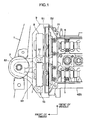
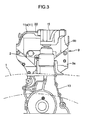
- FIGS. 1 to 12 show an engine front structure, according to an embodiment of the present invention.
- the engine is an inline four-cylinder transverse engine designed to be mounted on a vehicle body in such a manner that a crankshaft 3a thereof is oriented in a width direction (i.e., lateral direction) of the vehicle body.
- the engine is mounted in an engine compartment of a front of the vehicle body in a three-point mounting manner in such a way that a front end thereof is supported relative to a front frame 1 of the vehicle body by an engine mount 2 and a rear end thereof is supported by two mount portions (not shown) arranged in a longitudinal direction of the vehicle body.
- the engine is provided with an engine body B which has a cylinder block 3 and a cylinder head 4 disposed at a top of the cylinder bock 3.
- An intake camshaft 5 and an exhaust camshaft 6 are disposed in an upper portion of the cylinder head 4 and in parallel relation to each other.
- a camshaft driving force transmission mechanism (not shown) is arranged on the side of a front surface of the engine body B (corresponding to one longitudinal end of the crankshaft 3a) to transmit a driving force from the crankshaft 3a to each of the camshafts 5 and 6.
- Two solenoid-controlled type variable camshaft timing mechanisms 7 and 8 each incorporating a solenoid actuator are disposed at and associated with respective front ends of the intake and exhaust camshafts 5 and 6.
- Each of the variable camshaft timing mechanisms 7 and 8 has a conventional structure as disclosed in, for example, U.S. Patent Application Publication No. 20050132988 .
- a timing cover 9 is disposed in opposed relation to a front surface of the cylinder head 4 to cover the camshaft driving force transmission mechanism, and a casing cover 10 is disposed in opposed relation to a front surface of the cylinder block 3.
- the timing cover 9 and the casing cover 10 are fastened to the engine body B with a bolt so as to be assembled together. It is understood that these covers 9 and 10 may be integrally formed as a single component.
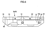
- the timing cover 9 has a cover body 9a which is opposed to the front surface of the cylinder head 4, and an upper extension portion 9b which extends upwardly from an upper portion of the cover body 9a and reaches a height position along a front edge of a cylinder head cover 11 disposed above the cylinder head 4.
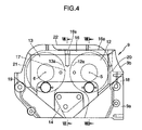
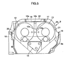
- the upper extension portion 9b has an inner surface, i.e., a surface on a rearward side of the engine, which is formed with two depressions 12 and 13 each formed to have an approximately circular shape and receive therein a corresponding one of the variable camshaft timing mechanisms 7 and 8 disposed at the respective front ends of the intake and exhaust camshafts 5 and 6.
- the cover body 9a has a fastening seat 14 in an approximately central region thereof.
- the fastening seat 14 is increased in wall thickness to have a relatively high stiffness, and fastened to the engine body B (cylinder head 4) with a bolt.
- the upper extension portion 9b has an engine-mounting-bracket receiving seat 16 extending from a central region to a right (in front view) end of a top surface thereof.
- the engine-mounting-bracket receiving seat 16 is increased in wall thickness to have a relatively high stiffness, and formed to have a seat surface 16a allowing an engine mounting bracket 15 to be fastened thereto at two positions with bolts.
- the upper extension portion 9b also has a connection portion 17 formed on a central region of the inner surface thereof in a width direction of the engine.
- the connection portion 17 is increased in wall thickness to have a relatively high stiffness.
- the upper extension portion 9b is formed to extend along the depressions 12 and 13 and connect between the fastening seat 14 and the engine-mounting-bracket receiving seat 16.
- the timing cover 9 has two flanges 18 and 19 provided along respective side edges of the timing cover 9 which are opposed to each other in the width direction of the engine, and fastened to the cylinder head 4 with bolts.
- the flange 18 (on the right side in front view) is formed to have a wall thickness greater than that of the flange 19 (on the left side in front view), i.e., have a stiffness greater than that of the flange 19, and connect with the engine-mounting-bracket receiving seat 16 through the upper extension portion 9b.
- Each of the depressions 12 and 13 receiving therein the respective variable camshaft timing mechanisms 7 and 8 has two side walls 20 and 21 located in opposed relation to each other in the width direction of the engine. Each of the side walls 20 and 21 is increased in wall thickness to have a relatively high stiffness, and formed to connect with the engine-mounting-bracket receiving seat 16.
- the top surface of the upper extension portion 9b is formed with a sealing edge 22 on the rearward side of the engine relative to the engine-mounting-bracket receiving seat 16 of the upper extension portion 9b, to allow a front edge 11a of the cylinder head cover 11 to be attached thereto along the engine-mounting-bracket receiving seat 16.
- the seat surface 16a of the engine-mounting-bracket receiving seat 16 is formed substantially flat.
- the connection portion 17 continuously extends from the top of the fastening seat 14 and extends continuously to the engine-mounting-bracket receiving seat 16.
- the engine-mounting-bracket receiving seat 16 and the connection portion 17 share the common side surfaces that are right & left circular shaped inner side surfaces 12a, 13a of the right and left depressions 12, 13 which receive therein said variable camshaft mechanism 7, 8.
- a cross sectional area of the side surfaces 12a, 13a taken along a horizontal line is substantially a filled rectangle from the lowermost of the depressions 12, 13 to the topmost of the depressions 12, 13, except a fastening hole 16s.
- connection portion 17 and the stiffness of the engine-mounting-bracket receiving seat 16 are made much higher than those corresponding elements of the timing cover with the structure where only a circumferential rib (or ribs) with a certain thickness is formed to surround the variable camshaft timing mechanisms 7, 8.
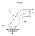
- the mounting bracket 15 has an upper fastening surface portion 51 which is fastened to the seat surface 16a of the timing cover 9 with a bolt, a lower fastening surface portion 52 which is fastened to the engine mount 2 with a bolt, and a connection portion 53 extending upward from the lower fastening surface portion 52 to the upper fastening surface portion 51.
- the upper fastening surface portion 51 is formed with two bolt holes 54 and 55 for bolting
- the lower fastening surface portion 52 is formed with one bolt hole 56 having a diameter greater than that of each of the bolt holes 54 and 55.
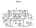
- the engine includes a frontmost camshaft bearing portion 31 which supports the camshafts 5 and 6 at a frontmost position of the cylinder head 4.
- the frontmost camshaft bearing portion 31 is in the form of upper and lower bearing members 32 and 33 respectively separatable from the cylinder head 4.
- Each of the upper and lower bearing members 32 and 33 is designed to rotatably support respective halves of the front ends of the intake and exhaust camshafts 5 and 6.
- the cylinder head 4 is formed with two fastening portions (bolt bosses) 34 and 35 at respective positions downwardly overlapping the frontmost camshaft bearing portion 31 to fasten the cylinder head 4 to the cylinder block 3 with bolts therethrough.
- the codes S1 and S2 indicate a sealing rubber which seals between the timing cover 9 and the cylinder head cover 11, and a sealing rubber which seals between the cylinder head 4 and the cylinder head cover 11, respectively.
- These sealing rubbers S1 and S2 are integrally formed as a single component.
- the present invention may be applied to various types of engines, for example, an engine equipped with a hydraulically-controlled type variable camshaft timing mechanism for an exhaust camshaft.
- a first aspect of the present invention relates to an engine front structure where an engine includes an engine body having a cylinder block and a cylinder head disposed at a top of the cylinder bock; intake and exhaust camshafts which are disposed in an upper portion of the cylinder head and in parallel relation to each other; and a variable camshaft timing mechanism provided at one end of at least the intake camshaft in the camshafts to controllably change a rotational phase of corresponding camshaft.
- the variable camshaft timing mechanism is located on the side of a front of the engine where a camshaft driving force transmission mechanism is arranged.
- the engine is also provided with a timing cover.
- the engine front structure is provided with: a cover body of the timing cover which covers the camshaft driving force transmission mechanism at a position opposed to a front surface of the cylinder head; an upper extension portion of the timing cover which extends upwardly from an upper portion of the cover body and has an inner surface formed with a depression receiving therein the variable camshaft timing mechanism; a fastening seat on the cover body with a relatively high stiffness which is located beneath of the upper extension portion and centrally in a width direction of the engine and is fastened to the engine body; an engine-mounting-bracket receiving seat which is formed on a top surface of the upper extension portion to have a relatively high stiffness and attached to an engine mounting bracket; and a connection portion which is provided on a central region of the inner surface of the upper extension portion in the width direction of the engine to extend along the depression and connect between the fastening seat and the engine-mounting-bracket receiving seat with a relatively high stiffness.
- the timing cover has two flanges which are provided along respective side edges of the timing cover to be attached to the cylinder head and are integrally connected with the engine-mounting-bracket receiving seat through the upper extension portion.
- one of the flanges is formed to have a stiffness greater than that of the other flange.
- variable camshaft timing mechanism is a solenoid-controlled type variable camshaft timing mechanism incorporating a solenoid actuator
- the upper extension portion of the timing cover has an overlapping region with the variable camshaft timing mechanism.
- the overlapping region is formed to be concaved forwardly relative to the front of the engine so as to define the depression receiving therein the variable camshaft timing mechanism in such a manner that the depression has two side walls located in opposed relation to each other in the width direction of the engine and each formed to have a relatively high stiffness and connect with the engine-mounting-bracket receiving seat.
- the engine is a transverse engine designed to be mounted and supported relative to a front frame of a vehicle body in such a manner that a crankshaft of the engine is oriented in a lateral direction of the vehicle body.
- a frontmost camshaft bearing portion which supports the camshafts at a frontmost position of the cylinder head.
- the frontmost camshaft bearing portion is in the form of upper and lower bearing members respectively separatable from the cylinder head.
- a fastening portion is formed with the cylinder head at a position beneath of the frontmost camshaft bearing portion to fasten the cylinder head to the cylinder block with a bolt therethrough.
- a cylinder head cover disposed above the cylinder head, and the top surface of the upper extension portion is formed with a sealing edge on a rearward side of the engine relative to the engine-mounting-bracket receiving seat of the upper extension portion, to allow a front edge of the cylinder head cover to be attached thereto along the engine-mounting-bracket receiving seat.
- a second aspect of the present invention relates to an engine front structure where an engine includes an engine body having a cylinder block and a cylinder head disposed at a top of the cylinder bock; intake and exhaust camshafts which are disposed in an upper portion of the cylinder head and in parallel relation to each other; and a variable camshaft timing mechanism provided at one end of at least the intake camshaft in the camshafts to controllably change a rotational phase of corresponding camshaft.
- the variable camshaft timing mechanism is located on the side of a front of the engine where a camshaft driving force transmission mechanism is arranged.
- the engine is also provided with a timing cover.
- the engine front structure is provided with: a cover body of the timing cover which covers the camshaft driving force transmission mechanism at a position opposed to a front surface of the cylinder head; an upper extension portion of the timing cover which extends upwardly from an upper portion of the cover body and has an inner surface formed with a depression receiving therein the variable camshaft timing mechanism; a fastening seat on the cover body with a relatively high stiffness which is located beneath of the upper extension portion and centrally in a width direction of the engine and is fastened to the engine body; an engine-mounting-bracket receiving seat which is formed on a top surface of the upper extension portion to have a relatively high stiffness and attached to an engine mounting bracket; and a connection portion which is provided on a central region of the inner surface of the upper extension portion in the width direction of the engine to extend along the depression and connect between the fastening seat and the engine-mounting-bracket receiving seat with a relatively high stiffness.
- the timing cover has two flanges which are provided along respective side edges of the timing cover to be attached to the cylinder head and are integrally connected with the engine-mounting-bracket receiving seat through the upper extension portion.
- one of the flanges is formed to have a stiffness greater than that of the other flange.
- One of the flanges is formed to have a stiffness greater than that of the other flange, and connect with the engine-mounting-bracket receiving seat through the upper extension portion.
- the engine is a transverse engine designed to be mounted and supported relative to a front frame of a vehicle body in such a manner that a crankshaft of the engine is oriented in a lateral direction of the vehicle body.
- a third aspect of the present invention relates to an engine front structure where an engine includes an engine body having a cylinder block and a cylinder head disposed at a top of the cylinder bock; intake and exhaust camshafts which are disposed in an upper portion of the cylinder head and in parallel relation to each other; and a variable camshaft timing mechanism provided at one end of at least the intake camshaft in the camshafts to controllably change a rotational phase of corresponding camshaft.
- the variable camshaft timing mechanism is located on the side of a front of the engine where a camshaft driving force transmission mechanism is arranged.
- the engine is also provided with a timing cover.
- the engine front structure is provided with: a cover body of the timing cover which covers the camshaft driving force transmission mechanism at a position opposed to a front surface of the cylinder head; an upper extension portion of the timing cover which extends upwardly from an upper portion of the cover body and has an inner surface formed with a depression receiving therein the variable camshaft timing mechanism; a fastening seat on the cover body with a relatively high stiffness which is located beneath of the upper extension portion and centrally in a width direction of the engine and is fastened to the engine body; an engine-mounting-bracket receiving seat which is formed on a top surface of the upper extension portion to have a relatively high stiffness and attached to an engine mounting bracket; and a connection portion which is provided on a central region of the inner surface of the upper extension portion in the width direction of the engine to extend along the depression and connect between the fastening seat and the engine-mounting-bracket receiving seat with a relatively high stiffness.
- the variable camshaft timing mechanism is a solenoid-controlled type variable camshaft timing mechanism incorporating a solenoid actuator.
- the upper extension portion of the timing cover has an overlapping region with the variable camshaft timing mechanism.
- the overlapping region is formed to be concaved forwardly relative to the front of the engine so as to define the depression receiving therein the variable camshaft timing mechanism in such a manner that the depression has two side walls located in opposed relation to each other in the width direction of the engine and each formed to have a relatively high stiffness and connect with the engine-mounting-bracket seat.
- the engine is a transverse engine designed to be mounted and supported relative to a front frame of a vehicle body in such a manner that a crankshaft of the engine is oriented in a lateral direction of the vehicle body.
Landscapes
- Engineering & Computer Science (AREA)
- Chemical & Material Sciences (AREA)
- Combustion & Propulsion (AREA)
- Mechanical Engineering (AREA)
- General Engineering & Computer Science (AREA)
- Transportation (AREA)
- Cylinder Crankcases Of Internal Combustion Engines (AREA)
- Valve-Gear Or Valve Arrangements (AREA)
- Arrangement Or Mounting Of Propulsion Units For Vehicles (AREA)
- Valve Device For Special Equipments (AREA)
Applications Claiming Priority (1)
| Application Number | Priority Date | Filing Date | Title |
|---|---|---|---|
| JP2006180779A JP4556921B2 (ja) | 2006-06-30 | 2006-06-30 | エンジンの前部構造 |
Publications (2)
| Publication Number | Publication Date |
|---|---|
| EP1873384A2 true EP1873384A2 (de) | 2008-01-02 |
| EP1873384A3 EP1873384A3 (de) | 2014-01-22 |
Family
ID=38481036
Family Applications (1)
| Application Number | Title | Priority Date | Filing Date |
|---|---|---|---|
| EP07111239.5A Withdrawn EP1873384A3 (de) | 2006-06-30 | 2007-06-28 | Vorderteilkonstruktion eines Motors |
Country Status (4)
| Country | Link |
|---|---|
| US (1) | US7581524B2 (de) |
| EP (1) | EP1873384A3 (de) |
| JP (1) | JP4556921B2 (de) |
| CN (1) | CN101096927B (de) |
Cited By (1)
| Publication number | Priority date | Publication date | Assignee | Title |
|---|---|---|---|---|
| FR2967098A1 (fr) * | 2010-11-08 | 2012-05-11 | Peugeot Citroen Automobiles Sa | Dispositif de maintien du moteur thermique d'un vehicule automobile |
Families Citing this family (6)
| Publication number | Priority date | Publication date | Assignee | Title |
|---|---|---|---|---|
| JP5845232B2 (ja) * | 2013-11-08 | 2016-01-20 | 本田技研工業株式会社 | 内燃機関のカバー取付構造 |
| US9566855B2 (en) | 2013-11-08 | 2017-02-14 | Honda Motor Co., Ltd. | Head cover structure of engine and suspension structure thereof |
| JP5845233B2 (ja) * | 2013-11-08 | 2016-01-20 | 本田技研工業株式会社 | エンジンのヘッドカバー構造及びその懸架構造 |
| US9610902B2 (en) * | 2014-03-19 | 2017-04-04 | GM Global Technology Operations LLC | Assembly with slip joint for fastening vehicle component and method of assembly |
| KR101608373B1 (ko) | 2014-06-27 | 2016-04-01 | 케이씨더블류 주식회사 | 와이퍼 블레이드 |
| JP6551200B2 (ja) * | 2015-12-02 | 2019-07-31 | スズキ株式会社 | 車両用内燃機関の支持装置 |
Family Cites Families (9)
| Publication number | Priority date | Publication date | Assignee | Title |
|---|---|---|---|---|
| JP2770632B2 (ja) * | 1992-01-27 | 1998-07-02 | 日産自動車株式会社 | エンジンのフロントカバー構造 |
| JPH09196283A (ja) | 1996-01-16 | 1997-07-29 | Yamaha Motor Co Ltd | 車両用エンジン装置 |
| FR2783876B1 (fr) * | 1998-09-24 | 2000-10-27 | Renault | Carter de distribution multipiece pour moteur a combustion interne |
| CN1229127A (zh) * | 1999-03-16 | 1999-09-22 | 贾全 | 一种高热值无烟煤 |
| JP3823786B2 (ja) * | 2001-09-11 | 2006-09-20 | 日産自動車株式会社 | V型内燃機関のマウントブラケット取付構造 |
| KR100445219B1 (ko) * | 2002-03-05 | 2004-08-21 | 지엠대우오토앤테크놀로지주식회사 | 자동차용 토크롤축 엔진마운팅 브라켓의 장착구조 |
| JP2005127219A (ja) * | 2003-10-23 | 2005-05-19 | Yamaha Motor Co Ltd | 4サイクルエンジン及び自動二輪車 |
| FR2862914B1 (fr) * | 2003-12-02 | 2006-02-10 | Renault Sas | Dispositif de support moteur |
| JP4321517B2 (ja) * | 2005-11-25 | 2009-08-26 | スズキ株式会社 | オイルコントロールバルブの取付け構造 |
-
2006
- 2006-06-30 JP JP2006180779A patent/JP4556921B2/ja not_active Expired - Fee Related
-
2007
- 2007-06-27 CN CN2007101279360A patent/CN101096927B/zh not_active Expired - Fee Related
- 2007-06-28 EP EP07111239.5A patent/EP1873384A3/de not_active Withdrawn
- 2007-06-29 US US11/771,042 patent/US7581524B2/en not_active Expired - Fee Related
Cited By (1)
| Publication number | Priority date | Publication date | Assignee | Title |
|---|---|---|---|---|
| FR2967098A1 (fr) * | 2010-11-08 | 2012-05-11 | Peugeot Citroen Automobiles Sa | Dispositif de maintien du moteur thermique d'un vehicule automobile |
Also Published As
| Publication number | Publication date |
|---|---|
| US20080105227A1 (en) | 2008-05-08 |
| JP4556921B2 (ja) | 2010-10-06 |
| US7581524B2 (en) | 2009-09-01 |
| JP2008008231A (ja) | 2008-01-17 |
| CN101096927B (zh) | 2011-06-29 |
| CN101096927A (zh) | 2008-01-02 |
| EP1873384A3 (de) | 2014-01-22 |
Similar Documents
| Publication | Publication Date | Title |
|---|---|---|
| US8584646B2 (en) | Chain case structure for engine | |
| US7581524B2 (en) | Engine front structure | |
| JP4001848B2 (ja) | エンジンの燃料分配管保護構造 | |
| US8161927B2 (en) | Valve system for overhead-camshaft-type internal combustion engine, and engine incorporating same | |
| US8857402B2 (en) | Engine with variable valve timing mechanism | |
| US10421347B2 (en) | Head cover structure of engine and suspension structure thereof | |
| EP1748168A2 (de) | Montagevorrichtung für Nockenwellenwinkelsensor | |
| JP5581438B2 (ja) | 内燃機関のヘッドカバー構造 | |
| JP5180951B2 (ja) | 内燃機関のタイミングトレーンカバー | |
| JP5115319B2 (ja) | 車載エンジン | |
| JP2009293574A (ja) | エンジンの上部構造 | |
| JP7383974B2 (ja) | エンジンのチェーンカバー構造 | |
| US7650862B2 (en) | Engine and motorcycle | |
| JP2021063490A (ja) | エンジンのチェーンカバー構造 | |
| JP4544100B2 (ja) | エンジンの前部構造 | |
| JP2009144726A (ja) | オイルコントロールバルブの取付け構造 | |
| JP3734218B2 (ja) | ベアリングキャップ構造 | |
| JP2006118512A (ja) | オイルコントロールバルブの取付け構造 | |
| JP7746828B2 (ja) | 内燃機関 | |
| JP5363639B2 (ja) | 内燃機関のタイミングトレーンカバー | |
| JP7395945B2 (ja) | エンジンのカバー構造 | |
| KR100391330B1 (ko) | 자동차의 오일 팬용 베드 플레이트 장착구조 | |
| EP1541848A1 (de) | Motor für motorroller | |
| JP2006002779A (ja) | ベアリングキャップ構造 | |
| JPH08312311A (ja) | V型エンジンのカム軸駆動装置 |
Legal Events
| Date | Code | Title | Description |
|---|---|---|---|
| PUAI | Public reference made under article 153(3) epc to a published international application that has entered the european phase |
Free format text: ORIGINAL CODE: 0009012 |
|
| AK | Designated contracting states |
Kind code of ref document: A2 Designated state(s): AT BE BG CH CY CZ DE DK EE ES FI FR GB GR HU IE IS IT LI LT LU LV MC MT NL PL PT RO SE SI SK TR |
|
| AX | Request for extension of the european patent |
Extension state: AL BA HR MK YU |
|
| PUAL | Search report despatched |
Free format text: ORIGINAL CODE: 0009013 |
|
| AK | Designated contracting states |
Kind code of ref document: A3 Designated state(s): AT BE BG CH CY CZ DE DK EE ES FI FR GB GR HU IE IS IT LI LT LU LV MC MT NL PL PT RO SE SI SK TR |
|
| AX | Request for extension of the european patent |
Extension state: AL BA HR MK RS |
|
| RIC1 | Information provided on ipc code assigned before grant |
Ipc: F02F 7/00 20060101AFI20131217BHEP |
|
| 17P | Request for examination filed |
Effective date: 20140715 |
|
| RBV | Designated contracting states (corrected) |
Designated state(s): AT BE BG CH CY CZ DE DK EE ES FI FR GB GR HU IE IS IT LI LT LU LV MC MT NL PL PT RO SE SI SK TR |
|
| AKX | Designation fees paid |
Designated state(s): DE |
|
| STAA | Information on the status of an ep patent application or granted ep patent |
Free format text: STATUS: THE APPLICATION HAS BEEN WITHDRAWN |
|
| 18W | Application withdrawn |
Effective date: 20160624 |