EP1864853A2 - Kopfstütze eines Fahrzeugsitzes mit Behältnis - Google Patents
Kopfstütze eines Fahrzeugsitzes mit Behältnis Download PDFInfo
- Publication number
- EP1864853A2 EP1864853A2 EP07008477A EP07008477A EP1864853A2 EP 1864853 A2 EP1864853 A2 EP 1864853A2 EP 07008477 A EP07008477 A EP 07008477A EP 07008477 A EP07008477 A EP 07008477A EP 1864853 A2 EP1864853 A2 EP 1864853A2
- Authority
- EP
- European Patent Office
- Prior art keywords
- container
- headrest
- recess
- wall
- housing
- Prior art date
- Legal status (The legal status is an assumption and is not a legal conclusion. Google has not performed a legal analysis and makes no representation as to the accuracy of the status listed.)
- Granted
Links
- 238000004140 cleaning Methods 0.000 description 2
- 239000006260 foam Substances 0.000 description 2
- 235000013305 food Nutrition 0.000 description 2
- 239000011521 glass Substances 0.000 description 2
- 230000001419 dependent effect Effects 0.000 description 1
- 230000000694 effects Effects 0.000 description 1
- 235000015110 jellies Nutrition 0.000 description 1
- 239000008274 jelly Substances 0.000 description 1
Images
Classifications
-
- B—PERFORMING OPERATIONS; TRANSPORTING
- B60—VEHICLES IN GENERAL
- B60R—VEHICLES, VEHICLE FITTINGS, OR VEHICLE PARTS, NOT OTHERWISE PROVIDED FOR
- B60R7/00—Stowing or holding appliances inside vehicle primarily intended for personal property smaller than suit-cases, e.g. travelling articles, or maps
- B60R7/04—Stowing or holding appliances inside vehicle primarily intended for personal property smaller than suit-cases, e.g. travelling articles, or maps in driver or passenger space, e.g. using racks
- B60R7/043—Stowing or holding appliances inside vehicle primarily intended for personal property smaller than suit-cases, e.g. travelling articles, or maps in driver or passenger space, e.g. using racks mounted on or under a seat
-
- B—PERFORMING OPERATIONS; TRANSPORTING
- B60—VEHICLES IN GENERAL
- B60N—SEATS SPECIALLY ADAPTED FOR VEHICLES; VEHICLE PASSENGER ACCOMMODATION NOT OTHERWISE PROVIDED FOR
- B60N2/00—Seats specially adapted for vehicles; Arrangement or mounting of seats in vehicles
- B60N2/80—Head-rests
- B60N2/806—Head-rests movable or adjustable
- B60N2/809—Head-rests movable or adjustable vertically slidable
-
- B—PERFORMING OPERATIONS; TRANSPORTING
- B60—VEHICLES IN GENERAL
- B60N—SEATS SPECIALLY ADAPTED FOR VEHICLES; VEHICLE PASSENGER ACCOMMODATION NOT OTHERWISE PROVIDED FOR
- B60N2/00—Seats specially adapted for vehicles; Arrangement or mounting of seats in vehicles
- B60N2/80—Head-rests
- B60N2/806—Head-rests movable or adjustable
- B60N2/838—Tiltable
-
- B—PERFORMING OPERATIONS; TRANSPORTING
- B60—VEHICLES IN GENERAL
- B60N—SEATS SPECIALLY ADAPTED FOR VEHICLES; VEHICLE PASSENGER ACCOMMODATION NOT OTHERWISE PROVIDED FOR
- B60N2/00—Seats specially adapted for vehicles; Arrangement or mounting of seats in vehicles
- B60N2/80—Head-rests
- B60N2/879—Head-rests with additional features not related to head-rest positioning, e.g. heating or cooling devices or loudspeakers
Definitions
- the invention relates to a headrest of a vehicle seat, with a trained in the rear region of the headrest, lockable recess.
- Such a headrest is from the DE 36 37 772 A1 known.
- a rear open housing is used, which has obliquely outwardly from the bottom side walls.
- the housing rests against the foam padded headrest. It is glued to the headrest or connected in some other way.
- the housing swivels on a mirror holder with vanity mirror on.
- a cover is provided, which is pivotally mounted about a formed at the upper edge of the housing, extending in the transverse direction axis and a locking mechanism in various angular positions in the region of the open position and the closed position.
- a headrest of a vehicle seat with a recess is further in the DE 100 29 624 A1 described.
- a housing is provided which can be closed by means of a lid, wherein this cover in a lower region of the housing about a transverse axis in a substantially horizontal End position is pivotable.
- the housing is used, for example, additionally the inclusion of a screen.
- the backrest of the vehicle seat is provided with a, but larger storage compartment, which is closed in a corresponding manner by means of a lid. This storage compartment serves to accommodate a keyboard.
- a headrest of a vehicle seat which serves to receive a make-up mirror.
- the headrest has a laterally accessible receptacle that receives the make-up mirror. In its withdrawn from the headrest position the make-up mirror is arranged laterally of the headrest.
- the object of the invention is to form a headrest of the type mentioned so that it is compact, but can still serve the placement of at least one object outside the actual headrest.
- the object is achieved in a headrest of the type mentioned in that the headrest in the recess serves to accommodate and store a foldable container, the container is open at the top, the container is arranged in its folded position substantially completely within the recess and closes the recess with a non-foldable wall, as well as the container in its unfolded position partially protrudes from the recess and in this position the receptacle of at least one object is used.
- the container In its folded position, the container is thus not intended to receive an item. Only when the container is unfolded does it serve the inclusion of the at least one object. In the folded position, the container is integrated into the headrest and thus forms virtually a unit with the headrest.
- the recess is preferably substantially parallelepiped-shaped and dimensioned in depth such that sufficient space remains in the recess to substantially completely receive the container in its folded position.
- the container In this folded position, the container may protrude slightly above the headrest so that it can be conveniently gripped to transfer it to the unfolded position.
- the non-foldable wall of the container in the folded position of the container is aligned with the outer contour of the headrest. In this case, the non-foldable wall passes through the recess. Adjacent to the non-foldable wall, a depression is provided in the headrest, for example, in order to be able to grip the unfoldable wall in order to unfold the container.
- the recess is substantially cuboid. Such a design allows the inclusion of a container in its outer contour substantially cuboidal.
- the recess may be formed directly in the headrest, or indirectly in this, for example in a housing inserted in the headrest.
- the container can be unfolded or collapsed by a parallel movement of the non-foldable wall.
- a curved folding movement take place in the sense of a pivoting movement.
- the folding mechanism can be realized in a particularly simple manner, if it is accordion-like effect.
- a concrete design of the container provides that this, based on the folded position of the container, parallel to the non-foldable wall has a further non-foldable wall which is releasably connectable to the recess, in particular latching connected.
- the container with a frame or a housing is releasably connectable, in particular by means of a clip connection connectable. This makes it possible to dismantle the container from the headrest and simply reconnect to it. This is particularly advantageous if the container is to be cleaned, for example, in a dishwasher present in the house.
- the invention thus provides additional storage space for passengers of a vehicle, in particular for the rear passengers, without restricting the freedom of movement of the passengers.
- This storage space is individually in size, by the folding mechanism, adjustable, or it can, if no storage space is desired, the container are folded together. In this case, the container is completely integrated in the headrest.
- the container is the space gain ago twice as large as, for example, in a tilt.
- the container provides additional storage space for small things of the passengers, such as glasses, writing utensils, food, such as gummy bears for the children, paper tissues. It can also serve as a garbage container.
- the container is easy to remove for cleaning. When it is not needed, it is moved to the folded position and adapts positively to the headrest.
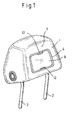
- a headrest 1 of a vehicle seat which receives two rods 2, in a known manner and Way in recesses of a backrest of the vehicle seat are latching plugged.
- the headrest 1 is therefore adjustable in height with respect to the backrest.
- the headrest 1 can also be adjusted in its inclination via unspecified means.
- the rear surface of the headrest 1, thus the surface of the headrest, which faces the rear passenger of the vehicle is designated by the reference numeral 3.
- the headrest 1 is provided with a recess which receives a housing 4 made of plastic.
- This housing 4 is formed open at the rear and has four side walls 6 directed slightly obliquely outwards from the bottom 5 of the housing 4.
- a recess 13 of the headrest 1 is still formed.
- the cup-shaped housing 4 is supported on the foam padded headrest 1.
- the side walls 4 are provided with projecting into the clear space of the housing 4 holding knobs 7.
- the housing 4 serves to receive a container 8 made of plastic, which is formed by two mutually parallel non-foldable walls 9 and 10 and a U-shaped, the two walls connecting intermediate part 11.
- This intermediate part 11 is an accordion element, thus can be folded.
- the two walls 9 and 10 are arranged close to each other, while in the unfolded position of the intermediate part 11, the walls 9 and 10 are placed at a greater distance from each other, so that the container 8, since it due to the U-shape of the intermediate part 11 is formed open at the top, can serve to receive one or more objects.
- the housing 4 has essentially the shape of a cuboid, taking into account the slightly obliquely arranged side walls 6.
- the wall 9 or wall 10 is formed substantially rectangular.
- the outer contour of the housing 4 facing wall 9 of the container 8 is so matched to the inner dimensions, based on the bottom 5 of the housing 4, that the wall 10, with inserted into the housing 4 container 8, the holding knobs 7 engages behind. As a result, the container 8 is connected to the housing 4 and thus the headrest 1.
- the other wall 9 thus the wall 5 facing away from the bottom of the container 8, substantially a plane with the surface 3 of the headrest 1 and is clamped between the side walls 6 of the housing 4.
- This clamping can be done by a vote of the dimensions of the wall 9 and housing 4 or by locking knobs on the wall, which engage in recesses of the housing 4.
- the wall 9 In order to take the wall 9 to open the container 8 low, the wall 9 is provided at the top and bottom with a concavity 12, in the area of which the wall 9 taken and this can be pulled away from the headrest 1 perpendicular to the surface 3.
- a concavity 12 By unfolding the container 8 - starting from the position of Figure 1 - results in the container 8, a relatively large storage space, which is suitable to accommodate various items, such as paper tissues, glasses, writing utensils, food, such as jelly babies for children.
- the container can serve to receive garbage.
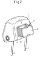
- the unfolded position of the container 8 is illustrated in FIG.
Landscapes
- Engineering & Computer Science (AREA)
- Mechanical Engineering (AREA)
- Aviation & Aerospace Engineering (AREA)
- Transportation (AREA)
- Vehicle Step Arrangements And Article Storage (AREA)
- Chair Legs, Seat Parts, And Backrests (AREA)
Abstract
Description
- Die Erfindung betrifft eine Kopfstütze eines Fahrzeugsitzes, mit einer im rückwärtigen Bereich der Kopfstütze ausgebildeten, verschließbaren Ausnehmung.
- Eine derartige Kopfstütze ist aus der
DE 36 37 772 A1 bekannt. In die Kopfstütze ist ein hinten offenes Gehäuse eingesetzt, das vom Boden schräg nach außen gerichtete Seitenwände aufweist. Das Gehäuse stützt sich an der schaumstoffgepolsterten Kopfstütze ab. Es ist mit der Kopfstütze verklebt oder auf andere Weise verbunden. Das Gehäuse nimmt schwenkbar einen Spiegelhalter mit Schminkspiegel auf. Zum Verschließen des Gehäuses ist ein Deckel vorgesehen, der um eine am oberen Rand des Gehäuses gebildete, in Querrichtung verlaufende Achse schwenkbar und über einen Rastmechanismus in verschiedenen Winkelstellungen im Bereich der Offenstellung und der Schließstellung ausreichend festgehalten wird. - Eine Kopfstütze eines Fahrzeugsitzes mit einer Ausnehmung ist ferner in der
DE 100 29 624 A1 beschrieben. Auch dort ist ein Gehäuse vorgesehen, das mittels eines Deckels verschließbar ist, wobei dieser Deckel in einem unteren Bereich des Gehäuses um eine quer verlaufende Achse in eine im Wesentlichen horizontale Endstellung schwenkbar ist. Das Gehäuse dient beispielsweise zusätzlich der Aufnahme eines Bildschirmes. Auch die Rückenlehne des Fahrzeugsitzes ist mit einem, allerdings größeren Staufach versehen, das in entsprechender Art und Weise mittels eines Deckels verschließbar ist. Dieses Staufach dient der Aufnahme einer Tastatur. - In der
DE 199 32 298 A1 ist eine Kopfstütze eines Fahrzeugsitzes beschrieben, die der Aufnahme eines Make-up-Spiegels dient. Die Kopfstütze weist eine seitlich zugängliche Aufnahme auf, die den Make-up-Spiegel aufnimmt. In seiner aus der Kopfstütze herausgezogenen Position ist der Make-up-Spiegel seitlich der Kopfstütze angeordnet. - Aufgabe der Erfindung ist es, eine Kopfstütze der eingangs genannten Art so weiter zu bilden, dass diese kompakt ausgebildet ist, aber dennoch der Unterbringung mindestens eines Gegenstandes außerhalb der eigentlichen Kopfstütze dienen kann.
- Gelöst wird die Aufgabe bei einer Kopfstütze der eingangs genannten Art dadurch, dass die Kopfstütze im Bereich der Ausnehmung der Aufnahme und Lagerung eines faltbaren Behältnisses dient, wobei das Behältnis oben offen ist, das Behältnis in seiner zusammengefalteten Stellung im wesentlichen vollständig innerhalb der Ausnehmung angeordnet ist und mit einer nicht faltbaren Wandung die Ausnehmung verschließt, sowie das Behältnis in seiner auseinander gefalteten Stellung teilweise aus der Ausnehmung ragt und in dieser Stellung der Aufnahme mindestens eines Gegenstandes dient.
- In seiner zusammengefalteten Stellung ist das Behältnis somit nicht dafür vorgesehen, einen Gegenstand aufzunehmen. Nur dann, wenn das Behältnis auseinandergefaltet ist, dient es der Aufnahme des mindestens einen Gegenstandes. In der zusammengefalteten Stellung ist das Behältnis in die Kopfstütze integriert und bildet damit quasi eine Einheit mit der Kopfstütze.
- Die Ausnehmung ist vorzugsweise im Wesentlichen quaderförmig ausgebildet und in der Tiefe derart dimensioniert, dass in der Ausnehmung ausreichend Platz verbleibt, das Behältnis in seiner zusammengefalteten Stellung im Wesentlichen vollständig aufzunehmen. In dieser zusammengefalteten Stellung kann das Behältnis geringfügig über die Kopfstütze hinausstehen, so dass es bequem ergriffen werden kann, um es in die auseinander gefaltete Stellung zu überführen. Es ist andererseits durchaus denkbar, dass die nicht faltbare Wandung des Behältnisses in der zusammengefalteten Stellung des Behältnisses mit der Außenkontur der Kopfstütze fluchtet. In diesem Fall durchsetzt die nicht faltbare Wandung die Ausnehmung. Benachbart der nicht faltbaren Wandung ist in der Kopfstütze beispielsweise eine Vertiefung vorgesehen, um die nicht faltbare Wandung zwecks Auseinanderfaltens des Behältnisses ergreifen zu können.
- Es wird als bevorzugt angesehen, wenn die Ausnehmung im Wesentlichen quaderförmig ausgebildet ist. Eine solche Gestaltung ermöglicht die Aufnahme eines in seiner Außenkontur im Wesentlichen quaderförmigen Behältnisses. Die Ausnehmung kann unmittelbar in der Kopfstütze gebildet sein, oder mittelbar in dieser, beispielsweise in einem in die Kopfstütze eingesetzten Gehäuse.
- Es wird als vorteilhaft angesehen, wenn das Behältnis durch eine parallele Bewegung der nicht faltbaren Wandung entfaltbar oder zusammenfaltbar ist. Grundsätzlich könnte statt der geradlinigen Auseinanderfalt- bzw. Zusammenfaltbewegung eine gekrümmte Faltbewegung im Sinne einer Schwenkbewegung stattfinden.
- Der Faltmechanismus lässt sich auf besonders einfache Art und Weise verwirklichen, wenn er ziehharmonikaartig wirksam ist.
- Eine konkrete Gestaltung des Behältnisses sieht vor, dass dieses, bezogen auf die zusammengefaltete Stellung des Behältnisses, parallel zur nicht faltbaren Wandung eine weitere nicht faltbare Wandung aufweist, die mit der Ausnehmung lösbar verbindbar, insbesondere rastierend verbindbar ist.
- Zweckmäßig ist das Behältnis mit einem Rahmen oder einem Gehäuse lösbar verbindbar, insbesondere mittels einer Clipsverbindung verbindbar. Dies ermöglicht es, das Behältnis von der Kopfstütze zu demontieren und einfach wieder mit dieser zu verbinden. Dies ist insbesondere dann von Vorteil, wenn das Behältnis gereinigt werden soll, beispielsweise in einer im Haus vorhandenen Spülmaschine.
- Die Erfindung bietet somit zusätzlichen Stauraum für Passagiere eines Fahrzeuges, insbesondere für die Fondpassagiere, ohne den Bewegungsfreiraum der Passagiere einzuschränken. Dieser Stauraum ist individuell in der Größe, durch den Faltmechanismus, einstellbar, oder es kann, wenn kein Stauraum gewünscht ist, das Behältnis zusammengefaltet werden. In diesem Fall ist das Behältnis vollständig in die Kopfstütze integriert. Insbesondere dann, wenn das Behältnis nicht um eine Achse ausgekippt, sondern durch eine geradlinige Bewegung ausgefaltet wird, ist das Behältnis vom Raumgewinn her doppelt so groß als zum Beispiel bei einer Kippung.
- Das Behältnis bietet zusätzlichen Stauraum für kleine Dinge der Passagiere, wie Brille, Schreibutensilien, Nahrungsmittel, beispielsweise Gummibärchen für die Kinder, Papiertaschentücher. Es kann auch als Müllbehälter dienen. Der Behälter lässt sich einfach zwecks Reinigung entnehmen. Wenn er nicht gebraucht wird, wird er in die zusammengefaltete Stellung überführt und passt sich formschlüssig der Kopfstütze an.
- Bevorzugte Weiterbildungen der Erfindung ergeben sich aus den abhängigen Unteransprüchen und der nachfolgenden Beschreibung.
- Nachfolgend wird ein Ausführungsbeispiel der Erfindung, ohne hierauf beschränkt zu sein, unter Bezugnahme auf die Zeichnungen näher erläutert. Die Zeichnung zeigt:
- Figur 1
- eine räumliche Ansicht der erfindungsgemäßen Kopfstütze mit Behältnis, schräg von hinten gesehen, in der zusammengefalteten Stellung des Behältnisses,
- Figur 2
- eine Ansicht gemäß Figur 1, veranschaulicht für die auseinander gefaltete Stellung des Behältnisses und
- Figur 3
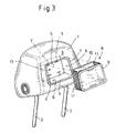
- eine Ansicht gemäß der Figuren 1 und 2, wobei die Kopfstütze und das aus dieser entnommene Behältnis, in nicht vollständig zusammengefalteter Stellung des Behältnisses, veranschaulicht ist.
- Veranschaulicht ist eine Kopfstütze 1 eines Fahrzeugsitzes, die zwei Stangen 2 aufnimmt, die in bekannter Art und Weise in Ausnehmungen einer Rückenlehne des Fahrzeugsitzes rastierend einsteckbar sind. Die Kopfstütze 1 ist demnach in der Höhe bezüglich der Rückenlehne verstellbar. Zusätzlich ist über nicht näher veranschaulichte Mittel die Kopfstütze 1 auch in ihrer Neigung verstellbar.
- Die rückwärtige Fläche der Kopfstütze 1, somit diejenige Fläche der Kopfstütze, die dem Fondpassagier des Fahrzeuges zugewandt ist, ist mit der Bezugsziffer 3 bezeichnet.
- Im Bereich der rückwärtigen Fläche 3 ist die Kopfstütze 1 mit einer Vertiefung versehen, die ein Gehäuse 4 aus Kunststoff aufnimmt. Dieses Gehäuse 4 ist hinten offen gebildet und weist vier vom Boden 5 des Gehäuses 4 geringfügig schräg nach außen gerichtete Seitenwände 6 auf. Im Gehäuse 4 ist dennoch eine Ausnehmung 13 der Kopfstütze 1 gebildet. Das schalenförmige Gehäuse 4 stützt sich an der schaumstoffgepolsterten Kopfstütze 1 ab. In Abstand zum Boden 5 sind die Seitenwände 4 mit in den lichten Raum des Gehäuses 4 vorspringenden Haltenoppen 7 versehen.
- Das Gehäuse 4 dient der Aufnahme eines Behältnisses 8 aus Kunststoff, das durch zwei parallel zueinander angeordnete nicht faltbare Wandungen 9 und 10 und ein U-förmiges, die beiden Wandungen verbindendes Zwischenteil 11 gebildet ist. Dieses Zwischenteil 11 ist ein Ziehharmonikaelement, lässt sich somit zusammenfalten. In der zusammengefalteten Position des Zwischenteils 11 sind die beiden Wandungen 9 und 10 nahe zueinander angeordnet, während in der auseinander gefalteten Stellung des Zwischenteils 11 die Wandungen 9 und 10 in größerem Abstand zueinander platziert sind, so dass das Behältnis 8 dann, da es aufgrund der U-Form des Zwischenteils 11 oben offen ausgebildet ist, der Aufnahme eines oder mehrerer Gegenstände dienen kann.
- Das Gehäuse 4 weist im Wesentlichen die Form eines Quaders auf, unter Berücksichtigung der geringfügig schräg angeordneten Seitenwände 6. Die Wandung 9 bzw. Wandung 10 ist im Wesentlichen rechteckig ausgebildet ist. Die äußere Kontur der dem Gehäuse 4 zugewandten Wandung 9 des Behältnisses 8 ist so auf die Innenabmessungen, bezogen auf den Boden 5 des Gehäuses 4 abgestimmt, dass die Wandung 10, bei in das Gehäuse 4 eingesetztem Behältnis 8, die Haltenoppen 7 hintergreift. Hierdurch ist das Behältnis 8 mit dem Gehäuse 4 und damit der Kopfstütze 1 verbunden.
- In zusammengefalteter Stellung des Behältnisses 8 bildet die andere Wandung 9, somit die dem Boden 5 abgewandte Wandung des Behältnisses 8, im wesentlichen eine Ebene mit der Fläche 3 der Kopfstütze 1 und ist klemmend zwischen den Seitenwänden 6 des Gehäuses 4 festgelegt. Diese Klemmung kann durch eine Abstimmung der Abmessungen von Wandung 9 und Gehäuse 4 oder aber durch Rastnoppen an der Wandung, die in Rastausnehmungen des Gehäuses 4 eingreifen, erfolgen.
- Um die Wandung 9 zum Öffnen des Behältnisses 8 günstig ergreifen zu können, ist die Wandung 9 oben und unten mit einer Einwölbung 12 versehen, im Bereich derer die Wandung 9 ergriffen und diese von der Kopfstütze 1 senkrecht zur Fläche 3 weggezogen werden kann. Durch das Auseinanderfalten des Behältnisses 8 - ausgehend von der Position nach Figur 1 - ergibt sich im Behältnis 8 ein relativ großer Stauraum, der geeignet ist, diverse Gegenstände aufzunehmen, zum Beispiel Papiertaschentücher, eine Brille, Schreibutensilien, Nahrungsmittel, wie Gummibärchen für Kinder. Andererseits kann das Behältnis der Aufnahme von Müll dienen. Die auseinander gefaltete Stellung des Behältnisses 8 ist in Figur 2 veranschaulicht.
- Ist das Behältnis 8 leer, kann es wieder zusammengefaltet werden, in die in Figur 1 gezeigte Ausgangsstellung.
- Um das Behältnis 8 zu reinigen, braucht es nur aus der Kopfstütze 1 entnommen werden. Es wird durch Ergreifen der Wandung 9 weiter herausgezogen, bis die Wandung 10 außer Eingriff mit den Haltenoppen 7 des Gehäuses gelangt. Nach dem Reinigen des Behältnisses 8 wird dieses einfach wieder in das Gehäuse 4 eingesteckt, in die in Figur 1 gezeigte Stellung, wobei durch Aufbringen des Drucks über die Wandung 9 und das Zwischenteil 11 auf die Wandung 10 diese Wandung 10 in Hintergriff mit den Haltenoppen 7 des Gehäuses 4 gelangt.
-
- Kopfstütze
- 1
- Stange
- 2
- Fläche
- 3
- Gehäuse
- 4
- Boden
- 5
- Seitenwand
- 6
- Haltenoppen
- 7
- Behältnis
- 8
- Wandung
- 9
- Wandung
- 10
- Zwischenteil
- 11
- Einwölbung
- 12
- Ausnehmung
- 13
Claims (7)
- Kopfstütze (1) eines Fahrzeugsitzes, mit einer im rückwärtigen Bereich der Kopfstütze (1) ausgebildeten, verschließbaren Ausnehmung (13), dadurch gekennzeichnet, dass die Kopfstütze (1) im Bereich der Ausnehmung (13) der Aufnahme und Lagerung eines faltbaren Behältnisses (8) dient, wobei das Behältnis (8) oben offen ist, das Behältnis (8) in seiner zusammengefalteten Stellung im wesentlichen vollständig innerhalb der Ausnehmung (13) angeordnet ist und mit einer nicht faltbaren Wandung (9) die Ausnehmung (13) verschließt, sowie das Behältnis (8) in seiner auseinander gefalteten Stellung teilweise aus der Ausnehmung (13) ragt und in dieser Stellung der Aufnahme mindestens eines Gegenstands dient.
- Kopfstütze nach Anspruch 1, dadurch gekennzeichnet, dass die Ausnehmung (13) im Wesentlichen quaderförmig ausgebildet ist.
- Kopfstütze nach Anspruch 1 oder 2, dadurch gekennzeichnet, dass das Behältnis (4) durch eine parallele Bewegung der nicht faltbaren Wandung (9) entfaltbar oder zusammenfaltbar ist.
- Kopfstütze nach einem der Ansprüche 1 bis 3, dadurch gekennzeichnet, dass die nicht faltbare Wandung (9) in der zusammengefalteten Stellung des Behältnisses (8) im Wesentlichen eine Ebene mit der Außenfläche (3) der Kopfstütze bildet.
- Kopfstütze nach einem der Ansprüche 1 bis 4, dadurch gekennzeichnet, dass das Behältnis (8), bezogen auf die zusammengefaltete Stellung des Behältnisses (8), parallel zur nicht faltbaren Wandung (9) eine weitere, nicht faltbare Wandung (10) aufweist, die mit der Kopfstütze (1) lösbar verbindbar, insbesondere rastierend verbindbar ist.
- Kopfstütze nach einem der Ansprüche 1 bis 5, dadurch gekennzeichnet, dass das Behältnis (8) mit einem Gehäuse (4) oder einem Rahmen der Kopfstütze lösbar verbindbar, insbesondere mittels einer Clipsverbindung verbindbar ist.
- Kopfstütze nach einem der Ansprüche 1 bis 6, dadurch gekennzeichnet, dass das Behältnis (8) aus Kunststoff besteht.
Applications Claiming Priority (1)
| Application Number | Priority Date | Filing Date | Title |
|---|---|---|---|
| DE102006026840A DE102006026840A1 (de) | 2006-06-09 | 2006-06-09 | Kopfstütze eines Fahrzeugsitzes mit Behältnis |
Publications (3)
| Publication Number | Publication Date |
|---|---|
| EP1864853A2 true EP1864853A2 (de) | 2007-12-12 |
| EP1864853A3 EP1864853A3 (de) | 2009-03-25 |
| EP1864853B1 EP1864853B1 (de) | 2012-09-12 |
Family
ID=38544330
Family Applications (1)
| Application Number | Title | Priority Date | Filing Date |
|---|---|---|---|
| EP07008477A Not-in-force EP1864853B1 (de) | 2006-06-09 | 2007-04-26 | Kopfstütze eines Fahrzeugsitzes mit Behältnis |
Country Status (2)
| Country | Link |
|---|---|
| EP (1) | EP1864853B1 (de) |
| DE (1) | DE102006026840A1 (de) |
Cited By (3)
| Publication number | Priority date | Publication date | Assignee | Title |
|---|---|---|---|---|
| WO2010067213A1 (en) * | 2008-12-11 | 2010-06-17 | Basicnet S.P.A. | Container for accommodating a foldable element in an automobile cockpit |
| CN107963006A (zh) * | 2017-11-25 | 2018-04-27 | 泰姆勒汽车部件(苏州)有限公司 | 房车座椅 |
| DE102018205805A1 (de) | 2018-04-17 | 2019-10-17 | Audi Ag | Vorrichtung für einen Sitz |
Families Citing this family (4)
| Publication number | Priority date | Publication date | Assignee | Title |
|---|---|---|---|---|
| DE102009021654A1 (de) * | 2009-05-16 | 2010-11-18 | GM Global Technology Operations, Inc., Detroit | Fahrzeugsitz |
| US9283876B2 (en) | 2012-03-02 | 2016-03-15 | GM Global Technology Operations LLC | Head restraint with storage |
| US9421916B1 (en) | 2015-05-05 | 2016-08-23 | GM Global Technology Operations LLC | Vehicle with collapsible silicone storage bins |
| DE102021214428A1 (de) | 2021-12-15 | 2023-06-15 | Psa Automobiles Sa | Kopfstütze für eine Rückenlehne eines Fahrzeugsitzes, Rückenlehnenanordnung für einen Fahrzeugsitz, Fahrzeugsitz mit der Rückenlehnenanordnung und Fahrzeug mit dem Fahrzeugsitz |
Citations (3)
| Publication number | Priority date | Publication date | Assignee | Title |
|---|---|---|---|---|
| DE3637772A1 (de) | 1986-11-06 | 1988-05-11 | Bayerische Motoren Werke Ag | Schminkspiegel an der rueckseite eines sitzes |
| DE19932298A1 (de) | 1998-07-16 | 2000-01-20 | Volkswagen Ag | Kopfstütze mit Make-up-Spiegel |
| DE10029624A1 (de) | 2000-06-20 | 2002-01-03 | Volkswagen Ag | Rückenlehne und Kopfstütze eines Fahrzeugsitzes |
Family Cites Families (6)
| Publication number | Priority date | Publication date | Assignee | Title |
|---|---|---|---|---|
| DE7105089U (de) * | 1972-06-22 | Metz C Gmbh | Vorrichtung zur Führung und/oder Festlegung eines pendelnd aufgehängten Arbeits- und/oder Rettungskorbes | |
| DE7006769U (de) * | 1970-02-25 | 1970-07-02 | Ebel Hubert | Mit einem autositz vereinigbare kopf- und nackenstuetze. |
| DE3409097A1 (de) * | 1984-03-13 | 1984-11-29 | Harri 5600 Wuppertal Thürer | Kopfstuetze mit integrierten erste-hilfe-verbandskasten oder paeckchen fuer automobilsitzlehnen |
| US5628543A (en) * | 1995-09-27 | 1997-05-13 | Hoover Universal, Inc. | Vehicle seat back having ski tote bag and trunk pass through |
| US5795005A (en) * | 1996-11-12 | 1998-08-18 | Prince Corporation | Folding storage compartment |
| DE102004016255B8 (de) * | 2004-04-02 | 2005-12-15 | Itw Automotive Products Gmbh & Co. Kg | Kopfstütze für die Vordersitze von Automobilen |
-
2006
- 2006-06-09 DE DE102006026840A patent/DE102006026840A1/de not_active Withdrawn
-
2007
- 2007-04-26 EP EP07008477A patent/EP1864853B1/de not_active Not-in-force
Patent Citations (3)
| Publication number | Priority date | Publication date | Assignee | Title |
|---|---|---|---|---|
| DE3637772A1 (de) | 1986-11-06 | 1988-05-11 | Bayerische Motoren Werke Ag | Schminkspiegel an der rueckseite eines sitzes |
| DE19932298A1 (de) | 1998-07-16 | 2000-01-20 | Volkswagen Ag | Kopfstütze mit Make-up-Spiegel |
| DE10029624A1 (de) | 2000-06-20 | 2002-01-03 | Volkswagen Ag | Rückenlehne und Kopfstütze eines Fahrzeugsitzes |
Cited By (3)
| Publication number | Priority date | Publication date | Assignee | Title |
|---|---|---|---|---|
| WO2010067213A1 (en) * | 2008-12-11 | 2010-06-17 | Basicnet S.P.A. | Container for accommodating a foldable element in an automobile cockpit |
| CN107963006A (zh) * | 2017-11-25 | 2018-04-27 | 泰姆勒汽车部件(苏州)有限公司 | 房车座椅 |
| DE102018205805A1 (de) | 2018-04-17 | 2019-10-17 | Audi Ag | Vorrichtung für einen Sitz |
Also Published As
| Publication number | Publication date |
|---|---|
| DE102006026840A1 (de) | 2007-12-13 |
| EP1864853B1 (de) | 2012-09-12 |
| EP1864853A3 (de) | 2009-03-25 |
Similar Documents
| Publication | Publication Date | Title |
|---|---|---|
| EP1864853B1 (de) | Kopfstütze eines Fahrzeugsitzes mit Behältnis | |
| DE102011075070A1 (de) | Halter für einen Getränkebehälter | |
| DE102009030577A1 (de) | Konsole eines Kraftfahrzeugs mit einem Behältnis zur Aufnahme eines Gegenstandes | |
| DE202012100251U1 (de) | Klapptisch | |
| DE102007001942B4 (de) | Umgestaltbare Sonnenblende | |
| DE4313525A1 (de) | Sonnenblende für Fahrzeuge | |
| DE102008018195A1 (de) | Sitz für ein Fahrzeug | |
| EP1683719A1 (de) | Tischeinheit für einen Sitz | |
| DE102010050178A1 (de) | Staufach für einen Kraftwagen | |
| DE20112066U1 (de) | Sitzanordnung | |
| EP2954799A1 (de) | Kofferschale oder Koffer mit integrierter Ablageeinrichtung sowie Herstellungsverfahren | |
| DE19844805A1 (de) | Tisch für ein Fahrzeug | |
| DE19817667C2 (de) | Aufbewahrungs- und Transportkiste für Bücher mit integrierter Buchstütze | |
| DE102018215315A1 (de) | Klappsitzanordnung mit integrierter Kofferablage für ein Schienenfahrzeug | |
| DE202017105766U1 (de) | Wandhalterung | |
| DE102009030890A1 (de) | Vorrichtung zum Anbringen an einem Fahrzeugsitzteil | |
| DE112008003006B4 (de) | Klappbarer Flaschentransportbehälter | |
| DE10120482B4 (de) | Vorrichtung für die Halterung von Getränkebehältern im Innenraum eines Kraftfahrzeugs | |
| DE602006000390T2 (de) | Hintere schwenkbare Abdeckplatte eines Kraftfahrzeugs | |
| DE10300358A1 (de) | Fahrzeugsitz mit Kleiderbügel | |
| DE102006049199A1 (de) | Aufbewahrungsanordnung für ein Fahrzeug | |
| DE1532639C (de) | Halterungsvorrichtung für Flaschen | |
| EP3150087B1 (de) | Sitzmöbel mit einer verstauvorrichtung | |
| DE102020213710A1 (de) | Ablagefach für ein fahrzeug | |
| DE202019103987U1 (de) | Klappbarer Buffettisch |
Legal Events
| Date | Code | Title | Description |
|---|---|---|---|
| PUAI | Public reference made under article 153(3) epc to a published international application that has entered the european phase |
Free format text: ORIGINAL CODE: 0009012 |
|
| AK | Designated contracting states |
Kind code of ref document: A2 Designated state(s): AT BE BG CH CY CZ DE DK EE ES FI FR GB GR HU IE IS IT LI LT LU LV MC MT NL PL PT RO SE SI SK TR |
|
| AX | Request for extension of the european patent |
Extension state: AL BA HR MK YU |
|
| PUAL | Search report despatched |
Free format text: ORIGINAL CODE: 0009013 |
|
| AK | Designated contracting states |
Kind code of ref document: A3 Designated state(s): AT BE BG CH CY CZ DE DK EE ES FI FR GB GR HU IE IS IT LI LT LU LV MC MT NL PL PT RO SE SI SK TR |
|
| AX | Request for extension of the european patent |
Extension state: AL BA HR MK RS |
|
| 17P | Request for examination filed |
Effective date: 20090925 |
|
| 17Q | First examination report despatched |
Effective date: 20091027 |
|
| AKX | Designation fees paid |
Designated state(s): AT BE BG CH CY CZ DE DK EE ES FI FR GB GR HU IE IS IT LI LT LU LV MC MT NL PL PT RO SE SI SK TR |
|
| RAP1 | Party data changed (applicant data changed or rights of an application transferred) |
Owner name: GM GLOBAL TECHNOLOGY OPERATIONS LLC |
|
| GRAP | Despatch of communication of intention to grant a patent |
Free format text: ORIGINAL CODE: EPIDOSNIGR1 |
|
| GRAS | Grant fee paid |
Free format text: ORIGINAL CODE: EPIDOSNIGR3 |
|
| GRAA | (expected) grant |
Free format text: ORIGINAL CODE: 0009210 |
|
| AK | Designated contracting states |
Kind code of ref document: B1 Designated state(s): AT BE BG CH CY CZ DE DK EE ES FI FR GB GR HU IE IS IT LI LT LU LV MC MT NL PL PT RO SE SI SK TR |
|
| REG | Reference to a national code |
Ref country code: GB Ref legal event code: FG4D Free format text: NOT ENGLISH |
|
| REG | Reference to a national code |
Ref country code: CH Ref legal event code: EP |
|
| REG | Reference to a national code |
Ref country code: AT Ref legal event code: REF Ref document number: 574897 Country of ref document: AT Kind code of ref document: T Effective date: 20120915 |
|
| REG | Reference to a national code |
Ref country code: IE Ref legal event code: FG4D Free format text: LANGUAGE OF EP DOCUMENT: GERMAN |
|
| REG | Reference to a national code |
Ref country code: DE Ref legal event code: R096 Ref document number: 502007010519 Country of ref document: DE Effective date: 20121108 |
|
| PG25 | Lapsed in a contracting state [announced via postgrant information from national office to epo] |
Ref country code: LT Free format text: LAPSE BECAUSE OF FAILURE TO SUBMIT A TRANSLATION OF THE DESCRIPTION OR TO PAY THE FEE WITHIN THE PRESCRIBED TIME-LIMIT Effective date: 20120912 Ref country code: CY Free format text: LAPSE BECAUSE OF FAILURE TO SUBMIT A TRANSLATION OF THE DESCRIPTION OR TO PAY THE FEE WITHIN THE PRESCRIBED TIME-LIMIT Effective date: 20120912 Ref country code: FI Free format text: LAPSE BECAUSE OF FAILURE TO SUBMIT A TRANSLATION OF THE DESCRIPTION OR TO PAY THE FEE WITHIN THE PRESCRIBED TIME-LIMIT Effective date: 20120912 |
|
| REG | Reference to a national code |
Ref country code: NL Ref legal event code: VDEP Effective date: 20120912 |
|
| REG | Reference to a national code |
Ref country code: LT Ref legal event code: MG4D Effective date: 20120912 |
|
| PG25 | Lapsed in a contracting state [announced via postgrant information from national office to epo] |
Ref country code: GR Free format text: LAPSE BECAUSE OF FAILURE TO SUBMIT A TRANSLATION OF THE DESCRIPTION OR TO PAY THE FEE WITHIN THE PRESCRIBED TIME-LIMIT Effective date: 20121213 Ref country code: LV Free format text: LAPSE BECAUSE OF FAILURE TO SUBMIT A TRANSLATION OF THE DESCRIPTION OR TO PAY THE FEE WITHIN THE PRESCRIBED TIME-LIMIT Effective date: 20120912 Ref country code: SI Free format text: LAPSE BECAUSE OF FAILURE TO SUBMIT A TRANSLATION OF THE DESCRIPTION OR TO PAY THE FEE WITHIN THE PRESCRIBED TIME-LIMIT Effective date: 20120912 Ref country code: SE Free format text: LAPSE BECAUSE OF FAILURE TO SUBMIT A TRANSLATION OF THE DESCRIPTION OR TO PAY THE FEE WITHIN THE PRESCRIBED TIME-LIMIT Effective date: 20120912 |
|
| PG25 | Lapsed in a contracting state [announced via postgrant information from national office to epo] |
Ref country code: ES Free format text: LAPSE BECAUSE OF FAILURE TO SUBMIT A TRANSLATION OF THE DESCRIPTION OR TO PAY THE FEE WITHIN THE PRESCRIBED TIME-LIMIT Effective date: 20121223 Ref country code: RO Free format text: LAPSE BECAUSE OF FAILURE TO SUBMIT A TRANSLATION OF THE DESCRIPTION OR TO PAY THE FEE WITHIN THE PRESCRIBED TIME-LIMIT Effective date: 20120912 Ref country code: EE Free format text: LAPSE BECAUSE OF FAILURE TO SUBMIT A TRANSLATION OF THE DESCRIPTION OR TO PAY THE FEE WITHIN THE PRESCRIBED TIME-LIMIT Effective date: 20120912 Ref country code: IS Free format text: LAPSE BECAUSE OF FAILURE TO SUBMIT A TRANSLATION OF THE DESCRIPTION OR TO PAY THE FEE WITHIN THE PRESCRIBED TIME-LIMIT Effective date: 20130112 Ref country code: NL Free format text: LAPSE BECAUSE OF FAILURE TO SUBMIT A TRANSLATION OF THE DESCRIPTION OR TO PAY THE FEE WITHIN THE PRESCRIBED TIME-LIMIT Effective date: 20120912 Ref country code: CZ Free format text: LAPSE BECAUSE OF FAILURE TO SUBMIT A TRANSLATION OF THE DESCRIPTION OR TO PAY THE FEE WITHIN THE PRESCRIBED TIME-LIMIT Effective date: 20120912 |
|
| PG25 | Lapsed in a contracting state [announced via postgrant information from national office to epo] |
Ref country code: PL Free format text: LAPSE BECAUSE OF FAILURE TO SUBMIT A TRANSLATION OF THE DESCRIPTION OR TO PAY THE FEE WITHIN THE PRESCRIBED TIME-LIMIT Effective date: 20120912 Ref country code: SK Free format text: LAPSE BECAUSE OF FAILURE TO SUBMIT A TRANSLATION OF THE DESCRIPTION OR TO PAY THE FEE WITHIN THE PRESCRIBED TIME-LIMIT Effective date: 20120912 Ref country code: PT Free format text: LAPSE BECAUSE OF FAILURE TO SUBMIT A TRANSLATION OF THE DESCRIPTION OR TO PAY THE FEE WITHIN THE PRESCRIBED TIME-LIMIT Effective date: 20130114 |
|
| PLBE | No opposition filed within time limit |
Free format text: ORIGINAL CODE: 0009261 |
|
| STAA | Information on the status of an ep patent application or granted ep patent |
Free format text: STATUS: NO OPPOSITION FILED WITHIN TIME LIMIT |
|
| PG25 | Lapsed in a contracting state [announced via postgrant information from national office to epo] |
Ref country code: BG Free format text: LAPSE BECAUSE OF FAILURE TO SUBMIT A TRANSLATION OF THE DESCRIPTION OR TO PAY THE FEE WITHIN THE PRESCRIBED TIME-LIMIT Effective date: 20121212 Ref country code: DK Free format text: LAPSE BECAUSE OF FAILURE TO SUBMIT A TRANSLATION OF THE DESCRIPTION OR TO PAY THE FEE WITHIN THE PRESCRIBED TIME-LIMIT Effective date: 20120912 |
|
| PGFP | Annual fee paid to national office [announced via postgrant information from national office to epo] |
Ref country code: GB Payment date: 20130424 Year of fee payment: 7 Ref country code: DE Payment date: 20130508 Year of fee payment: 7 |
|
| 26N | No opposition filed |
Effective date: 20130613 |
|
| PG25 | Lapsed in a contracting state [announced via postgrant information from national office to epo] |
Ref country code: IT Free format text: LAPSE BECAUSE OF FAILURE TO SUBMIT A TRANSLATION OF THE DESCRIPTION OR TO PAY THE FEE WITHIN THE PRESCRIBED TIME-LIMIT Effective date: 20120912 |
|
| PGFP | Annual fee paid to national office [announced via postgrant information from national office to epo] |
Ref country code: FR Payment date: 20130625 Year of fee payment: 7 |
|
| REG | Reference to a national code |
Ref country code: DE Ref legal event code: R097 Ref document number: 502007010519 Country of ref document: DE Effective date: 20130613 |
|
| BERE | Be: lapsed |
Owner name: GM GLOBAL TECHNOLOGY OPERATIONS LLC Effective date: 20130430 |
|
| PG25 | Lapsed in a contracting state [announced via postgrant information from national office to epo] |
Ref country code: MC Free format text: LAPSE BECAUSE OF FAILURE TO SUBMIT A TRANSLATION OF THE DESCRIPTION OR TO PAY THE FEE WITHIN THE PRESCRIBED TIME-LIMIT Effective date: 20120912 |
|
| REG | Reference to a national code |
Ref country code: CH Ref legal event code: PL |
|
| REG | Reference to a national code |
Ref country code: IE Ref legal event code: MM4A |
|
| PG25 | Lapsed in a contracting state [announced via postgrant information from national office to epo] |
Ref country code: LI Free format text: LAPSE BECAUSE OF NON-PAYMENT OF DUE FEES Effective date: 20130430 Ref country code: CH Free format text: LAPSE BECAUSE OF NON-PAYMENT OF DUE FEES Effective date: 20130430 Ref country code: BE Free format text: LAPSE BECAUSE OF NON-PAYMENT OF DUE FEES Effective date: 20130430 |
|
| PG25 | Lapsed in a contracting state [announced via postgrant information from national office to epo] |
Ref country code: IE Free format text: LAPSE BECAUSE OF NON-PAYMENT OF DUE FEES Effective date: 20130426 |
|
| REG | Reference to a national code |
Ref country code: AT Ref legal event code: MM01 Ref document number: 574897 Country of ref document: AT Kind code of ref document: T Effective date: 20130426 |
|
| PG25 | Lapsed in a contracting state [announced via postgrant information from national office to epo] |
Ref country code: AT Free format text: LAPSE BECAUSE OF NON-PAYMENT OF DUE FEES Effective date: 20130426 |
|
| REG | Reference to a national code |
Ref country code: DE Ref legal event code: R119 Ref document number: 502007010519 Country of ref document: DE |
|
| GBPC | Gb: european patent ceased through non-payment of renewal fee |
Effective date: 20140426 |
|
| REG | Reference to a national code |
Ref country code: FR Ref legal event code: ST Effective date: 20141231 |
|
| REG | Reference to a national code |
Ref country code: DE Ref legal event code: R119 Ref document number: 502007010519 Country of ref document: DE Effective date: 20141101 |
|
| PG25 | Lapsed in a contracting state [announced via postgrant information from national office to epo] |
Ref country code: DE Free format text: LAPSE BECAUSE OF NON-PAYMENT OF DUE FEES Effective date: 20141101 Ref country code: GB Free format text: LAPSE BECAUSE OF NON-PAYMENT OF DUE FEES Effective date: 20140426 |
|
| PG25 | Lapsed in a contracting state [announced via postgrant information from national office to epo] |
Ref country code: MT Free format text: LAPSE BECAUSE OF FAILURE TO SUBMIT A TRANSLATION OF THE DESCRIPTION OR TO PAY THE FEE WITHIN THE PRESCRIBED TIME-LIMIT Effective date: 20120912 Ref country code: FR Free format text: LAPSE BECAUSE OF NON-PAYMENT OF DUE FEES Effective date: 20140430 |
|
| PG25 | Lapsed in a contracting state [announced via postgrant information from national office to epo] |
Ref country code: TR Free format text: LAPSE BECAUSE OF FAILURE TO SUBMIT A TRANSLATION OF THE DESCRIPTION OR TO PAY THE FEE WITHIN THE PRESCRIBED TIME-LIMIT Effective date: 20120912 |
|
| PG25 | Lapsed in a contracting state [announced via postgrant information from national office to epo] |
Ref country code: LU Free format text: LAPSE BECAUSE OF NON-PAYMENT OF DUE FEES Effective date: 20130426 Ref country code: HU Free format text: LAPSE BECAUSE OF FAILURE TO SUBMIT A TRANSLATION OF THE DESCRIPTION OR TO PAY THE FEE WITHIN THE PRESCRIBED TIME-LIMIT; INVALID AB INITIO Effective date: 20070426 |