EP1861176B1 - Servicefreundliches ventil für brandbekämpfungssysteme - Google Patents
Servicefreundliches ventil für brandbekämpfungssysteme Download PDFInfo
- Publication number
- EP1861176B1 EP1861176B1 EP20060725168 EP06725168A EP1861176B1 EP 1861176 B1 EP1861176 B1 EP 1861176B1 EP 20060725168 EP20060725168 EP 20060725168 EP 06725168 A EP06725168 A EP 06725168A EP 1861176 B1 EP1861176 B1 EP 1861176B1
- Authority
- EP
- European Patent Office
- Prior art keywords
- valve
- locking means
- extinguishing fluid
- supply line
- closed position
- Prior art date
- Legal status (The legal status is an assumption and is not a legal conclusion. Google has not performed a legal analysis and makes no representation as to the accuracy of the status listed.)
- Active
Links
- 238000012423 maintenance Methods 0.000 title claims abstract description 32
- 239000012530 fluid Substances 0.000 claims abstract description 57
- 230000000903 blocking effect Effects 0.000 description 9
- 230000003068 static effect Effects 0.000 description 5
- 230000007797 corrosion Effects 0.000 description 3
- 238000005260 corrosion Methods 0.000 description 3
- 239000003595 mist Substances 0.000 description 3
- 238000010791 quenching Methods 0.000 description 3
- 238000012544 monitoring process Methods 0.000 description 2
- 230000004913 activation Effects 0.000 description 1
- 230000006378 damage Effects 0.000 description 1
- 230000001627 detrimental effect Effects 0.000 description 1
- 238000005553 drilling Methods 0.000 description 1
- 230000006870 function Effects 0.000 description 1
- 230000007257 malfunction Effects 0.000 description 1
- 230000007659 motor function Effects 0.000 description 1
- 230000000171 quenching effect Effects 0.000 description 1
- 230000000717 retained effect Effects 0.000 description 1
- 239000007921 spray Substances 0.000 description 1
Images


Classifications
-
- F—MECHANICAL ENGINEERING; LIGHTING; HEATING; WEAPONS; BLASTING
- F16—ENGINEERING ELEMENTS AND UNITS; GENERAL MEASURES FOR PRODUCING AND MAINTAINING EFFECTIVE FUNCTIONING OF MACHINES OR INSTALLATIONS; THERMAL INSULATION IN GENERAL
- F16K—VALVES; TAPS; COCKS; ACTUATING-FLOATS; DEVICES FOR VENTING OR AERATING
- F16K5/00—Plug valves; Taps or cocks comprising only cut-off apparatus having at least one of the sealing faces shaped as a more or less complete surface of a solid of revolution, the opening and closing movement being predominantly rotary
- F16K5/06—Plug valves; Taps or cocks comprising only cut-off apparatus having at least one of the sealing faces shaped as a more or less complete surface of a solid of revolution, the opening and closing movement being predominantly rotary with plugs having spherical surfaces; Packings therefor
- F16K5/0605—Plug valves; Taps or cocks comprising only cut-off apparatus having at least one of the sealing faces shaped as a more or less complete surface of a solid of revolution, the opening and closing movement being predominantly rotary with plugs having spherical surfaces; Packings therefor with particular plug arrangements, e.g. particular shape or built-in means
-
- A—HUMAN NECESSITIES
- A62—LIFE-SAVING; FIRE-FIGHTING
- A62C—FIRE-FIGHTING
- A62C35/00—Permanently-installed equipment
- A62C35/58—Pipe-line systems
- A62C35/68—Details, e.g. of pipes or valve systems
-
- Y—GENERAL TAGGING OF NEW TECHNOLOGICAL DEVELOPMENTS; GENERAL TAGGING OF CROSS-SECTIONAL TECHNOLOGIES SPANNING OVER SEVERAL SECTIONS OF THE IPC; TECHNICAL SUBJECTS COVERED BY FORMER USPC CROSS-REFERENCE ART COLLECTIONS [XRACs] AND DIGESTS
- Y10—TECHNICAL SUBJECTS COVERED BY FORMER USPC
- Y10T—TECHNICAL SUBJECTS COVERED BY FORMER US CLASSIFICATION
- Y10T137/00—Fluid handling
- Y10T137/7069—With lock or seal
- Y10T137/7131—Common lock and valve actuator
Definitions
- the invention relates to a valve for piping of fire fighting systems with a supply line for pressurized extinguishing fluid, with a discharge for the extinguishing fluid, arranged between the supply line and the discharge blocking means, and with a blocking means actuating means for setting the blocking means in an open position and a closed position, wherein at rest, the locking means are in the closed position and wherein in a fire, the adjusting means adjust the locking means from the closed position to the open position, such that the extinguishing fluid flows from the supply line to the drain.
- Pipelines of fire fighting systems are regularly applied already at rest with extinguishing fluid. These so-called wet systems are characterized by the fact that extinguishing fluid is permanently stored in the pipelines and, in the event of fire, the extinguishing fluid quickly rests against the sprinklers or extinguishing mist nozzles.
- a shut-off valve is arranged in front of the fan-out nozzles or at branches in the piping systems. This valve prevents extinguishing fluid is applied directly to the Lögebebeldüsen. In case of fire, the valves are opened by remote-controlled servo motors, so that extinguishing fluid escapes from the Löschnebeldüsen.
- the quench fluid is kept at a low standby pressure at rest. This pressure is regularly about 20 bar. In case of fire, the fluid pressure is greatly increased, so that, for example, can be atomized at the Löschnebeldüsen fine mist.
- valves To ensure that the valves work in case of fire, they must be serviced at regular intervals. To maintain the valves they are activated. Here, ball valves are rotated, for example, by at least 90 °. As a result, incrustations, foreign matter introduced, swollen gaskets, damaged gaskets, corrosion, and other causes of valve sticking are discovered. Sticking or other malfunction of the valves must be detected early to ensure safe operation in the event of a fire. Such a known valve is in US-B1-6,196,262 described.
- valves are opened regularly.
- a service technician operates a shut-off valve with a side outlet.
- a test valve is opened manually and extinguishing fluid exits via the side outlet. Thereafter, the valves are manually returned to their original position.
- the maintenance means that regularly extinguishing fluid is introduced into the pipeline and the static pressure must be readjusted. The leakage of extinguishing fluid during maintenance may also be detrimental if moisture-sensitive objects are stored in the secure rooms.
- the invention has for its object to provide a valve for pipelines of fire fighting systems, in which a sticking can be detected without leaking fluid from the pipe exit.
- the blocking means are formed such that in a maintenance operation, the blocking means from its closed position by means of the adjusting means are adjustable, such that in the maintenance operation no extinguishing fluid from the supply line in the derivative flows.
- the blocking means are provided in such a way that they do not allow fluid communication between supply line and discharge during maintenance operation.
- the blocking means are formed by a ball valve, wherein the ball valve between the open position and the closed position a Maintenance position has.
- the ball valve can be formed, for example, as a 3/2-way ball valve. In this case, an opening of the valve body may be closed. In a 3/2-way ball valve with a closed opening, the ball itself can be rotated by about 180 ° by means of the adjusting means, without the extinguishing fluid from the supply line in a derivative.
- valve body may be designed so that the outlet bore connected to the valve inlet is closed in the event of a 90 ° rotation of the ball.
- the ball of the ball valve may have any drill pattern that allows to bring the ball valve in a maintenance position between the open position and the closed position, without quenching fluid from the supply line into the discharge line.
- a tight fit of the ball of a ball valve is particularly easily detected when the ball valve in the maintenance of the adjusting means by at least 50 °, preferably at least 90 ° adjustable.
- An adjustment of the ball valve by at least 50 ° makes it possible to reliably detect sticking. Slight incrustations can be broken and the functionality of the ball valve can be guaranteed.
- the drilling patterns in the ball of the ball valve may preferably be designed such that an angle between an inlet opening and an outlet opening of the ball valve is between 5 ° and 175 °, preferably 90 °.
- the arrangement of openings in the valve body and bores in the ball of the ball valve may be such that they allow an adjustment of the ball valve by at least 50 °, without any extinguishing fluid leaking.
- the blocking means comprise a rupture disk and a stopcock.
- the rupture disk is designed such that it only bursts when the static pressure is increased. This happens, for example, in case of fire.
- the shut-off valve prevents extinguishing fluid escaping from the fire-fighting nozzles in the event of unintentional destruction of the rupture disk.
- the rupture disc together with the shut-off valve forms a double safeguard against leaks.
- shut-off valve is a ball valve or a solenoid valve.
- the rupture disk is arranged between the supply line and stopcock, such that the stopcock is dry when at rest.
- the rupture disk is arranged so that it reliably seals the stopcock in the idle state from the supply line.
- the shut-off valve can be adjusted in this case for maintenance without leaking extinguishing fluid.
- the extinguishing fluid is held in the supply line by the rupture disk. Only in case of fire bursts the rupture disc and the adjusting means put the stopcock in an open position so that a fire can be reliably fought.
- the rupture disc is arranged between shut-off valve and discharge, such that the shut-off valve is acted upon in the idle state with extinguishing fluid.
- the stopcock prevents the rupture disk from being destroyed accidentally by too high a static pressure.
- the rupture disc bursts after opening the shut-off valve, as there is an increased fluid pressure.
- the stopcock can be easily opened by the actuating means become.
- the rupture disk keeps the static pressure nondestructive. Extinguishing fluid does not escape from the extinguishing spray nozzles, because it is retained by the rupture disk.
- the adjusting means are operated hydraulically, pneumatically or electrically.
- Such adjusting means may be, for example, electrically operated servomotors.
- the position of the adjusting means can be detected by means of sensors. These sensors can be, for example, limit switches and service level switches. These switches monitor the control of the actuating means. The sensors can also control the working range of the actuating means. The sensors allow remote maintenance of the locking means by remote control of the motors and monitoring of the motor function or the position of the actuating means.
- the device 1 for extinguishing a fire has an extinguishing fluid supply 2, which comprises not shown in detail fluid container and a high-pressure pump.
- the extinguishing fluid supply 2 may also be equipped with one or more pressure accumulators, in which extinguishing fluid is stored under pressure.
- the extinguishing fluid can be stored under ambient pressure and pressurized only in the case of activation from one or more pressure accumulators.
- the extinguishing fluid supply 2 is controlled by a control device 3, which receives the fire alarm signal of a fire alarm 4.
- Fig. 1 are connected via a main supply line 6 and each separate from the main supply line 6 branching supply lines 7,8,9 extinguishing nozzles 10,11,12 to the extinguishing fluid supply 2.
- Fig. 2 is a first group 13 of three extinguishing nozzles 14 connected via a branch piece 15 to a outgoing from a main supply line 16 supply line 17. Furthermore, one is individual extinguishing nozzle 18 is connected directly to a supply line 19, which also goes off from the main supply line 16. In a third group 20 of three extinguishing nozzles 21, the extinguishing nozzles 21 are finally connected via intermediate lines 22 and a branch piece 23 to a third, outgoing from the main supply line 16 supply line 24.
- the extinguishing nozzles 10, 11, 12, 14, 18, 21 may have open nozzle inserts which are connected to an inlet bore of the extinguishing nozzle via channels formed in the respective extinguishing nozzle.
- the nozzle inserts produce when exposed to an extinguishing fluid under high pressure of up to 300 bar a finely distributing extinguishing mist.
- Fig. 3 shows a valve 50 according to a first advantageous embodiment.
- About the supply line 7 is extinguishing fluid at a static pressure of about 20 bar to the supply line 32 of the valve 50 at.
- the valve 50 has a rupture disk 30, a feed line 32, a discharge line 34, a shut-off valve 36, adjusting means 38 and sensors 40.
- the extinguishing fluid is held by the rupture disk 30 in the supply line 7. It seals the valve 50, in particular the stopcock 36 with respect to the extinguishing fluid. At rest, the stopcock 36 is dry. For maintenance, the position of the stopcock 36 can be changed by means of the adjusting means 38.
- the stopcock 36 may be formed by a solenoid valve having an open and a closed position.
- the adjusting means 38 can be remotely controlled.
- the adjusting means 38 can between the open position and the closed position back and be switched.
- the position of the adjusting means 38 is detected by the sensors 40.
- the adjusting means 38 are adjusted in the maintenance case of the position shown above the sensor 40a in a position above the sensor 40b.
- the sensor 40b detects the adjustment of the adjusting means 38 and reports this to a control device, so that the adjustment is stopped. Thereafter, the adjusting means 38 are placed back on the auxiliary drive in the position shown. The reaching of this position is detected via the sensor 40a.
- By adjusting in the maintenance interval incrustations and corrosion in the locking means 36 are detected.
- the fluid pressure is increased, which causes the rupture disk 30 bursts.
- the stopcock 36 is placed in an open position, so that extinguishing fluid from the supply line 32 into the discharge line 34 can flow and a fire can be combated.
- Fig. 4 shows a further embodiment of a valve 50 according to the invention.
- the rupture disk 30 is arranged behind the stopcock 36.
- the stopcock 36 is acted upon in the idle state with extinguishing fluid.
- Adjusting the actuator 38 from the closed position to the open position causes quench fluid in the drain 34 to abut the rupture disk 30.
- the rupture disk 30 seals the discharge line 34 from the further pipeline, so that no extinguishing fluid can escape.
- the adjusting means 38 are adjusted, so that the stopcock 36 is in an open position.
- the extinguishing fluid is at elevated pressure at the rupture disk 30th so that it bursts and firefighting can take place.
- Fig. 5a shows a ball valve 44 in a schematic representation.
- the ball valve 44 has a ball 46 with a flow-through channel 48.
- the ball 46 is adjusted by adjusting means (not shown).
- the position of the ball 46 is detected by sensors (not shown).
- the ball 46 In the in Fig. 5a shown position, the ball 46 is in a closed position.
- the flow-through channel 48 of the ball 46 is designed so that it communicates neither with the supply line 32 nor with the discharge 34.
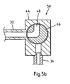
- the ball 46 in the in Fig. 5b rotated position shown.
- the supply line 32 communicates with the flow-through channel 48.
- extinguishing fluid can not flow into the discharge line 34, since there is no direct connection between supply line 32 and discharge line 34.
- the ball valve 44 seals the supply line 32 from the discharge line 34. By turning the ball 46 of the ball valve 44 by 90 ° can be determined whether the ball 46 is stuck.
- the ball 46 can be used without interference in the Fig. 5c rotated position shown. In this case, a direct connection between supply line 32 and discharge line 34 is ensured by the throughflow channel 48. extinguishing fluid can flow directly through the flow passage 48 into the drain 34 and a fire can be effectively combated.
Landscapes
- Engineering & Computer Science (AREA)
- General Engineering & Computer Science (AREA)
- Emergency Management (AREA)
- Health & Medical Sciences (AREA)
- Public Health (AREA)
- Business, Economics & Management (AREA)
- Mechanical Engineering (AREA)
- Fire-Extinguishing By Fire Departments, And Fire-Extinguishing Equipment And Control Thereof (AREA)
- Multiple-Way Valves (AREA)
- Taps Or Cocks (AREA)
- Fluid-Driven Valves (AREA)
- Safety Valves (AREA)
- Details Of Valves (AREA)
Description
- Die Erfindung betrifft ein Ventil für Rohrleitungen von Brandbekämpfungssystemen mit einer Zuleitung für mit Überdruck beaufschlagtes Löschfluid, mit einer Ableitung für das Löschfluid, mit zwischen der Zuleitung und der Ableitung angeordneten Sperrmitteln, und mit einem die Sperrmittel betreibenden Stellmittel zum Stellen der Sperrmittel in eine offene Position und eine geschlossene Position, wobei im Ruhezustand die Sperrmittel in der geschlossenen Position sind und wobei in einem Brandfall die Stellmittel die Sperrmittel aus der geschlossenen Position in die offene Position verstellen, derart, dass Löschfluid von der Zuleitung in die Ableitung fließt.
- Rohrleitungen von Brandbekämpfungssystemen sind regelmäßig bereits im Ruhezustand mit Löschfluid beaufschlagt. Diese so genannten Nass-Systeme zeichnen sich dadurch aus, dass Löschfluid in den Rohrleitungen permanent gelagert ist und im Brandfall das Löschfluid schnell an den Sprinklern bzw. Löschnebeldüsen anliegt.
- Um zu verhindern, dass Löschfluid im Ruhezustand aus dem Rohrleitungssystem austritt, ist vor Löschnebeldüsen bzw. an Abzweigungen in den Rohrleitungssystemen ein Absperrventil angeordnet. Dieses Ventil verhindert, dass Löschfluid unmittelbar an den Löschnebeldüsen anliegt. Im Brandfall werden die Ventile über ferngesteuerte Stellmotoren geöffnet, so dass Löschfluid aus den Löschnebeldüsen austritt.
- Zur Erkennung von Leckagen wird das Löschfluid im Ruhezustand permanent auf einem niedrigen Standby-Druck gehalten. Dieser Druck beträgt regelmäßig ca. 20 bar. Im Brandfall wird der Fluiddruck stark erhöht, so dass beispielsweise an den Löschnebeldüsen Feinstnebel vernebelt werden kann.
- Um sicher zu stellen, dass die Ventile im Brandfall auch funktionieren, müssen diese in regelmäßigen Abständen gewartet werden. Zur Wartung der Ventile werden diese aktiviert. Hierbei werden Kugelhähne beispielsweise um zumindest 90° gedreht. Dadurch werden Inkrustationen, eingebrachte Fremdkörper, aufgequollene Dichtungen, beschädigte Dichtungen, Korrosionen und weitere Ursachen für ein Festsitzen der Ventile entdeckt. Ein Festsitzen oder andere Fehlfunktionen der Ventile müssen frühzeitig festgestellt werden, um einen sicheren Betrieb im Brandfall gewährleisten zu können. Ein solches bekanntes Ventil wird in
US-B1- 6 196 262 beschrieben. - Bei den herkömmlichen Wartungsarbeiten werden die Ventile regelmäßig geöffnet. Hierzu bedient ein Service Techniker ein Absperrventil mit einem seitlichen Abgang. Ein Testventil wird manuell geöffnet und Löschfluid tritt über den seitlichen Abgang aus. Danach werden die Ventile wieder manuell in ihre ursprüngliche Position gebracht. Die Wartung führt dazu, dass regelmäßig Löschfluid neu in die Rohrleitung eingebracht und der Ruhedruck nachgeregelt werden muss. Das Austreten von Löschfluid bei Wartungsarbeiten kann ferner nachteilig sein, wenn in den abgesicherten Räumen feuchtigkeitsempfindliche Gegenstände aufbewahrt werden.
- Auf Grund dieser Nachteile lag der Erfindung die Aufgabe zugrunde, ein Ventil für Rohrleitungen von Brandbekämpfungssystemen zur Verfügung zu stellen, bei dem ein Festsitzen erkannt werden kann, ohne dass Löschfluid aus der Rohrleitung austritt.
- Insbesondere ist es möglich, über eine Fernwartung, bei der die Überwachung räumlich von den Ventilen getrennt angeordnet ist, die Sperrmittel zu warten. Vor allem in Tunneln von mehreren Kilometern Länger ist es sinnvoll, die Wartung der Ventile zentral zu steuern, so dass es nicht notwendig ist, dass ein Servicetechniker manuell alle Sperrmittel einzeln kontrolliert.
- Die zuvor aus dem Stand der Technik hergeleitete Aufgabe wird erfindungsgemäß dadurch gelöst, dass die Sperrmittel derart gebildet sind, dass in einem Wartungsbetrieb die Sperrmittel aus ihrer geschlossen Position mittels der Stellmittel verstellbar sind, derart, dass im Wartungsbetrieb kein Löschfluid von der Zuleitung in die Ableitung fließt.
- Es ist erkannt worden, dass ein Festsitzen der Sperrmittel dadurch festgestellt werden kann, dass die Sperrmittel mittels der Stellmittel während einer Wartung verstellt werden. Um das Austreten von Löschfluid während dieses Stellvorgangs im Wartungsbetrieb zu verhindern, sind die Sperrmittel derart vorgesehen, dass diese im Wartungsbetrieb keine Fluidkommunikation zwischen Zuleitung und Ableitung gestatten. Durch das Aufbringen eines Anlaufmoments beim Stellen der Sperrmittel im Wartungsbetrieb werden geringfügige Verkrustungen und Korrosionen aufgebrochen. Die Ventile sind danach wieder voll funktionstüchtig.
- Es ist besonders bevorzugt, wenn die Sperrmittel aus einem Kugelhahn gebildet sind, wobei der Kugelhahn zwischen der offen Position und der geschlossen Position eine Wartungsposition hat. Der Kugelhahn kann beispielsweise als 3/2 Wege-Kugelhahn gebildet sein. In diesem Fall kann eine Öffnung des Ventilkörpers verschlossen sein. Bei einem 3/2 Wege-Kugelhahn mit einer verschlossenen Öffnung kann die Kugel selbst mittels der Stellmittel um ca. 180° verdreht werden, ohne dass Löschfluid von der Zuleitung in eine Ableitung gelangt.
- Bei einem 3/2 Wege-Kugelhahn kann der Ventilkörper so gestaltet sein, dass die mit dem Ventileingang verbundene Ausgangsbohrung im Falle einer 90° Drehung der Kugel verschlossen ist. Die Kugel des Kugelhahns kann beliebige Bohrmuster aufweisen, die es gestatten, den Kugelhahn in eine Wartungsposition zwischen der offenen Position und der geschlossenen Position zu bringen, ohne dass Löschfluid von der Zuleitung in die Ableitung gelangt.
- Ein Festsitzen der Kugel eines Kugelhahns wird insbesondere dann leicht festgestellt, wenn der Kugelhahn im Wartungsbetrieb von den Stellmitteln um zumindest 50°, vorzugsweise zumindest 90° verstellbar ist. Ein Verstellen des Kugelhahns um zumindest 50° gestattet es, zuverlässig ein Festsitzen zu detektieren. Leichte Inkrustationen können aufgebrochen werden und die Funktionsfähigkeit des Kugelhahns kann gewährleistet bleiben.
- Die Bohrmuster in der Kugel des Kugelhahns können bevorzugt derart gestaltet sein, dass ein Winkel zwischen einer Einlassöffnung und einer Auslassöffnung des Kugelhahns zwischen 5° und 175°, vorzugsweise 90° ist. Die Anordnung von Öffnungen im Ventilkörper und Bohrungen in der Kugel des Kugelhahns können derart sein, dass sie eine Verstellung des Kugelhahns um zumindest 50° gestatten, ohne dass Löschfluid austritt.
- Es ist ebenfalls besonders bevorzugt, wenn die Sperrmittel eine Berstscheibe und einen Absperrhahn aufweisen. Die Berstscheibe ist derart gestaltet, dass sie erst bei einer Erhöhung des Ruhedrucks birst. Dies geschieht beispielsweise bei einem Brandfall. Der Absperrhahn verhindert, dass bei einer unbeabsichtigten Zerstörung der Berstscheibe Löschfluid aus den Löschnebeldüsen austritt. Die Berstscheibe bildet zusammen mit dem Absperrhahn eine doppelte Sicherung gegenüber Leckagen.
- Es ist ebenfalls besonders bevorzugt, wenn der Absperrhahn ein Kugelhahn oder ein Magnetventil ist.
- Besonders bevorzugt ist es, wenn die Berstscheibe zwischen Zuleitung und Absperrhahn angeordnet ist, derart, dass der Absperrhahn im Ruhezustand trocken ist. In diesem Falle ist die Berstscheibe so angeordnet, dass sie den Absperrhahn im Ruhezustand zuverlässig von der Zuleitung abdichtet. Der Absperrhahn lässt sich in diesem Falle für Wartungsarbeiten verstellen, ohne dass Löschfluid austritt. Das Löschfluid wird durch die Berstscheibe in der Zuleitung gehalten. Erst im Brandfall birst die Berstscheibe und die Stellmittel stellen den Absperrhahn in eine offene Position, so dass zuverlässig ein Brand bekämpft werden kann.
- Ebenfalls besonders bevorzugt ist, wenn die Berstscheibe zwischen Absperrhahn und Ableitung angeordnet ist, derart, dass der Absperrhahn im Ruhezustand mit Löschfluid beaufschlagt ist. In diesem Fall verhindert der Absperrhahn, dass die Berstscheibe versehentlich durch einen zu hohen Ruhedruck zerstört wird. Im Brandfall birst die Berstscheibe nach dem Öffnen des Absperrhahns, da ein erhöhter Fluiddruck herrscht. Im Wartungsfall kann der Absperrhahn ohne weiteres durch die Stellmittel geöffnet werden. Die Berstscheibe hält den Ruhedruck zerstörungsfrei aus. Löschfluid tritt nicht aus den Löschnebeldüsen aus, denn es wird durch die Berstscheibe zurückgehalten.
- Bevorzugt ist auch, wenn die Stellmittel hydraulisch, pneumatisch oder elektrisch betrieben sind. Solche Stellmittel können beispielsweise elektrisch betriebene Stellmotoren sein.
- Die Position der Stellmittel kann mittels Sensoren festgestellt werden. Diese Sensoren können beispielsweise Endlagenschalter und Wartungslagenschalter sein. Diese Schalter überwachen die Steuerung der Stellmittel. Die Sensoren können außerdem den Arbeitsbereich der Stellmittel steuern. Die Sensoren gestatten eine Fernwartung der Sperrmittel mittels Fernsteuerung der Motoren und Überwachung der Motorfunktion bzw. der Position der Stellmittel.
- Weitere Vorteile ergeben sich aus den nachgeordneten Ansprüchen.
- Nachfolgend wird die Erfindung anhand einer Ausführungsbeispiele zeigenden Zeichnung näher erläutert.
- In der Zeichnung zeigen:
- Fig. 1
- ein Brandbekämpfungssystem zum Löschen eines Feuers in schematischer Darstellung;
- Fig. 2
- eine Variante eines Systems gemäß
Fig. 1 ; - Fig. 3
- ein Ventil mit einer Berstscheibe gemäß eines ersten Ausführungsbeispiels;
- Fig. 4
- ein Ventil mit einer Berstscheibe gemäß eines zweiten Ausführungsbeispiels;
- Fig. 5a
- ein Ventil mit einem Kugelhahn in einer geschlossenen Position;
- Fig. 5b
- ein Ventil mit einem Kugelhahn in einer Wartungsposition;
- Fig. 5c
- ein Ventil mit einem Kugelhahn in einer offenen Position.
- Die Vorrichtung 1 zum Löschen eines Brandes weist eine Löschfluidversorgung 2 auf, welche im einzelnen nicht gezeigte Fluidbehälter und eine Hochdruckpumpe umfasst. Alternativ kann die Löschfluidversorgung 2 auch mit einem oder mehreren Druckspeichern ausgestattet sein, in welchen Löschfluid unter Druck gespeichert ist. Weiter kann das Löschfluid unter Umgebungsdruck bevorratet und nur im Aktivierungsfall aus einem oder mehreren Druckspeichern mit Druck beaufschlagt werden. Die Löschfluidversorgung 2 wird von einer Steuereinrichtung 3 gesteuert, welche das Brandmeldesignal eines Brandwächters 4 empfängt.
- Beim Ausführungsbeispiel gemäß
Fig. 1 sind über eine Hauptversorgungsleitung 6 und jeweils eigene, von der Hauptversorgungsleitung 6 abzweigende Versorgungsleitungen 7,8,9 Löschdüsen 10,11,12 an die Löschfluidversorgung 2 angeschlossen. - Beim Ausführungsbeispiel gemäß
Fig. 2 ist eine erste Gruppe 13 von drei Löschdüsen 14 über ein Verzweigungsstück 15 an eine von einer Hauptversorgungsleitung 16 abgehende Versorgungsleitung 17 angeschlossen. Des Weiteren ist eine einzelne Löschdüse 18 unmittelbar an eine Versorgungsleitung 19 angeschlossen, die ebenfalls von der Hauptversorgungsleitung 16 abgeht. Bei einer dritten Gruppe 20 von drei Löschdüsen 21 sind die Löschdüsen 21 schließlich über Zwischenleitungen 22 und ein Verzweigungsstück 23 an eine dritte, von der Hauptversorgungsleitung 16 abgehende Versorgungsleitung 24 angeschlossen. - Die Löschdüsen 10,11,12,14,18,21 können offene Düseneinsätze aufweisen, welche über in der jeweiligen Löschdüse ausgebildete Kanäle mit einer Einströmbohrung der Löschdüse verbunden sind. Die Düseneinsätze erzeugen bei Beaufschlagung mit einem Löschfluid unter hohem Druck von bis zu 300 bar einen sich fein verteilenden Löschnebel.
-
Fig. 3 zeigt ein Ventil 50 gemäß eines ersten vorteilhaften Ausführungsbeispiels. Über die Versorgungsleitung 7 liegt Löschfluid bei einem Ruhedruck von ca. 20 bar an der Zuleitung 32 des Ventils 50 an. Das Ventil 50 weist eine Berstscheibe 30, eine Zuleitung 32, eine Ableitung 34, einen Absperrhahn 36, Stellmittel 38 und Sensoren 40 auf. - Das Löschfluid wird durch die Berstscheibe 30 in der Versorgungsleitung 7 gehalten. Sie dichtet das Ventil 50, insbesondere den Absperrhahn 36 gegenüber dem Löschfluid ab. Im Ruhezustand ist der Absperrhahn 36 trocken. Zur Wartung kann mittels der Stellmittel 38 die Position des Absperrhahns 36 verändert werden. Beispielsweise kann der Absperrhahn 36 durch ein Magnetventil gebildet sein, welches eine offene und eine geschlossene Position hat. Die Stellmittel 38 können ferngesteuert werden.
- Mittels der Stellmittel 38 kann zwischen der offenen Position und der geschlossenen Position hin- und hergeschaltet werden. Die Position der Stellmittel 38 wird durch die Sensoren 40 detektiert. Mittels eines Hilfsantriebs (nicht gezeigt) werden die Stellmittel 38 im Wartungsfall von der gezeigten Position über dem Sensor 40a in eine Position über dem Sensor 40b verstellt. Der Sensor 40b detektiert die Verstellung der Stellmittel 38 und meldet dies an eine Steuereinrichtung, so dass die Verstellung gestoppt wird. Danach werden die Stellmittel 38 über den Hilfsantrieb wieder zurück in die gezeigte Position gestellt. Das Erreichen dieser Position wird über den Sensor 40a detektiert. Durch das Verstellen im Wartungsintervall werden Inkrustationen und Korrosionen in den Sperrmitteln 36 festgestellt.
- Im Brandfall wird der Fluiddruck erhöht, was dazu führt, dass die Berstscheibe 30 birst. Zusätzlich wird mittels der Stellmittel 38 der Absperrhahn 36 in eine offene Position gestellt, so dass Löschfluid von der Zuleitung 32 in die Ableitung 34 fließen kann und ein Feuer bekämpft werden kann.
-
Fig. 4 zeigt eine weitere Ausgestaltung eines erfindungsgemäßen Ventils 50. Hierbei ist die Berstscheibe 30 hinter dem Absperrhahn 36 angeordnet. Der Absperrhahn 36 ist im Ruhezustand mit Löschfluid beaufschlagt. Das Verstellen der Stellmittel 38 von der geschlossenen Position in die offene Position bewirkt, dass Löschfluid in der Ableitung 34 an der Berstscheibe 30 anliegt. Die Berstscheibe 30 dichtet die Ableitung 34 von der weiteren Rohrleitung ab, so dass kein Löschfluid austreten kann. - Im Brandfall werden die Stellmittel 38 verstellt, so dass der Absperrhahn 36 in einer offenen Position ist. Das Löschfluid liegt mit erhöhtem Druck an der Berstscheibe 30 an, so dass diese birst und eine Brandbekämpfung erfolgen kann.
-
Fig. 5a zeigt einen Kugelhahn 44 in schematischer Darstellung. Der Kugelhahn 44 weist eine Kugel 46 mit einem Durchströmkanal 48 auf. Die Kugel 46 wird über Stellmittel (nicht gezeigt) verstellt. Die Position der Kugel 46 wird mittels Sensoren (nicht gezeigt) detektiert. In der inFig. 5a gezeigten Position ist die Kugel 46 in einer geschlossenen Position. Der Durchströmkanal 48 der Kugel 46 ist so gestaltet, dass er weder mit der Zuleitung 32 noch mit der Ableitung 34 kommuniziert. - Im Wartungsfall wird die Kugel 46 in die in
Fig. 5b gezeigte Position verdreht. Hierbei kommuniziert die Zuleitung 32 mit dem Durchströmkanal 48. Löschfluid kann jedoch nicht in die Ableitung 34 fließen, da keine unmittelbare Verbindung zwischen Zuleitung 32 und Ableitung 34 besteht. Der Kugelhahn 44 dichtet die Zuleitung 32 von der Ableitung 34 ab. Durch das Verdrehen der Kugel 46 des Kugelhahns 44 um 90° kann festgestellt werden, ob die Kugel 46 festsitzt. - Durch das regelmäßige Verstellen der Kugel 46 von der in
Fig. 5a gezeigten Position in die inFig. 5b gezeigte Position kann ein Festsitzen der Kugel 46 festgestellt werden. Im Falle eines Festsitzens kann das Ventil 50 ausgetauscht werden. - Dadurch, dass die Funktion des Kugelhahns 44 regelmäßig überwacht wird, kann im Brandfall die Kugel 46 ohne Beeinträchtigung in die in
Fig. 5c gezeigte Position verdreht werden. In diesem Falle wird durch den Durchströmkanal 48 eine direkte Verbindung zwischen Zuleitung 32 und Ableitung 34 gewährleistet. Löschfluid kann direkt durch den Durchströmkanal 48 in die Ableitung 34 fließen und ein Brand kann wirksam bekämpft werden.
Claims (13)
- Ventil für Rohrleitungen von Brandbekämpfungssystemen (1),- mit einer Zuleitung (32) für mit Überdruck beaufschlagtes Löschfluid,- mit einer Ableitung (34) für das Löschfluid,- mit zwischen der Zuleitung (32) und der Ableitung (34) angeordneten Sperrmitteln (36, 46), und- mit einem die Sperrmittel (36, 46) betreibenden Stellmittel (38) zum Stellen der Sperrmittel (36, 46) in eine offene Position und eine geschlossene Position, wobei im Ruhezustand die Sperrmittel (36, 46) in der geschlossenen Position sind und wobei in einem Brandfall die Stellmittel (38) die Sperrmittel (36, 46) aus der geschlossenen Position in die offene Position verstellen, derart, dass Löschfluid von der Zuleitung (32) in die Ableitung (34) fließt,
dadurch gekennzeichnet,- dass die Sperrmittel (36, 46) derart gebildet sind, dass in einem Wartungsbetrieb die Sperrmittel (36, 46) mittels der Stellmittel (38) aus ihrer geschlossenen Position verstellbar sind, derart, dass im Wartungsbetrieb kein Löschfluid von der Zuleitung (32) in die Ableitung (34) fließt. - Ventil nach Anspruch 1, dadurch gekennzeichnet, dass die Sperrmittel (36, 46) aus einem Kugelhahn (46) gebildet sind, wobei der Kugelhahn (46) zwischen der offenen Position und der geschlossenen Position eine Wartungsposition hat.
- Ventil nach Anspruch 2, dadurch gekennzeichnet, dass der Kugelhahn (46) im Wartungsbetrieb von den Stellmitteln (38) aus der geschlossenen Position in die Wartungsposition verstellbar ist.
- Ventil nach Anspruch 2 oder 3, dadurch gekennzeichnet, dass der Kugelhahn (46) im Wartungsbetrieb von den Stellmitteln (38) um zumindest 50°, vorzugsweise zumindest 90° verstellbar ist.
- Ventil nach einem der Ansprüche 2 bis 4, dadurch gekennzeichnet, dass ein Winkel zwischen einer Einlassöffnung und einer Auslassöffnung des Kugelhahns (46) zwischen 5° und 175°, vorzugsweise 90° ist.
- Ventil nach einem der Ansprüche 1 bis 5, dadurch gekennzeichnet, dass die Sperrmittel (36, 46) eine Berstscheibe (30) und einen Absperrhahn (36) aufweisen.
- Ventil nach einem der Ansprüche 1 bis 6, dadurch gekennzeichnet, dass der Absperrhahn (36) ein Kugelhahn (46) oder ein Magnetventil (36) ist.
- Ventil nach einem der Ansprüche 1 bis 7, dadurch gekennzeichnet, dass die Berstscheibe (30) derart zwischen Zuleitung (32) und Absperrhahn (36) angeordnet ist, dass der Absperrhahn (36) im Ruhezustand trocken ist.
- Ventil nach einem der Ansprüche 1 bis 8, dadurch gekennzeichnet, dass im Brandfall der Fluiddruck derart erhöht wird, dass die Berstscheibe (30) birst.
- Ventil nach einem der Ansprüche 1 bis 9, dadurch gekennzeichnet, dass die Berstscheibe (30) derart zwischen Absperrhahn (36) und Ableitung (34) angeordnet ist, dass der Absperrhahn (36) im Ruhezustand mit Löschfluid beaufschlagt ist.
- Ventil nach einem der Ansprüche 1 bis 10, dadurch gekennzeichnet, dass die Stellmittel (38) hydraulisch, pneumatisch und/oder elektrisch betrieben sind.
- Ventil nach einem der Ansprüche 1 bis 11, dadurch gekennzeichnet, dass die Stellmittel (38) einen Stellmotor aufweisen.
- Ventil nach einem der Ansprüche 1 bis 12, dadurch gekennzeichnet, dass die Position der Stellmittel (38) ermittelnde Sensoren (40) vorgesehen sind.
Applications Claiming Priority (2)
| Application Number | Priority Date | Filing Date | Title |
|---|---|---|---|
| DE200510014275 DE102005014275B4 (de) | 2005-03-24 | 2005-03-24 | Servicefreundliches Ventil für Brandbekämpfungssysteme |
| PCT/EP2006/060877 WO2006100221A1 (de) | 2005-03-24 | 2006-03-20 | Servicefreundliches ventil für brandbekämpfungssysteme |
Publications (2)
| Publication Number | Publication Date |
|---|---|
| EP1861176A1 EP1861176A1 (de) | 2007-12-05 |
| EP1861176B1 true EP1861176B1 (de) | 2010-05-26 |
Family
ID=36643396
Family Applications (1)
| Application Number | Title | Priority Date | Filing Date |
|---|---|---|---|
| EP20060725168 Active EP1861176B1 (de) | 2005-03-24 | 2006-03-20 | Servicefreundliches ventil für brandbekämpfungssysteme |
Country Status (12)
| Country | Link |
|---|---|
| US (1) | US20090001309A1 (de) |
| EP (1) | EP1861176B1 (de) |
| JP (1) | JP4814306B2 (de) |
| CN (1) | CN101146577B (de) |
| AT (1) | ATE468893T1 (de) |
| BR (1) | BRPI0609311A2 (de) |
| DE (2) | DE102005014275B4 (de) |
| DK (1) | DK1861176T3 (de) |
| NO (1) | NO20074842L (de) |
| RU (1) | RU2388510C2 (de) |
| WO (1) | WO2006100221A1 (de) |
| ZA (1) | ZA200707807B (de) |
Families Citing this family (15)
| Publication number | Priority date | Publication date | Assignee | Title |
|---|---|---|---|---|
| DE102007062834A1 (de) * | 2007-12-21 | 2009-08-06 | Fogtec Brandschutz Gmbh & Co. Kg | Schutzeinrichtung für Brandbekämpfungsanlagen |
| DE102009053551A1 (de) | 2009-11-18 | 2011-05-19 | Fogtec Brandschutz Gmbh & Co. Kg | Brandbekämpfungssystem für ein Schienenfahrzeug |
| US9155927B2 (en) * | 2010-05-11 | 2015-10-13 | Jeffrey T. Newton | Self-contained self-actuated modular fire suppression unit |
| JP5547014B2 (ja) * | 2010-09-27 | 2014-07-09 | 株式会社コーアツ | ガス系消火剤貯蔵容器用容器弁 |
| DE102014226639A1 (de) * | 2014-12-19 | 2016-06-23 | Minimax Gmbh & Co. Kg | Feuerlöschanlagenventile und Feuerlöschanlagen mit selbigen |
| US10596401B2 (en) | 2016-08-11 | 2020-03-24 | Victaulic Company | Modular valve assembly |
| JP6893776B2 (ja) * | 2016-12-05 | 2021-06-23 | ホーチキ株式会社 | 消火システム |
| US20180193681A1 (en) | 2017-01-06 | 2018-07-12 | Globe Fire Sprinkler Corporation | Control valve assembly with test, drain and adjustable pressure relief valve |
| WO2019190609A1 (en) | 2018-03-29 | 2019-10-03 | Globe Fire Sprinkler Corporation | Combination control and check valve assembly for a wet piping system |
| TWI685362B (zh) * | 2019-03-22 | 2020-02-21 | 鴻威消防科技股份有限公司 | 消防水池抽換式底閥及具該抽換式底閥的汲水系統 |
| WO2021055730A1 (en) | 2019-09-20 | 2021-03-25 | Victaulic Company | Ball valve assembly |
| RU2754440C1 (ru) * | 2020-10-29 | 2021-09-02 | Общество с ограниченной ответственностью НПО «Современные пожарные технологии» | Быстродействующая автоматическая пожаротушащая система |
| RU2754439C1 (ru) * | 2020-10-29 | 2021-09-02 | Общество с ограниченной ответственностью НПО «Современные пожарные технологии» | Запорно-пусковое устройство быстродействующей автоматической пожаротушащей системы |
| CN112915443B (zh) * | 2021-02-26 | 2022-06-21 | 西拓能源集团有限公司 | 一种智能防火装置 |
| CN113294545B (zh) * | 2021-05-20 | 2023-07-28 | 中车青岛四方机车车辆股份有限公司 | 管接塞门、管接塞门的组装方法及轨道车辆 |
Family Cites Families (20)
| Publication number | Priority date | Publication date | Assignee | Title |
|---|---|---|---|---|
| DE2622680A1 (de) * | 1976-05-21 | 1978-01-19 | Bauknecht Feuerschutz | Sprinkleranlage |
| US5103862A (en) * | 1986-06-16 | 1992-04-14 | Agf Manufacturing, Inc. | Valve and arrangement for fire suppression water sprinkle system |
| US4941319A (en) * | 1987-09-30 | 1990-07-17 | Honda Giken Kogyo Kabushiki Kaisha | Engine control device |
| US4809949A (en) * | 1988-01-26 | 1989-03-07 | Dresser Industries, Inc. | Plug valve |
| US5052655A (en) * | 1990-07-18 | 1991-10-01 | Watts Regulator Company | Ball valve lock plate |
| DE4026785A1 (de) * | 1990-08-24 | 1992-02-27 | Bosch Gmbh Robert | Stellvorrichtung |
| DE4115101A1 (de) * | 1991-05-08 | 1992-11-12 | Total Feuerschutz Gmbh | Dosierventil fuer schaummittel |
| US5486811A (en) * | 1994-02-09 | 1996-01-23 | The United States Of America As Represented By The Secretary Of The Navy | Fire detection and extinguishment system |
| US5562116A (en) * | 1995-02-06 | 1996-10-08 | Henwood; Gerard S. | Angle entry rotary valve |
| DE19514939C2 (de) * | 1995-04-22 | 1997-09-18 | Kamat Pumpen Gmbh & Co Kg | Löschdüsenkopf |
| JPH09280390A (ja) * | 1996-04-12 | 1997-10-28 | Asahi Organic Chem Ind Co Ltd | 三方ボールバルブ |
| US5671911A (en) * | 1996-08-07 | 1997-09-30 | Amcast Industrial Corporation | By-pass ball valve |
| US5901760A (en) * | 1997-12-12 | 1999-05-11 | Illinois Tool Works Inc. | Automotive fuel filler pipe ball valve assembly |
| ITCO990004A1 (it) * | 1999-01-11 | 2000-07-11 | Giacomini Spa | Valvola perfezionata per la prova e lo scarico di impiantiantincendio a nebulizzazione. |
| WO2002078788A2 (en) * | 2001-03-29 | 2002-10-10 | Kidde Ip Holdings Limited | Fire and explosion suppression |
| US6491109B2 (en) * | 2001-05-11 | 2002-12-10 | Joel P. Christenson | Kinetic antifreeze device |
| FI113155B (fi) * | 2002-01-17 | 2004-03-15 | Marioff Corp Oy | Venttiilielin |
| US6896067B2 (en) * | 2002-09-23 | 2005-05-24 | James Bowyer | Method and apparatus for distributing fire suppressant |
| JP2004257399A (ja) * | 2003-02-24 | 2004-09-16 | Ishikawajima Harima Heavy Ind Co Ltd | ボールバルブ |
| US6860333B2 (en) * | 2003-03-28 | 2005-03-01 | The Boeing Company | Thermally activated fire suppression system |
-
2005
- 2005-03-24 DE DE200510014275 patent/DE102005014275B4/de not_active Expired - Fee Related
-
2006
- 2006-03-20 RU RU2007139331A patent/RU2388510C2/ru not_active IP Right Cessation
- 2006-03-20 AT AT06725168T patent/ATE468893T1/de active
- 2006-03-20 WO PCT/EP2006/060877 patent/WO2006100221A1/de active Application Filing
- 2006-03-20 DE DE200650007033 patent/DE502006007033D1/de active Active
- 2006-03-20 US US11/909,027 patent/US20090001309A1/en not_active Abandoned
- 2006-03-20 CN CN2006800091108A patent/CN101146577B/zh active Active
- 2006-03-20 EP EP20060725168 patent/EP1861176B1/de active Active
- 2006-03-20 BR BRPI0609311-6A patent/BRPI0609311A2/pt not_active Application Discontinuation
- 2006-03-20 DK DK06725168T patent/DK1861176T3/da active
- 2006-03-20 JP JP2008502391A patent/JP4814306B2/ja not_active Expired - Fee Related
-
2007
- 2007-09-12 ZA ZA200707807A patent/ZA200707807B/en unknown
- 2007-09-24 NO NO20074842A patent/NO20074842L/no not_active Application Discontinuation
Also Published As
| Publication number | Publication date |
|---|---|
| JP2008534038A (ja) | 2008-08-28 |
| NO20074842L (no) | 2007-12-21 |
| BRPI0609311A2 (pt) | 2010-03-09 |
| DK1861176T3 (da) | 2010-09-13 |
| CN101146577A (zh) | 2008-03-19 |
| DE502006007033D1 (de) | 2010-07-08 |
| DE102005014275A1 (de) | 2006-10-05 |
| ZA200707807B (en) | 2008-07-30 |
| JP4814306B2 (ja) | 2011-11-16 |
| RU2388510C2 (ru) | 2010-05-10 |
| EP1861176A1 (de) | 2007-12-05 |
| CN101146577B (zh) | 2011-03-23 |
| ATE468893T1 (de) | 2010-06-15 |
| RU2007139331A (ru) | 2009-04-27 |
| US20090001309A1 (en) | 2009-01-01 |
| DE102005014275B4 (de) | 2008-06-19 |
| WO2006100221A1 (de) | 2006-09-28 |
Similar Documents
| Publication | Publication Date | Title |
|---|---|---|
| EP1861176B1 (de) | Servicefreundliches ventil für brandbekämpfungssysteme | |
| EP3713649B1 (de) | Wasserlöschanlage und zugehöriges verfahren zum kontrollieren der wasserlöschanlage | |
| EP3554652B1 (de) | Feuerlöschanlagenventil, insbesondere nassalarm-, trockenalarm- oder sprühwasserventil, und feuerlöschanlage mit selbigem | |
| EP1224014B1 (de) | Vorrichtung zum löschen eines feuers | |
| EP3842101A1 (de) | Wasserlöschanlage und verfahren zum steuern eines pumpentestlaufs in einer wasserlöschanlage | |
| WO2011141356A1 (de) | Ventil | |
| DE102007049588B4 (de) | Elektrisch gesteuerter Schnellentlüfter für ein Trockenrohrnetz mit Sprinklern | |
| DE2255369C3 (de) | Vorrichtung zum Betreiben einer Sprinkleranlage | |
| DE102010033178B3 (de) | Vorgesteuertes Trockenalarmventil für ein Sprinklernetz | |
| WO2019025495A1 (de) | Feuerlöschanlagenventil, insbesondere nassalarm-, trockenalarm-, oder sprühwasserventil sowie steuermodul für selbiges und feuerlöschanlage mit selbigem | |
| DE3230086A1 (de) | Trockenalarmventil/spruehflutventil fuer feuerloeschanlagen | |
| EP1220705B1 (de) | Vorrichtung zum löschen von feuer | |
| DE19601777A1 (de) | Stationäre Feuerlöschanlage | |
| EP3727610A1 (de) | Pneumatisches steuergerät für mehrbereichs-feuerlöschanlagen, sowie mehrbereichs-feuerlöschanlage mit selbigem | |
| DE4320442A1 (de) | Vorrichtung für eine stationäre Feuerlöschanlage | |
| DE202005021484U1 (de) | Servicefreundliches Ventil für Brandbekämpfungssysteme | |
| EP1110583B1 (de) | Feuerlöschanlage | |
| WO2019063373A1 (de) | Trockenalarmventilstation, und feuerlöschanlage mit selbiger | |
| DE102016202441A1 (de) | Alarmventilstation einer Feuerlöschanlage und Feuerlöschanlage | |
| WO2022106671A1 (de) | Mehrbereichs-feuerlöschanlage und bereichs-blockiervorrichtung | |
| DE102008038275A1 (de) | Branddetektionssystem | |
| DE102004024303B3 (de) | Feuerlöschanlage | |
| DE2911814C2 (de) | ||
| WO2009083282A1 (de) | Schutzeinrichtung für brandbekämpfungsanlagen | |
| DE10156284A1 (de) | Absperrarmatur für einen Strömungswächter |
Legal Events
| Date | Code | Title | Description |
|---|---|---|---|
| PUAI | Public reference made under article 153(3) epc to a published international application that has entered the european phase |
Free format text: ORIGINAL CODE: 0009012 |
|
| 17P | Request for examination filed |
Effective date: 20070906 |
|
| AK | Designated contracting states |
Kind code of ref document: A1 Designated state(s): AT BE BG CH CY CZ DE DK EE ES FI FR GB GR HU IE IS IT LI LT LU LV MC NL PL PT RO SE SI SK TR |
|
| AX | Request for extension of the european patent |
Extension state: HR |
|
| RAX | Requested extension states of the european patent have changed |
Extension state: HR Payment date: 20070906 |
|
| GRAP | Despatch of communication of intention to grant a patent |
Free format text: ORIGINAL CODE: EPIDOSNIGR1 |
|
| GRAS | Grant fee paid |
Free format text: ORIGINAL CODE: EPIDOSNIGR3 |
|
| GRAA | (expected) grant |
Free format text: ORIGINAL CODE: 0009210 |
|
| AK | Designated contracting states |
Kind code of ref document: B1 Designated state(s): AT BE BG CH CY CZ DE DK EE ES FI FR GB GR HU IE IS IT LI LT LU LV MC NL PL PT RO SE SI SK TR |
|
| AX | Request for extension of the european patent |
Extension state: HR |
|
| REG | Reference to a national code |
Ref country code: GB Ref legal event code: FG4D Free format text: NOT ENGLISH |
|
| REG | Reference to a national code |
Ref country code: CH Ref legal event code: EP |
|
| REG | Reference to a national code |
Ref country code: IE Ref legal event code: FG4D Free format text: LANGUAGE OF EP DOCUMENT: GERMAN |
|
| REG | Reference to a national code |
Ref country code: CH Ref legal event code: NV Representative=s name: TROESCH SCHEIDEGGER WERNER AG |
|
| REF | Corresponds to: |
Ref document number: 502006007033 Country of ref document: DE Date of ref document: 20100708 Kind code of ref document: P |
|
| REG | Reference to a national code |
Ref country code: NL Ref legal event code: T3 |
|
| REG | Reference to a national code |
Ref country code: DK Ref legal event code: T3 |
|
| LTIE | Lt: invalidation of european patent or patent extension |
Effective date: 20100526 |
|
| PG25 | Lapsed in a contracting state [announced via postgrant information from national office to epo] |
Ref country code: SE Free format text: LAPSE BECAUSE OF FAILURE TO SUBMIT A TRANSLATION OF THE DESCRIPTION OR TO PAY THE FEE WITHIN THE PRESCRIBED TIME-LIMIT Effective date: 20100526 Ref country code: LT Free format text: LAPSE BECAUSE OF FAILURE TO SUBMIT A TRANSLATION OF THE DESCRIPTION OR TO PAY THE FEE WITHIN THE PRESCRIBED TIME-LIMIT Effective date: 20100526 |
|
| PG25 | Lapsed in a contracting state [announced via postgrant information from national office to epo] |
Ref country code: LV Free format text: LAPSE BECAUSE OF FAILURE TO SUBMIT A TRANSLATION OF THE DESCRIPTION OR TO PAY THE FEE WITHIN THE PRESCRIBED TIME-LIMIT Effective date: 20100526 Ref country code: SI Free format text: LAPSE BECAUSE OF FAILURE TO SUBMIT A TRANSLATION OF THE DESCRIPTION OR TO PAY THE FEE WITHIN THE PRESCRIBED TIME-LIMIT Effective date: 20100526 Ref country code: IS Free format text: LAPSE BECAUSE OF FAILURE TO SUBMIT A TRANSLATION OF THE DESCRIPTION OR TO PAY THE FEE WITHIN THE PRESCRIBED TIME-LIMIT Effective date: 20100926 |
|
| PG25 | Lapsed in a contracting state [announced via postgrant information from national office to epo] |
Ref country code: PL Free format text: LAPSE BECAUSE OF FAILURE TO SUBMIT A TRANSLATION OF THE DESCRIPTION OR TO PAY THE FEE WITHIN THE PRESCRIBED TIME-LIMIT Effective date: 20100526 Ref country code: CY Free format text: LAPSE BECAUSE OF FAILURE TO SUBMIT A TRANSLATION OF THE DESCRIPTION OR TO PAY THE FEE WITHIN THE PRESCRIBED TIME-LIMIT Effective date: 20100526 Ref country code: GR Free format text: LAPSE BECAUSE OF FAILURE TO SUBMIT A TRANSLATION OF THE DESCRIPTION OR TO PAY THE FEE WITHIN THE PRESCRIBED TIME-LIMIT Effective date: 20100827 |
|
| REG | Reference to a national code |
Ref country code: IE Ref legal event code: FD4D |
|
| PG25 | Lapsed in a contracting state [announced via postgrant information from national office to epo] |
Ref country code: IE Free format text: LAPSE BECAUSE OF FAILURE TO SUBMIT A TRANSLATION OF THE DESCRIPTION OR TO PAY THE FEE WITHIN THE PRESCRIBED TIME-LIMIT Effective date: 20100526 Ref country code: EE Free format text: LAPSE BECAUSE OF FAILURE TO SUBMIT A TRANSLATION OF THE DESCRIPTION OR TO PAY THE FEE WITHIN THE PRESCRIBED TIME-LIMIT Effective date: 20100526 Ref country code: PT Free format text: LAPSE BECAUSE OF FAILURE TO SUBMIT A TRANSLATION OF THE DESCRIPTION OR TO PAY THE FEE WITHIN THE PRESCRIBED TIME-LIMIT Effective date: 20100927 |
|
| PG25 | Lapsed in a contracting state [announced via postgrant information from national office to epo] |
Ref country code: CZ Free format text: LAPSE BECAUSE OF FAILURE TO SUBMIT A TRANSLATION OF THE DESCRIPTION OR TO PAY THE FEE WITHIN THE PRESCRIBED TIME-LIMIT Effective date: 20100526 Ref country code: RO Free format text: LAPSE BECAUSE OF FAILURE TO SUBMIT A TRANSLATION OF THE DESCRIPTION OR TO PAY THE FEE WITHIN THE PRESCRIBED TIME-LIMIT Effective date: 20100526 Ref country code: SK Free format text: LAPSE BECAUSE OF FAILURE TO SUBMIT A TRANSLATION OF THE DESCRIPTION OR TO PAY THE FEE WITHIN THE PRESCRIBED TIME-LIMIT Effective date: 20100526 |
|
| PLBE | No opposition filed within time limit |
Free format text: ORIGINAL CODE: 0009261 |
|
| STAA | Information on the status of an ep patent application or granted ep patent |
Free format text: STATUS: NO OPPOSITION FILED WITHIN TIME LIMIT |
|
| 26N | No opposition filed |
Effective date: 20110301 |
|
| REG | Reference to a national code |
Ref country code: DE Ref legal event code: R097 Ref document number: 502006007033 Country of ref document: DE Effective date: 20110228 |
|
| BERE | Be: lapsed |
Owner name: FOGTEC BRANDSCHUTZ G.M.B.H. & CO. KG Effective date: 20110331 |
|
| PG25 | Lapsed in a contracting state [announced via postgrant information from national office to epo] |
Ref country code: MC Free format text: LAPSE BECAUSE OF NON-PAYMENT OF DUE FEES Effective date: 20110331 |
|
| GBPC | Gb: european patent ceased through non-payment of renewal fee |
Effective date: 20110320 |
|
| PG25 | Lapsed in a contracting state [announced via postgrant information from national office to epo] |
Ref country code: BE Free format text: LAPSE BECAUSE OF NON-PAYMENT OF DUE FEES Effective date: 20110331 |
|
| PG25 | Lapsed in a contracting state [announced via postgrant information from national office to epo] |
Ref country code: GB Free format text: LAPSE BECAUSE OF NON-PAYMENT OF DUE FEES Effective date: 20110320 |
|
| PGFP | Annual fee paid to national office [announced via postgrant information from national office to epo] |
Ref country code: FI Payment date: 20120322 Year of fee payment: 7 |
|
| PG25 | Lapsed in a contracting state [announced via postgrant information from national office to epo] |
Ref country code: LU Free format text: LAPSE BECAUSE OF NON-PAYMENT OF DUE FEES Effective date: 20110320 |
|
| PG25 | Lapsed in a contracting state [announced via postgrant information from national office to epo] |
Ref country code: BG Free format text: LAPSE BECAUSE OF FAILURE TO SUBMIT A TRANSLATION OF THE DESCRIPTION OR TO PAY THE FEE WITHIN THE PRESCRIBED TIME-LIMIT Effective date: 20100826 Ref country code: TR Free format text: LAPSE BECAUSE OF FAILURE TO SUBMIT A TRANSLATION OF THE DESCRIPTION OR TO PAY THE FEE WITHIN THE PRESCRIBED TIME-LIMIT Effective date: 20100526 |
|
| PG25 | Lapsed in a contracting state [announced via postgrant information from national office to epo] |
Ref country code: HU Free format text: LAPSE BECAUSE OF FAILURE TO SUBMIT A TRANSLATION OF THE DESCRIPTION OR TO PAY THE FEE WITHIN THE PRESCRIBED TIME-LIMIT Effective date: 20100526 Ref country code: ES Free format text: LAPSE BECAUSE OF FAILURE TO SUBMIT A TRANSLATION OF THE DESCRIPTION OR TO PAY THE FEE WITHIN THE PRESCRIBED TIME-LIMIT Effective date: 20100906 Ref country code: FI Free format text: LAPSE BECAUSE OF NON-PAYMENT OF DUE FEES Effective date: 20130320 |
|
| REG | Reference to a national code |
Ref country code: FR Ref legal event code: PLFP Year of fee payment: 11 |
|
| PG25 | Lapsed in a contracting state [announced via postgrant information from national office to epo] |
Ref country code: IT Free format text: LAPSE BECAUSE OF NON-PAYMENT OF DUE FEES Effective date: 20160320 |
|
| REG | Reference to a national code |
Ref country code: FR Ref legal event code: PLFP Year of fee payment: 12 |
|
| PG25 | Lapsed in a contracting state [announced via postgrant information from national office to epo] |
Ref country code: IT Free format text: LAPSE BECAUSE OF NON-PAYMENT OF DUE FEES Effective date: 20160320 |
|
| PGRI | Patent reinstated in contracting state [announced from national office to epo] |
Ref country code: IT Effective date: 20170710 |
|
| REG | Reference to a national code |
Ref country code: FR Ref legal event code: PLFP Year of fee payment: 13 |
|
| PGFP | Annual fee paid to national office [announced via postgrant information from national office to epo] |
Ref country code: CH Payment date: 20220321 Year of fee payment: 17 |
|
| PGFP | Annual fee paid to national office [announced via postgrant information from national office to epo] |
Ref country code: NL Payment date: 20220323 Year of fee payment: 17 |
|
| PGFP | Annual fee paid to national office [announced via postgrant information from national office to epo] |
Ref country code: IT Payment date: 20220324 Year of fee payment: 17 |
|
| PGFP | Annual fee paid to national office [announced via postgrant information from national office to epo] |
Ref country code: FR Payment date: 20230323 Year of fee payment: 18 Ref country code: DK Payment date: 20230329 Year of fee payment: 18 |
|
| P01 | Opt-out of the competence of the unified patent court (upc) registered |
Effective date: 20230513 |
|
| REG | Reference to a national code |
Ref country code: CH Ref legal event code: PL |
|
| REG | Reference to a national code |
Ref country code: NL Ref legal event code: MM Effective date: 20230401 |
|
| PG25 | Lapsed in a contracting state [announced via postgrant information from national office to epo] |
Ref country code: NL Free format text: LAPSE BECAUSE OF NON-PAYMENT OF DUE FEES Effective date: 20230401 |
|
| PG25 | Lapsed in a contracting state [announced via postgrant information from national office to epo] |
Ref country code: LI Free format text: LAPSE BECAUSE OF NON-PAYMENT OF DUE FEES Effective date: 20230331 Ref country code: CH Free format text: LAPSE BECAUSE OF NON-PAYMENT OF DUE FEES Effective date: 20230331 |
|
| PGFP | Annual fee paid to national office [announced via postgrant information from national office to epo] |
Ref country code: AT Payment date: 20240322 Year of fee payment: 19 |
|
| PGFP | Annual fee paid to national office [announced via postgrant information from national office to epo] |
Ref country code: DE Payment date: 20240321 Year of fee payment: 19 |