EP1860251A1 - Concrete floor of the type with with collaborative form-slabs having an opening and building kit for realizing said opening - Google Patents
Concrete floor of the type with with collaborative form-slabs having an opening and building kit for realizing said opening Download PDFInfo
- Publication number
- EP1860251A1 EP1860251A1 EP06290848A EP06290848A EP1860251A1 EP 1860251 A1 EP1860251 A1 EP 1860251A1 EP 06290848 A EP06290848 A EP 06290848A EP 06290848 A EP06290848 A EP 06290848A EP 1860251 A1 EP1860251 A1 EP 1860251A1
- Authority
- EP
- European Patent Office
- Prior art keywords
- longitudinal cross
- longitudinal
- cross member
- concrete floor
- concrete
- Prior art date
- Legal status (The legal status is an assumption and is not a legal conclusion. Google has not performed a legal analysis and makes no representation as to the accuracy of the status listed.)
- Granted
Links
Images

Classifications
-
- E—FIXED CONSTRUCTIONS
- E04—BUILDING
- E04B—GENERAL BUILDING CONSTRUCTIONS; WALLS, e.g. PARTITIONS; ROOFS; FLOORS; CEILINGS; INSULATION OR OTHER PROTECTION OF BUILDINGS
- E04B5/00—Floors; Floor construction with regard to insulation; Connections specially adapted therefor
- E04B5/16—Load-carrying floor structures wholly or partly cast or similarly formed in situ
- E04B5/32—Floor structures wholly cast in situ with or without form units or reinforcements
- E04B5/36—Floor structures wholly cast in situ with or without form units or reinforcements with form units as part of the floor
- E04B5/38—Floor structures wholly cast in situ with or without form units or reinforcements with form units as part of the floor with slab-shaped form units acting simultaneously as reinforcement; Form slabs with reinforcements extending laterally outside the element
- E04B5/40—Floor structures wholly cast in situ with or without form units or reinforcements with form units as part of the floor with slab-shaped form units acting simultaneously as reinforcement; Form slabs with reinforcements extending laterally outside the element with metal form-slabs
-
- E—FIXED CONSTRUCTIONS
- E04—BUILDING
- E04B—GENERAL BUILDING CONSTRUCTIONS; WALLS, e.g. PARTITIONS; ROOFS; FLOORS; CEILINGS; INSULATION OR OTHER PROTECTION OF BUILDINGS
- E04B5/00—Floors; Floor construction with regard to insulation; Connections specially adapted therefor
- E04B5/16—Load-carrying floor structures wholly or partly cast or similarly formed in situ
- E04B5/32—Floor structures wholly cast in situ with or without form units or reinforcements
- E04B2005/322—Floor structures wholly cast in situ with or without form units or reinforcements with permanent forms for the floor edges
Definitions
- the present invention relates to a concrete floor, the type cooperating tanks comprising a hopper and reinforcement means associated with the hopper.
- Collaborative tray floors obtained by casting a concrete slab on a formwork consisting of a plurality of adjacent ribbed tanks resting on their ends on transverse end supports, are known, the formwork remaining in place after the solidification of the concrete.
- Such hoppers are openings larger than 50 cm by 50 cm, intended either to pass sheaths or to leave passages for the outlet of a staircase for example.
- the additional reinforcing or supporting means used to be able to produce hoppers in a concrete floor of the type with cooperating tanks consist for example of joists and beams placed under the floor, which has the drawback of reducing the useful height under floor.
- the complementary reinforcement means may also be constituted by supports such as walls built around the hopper, which has the disadvantage of imposing particular architectural constraints.
- the object of the present invention is to overcome these drawbacks by proposing a means of producing a concrete floor type collaborating bins with a hopper, under conditions that allow flexibility to achieve such floors in small yards or renovation, and at the same time allow to realize floors with hoppers without obscuring the availability of premises under the floor.
- the invention relates to a concrete floor of the type cooperating tanks comprising a concrete slab and a formwork consisting of a plurality of adjacent ribbed tanks adhered to the concrete slab, the floor resting on two supports of transverse end and comprising a hopper of generally rectangular shape and reinforcement means associated with the hopper, wherein the reinforcement means are integrated in the thickness of the concrete floor and define at least one side of the hopper.
- the reinforcing means comprise at least one longitudinal cross-member resting on the two transverse end supports on which the floor rests, the cross-member comprising a vertical core of height adapted to ensure the stopping of the concrete on the edge of the hopper. delimited by the cross, during the casting of the concrete slab.
- the longitudinal cross member comprises at least one horizontal lower wing and a ribbed tray adjacent to the longitudinal cross member, extending over the entire length of the longitudinal cross member, is supported on the lower flange of the longitudinal cross member by the face bottom of a lateral rib.
- a concrete reinforcement extending the entire length of the floor may be disposed in at least one rib of the trough adjacent to the longitudinal cross member, so as to form a reinforced concrete beam integrated with the floor, extending along the transom longitudinal.
- the concrete reinforcement may be connected to at least one transverse end support of the concrete floor.
- the reinforcing means comprise at least one transverse trimmer whose at least one end cooperates with a longitudinal cross member so as to bear on said crossbar.
- the trimmer comprises a vertical core of height at least equal to the thickness of the concrete floor and at least one horizontal lower wing extending towards the concrete floor, and an end of at least one ribbed tank is in support on the lower wing of the trimmer.
- the longitudinal cross member has a horizontal lower flange oriented towards the head and extending from one end of the longitudinal cross member to the header, and a ribbed tray, one end of which rests on the lower flange of the header, is supported by through the lower face of a lateral rib, on the lower flange of the longitudinal cross member facing the trunk.
- the cross member has an upper horizontal flange oriented towards the trunk and extending from one end of the longitudinal cross member to the trunk above the lower flange, the trunk has an upper flange extending above the lower wing so as to constitute a U-shaped box, and the trimmer is fitted on the ends of the flanges of the longitudinal beam so as to come into vertical support on at least one wing of the crossbar.
- the longitudinal cross member is constituted for example by a U-shaped main section box having a vertical core and two horizontal flanges, extending over the entire length of the longitudinal cross member, and at least one secondary section section box.
- U-shaped having a vertical core and two horizontal wings, extending from one end of the cross longitudinal to a trestle, attached to the vertical core of the main box by its vertical core and secured to the main box.
- the concrete floor comprises a means of connection between the head and the longitudinal cross member to ensure the attachment of the head on the longitudinal cross member.
- the connecting means between the head and the longitudinal cross member is constituted for example by at least one bracket, one wing is fixed to the core of the longitudinal cross member and the other wing is fixed to the core of the header.
- the reinforcing means consist of parts obtained by bending or profiling and possibly cutting steel sheets optionally coated, with a thickness of between 1 and 4 mm, and assembled by assembly means such as self-drilling screws.
- At least one reinforcing means may consist of a plurality of pieces of complementary shapes nested one inside the other so as to obtain a laminated structure.
- the ribbed trays consist of profiled thin metal sheets and the trays adjacent to the reinforcement means are made integral with the reinforcing means by sizing screws.
- the reinforcing means consist of a longitudinal cross member and at least one trimmer, each trimmer resting at one end on the longitudinal cross member and at the other end on a lateral support of the floor.
- the reinforcing means consist of two longitudinal crosspieces and at least one trimmer, each end of which rests on a longitudinal cross member.
- the concrete floor further may comprise a frame consisting of a wire mesh.
- the invention also relates to a kit for producing a hopper in a collaborating concrete floor, comprising means for producing at least one longitudinal cross member, at least one trimmer and means for ensure the connections between the headdress (es) and the longitudinal cross member (s).
- the means for producing a longitudinal cross member may comprise a first box comprising a core and at least one wing so as to form an L-shaped or U-shaped section, said first box consisting of a folded or profiled metal strip, or a plurality of folded or profiled metal strips of complementary shapes to be nested within each other to achieve a laminated structure, and at least a second box having a core and at least one wing so as to form an L-shaped section or U, said second box consisting of a folded or profiled metal strip, or a plurality of folded or profiled metal strips, complementary shapes to be nested within each other to achieve a laminated structure, and screws self drills to ensure the connection between the first box and the second or second boxes.
- the means for making a trimmer may comprise at least one box comprising a core and at least one wing so as to form an L-shaped or U-shaped section of suitable dimensions so as to be able to fit on a second box of a longitudinal cross member, the caisson which constitutes the trestle consisting of a folded or profiled metal strip, or a plurality of folded or profiled metal strips, complementary shapes to be nested to form a laminated structure.
- the connecting means of a trimmer and a longitudinal cross member may consist of at least one bracket and self-drilling fixing screws.
- the invention finally relates to a method for producing a cooperating concrete floor comprising a hopper using a kit according to the invention.
- the concrete floor structure of the type with collaborative bins 1, generally denoted by 1 in FIG. 1, is supported on two transverse end supports 2 consisting of beams, or more generally of all supporting structures of a building, and for example, load-bearing walls.
- the floor comprises a hopper 3 which is an opening of significant size, generally greater than 50cm by 50cm, and intended, for example, to lead a staircase.
- This concrete floor structure type cooperating tanks 1 consists of a plurality of ribbed self-supporting tanks 4 extending between the transverse end support beams 2 on which they rest at their ends. These bins are self-carrying bins known in themselves whose ribs are generally shaped omega.
- bins are arranged on both sides of the hopper 3.
- the concrete floor structure of the type cooperating tanks 1 also comprises reinforcement means generally marked by 5, surrounding the hopper 3 and ensuring the reinforcement of the floor around the hopper.
- These reinforcing elements 5 comprise two longitudinal crosspieces 6 extending over the entire length of the floor and bearing on the two transverse end support beams 2.
- the reinforcing means 5 also comprises two transverse headers 7, resting on the longitudinal crosspieces 6.
- the trimmers 7 are support means for ribbed self-carrying troughs 4 'of shorter length than the troughs 4 arranged on either side of the hopper, and which extend between on the one hand a beam of end support 2 and on the other hand a trimmer 7 so as to close the floor areas that lie between the end support beams and the trimmers.
- the floor structure also includes reinforcement reinforcing concrete 8 arranged in longitudinal ribs ribbed self-supporting tanks located in the vicinity of the longitudinal sleepers 6.
- These reinforcing reinforcements concrete 8 are intended to create in the vicinity of longitudinal sleepers a reinforced concrete beam structure.
- the structure of the concrete floor also comprises a wire mesh 9 extending over the entire surface and intended to provide a reinforcement of the surface of the concrete slab.
- the structure as just described is filled with concrete so as to form a slab 10 on which can be cast a yoke 11.
- the reinforcements 8 arranged in the ribs of the self-supporting tanks, parallel to longitudinal crosspieces, have ends which project beyond the floor so that they may be connected possibly to the reinforcements of the end support structures of the floor.
- Each longitudinal cross member consists of a main box 16 extending over the entire length of the floor and two secondary boxes 26 extending between the transverse end supports 2 and the headers 7.
- the longitudinal cross-member 6 consists of a main casing 16 of U-shaped section and comprising a vertical core 161, which is also the core of the cross-member, a lower horizontal flange. 162 extending opposite the hopper, on which are supported ribbed self-supporting tanks 4 extending over the entire length of the floor and a horizontal wing upper 163 also extending in a direction opposite to the hopper.
- This first box may consist of either a single sheet steel bent or profiled thickness between 1 and 4mm, or, as shown in the figure consisting of several nested structures each consisting of a thick sheet less than 4mm, so as to obtain a cross-member of significant thickness while being compatible with simple manufacture by folding or profiling.
- the longitudinal cross member 6 also comprises a U-shaped secondary casing 26 comprising a vertical core 261 contiguous to the vertical core 161 of the main casing 16, a lower horizontal wing 262 oriented in the direction of the hopper and an upper horizontal wing 263. also oriented towards the hopper.
- the vertical core 261 of the secondary caisson 26 is of a height slightly less than the height of the vertical core 161 of the main caisson 16.
- the two caissons are made integral by a plurality of self-drilling screws 60.
- the trunk 7 is also constituted by a U-shaped box having a vertical core 171 and two lower horizontal wings 172 and 173 extending in the direction opposite to the hopper.
- the height of the vertical core 171 of the casing 17 constituting the headpiece 7 is of identical height to the height of the vertical core 161 of the main casing 16 of the longitudinal cross member 6.
- the differences in height between the vertical core 261 of the secondary box and the vertical core 171 of the box 17 constituting the trimmer are adapted so that the box 17 comes to fit on the end 26 'of the secondary box 26 of the crossbar 6
- the trimmer 7 is in vertical support on the crossbar 6.
- the trimmer 7, arranged perpendicularly to the longitudinal cross member 6 is held in position on this cross member by means of a bracket 18 comprising a flange 181 and a flange 182 fixed respectively on the vertical core 171 of the header and the vertical web of the cross member 6, by via self-drilling screws 71 and 72 respectively.
- the ribbed self-supporting tank is fixed on the horizontal flange 162 by means of costing screws.
- the ribbed self-supporting tank 4 'disposed between the transverse end support beams and the headers adjacent to the crossmember 6 bears on the lower flange 262 of the secondary box 261 of the longitudinal cross member 6, on which it is fixed by costuring screws, and also on the lower flange 172 of the caper 7 on which it rests at one of the ends, and on which it is fixed by costing screw.
- the bins that extend along the other cross rests in the same way on the lower wings of the crossbar or the trimmer.
- the heights of the vertical webs 161 and 171, on the one hand, of the main box of the longitudinal cross member and, on the other hand, of the trimmer, are equal to the thickness of the concrete floor so that the reinforcing elements constitute formwork elements. around the hopper that delimit the concrete around this hopper and stop the concrete when it is poured to make the slab. In addition, the portion of these souls which is located around the hopper accurately defines the hopper.
- the reinforcing elements which have just been described consist of U-section boxes which are assembled. But other embodiments are possible.
- the U-shaped boxes can be replaced by L-section boxes having only a vertical core and a lower horizontal flange.
- the horizontal upper wing is not necessarily essential to obtain a good delimitation of the hoppers in the concrete floor.
- the box that constitutes the trimmer must be arranged so that its lower flange bears on the lower flange of the secondary box which is the longitudinal cross.
- connecting means between the longitudinal cross member and the treader may be of any type and are not necessarily brackets.
- the boxes which consist of reinforcing elements of the floor around the hopper, are metal boxes obtained by folding or profiling of metal sheets with a thickness between 1 and 4mm. This thickness is limited so as to allow folding and / or profiling under satisfactory conditions to be carried out near a site.
- reinforcing elements having greater mechanical properties than those which can be obtained with sheets up to 4 mm thick.
- These reinforcing elements can be made of bare steel or galvanized steel, so that they can be protected against corrosion.
- the hopper 100 is disposed in the central part of the floor and is delimited by two longitudinal crosspieces 103 and 104 resting on transverse end supports 101 and 102, and by two trimmers 105 and 106 bearing each on longitudinal rails 103 and 104.
- each longitudinal cross member 103, 104 consists of a main box 113, 114 respectively, and two secondary boxes 123, 123 'and 124, 124' respectively.
- the hopper 200 is disposed against one of the transverse end supports 201 of the floor.
- the floor rests on two transverse end supports 201, 202, and the hopper 200 is delimited on the one hand by one of the transverse end support 201 of the floor and by two longitudinal struts 203 and 204 which each support each other. on the two transverse end supports 201 and 202 of the floor, and a single treadle 205 resting on the two longitudinal struts.
- each longitudinal cross member 203, 204 consists of a main box 213 and 214, respectively, and a single secondary box 223 and 224 respectively.
- the hopper 300 is disposed at a distance from each of the transverse end supports of the floor, but is delimited laterally on one side by a longitudinal support 304 of the floor.
- the hopper 300 is delimited on the one hand by a longitudinal support 304 of the floor, by a longitudinal cross member 303 which bears on the two transverse end supports 301 and 302 of the floor and two trimmers 305 and 306 which rest on the one hand on the longitudinal cross member 303 and on the other hand on the longitudinal support 304 of the floor.
- the cross member 303 consists of a main box 313 and two secondary boxes 323 and 323 '.
- the floor rests on three supports, two transverse end supports 401 and 402 and a longitudinal support 404, and the hopper 400 is disposed in a corner delimited by one of the transverse end supports 401. , and by the longitudinal support 404.
- the hopper is further delimited by a single longitudinal cross member 403 which rests on the two transverse end supports 401 and 402, and by a trimmer 405 which bears on the one hand on the longitudinal cross member 403 and on the other part on the longitudinal support 404 of the floor.
- the cross member 413 consists of a single main box 413 and a single secondary box 423.
- a longitudinal cross member has only one main box, but depending on whether the structure provides for a single header or two headers, each longitudinal cross member has one or two secondary boxes.
- the floor comprises a single hopper delimited by two longitudinal crosspieces.
- the distances between the two transverse end supports of the floor are sufficient so that one can have between these two supports several hoppers arranged between two longitudinal crosspieces, and each delimited by a couple of trimmer .
- the truss elements incorporated in the thickness of the floor can be prepared as kits that can be made available to contractors to achieve as much as necessary. hoppers he wants to get.
- kits consist of main boxes for making longitudinal sleepers, secondary boxes for completing the longitudinal sleepers, boxes for making the trimmers, brackets or more generally means for connecting the headers with the longitudinal struts, and and finally, self-drilling screws for assembling the different components of the frame.
- the different components of the boxes can be cut to length by the user to adapt to each particular case.
- boxes can be either caissons consisting of a single sheet, or boxes consisting of several nestable elementary boxes that can be either nested directly before provision to the user, or that can be made available to the user. user in the form of a series of casings that can be nested.
- kits which have just been described in general, can be presented in different forms to be adapted to the four embodiments described above.
- the kits may include one or two sets for making longitudinal sleepers, and one or two sets for making trimmers.
- Longitudinal sleepers have standard lengths that are equal to the standard lengths of ribbed self-supporting bins. If there are several standard lengths of ribbed self-supporting tanks, kits corresponding to each of the standard lengths of ribbed self-supporting tanks can be envisaged.
- the user begins by preparing one or two longitudinal cross members according to the disposition of the hopper he wishes to achieve.
- the user cuts second boxes to suitable lengths and fixed the second boxes on the first or boxes so as to form one or two sleepers having a geometry adapted to the hopper he wishes to achieve.
- the user sets up the ribbed trays on both sides of the side of the hopper, then sets place the sleepers or rails that will delimit the hopper and will ensure the support of the whole.
- the user then sets up the ribbed trays corresponding to the floor portions disposed between the sleepers.
- These ribbed tanks have lengths less than the lengths of the ribbed trays that extend between the two lateral end supports of the floor.
- the user proceeds as is known to those skilled in the art, for example by providing temporary support tanks.
- the user sets up the one or more headers that he fixes through the fastening brackets on the longitudinal crosspieces.
- the user arranges them in such a way that the ribbed trays corresponding to the floor portions between the struts bear against the lower wing of the trimmers.
- the user then checks the squareness of the assembly and fixes the cross members on the transverse end supports and fixes the different bins on the sleepers and on the headers with the aid of costing screws.
- the user puts in place in the ribs adjacent to the longitudinal sleepers additional reinforcements which are intended to make concrete beams supporting the floor.
- additional reinforcements which are intended to make concrete beams supporting the floor.
- the user may either not provide additional reinforcement in the ribs self-carrier vane racks, or provide a single frame on each side of the hopper, or possibly provide reinforcements in several adjacent ribs.
- the presence or absence as well as the importance of reinforcement, as well as the thicknesses of the reinforcing elements are chosen by the skilled person according to the indications given by the calculation note relating to the work in question.
- the reinforcing elements consist of U-shaped boxes, but the person skilled in the art understands that he will be able to use profiles of different shapes, for example in L, provided that the functions beam, support ribs and binding are insured.
- fasteners by self-drilling screws may be replaced by any suitable fastening means that the skilled person will choose.
Landscapes
- Engineering & Computer Science (AREA)
- Architecture (AREA)
- Physics & Mathematics (AREA)
- Electromagnetism (AREA)
- Civil Engineering (AREA)
- Structural Engineering (AREA)
- Forms Removed On Construction Sites Or Auxiliary Members Thereof (AREA)
- On-Site Construction Work That Accompanies The Preparation And Application Of Concrete (AREA)
- Reinforcement Elements For Buildings (AREA)
- Joining Of Building Structures In Genera (AREA)
Abstract
Description
La présente invention est relative à un plancher en béton, du type à bacs collaborants comprenant une trémie et des moyens de renfort associés à la trémie.The present invention relates to a concrete floor, the type cooperating tanks comprising a hopper and reinforcement means associated with the hopper.
On connaît les planchers à bacs collaborants obtenus en coulant une dalle de béton sur un coffrage constitué d'une pluralité de bacs nervurés adjacents reposant par leur extrémités sur des appuis d'extrémité transversaux, le coffrage restant en place après la solidification du béton.Collaborative tray floors obtained by casting a concrete slab on a formwork consisting of a plurality of adjacent ribbed tanks resting on their ends on transverse end supports, are known, the formwork remaining in place after the solidification of the concrete.
La réalisation de tels planchers, nécessitant que les bacs soient en appui sur leurs deux extrémités, impose l'utilisation de moyens de renforcement ou de soutènement complémentaires lorsque l'on souhaite réaliser une trémie dans le plancher.The realization of such floors, requiring the tanks to bear on their two ends, requires the use of additional reinforcing or supporting means when it is desired to make a hopper in the floor.
De telles trémies sont des ouvertures de dimensions supérieures à 50cm par 50cm, destinées soit à faire passer des gaines, soit à laisser des passages pour le débouché d'un escalier par exemple.Such hoppers are openings larger than 50 cm by 50 cm, intended either to pass sheaths or to leave passages for the outlet of a staircase for example.
Les moyens de renfort ou de soutènement supplémentaires utilisés pour pouvoir réaliser des trémies dans un plancher en béton du type à bacs collaborants sont constitués par exemple de solives et de poutrelles disposées sous le plancher, ce qui présente l'inconvénient de diminuer la hauteur utile sous plancher. Les moyens de renforcement complémentaire peuvent également être constitués par des supports tels que des murs construits autour de la trémie, ce qui présente l'inconvénient d'imposer des contraintes architecturales particulières.The additional reinforcing or supporting means used to be able to produce hoppers in a concrete floor of the type with cooperating tanks consist for example of joists and beams placed under the floor, which has the drawback of reducing the useful height under floor. The complementary reinforcement means may also be constituted by supports such as walls built around the hopper, which has the disadvantage of imposing particular architectural constraints.
Bien que présentant des inconvénients, ces modes de construction de plancher en béton du type à bacs collaborants comportant des trémies sont adaptés à la réalisation de bâtiments neufs, et en particulier de bâtiments industriels, dans lesquels on peut prévoir dès le départ des structures de renforcement destinés à permettre la réalisation de trémies. Mais, cette technique est mal adaptée à l'utilisation de plancher en béton du type à bacs collaborants pour réaliser des travaux de rénovation ou de transformation de bâtiments existants.Although having disadvantages, these methods of concrete floor construction type cooperating bins with hoppers are suitable for the realization of new buildings, especially industrial buildings, in which we can provide from the outset reinforcing structures intended to allow the realization of hoppers. But, this technique is poorly suited to the use of concrete floor type cooperating tanks to carry out renovations or transformation of existing buildings.
En tout état de cause, que le chantier soit important ou qu'il soit limité, que ce soit un chantier de construction d'un bâtiment neuf ou un chantier de transformation ou de rénovation d'un bâtiment ancien, la réalisation de trémies dans un plancher de béton du type à bacs collaborants nécessite des moyens de renfort qui ont une incidence négative sur la disponibilité des locaux sous le plancher collaborant.In any case, whether the site is large or limited, whether it is a construction site for a new building or a construction site or renovation of an old building, the construction of hoppers in a Collaborative container type concrete floor requires reinforcing means that negatively affect the availability of premises under the collaborating floor.
Le but de la présente invention est de remédier à ces inconvénients en proposant un moyen de réaliser un plancher en béton du type à bacs collaborants comportant une trémie, dans des conditions de souplesse qui permettent de réaliser de tels planchers dans des chantier de petite dimension ou de rénovation, et qui en même temps permettent de réaliser des planchers avec trémies sans occulter la disponibilité des locaux sous le plancher.The object of the present invention is to overcome these drawbacks by proposing a means of producing a concrete floor type collaborating bins with a hopper, under conditions that allow flexibility to achieve such floors in small yards or renovation, and at the same time allow to realize floors with hoppers without obscuring the availability of premises under the floor.
A cet effet, l'invention a pour objet un plancher en béton du type à bacs collaborants comprenant une dalle en béton et un coffrage constitué d'une pluralité de bacs nervurés adjacents adhérent à la dalle en béton, le plancher reposant sur deux appuis d'extrémité transversaux et comprenant une trémie de forme généralement rectangulaire et des moyens de renfort associés à la trémie, dans lequel les moyens de renfort sont intégrés dans l'épaisseur du plancher en béton et délimitent au moins un côté de la trémie.For this purpose, the invention relates to a concrete floor of the type cooperating tanks comprising a concrete slab and a formwork consisting of a plurality of adjacent ribbed tanks adhered to the concrete slab, the floor resting on two supports of transverse end and comprising a hopper of generally rectangular shape and reinforcement means associated with the hopper, wherein the reinforcement means are integrated in the thickness of the concrete floor and define at least one side of the hopper.
De préférence, les moyens de renfort comprennent au moins une traverse longitudinale reposant sur les deux appuis d'extrémité transversaux sur lesquels repose le plancher, la traverse comprenant une âme verticale de hauteur adaptée pour assurer l'arrêt du béton sur le bord de la trémie délimité par la traverse, lors de la coulée de la dalle en béton.Preferably, the reinforcing means comprise at least one longitudinal cross-member resting on the two transverse end supports on which the floor rests, the cross-member comprising a vertical core of height adapted to ensure the stopping of the concrete on the edge of the hopper. delimited by the cross, during the casting of the concrete slab.
De préférence, la traverse longitudinale comprend au moins une aile inférieure horizontale et un bac nervuré adjacent à la traverse longitudinale, s'étendant sur toute la longueur de la traverse longitudinale, est en appui sur l'aile inférieure de la traverse longitudinale par la face inférieure d'une nervure latérale.Preferably, the longitudinal cross member comprises at least one horizontal lower wing and a ribbed tray adjacent to the longitudinal cross member, extending over the entire length of the longitudinal cross member, is supported on the lower flange of the longitudinal cross member by the face bottom of a lateral rib.
Une armature pour béton s'étendant sur toute la longueur du plancher peut être disposée dans au moins une nervure du bac adjacent à la traverse longitudinale, de façon à former une poutre en béton armé intégrée au plancher, s'étendant le long de la traverse longitudinale.A concrete reinforcement extending the entire length of the floor may be disposed in at least one rib of the trough adjacent to the longitudinal cross member, so as to form a reinforced concrete beam integrated with the floor, extending along the transom longitudinal.
L'armature pour béton peut être liée à au moins un appui d'extrémité transversal du plancher en béton.The concrete reinforcement may be connected to at least one transverse end support of the concrete floor.
De préférence, les moyens de renfort comprennent au moins un chevêtre transversal dont au moins une extrémité coopère avec une traverse longitudinale de façon à être en appui sur ladite traverse.Preferably, the reinforcing means comprise at least one transverse trimmer whose at least one end cooperates with a longitudinal cross member so as to bear on said crossbar.
De préférence, le chevêtre comporte une âme verticale de hauteur au moins égale à l'épaisseur du plancher en béton et au moins une aile inférieure horizontale s'étendant vers le plancher en béton, et une extrémité d'au moins un bac nervuré est en appui sur l'aile inférieure du chevêtre.Preferably, the trimmer comprises a vertical core of height at least equal to the thickness of the concrete floor and at least one horizontal lower wing extending towards the concrete floor, and an end of at least one ribbed tank is in support on the lower wing of the trimmer.
De préférence, la traverse longitudinale comporte une aile inférieure horizontale orientée vers le chevêtre et s'étendant depuis une extrémité de la traverse longitudinale jusqu'au chevêtre, et un bac nervuré dont une extrémité repose sur l'aile inférieure du chevêtre, repose, par l'intermédiaire de la face inférieure d'une nervure latérale, sur l'aile inférieure de la traverse longitudinale orientée vers le chevêtre.Preferably, the longitudinal cross member has a horizontal lower flange oriented towards the head and extending from one end of the longitudinal cross member to the header, and a ribbed tray, one end of which rests on the lower flange of the header, is supported by through the lower face of a lateral rib, on the lower flange of the longitudinal cross member facing the trunk.
De préférence, la traverse comporte une aile horizontale supérieure orientée vers le chevêtre et s'étendant depuis une extrémité de la traverse longitudinale jusqu'au chevêtre au-dessus de l'aile inférieure, le chevêtre comporte une aile supérieure s'étendant au-dessus de l'aile inférieure de façon à constituer un caisson en U, et le chevêtre est emboîté sur les extrémités des ailes de la traverse longitudinale de façon à venir en appui vertical sur au moins une aile de la traverse.Preferably, the cross member has an upper horizontal flange oriented towards the trunk and extending from one end of the longitudinal cross member to the trunk above the lower flange, the trunk has an upper flange extending above the lower wing so as to constitute a U-shaped box, and the trimmer is fitted on the ends of the flanges of the longitudinal beam so as to come into vertical support on at least one wing of the crossbar.
La traverse longitudinale est constituée par exemple d'un caisson principal de section en forme de U ayant une âme verticale et deux ailes horizontales, s'étendant sur toute la longueur de la traverse longitudinale, et d'au moins un caisson secondaire de section en forme de U ayant une âme verticale et deux ailes horizontales, s'étendant d'une extrémité de la traverse longitudinale jusqu'à un chevêtre, accolé à l'âme verticale du caisson principal par son âme verticale et rendu solidaire du caisson principal.The longitudinal cross member is constituted for example by a U-shaped main section box having a vertical core and two horizontal flanges, extending over the entire length of the longitudinal cross member, and at least one secondary section section box. U-shaped having a vertical core and two horizontal wings, extending from one end of the cross longitudinal to a trestle, attached to the vertical core of the main box by its vertical core and secured to the main box.
De préférence, le plancher en béton comprend un moyen de liaison entre le chevêtre et la traverse longitudinale pour assurer la fixation du chevêtre sur la traverse longitudinale.Preferably, the concrete floor comprises a means of connection between the head and the longitudinal cross member to ensure the attachment of the head on the longitudinal cross member.
Le moyen de liaison entre le chevêtre et la traverse longitudinale est constitué par exemple d'au moins une équerre dont une aile est fixée sur l'âme de la traverse longitudinale et l'autre aile est fixée sur l'âme du chevêtre.The connecting means between the head and the longitudinal cross member is constituted for example by at least one bracket, one wing is fixed to the core of the longitudinal cross member and the other wing is fixed to the core of the header.
De préférence, les moyens de renfort sont constitués de pièces obtenues par pliage ou profilage et éventuellement découpage de tôles en acier éventuellement revêtu, d'épaisseur comprise entre 1 et 4mm, et assemblées par des moyens d'assemblage tels que des vis auto perceuses.Preferably, the reinforcing means consist of parts obtained by bending or profiling and possibly cutting steel sheets optionally coated, with a thickness of between 1 and 4 mm, and assembled by assembly means such as self-drilling screws.
Au moins un moyen de renfort peut être constitué d'une pluralité de pièces de formes complémentaires emboîtées les unes dans les autres de façon à obtenir une structure feuilletée.At least one reinforcing means may consist of a plurality of pieces of complementary shapes nested one inside the other so as to obtain a laminated structure.
De préférence, les bacs nervurés sont constitués de tôles métalliques minces profilées et les bacs adjacents aux moyens de renfort sont rendus solidaires des moyens de renfort par des vis de coûturage.Preferably, the ribbed trays consist of profiled thin metal sheets and the trays adjacent to the reinforcement means are made integral with the reinforcing means by sizing screws.
Dans un mode de réalisation particulier, les moyens de renfort sont constitués d'une traverse longitudinale et d'au moins un chevêtre, chaque chevêtre reposant par une extrémité sur la traverse longitudinale et par l'autre extrémité sur un appui latéral du plancher.In a particular embodiment, the reinforcing means consist of a longitudinal cross member and at least one trimmer, each trimmer resting at one end on the longitudinal cross member and at the other end on a lateral support of the floor.
Dans un autre moyen de réalisation particulier, les moyens de renfort sont constitués de deux traverses longitudinales et d'au moins un chevêtre dont chaque extrémité repose sur une traverse longitudinale.In another particular embodiment, the reinforcing means consist of two longitudinal crosspieces and at least one trimmer, each end of which rests on a longitudinal cross member.
Le plancher en béton en outre peut comporter une armature constituée d'un treillis métallique.The concrete floor further may comprise a frame consisting of a wire mesh.
L'invention concerne également un kit pour la réalisation d'une trémie dans un plancher en béton collaborant, constitué de moyens pour réaliser au moins une traverse longitudinale, au moins un chevêtre et des moyens pour assurer les liaisons entre le ou les chevêtres et la ou les traverses longitudinales.The invention also relates to a kit for producing a hopper in a collaborating concrete floor, comprising means for producing at least one longitudinal cross member, at least one trimmer and means for ensure the connections between the headdress (es) and the longitudinal cross member (s).
Les moyens pour réaliser une traverse longitudinale peuvent comprendre un premier caisson comportant une âme et au moins une aile de façon à former une section en L ou en U, ledit premier caisson étant constitué d'une bande métallique pliée ou profilée, ou d'une pluralité de bandes métalliques pliées ou profilées de formes complémentaires pour pouvoir être emboîtées les unes dans les autres afin de réaliser une structure feuilletée, et au moins un deuxième caisson comportant une âme et au moins une aile de façon à former une section en L ou en U, ledit deuxième caisson étant constitué d'une bande métallique pliée ou profilée, ou d'une pluralité de bandes métalliques pliées ou profilées, de formes complémentaires pour pouvoir être emboîtées les unes dans les autres afin de réaliser une structure feuilletée, et de vis auto perceuses pour assurer la liaison entre le premier caisson et le ou les deuxièmes caissons.The means for producing a longitudinal cross member may comprise a first box comprising a core and at least one wing so as to form an L-shaped or U-shaped section, said first box consisting of a folded or profiled metal strip, or a plurality of folded or profiled metal strips of complementary shapes to be nested within each other to achieve a laminated structure, and at least a second box having a core and at least one wing so as to form an L-shaped section or U, said second box consisting of a folded or profiled metal strip, or a plurality of folded or profiled metal strips, complementary shapes to be nested within each other to achieve a laminated structure, and screws self drills to ensure the connection between the first box and the second or second boxes.
Les moyens pour réaliser un chevêtre peuvent comprendre au moins un caisson comportant une âme et au moins une aile de façon à former une section en L ou en U de dimensions adaptées pour pouvoir s'emboîter sur un deuxième caisson d'une traverse longitudinale, le caisson qui constitue le chevêtre étant constitué d'une bande métallique pliée ou profilée, ou d'une pluralité de bandes métalliques pliées ou profilées, de formes complémentaires pour pouvoir être emboîtées afin de constituer une structure feuilletée.The means for making a trimmer may comprise at least one box comprising a core and at least one wing so as to form an L-shaped or U-shaped section of suitable dimensions so as to be able to fit on a second box of a longitudinal cross member, the caisson which constitutes the trestle consisting of a folded or profiled metal strip, or a plurality of folded or profiled metal strips, complementary shapes to be nested to form a laminated structure.
Les moyens de liaison d'un chevêtre et d'une traverse longitudinale peuvent être constitués d'au moins une équerre et de vis de fixation auto perceuses.The connecting means of a trimmer and a longitudinal cross member may consist of at least one bracket and self-drilling fixing screws.
L'invention concerne enfin un procédé pour réaliser un plancher en béton collaborant comportant une trémie en utilisant un kit selon l'invention.The invention finally relates to a method for producing a cooperating concrete floor comprising a hopper using a kit according to the invention.
Selon ce procédé, on peut :
- préparer au moins une traverse longitudinale en coupant à longueur au moins un deuxième caisson, en disposant au moins un deuxième caisson sur le premier caisson de façon à ce qu'ils coopèrent par leurs âmes respectives et solidariser l'ensemble avec une pluralité de vis auto perceuses, et fixer la ou les équerres de fixation du ou des chevêtres ;
- mettre en place des bacs nervurés de part et d'autre de bords latéraux de la trémie et mettre en place la ou les traverses longitudinales ;
- mettre en place les bacs nervurés correspondant aux portions de plancher entre les traverses longitudinales ;
- mettre en place le ou les chevêtres et les fixer aux équerres de fixation ;
- vérifier l'équerrage, fixer les traverses sur les appuis transversaux d'extrémité et fixer les bacs sur les traverses longitudinales et sur les chevêtres à l'aide de vis de coûturage ;
- éventuellement, mettre en place une ou plusieurs armatures longitudinales le long d'une traverse longitudinale ;
- éventuellement, mettre en place une armature constituée d'un treillis ; et
- couler du béton.
- preparing at least one longitudinal cross-piece by cutting at least one second box with at least one second box on the first box so that they cooperate by their respective souls and secure the assembly with a plurality of self-drilling screws, and fix the bracket or brackets of the or the headers;
- set up ribbed trays on both sides of the hopper and set up the longitudinal cross member (s);
- put in place the ribbed trays corresponding to the floor portions between the longitudinal crosspieces;
- set up the trimmer (s) and fix them to the fixing brackets;
- check the squareness, fix the crosspieces on the transverse end supports and fix the boxes on the longitudinal crosspieces and on the headers using costing screws;
- possibly, setting up one or more longitudinal reinforcements along a longitudinal cross;
- possibly, put in place a frame consisting of a lattice; and
- pouring concrete.
L'invention va maintenant être décrite de façon plus précise mais non limitative en regard des figures annexées dans lesquelles :
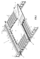
- la figure 1 est une vue en perspective d'une structure de plancher en béton du type à bacs collaborants, comprenant une trémie dont les moyens de renforcement associés sont intégrés dans l'épaisseur du plancher ;
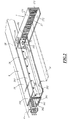
- la figure 2 est une vue en perspective partielle agrandie d'éléments de renforcement d'une trémie de plancher, du type à bacs collaborants, comportant une trémie dont les moyens de renforcement sont intégrés dans l'épaisseur du plancher;
- la figure 3 est une vue schématique d'une première disposition d'une trémie dans un plancher du type de plancher en béton du type à bacs collaborants ;
- la figure 4 est une vue schématique d'une deuxième disposition d'une trémie dans un plancher en béton du type à bacs collaborants ;
- la figure 5 est une vue schématique d'un troisième mode de disposition d'une trémie dans un plancher en béton du type à bacs collaborants ; et
- la figure 6 est une vue schématique d'une quatrième disposition d'une trémie dans un plancher en béton du type à bacs collaborants.
- Figure 1 is a perspective view of a concrete floor structure of the type cooperating tanks, comprising a hopper whose associated reinforcement means are integrated in the thickness of the floor;
- FIG. 2 is an enlarged partial perspective view of reinforcing elements of a floor hopper, of the type with cooperating containers, comprising a hopper whose reinforcing means are integrated in the thickness of the floor;
- Figure 3 is a schematic view of a first arrangement of a hopper in a floor of the type of concrete floor type collaborating bins;
- Figure 4 is a schematic view of a second arrangement of a hopper in a concrete floor of the type cooperating tanks;
- Figure 5 is a schematic view of a third mode of arrangement of a hopper in a concrete floor of the type cooperating tanks; and
- Figure 6 is a schematic view of a fourth arrangement of a hopper in a concrete floor type cooperating tanks.
La structure de plancher en béton du type à bacs collaborants 1, repérée généralement par 1 à la figure 1, est en appui sur deux appuis d'extrémité transversaux 2 constitués de poutres, ou plus généralement de toutes structures support d'un bâtiment, et par exemple de murs porteurs. Le plancher comporte une trémie 3 qui est une ouverture de dimension significative, en général supérieure à 50cm par 50cm, et destinée, par exemple, à faire déboucher un escalier.The concrete floor structure of the type with collaborative bins 1, generally denoted by 1 in FIG. 1, is supported on two transverse end supports 2 consisting of beams, or more generally of all supporting structures of a building, and for example, load-bearing walls. The floor comprises a
Cette structure de plancher en béton de type à bacs collaborants 1 est constituée d'une pluralité de bacs auto porteurs nervurés 4 s'étendant entre les poutres d'appui d'extrémité transversale 2 sur lesquelles ils reposent par leurs extrémités. Ces bacs sont des bacs auto porteurs connus en eux-mêmes dont les nervures sont en général de forme en oméga.This concrete floor structure type cooperating tanks 1 consists of a plurality of ribbed self-supporting
Ces bacs sont disposés de part et d'autre de la trémie 3.These bins are arranged on both sides of the
La structure de plancher en béton du type à bacs collaborants 1 comporte également des moyens de renforcement repérés généralement par 5, entourant la trémie 3 et assurant le renforcement du plancher autour de la trémie.The concrete floor structure of the type cooperating tanks 1 also comprises reinforcement means generally marked by 5, surrounding the
Ces éléments de renforcement 5 comprennent deux traverses longitudinales 6 s'étendant sur toute la longueur du plancher et venant en appui sur les deux poutres d'appui d'extrémité transversale 2.These reinforcing elements 5 comprise two longitudinal crosspieces 6 extending over the entire length of the floor and bearing on the two transverse end support beams 2.
Le moyen de renforcement 5 comporte également deux chevêtres 7 transversaux, venant s'appuyer sur les traverses longitudinales 6.The reinforcing means 5 also comprises two
Les chevêtres 7 sont des moyens de support pour des bacs auto porteurs nervurés 4' de longueur plus faible que les bacs 4 disposés de part et d'autre de la trémie, et qui viennent s'étendre entre d'une part une poutre d'appui d'extrémité 2 et d'autre part un chevêtre 7 de façon à fermer les zones de plancher qui se situent entre les poutres d'appui d'extrémité et les chevêtres.The
La structure du plancher comporte également des ferraillages de renforcement du béton 8 disposés dans des nervures longitudinales des bacs auto porteurs nervurés situés au voisinage des traverses longitudinales 6.The floor structure also includes reinforcement reinforcing concrete 8 arranged in longitudinal ribs ribbed self-supporting tanks located in the vicinity of the longitudinal sleepers 6.
Ces armatures de renforcement de béton 8 sont destinées à créer au voisinage des traverses longitudinales une structure de poutre en béton renforcée.These reinforcing reinforcements concrete 8 are intended to create in the vicinity of longitudinal sleepers a reinforced concrete beam structure.
La structure du plancher en béton comporte également un treillis métallique 9 s'étendant sur toute la surface et destiné à assurer une armature de la surface de la dalle en béton. Comme on l'a représenté partiellement, la structure telle qu'elle vient d'être décrite est remplie de béton de façon à former une dalle 10 sur laquelle peut être coulée une chape 11.The structure of the concrete floor also comprises a wire mesh 9 extending over the entire surface and intended to provide a reinforcement of the surface of the concrete slab. As partially shown, the structure as just described is filled with concrete so as to form a
On notera que les armatures 8 disposées dans les nervures des bacs auto porteurs, parallèlement à des traverses longitudinales, ont des extrémités qui débordent du plancher de façon à pouvoir être connectées éventuellement aux armatures de structures de supports d'extrémité du plancher.It will be noted that the reinforcements 8 arranged in the ribs of the self-supporting tanks, parallel to longitudinal crosspieces, have ends which project beyond the floor so that they may be connected possibly to the reinforcements of the end support structures of the floor.
Chaque traverse longitudinale est constituée d'un caisson principal 16 s'étendant sur toute la longueur du plancher et de deux caissons secondaires 26 s'étendant entre les appuis transversaux d'extrémité 2 et les chevêtres 7.Each longitudinal cross member consists of a
Comme représenté plus en détail à la figure 2, la traverse longitudinale 6 est constituée d'un caisson principal 16, de section en forme de U et comprenant une âme verticale 161, qui est également l'âme de la traverse, une aile horizontale inférieure 162 s'étendant à l'opposé de la trémie, sur laquelle viennent s'appuyer des bacs auto porteurs nervurés 4 s'étendant sur toute la longueur du plancher et une aile horizontale supérieure 163 s'étendant également dans une direction opposée à la trémie.As shown in more detail in FIG. 2, the longitudinal cross-member 6 consists of a
Ce premier caisson peut être constitué soit d'une seule tôle d'acier pliée ou profilée d'épaisseur comprise entre 1 et 4mm, soit, comme cela est représenté sur la figure constitué de plusieurs structures emboîtées constituées chacun d'une tôle d'épaisseur inférieure à 4mm, de façon à obtenir une traverse d'épaisseur importante tout en étant compatible avec une fabrication simple par pliage ou par profilage.This first box may consist of either a single sheet steel bent or profiled thickness between 1 and 4mm, or, as shown in the figure consisting of several nested structures each consisting of a thick sheet less than 4mm, so as to obtain a cross-member of significant thickness while being compatible with simple manufacture by folding or profiling.
La traverse longitudinale 6 comprend également un caisson secondaire 26 également en forme de U, comprenant une âme verticale 261 accolée à l'âme verticale 161 du caisson principal 16, une aile horizontale inférieure 262 orientée en direction de la trémie et une aile horizontale supérieure 263 également orientée en direction de la trémie.The longitudinal cross member 6 also comprises a U-shaped
L'âme verticale 261 du caisson secondaire 26 est de hauteur légèrement inférieure à la hauteur de l'âme verticale 161 du caisson principal 16. Les deux caissons sont rendus solidaires par une pluralité de vis auto perceuses 60.The
Le caisson secondaire 26, qui est de longueur inférieure à la longueur du plancher, s'étend entre une poutre d'appui d'extrémité transversale et le bord transversal de la trémie délimité par un chevêtre 7.The
Le chevêtre 7 est constitué également d'un caisson en U comportant une âme verticale 171 et deux ailes horizontales inférieure 172 et supérieure 173 s'étendant dans la direction opposée à la trémie.The
La hauteur de l'âme verticale 171 du caisson 17 constituant le chevêtre 7 est de hauteur identique à la hauteur de l'âme verticale 161 du caisson principal 16 de la traverse longitudinale 6.The height of the
Les différences de hauteur entre l'âme verticale 261 du caisson secondaire et l'âme verticale 171 du caisson 17 constituant le chevêtre sont adaptées pour que le caisson 17 vienne s'emboîter sur l'extrémité 26' du caisson secondaire 26 de la traverse 6. De la sorte, le chevêtre 7 est en appui vertical sur la traverse 6. Le chevêtre 7, disposé perpendiculairement à la traverse longitudinale 6, est maintenu en position sur cette traverse par l'intermédiaire d'une équerre 18 comprenant une aile 181 et une aile 182 fixées respectivement sur l'âme verticale 171 du chevêtre et l'âme verticale de la traverse 6, par l'intermédiaire de vis auto perceuses 71 et 72 respectivement.The differences in height between the
Comme on l'a indiqué précédemment, le bac auto porteur nervuré s'étendant latéralement le long de la trémie, adjacent à la traverse longitudinale, vient en appui sur l'aile horizontale inférieure 162 du caisson principal 16 qui constitue une aile horizontale d'appui des bacs auto porteurs nervurés.As previously indicated, the ribbed self-supporting vat extending laterally along the hopper, adjacent to the longitudinal beam, bears on the lower
De façon connue de l'homme du métier, le bac auto porteur nervuré est fixé sur l'aile horizontale 162 par l'intermédiaire de vis de coûturage.In a manner known to those skilled in the art, the ribbed self-supporting tank is fixed on the
Il en est de même du bac adjacent à l'autre traverse.The same is true of the ferry adjacent to the other ferry.
De la même façon, le bac auto porteur nervuré 4' disposé entre les poutres d'appui d'extrémité transversale et les chevêtres adjacents à la traverse 6 vient en appui sur l'aile inférieure 262 du caisson secondaire 261 de la traverse longitudinale 6, sur laquelle il est fixé par des vis de coûturage, et également sur l'aile inférieure 172 du chevêtre 7 sur lequel il repose par l'une des extrémités, et sur lequel il est fixé par vis de coûturage.In the same way, the ribbed self-supporting tank 4 'disposed between the transverse end support beams and the headers adjacent to the crossmember 6 bears on the
Bien évidemment, les bacs qui s'étendent le long de l'autre traverse reposent de la même façon sur les ailes inférieures de la traverse ou du chevêtre.Of course, the bins that extend along the other cross rests in the same way on the lower wings of the crossbar or the trimmer.
Enfin, tous les bacs sont fixés par de vis de coûturage, sur les ailes inférieures sur lesquels ils reposent.Finally, all the tanks are fixed by screws of costuring, on the lower wings on which they rest.
Les hauteurs des âmes verticales 161 et 171 d'une part du caisson principal de la traverse longitudinale et d'autre part du chevêtre, sont égales à l'épaisseur du plancher en béton de telle sorte que les éléments de renforcement constituent des éléments de coffrage autour de la trémie qui délimitent le béton autour de cette trémie et arrêtent le béton au moment où il est coulé pour réaliser la dalle. En outre, la partie de ces âmes qui est située autour de la trémie délimite de façon précise la trémie.The heights of the
Les éléments de renforcement qui viennent d'être décrits sont constitués de caissons de section en U qui sont assemblés. Mais d'autres modes de réalisation sont possibles. En particulier, les caissons en U peuvent être remplacés par des caissons à section en L comportant uniquement une âme verticale et une aile horizontale inférieure.The reinforcing elements which have just been described consist of U-section boxes which are assembled. But other embodiments are possible. In particular, the U-shaped boxes can be replaced by L-section boxes having only a vertical core and a lower horizontal flange.
En effet, l'aile supérieure horizontale n'est pas nécessairement indispensable pour obtenir une bonne délimitation des trémies dans le plancher en béton.Indeed, the horizontal upper wing is not necessarily essential to obtain a good delimitation of the hoppers in the concrete floor.
Bien évidemment, lorsque les caissons ont une section en L et non pas en U, le caisson qui constitue le chevêtre doit être disposé de telle sorte que son aile inférieure vient en appui sur l'aile inférieure du caisson secondaire qui constitue la traverse longitudinale.Of course, when the caissons have a section L and not U, the box that constitutes the trimmer must be arranged so that its lower flange bears on the lower flange of the secondary box which is the longitudinal cross.
De même, les moyens de liaison entre la traverse longitudinale et le chevêtre peuvent être de tous types et ne sont pas nécessairement des équerres.Similarly, the connecting means between the longitudinal cross member and the treader may be of any type and are not necessarily brackets.
Les caissons, dont sont constitués des éléments de renforcement du plancher autour de la trémie, sont des caissons métalliques obtenus par pliage ou profilage de tôles métalliques d'épaisseur comprise entre 1 et 4mm. Cette épaisseur est limitée de façon à permettre un pliage et/ou un profilage dans les conditions satisfaisantes pour pouvoir être réalisées à proximité d'un chantier.The boxes, which consist of reinforcing elements of the floor around the hopper, are metal boxes obtained by folding or profiling of metal sheets with a thickness between 1 and 4mm. This thickness is limited so as to allow folding and / or profiling under satisfactory conditions to be carried out near a site.
Néanmoins, il peut être souhaitable d'utiliser des éléments de renforcement ayant des propriétés mécaniques plus importantes que celles que l'on peut obtenir avec des tôles d'épaisseur allant jusqu'à 4mm.Nevertheless, it may be desirable to use reinforcing elements having greater mechanical properties than those which can be obtained with sheets up to 4 mm thick.
Aussi, pour obtenir des éléments de renforcement plus massifs, on peut réaliser ces éléments de renforcement en emboîtant une pluralité de caissons ayant des formes adaptées de façon à pouvoir être emboîtés les uns dans les autres. En procédant ainsi, on obtient des structures feuilletées pouvant avoir des épaisseurs beaucoup plus importantes que des épaisseurs de 4mm.Also, to obtain more massive reinforcing elements, one can realize these reinforcing elements by fitting a plurality of boxes having shapes adapted to be nested in each other. By doing so, we obtain laminated structures that can have much greater thicknesses than thicknesses of 4mm.
Ces éléments de renforcement peuvent être en acier nu ou en acier galvanisé, de façon à pouvoir être protégés contre la corrosion.These reinforcing elements can be made of bare steel or galvanized steel, so that they can be protected against corrosion.
Comme représentées aux figures 3 à 6, quatre configurations peuvent être envisagées.As shown in Figures 3 to 6, four configurations can be envisaged.
Dans une première configuration, représentée à la figure 3, la trémie 100 est disposée dans la partie centrale du plancher et est délimitée par deux traverses longitudinales 103 et 104 en appui sur des appuis d'extrémité transversaux 101 et 102, et par deux chevêtres 105 et 106 en appui chacun sur les traverses longitudinales 103 et 104.In a first configuration, shown in Figure 3, the
Dans cette disposition, chaque traverse longitudinale 103, 104 est constituée d'un caisson principal 113, 114 respectivement, et de deux caissons secondaires 123, 123' et 124, 124' respectivement.In this arrangement, each
Dans une deuxième disposition, représentée à la figure 4, la trémie 200 est disposée contre un des appuis d'extrémité transversal 201 du plancher.In a second arrangement, shown in Figure 4, the
Le plancher repose sur deux appuis d'extrémité transversaux 201, 202, et la trémie 200 est délimitée d'une part par l'un des appui d'extrémité transversal 201 du plancher et par deux traverses longitudinales 203 et 204 qui s'appuient chacune sur les deux appuis d'extrémité transversaux 201 et 202 du plancher, et par un seul chevêtre 205 en appui sur les deux traverses longitudinales.The floor rests on two transverse end supports 201, 202, and the
Dans cette disposition, chaque traverse longitudinale 203, 204 est constituée d'un caisson principal 213 et 214, respectivement, et d'un seul caisson secondaire 223 et 224 respectivement.In this arrangement, each
Dans une troisième disposition, représentée à la figure 5, la trémie 300 est disposée à une certaine distance de chacun des appuis d'extrémité transversaux du plancher, mais est délimitée latéralement d'un côté par un appui longitudinal 304 du plancher.In a third arrangement, shown in Figure 5, the
Dans cette disposition la trémie 300 est délimitée d'une part par un appui longitudinal 304 du plancher, par une traverse longitudinale 303 qui s'appuie sur les deux appuis d'extrémité transversaux 301 et 302 du plancher et par deux chevêtres 305 et 306 qui s'appuient d'une part sur la traverse longitudinale 303 et d'autre part sur l'appui longitudinal 304 du plancher.In this arrangement the
Dans cette disposition, la traverse 303 est constituée d'un caisson principal 313 et de deux caissons secondaires 323 et 323'.In this arrangement, the
Dans une quatrième disposition, le plancher s'appuie sur trois appuis, deux appuis d'extrémité transversaux 401 et 402 et un appui longitudinal 404, et la trémie 400 est disposée dans un coin délimité par l'un des appuis d'extrémité transversaux 401, et par l'appui longitudinal 404.In a fourth arrangement, the floor rests on three supports, two transverse end supports 401 and 402 and a
La trémie est délimitée en outre par une seule traverse longitudinale 403 qui s'appuie sur les deux appuis d'extrémité transversaux 401 et 402, et par un chevêtre 405 qui s'appuie d'une part sur la traverse longitudinale 403 et d'autre part sur l'appui longitudinal 404 du plancher.The hopper is further delimited by a single
Dans cette disposition, la traverse 413 est constituée d'un seul caisson principal 413 et d'un seul caisson secondaire 423.In this arrangement, the
On constate que, dans ces différentes dispositions, une traverse longitudinale comporte un seul caisson principal mais selon que la structure prévoit un seul chevêtre ou deux chevêtres, chaque traverse longitudinale comporte un ou deux caissons secondaires.It can be seen that, in these different arrangements, a longitudinal cross member has only one main box, but depending on whether the structure provides for a single header or two headers, each longitudinal cross member has one or two secondary boxes.
Dans les modes de réalisation qui viennent d'être décrits, le plancher comporte une seule trémie délimitée par deux traverses longitudinales. Mais, on peut envisager des structures dans lesquelles les distances entre les deux appuis d'extrémité transversaux du plancher sont suffisantes pour que l'on puisse disposer entre ces deux appuis plusieurs trémies disposées entre deux traverses longitudinales, et délimitées chacune par un couple de chevêtre.In the embodiments which have just been described, the floor comprises a single hopper delimited by two longitudinal crosspieces. But, one can envisage structures in which the distances between the two transverse end supports of the floor are sufficient so that one can have between these two supports several hoppers arranged between two longitudinal crosspieces, and each delimited by a couple of trimmer .
Afin de pouvoir réaliser commodément des planchers collaborants comportant des chevêtres, les éléments d'armature de chevêtre incorporés dans l'épaisseur du plancher, peuvent être préparés sous forme de kits qui peuvent être mis à la disposition des entrepreneurs pour réaliser autant que de besoin les trémies qu'il souhaite obtenir.In order to be able to conveniently produce cooperating floors with trimmers, the truss elements incorporated in the thickness of the floor, can be prepared as kits that can be made available to contractors to achieve as much as necessary. hoppers he wants to get.
Ces kits sont constitués de caissons principaux destinés à réaliser des traverses longitudinales, de caissons secondaires destinés à compléter les traverses longitudinales, de caissons destinés à réaliser les chevêtres, d'équerres ou plus généralement de moyens de liaison des chevêtres avec les traverses longitudinales, et enfin, de vis auto perceuses destinées à l'assemblage des différentes composantes de l'armature.These kits consist of main boxes for making longitudinal sleepers, secondary boxes for completing the longitudinal sleepers, boxes for making the trimmers, brackets or more generally means for connecting the headers with the longitudinal struts, and and finally, self-drilling screws for assembling the different components of the frame.
Les différentes composantes des caissons peuvent être coupées à longueur par l'utilisateur pour les adapter à chaque cas particulier.The different components of the boxes can be cut to length by the user to adapt to each particular case.
Ces caissons peuvent être soient des caissons constitués d'une seule tôle, soit des caissons constitués de plusieurs caissons élémentaires emboîtables qui peuvent être soit emboîtés directement avant mise à disposition de l'utilisateur, ou soit qui peuvent être mis à la disposition de l'utilisateur sous forme d'une série de caissons pouvant être emboîtés.These boxes can be either caissons consisting of a single sheet, or boxes consisting of several nestable elementary boxes that can be either nested directly before provision to the user, or that can be made available to the user. user in the form of a series of casings that can be nested.
Les kits, qui viennent d'être décrits de façon générale, peuvent être présentés sous différentes formes pour être adaptés aux quatre cas de réalisation qui viennent d'être décrit. Ainsi, les kits peuvent comporter un ou deux ensembles destinés à réaliser des traverses longitudinales, et un ou deux ensembles destinés à réaliser des chevêtres.Kits, which have just been described in general, can be presented in different forms to be adapted to the four embodiments described above. Thus, the kits may include one or two sets for making longitudinal sleepers, and one or two sets for making trimmers.
Les traverses longitudinales ont des longueurs standard qui sont égales aux longueurs standard des bacs auto porteurs nervurés. Si il existe plusieurs longueurs standard de bacs auto porteurs nervurés, on peut envisager des kits correspondant à chacune des longueurs standard de bacs auto porteurs nervurés.Longitudinal sleepers have standard lengths that are equal to the standard lengths of ribbed self-supporting bins. If there are several standard lengths of ribbed self-supporting tanks, kits corresponding to each of the standard lengths of ribbed self-supporting tanks can be envisaged.
Pour réaliser un plancher en béton du type collaborant, comportant une trémie, l'utilisateur commence par préparer une ou deux traverses longitudinales selon la disposition de la trémie qu'il souhaite réaliser.To achieve a concrete floor of the collaborative type, comprising a hopper, the user begins by preparing one or two longitudinal cross members according to the disposition of the hopper he wishes to achieve.
Pour réaliser ces traverses longitudinales, l'utilisateur découpe des deuxièmes caissons à des longueurs adaptées et fixe les deuxièmes caissons sur le ou les premiers caissons de façon à constituer une ou deux traverses ayant une géométrie adaptée à la trémie qu'il souhaite réaliser.To achieve these longitudinal sleepers, the user cuts second boxes to suitable lengths and fixed the second boxes on the first or boxes so as to form one or two sleepers having a geometry adapted to the hopper he wishes to achieve.
Une fois qu'il a préparé les traverses longitudinales, sur lesquelles il a fixé au préalable les équerres de fixation des chevêtres, l'utilisateur met en place les bacs nervurés de part et d'autre des bords latéraux de la trémie, puis met en place la ou les traverses qui vont délimiter la trémie et qui vont assurer le support de l'ensemble.Once he has prepared the longitudinal sleepers, on which he has previously fixed the anchor brackets, the user sets up the ribbed trays on both sides of the side of the hopper, then sets place the sleepers or rails that will delimit the hopper and will ensure the support of the whole.
L'utilisateur met alors en place les bacs nervurés correspondant aux portions de plancher disposées entre les traverses. Ces bacs nervurés ont des longueurs inférieures aux longueurs des bacs nervurés qui s'étendent entre les deux appuis d'extrémité latéraux du plancher. De façon à pouvoir mettre en place ces bacs nervurés, l'utilisateur procède comme cela est connu de l'homme du métier, par exemple en assurant le soutènement provisoire des bacs.The user then sets up the ribbed trays corresponding to the floor portions disposed between the sleepers. These ribbed tanks have lengths less than the lengths of the ribbed trays that extend between the two lateral end supports of the floor. In order to be able to set up these ribbed trays, the user proceeds as is known to those skilled in the art, for example by providing temporary support tanks.
Puis, l'utilisateur met en place le ou les chevêtres qu'il fixe par l'intermédiaire des équerres de fixation sur les traverses longitudinales. Lorsqu'il met en place ces chevêtres, l'utilisateur les dispose de façon telle que les bacs nervurés correspondant aux portions de plancher entre les traverses viennent en appui sur l'aile inférieure des chevêtres.Then, the user sets up the one or more headers that he fixes through the fastening brackets on the longitudinal crosspieces. When he sets up these trimmers, the user arranges them in such a way that the ribbed trays corresponding to the floor portions between the struts bear against the lower wing of the trimmers.
L'utilisateur vérifie alors l'équerrage de l'ensemble et fixe les traverses sur les appuis transversaux d'extrémité et fixe les différents bacs sur les traverses et sur les chevêtres à l'aide de vis de coûturage.The user then checks the squareness of the assembly and fixes the cross members on the transverse end supports and fixes the different bins on the sleepers and on the headers with the aid of costing screws.
Eventuellement, l'utilisateur met en place dans les nervures qui jouxtent les traverses longitudinales les armatures complémentaires qui sont destinées à réaliser des poutres en béton de support du plancher. En effet, l'utilisateur peut, soit ne pas prévoir de ferraillage complémentaire dans les nervures des bacs auto porteurs nervurés, soit prévoir une seule armature de chaque côté de la trémie, soit prévoir éventuellement des armatures dans plusieurs nervures adjacentes. La présence ou l'absence ainsi que l'importance des ferraillages, de même que les épaisseurs des éléments de renforcement sont choisis par l'homme du métier en fonction des indications données par la note de calcul relative à l'ouvrage considéré.Optionally, the user puts in place in the ribs adjacent to the longitudinal sleepers additional reinforcements which are intended to make concrete beams supporting the floor. Indeed, the user may either not provide additional reinforcement in the ribs self-carrier vane racks, or provide a single frame on each side of the hopper, or possibly provide reinforcements in several adjacent ribs. The presence or absence as well as the importance of reinforcement, as well as the thicknesses of the reinforcing elements are chosen by the skilled person according to the indications given by the calculation note relating to the work in question.
Une fois que l'utilisateur a mis en place les armatures destinées à réaliser la trémie, il poursuit la réalisation de son plancher selon les méthodes habituelles connues de l'homme du métier.Once the user has set up the reinforcements for making the hopper, he continues to build his floor according to the usual methods known to those skilled in the art.
Dans les modes de réalisation qui viennent d'être décrits, les éléments de renforcement sont constitués de caissons en U, mais l'homme du métier comprend qu'il pourra utiliser des profilés de formes différentes, par exemple en L, pourvu que les fonctions de poutre, de soutien des bacs nervurés et de liaison soient assurées.In the embodiments which have just been described, the reinforcing elements consist of U-shaped boxes, but the person skilled in the art understands that he will be able to use profiles of different shapes, for example in L, provided that the functions beam, support ribs and binding are insured.
En outre, les fixations par des vis auto perceuses peuvent être remplacées par tout moyen de fixation adapté que l'homme du métier saura choisir.In addition, the fasteners by self-drilling screws may be replaced by any suitable fastening means that the skilled person will choose.
Claims (21)
Priority Applications (5)
| Application Number | Priority Date | Filing Date | Title |
|---|---|---|---|
| PL06290848T PL1860251T3 (en) | 2006-05-24 | 2006-05-24 | Concrete floor of the type with with collaborative form-slabs having an opening and building kit for realizing said opening |
| PT06290848T PT1860251E (en) | 2006-05-24 | 2006-05-24 | Concrete floor of the type with with collaborative form-slabs having an opening and building kit for realizing said opening |
| EP06290848A EP1860251B1 (en) | 2006-05-24 | 2006-05-24 | Concrete floor of the type with with collaborative form-slabs having an opening and building kit for realizing said opening |
| AT06290848T ATE529582T1 (en) | 2006-05-24 | 2006-05-24 | CONCRETE CEILING WITH COOPERATIVE FORMWORK PANELS WITH AN OPENING AND KIT TO CREATE THIS OPENING |
| ES06290848T ES2375996T3 (en) | 2006-05-24 | 2006-05-24 | CONCRETE FLOOR, OF THE TYPE OF COLLABORATING MOLDS THAT INCLUDES A BOX OF REINFORCEMENT MEANS FOR THE REALIZATION OF THE BOX. |
Applications Claiming Priority (1)
| Application Number | Priority Date | Filing Date | Title |
|---|---|---|---|
| EP06290848A EP1860251B1 (en) | 2006-05-24 | 2006-05-24 | Concrete floor of the type with with collaborative form-slabs having an opening and building kit for realizing said opening |
Publications (2)
| Publication Number | Publication Date |
|---|---|
| EP1860251A1 true EP1860251A1 (en) | 2007-11-28 |
| EP1860251B1 EP1860251B1 (en) | 2011-10-19 |
Family
ID=37564180
Family Applications (1)
| Application Number | Title | Priority Date | Filing Date |
|---|---|---|---|
| EP06290848A Active EP1860251B1 (en) | 2006-05-24 | 2006-05-24 | Concrete floor of the type with with collaborative form-slabs having an opening and building kit for realizing said opening |
Country Status (5)
| Country | Link |
|---|---|
| EP (1) | EP1860251B1 (en) |
| AT (1) | ATE529582T1 (en) |
| ES (1) | ES2375996T3 (en) |
| PL (1) | PL1860251T3 (en) |
| PT (1) | PT1860251E (en) |
Cited By (3)
| Publication number | Priority date | Publication date | Assignee | Title |
|---|---|---|---|---|
| EP2304121A1 (en) * | 2008-06-13 | 2011-04-06 | Bluescope Steel Limited | Panel assembly, composite panel and components for use in same |
| CN114934621A (en) * | 2022-07-21 | 2022-08-23 | 中国船舶重工集团国际工程有限公司 | Composite floor system for box plate assembly type building and installation method thereof |
| WO2023170375A1 (en) | 2022-03-08 | 2023-09-14 | MCP Group Limited | Riser assembly |
Citations (3)
| Publication number | Priority date | Publication date | Assignee | Title |
|---|---|---|---|---|
| GB2265640A (en) * | 1992-03-31 | 1993-10-06 | Halfen Fixing Systems Limited | Pour stop for concrete structure |
| US5941035A (en) * | 1997-09-03 | 1999-08-24 | Mega Building System Ltd. | Steel joist and concrete floor system |
| NL1020123C1 (en) * | 2002-03-07 | 2003-09-12 | Bat Continental B V | Lost edge shuttering, comprises single piece profile for contact with liquid concrete and anchor devices securable to inside of profile via temporary fasteners |
-
2006
- 2006-05-24 AT AT06290848T patent/ATE529582T1/en not_active IP Right Cessation
- 2006-05-24 PT PT06290848T patent/PT1860251E/en unknown
- 2006-05-24 EP EP06290848A patent/EP1860251B1/en active Active
- 2006-05-24 ES ES06290848T patent/ES2375996T3/en active Active
- 2006-05-24 PL PL06290848T patent/PL1860251T3/en unknown
Patent Citations (3)
| Publication number | Priority date | Publication date | Assignee | Title |
|---|---|---|---|---|
| GB2265640A (en) * | 1992-03-31 | 1993-10-06 | Halfen Fixing Systems Limited | Pour stop for concrete structure |
| US5941035A (en) * | 1997-09-03 | 1999-08-24 | Mega Building System Ltd. | Steel joist and concrete floor system |
| NL1020123C1 (en) * | 2002-03-07 | 2003-09-12 | Bat Continental B V | Lost edge shuttering, comprises single piece profile for contact with liquid concrete and anchor devices securable to inside of profile via temporary fasteners |
Cited By (4)
| Publication number | Priority date | Publication date | Assignee | Title |
|---|---|---|---|---|
| EP2304121A1 (en) * | 2008-06-13 | 2011-04-06 | Bluescope Steel Limited | Panel assembly, composite panel and components for use in same |
| EP2304121A4 (en) * | 2008-06-13 | 2013-11-27 | Bluescope Steel Ltd | Panel assembly, composite panel and components for use in same |
| WO2023170375A1 (en) | 2022-03-08 | 2023-09-14 | MCP Group Limited | Riser assembly |
| CN114934621A (en) * | 2022-07-21 | 2022-08-23 | 中国船舶重工集团国际工程有限公司 | Composite floor system for box plate assembly type building and installation method thereof |
Also Published As
| Publication number | Publication date |
|---|---|
| EP1860251B1 (en) | 2011-10-19 |
| PL1860251T3 (en) | 2012-03-30 |
| PT1860251E (en) | 2011-12-19 |
| ES2375996T3 (en) | 2012-03-08 |
| ATE529582T1 (en) | 2011-11-15 |
Similar Documents
| Publication | Publication Date | Title |
|---|---|---|
| EP1941104B1 (en) | New type of building, method and means for erecting it | |
| BE679420A (en) | ||
| EP1860251B1 (en) | Concrete floor of the type with with collaborative form-slabs having an opening and building kit for realizing said opening | |
| EP0285465B1 (en) | Structural element, especially a facing element with integrated insulation | |
| FR2950638A1 (en) | Constructive system for building, has wall elements equipped with two concrete strips spaced and connected together by vertical spacers, where parts of strips blades external to spacers form walls of slide boxes of framework of building | |
| FR2560621A1 (en) | Rib element and slab made up of such elements, as well as the method of manufacture of these elements and the means for implementing this method. | |
| WO2009092890A2 (en) | Prefabricated modular dry-floor element, method of producing such a modular element and dry floor comprising a plurality of modular elements | |
| FR2913993A1 (en) | Interjoist i.e. slab, for constructing building floor, has shoulder whose plane part rests on upper faces of flanges of adjacent girders, where lower part of shoulder is supported on side faces of flanges to obtain spacing between girders | |
| EP0767282B1 (en) | Collaborating metallic girder | |
| EP0891458B1 (en) | Construction, panel therefor and method for making same | |
| EP0271400A1 (en) | Façade covering with a ventilated-air layer | |
| EP2844809B1 (en) | Formwork and associated floor | |
| FR2938856A1 (en) | PREFABRICATED CONCRETE PANEL, AND METHOD FOR IMPLEMENTING SUCH PANEL IN FLOOR FRAMEWORK | |
| EP2444567B1 (en) | Formwork element for building a beam | |
| EP1380703B1 (en) | Trimmer construction for a floor built up from plate-shaped elements, and a trimmer accessory to be used therewith | |
| FR2729411A3 (en) | Flooring reinforced concrete coffering slab | |
| EP4343079A2 (en) | Wall connection fitting with integrated formwork | |
| FR2474083A1 (en) | Pre-fabricated reinforced beam for floors in building renovation - has overlapping vertical stirrups to increase I-section of reinforcing bars | |
| FR2768758A1 (en) | Insulating panel for building roof | |
| FR3105276A1 (en) | Ladder-of-link | |
| FR2718776A1 (en) | Shuttering panel for concrete | |
| EP0533647A1 (en) | Mixed construction wall and profiled sheet metal for such a wall | |
| FR3019193A1 (en) | MODULAR BRIDGE TRACK, BEAM MODULE AND METHOD OF MODULAR CONSTRUCTION OF SUCH A WORK | |
| FR2904643A1 (en) | Removable wall covering module for facade of building, has plates assembly assembled on thin support structure, and gripping unit pre-arranged in mass of support structure and cooperating with fixing unit that is integrated to wall | |
| BE463285A (en) |
Legal Events
| Date | Code | Title | Description |
|---|---|---|---|
| PUAI | Public reference made under article 153(3) epc to a published international application that has entered the european phase |
Free format text: ORIGINAL CODE: 0009012 |
|
| AK | Designated contracting states |
Kind code of ref document: A1 Designated state(s): AT BE BG CH CY CZ DE DK EE ES FI FR GB GR HU IE IS IT LI LT LU LV MC NL PL PT RO SE SI SK TR |
|
| AX | Request for extension of the european patent |
Extension state: AL BA HR MK YU |
|
| 17P | Request for examination filed |
Effective date: 20080307 |
|
| AKX | Designation fees paid |
Designated state(s): AT BE BG CH CY CZ DE DK EE ES FI FR GB GR HU IE IS IT LI LT LU LV MC NL PL PT RO SE SI SK TR |
|
| AXX | Extension fees paid |
Extension state: AL Payment date: 20080307 Extension state: YU Payment date: 20080307 Extension state: MK Payment date: 20080307 Extension state: BA Payment date: 20080307 Extension state: HR Payment date: 20080307 |
|
| 17Q | First examination report despatched |
Effective date: 20101222 |
|
| GRAP | Despatch of communication of intention to grant a patent |
Free format text: ORIGINAL CODE: EPIDOSNIGR1 |
|
| GRAS | Grant fee paid |
Free format text: ORIGINAL CODE: EPIDOSNIGR3 |
|
| RAP1 | Party data changed (applicant data changed or rights of an application transferred) |
Owner name: ARCELORMITTAL CONSTRUCTION FRANCE |
|
| GRAA | (expected) grant |
Free format text: ORIGINAL CODE: 0009210 |
|
| AK | Designated contracting states |
Kind code of ref document: B1 Designated state(s): AT BE BG CH CY CZ DE DK EE ES FI FR GB GR HU IE IS IT LI LT LU LV MC NL PL PT RO SE SI SK TR |
|
| AX | Request for extension of the european patent |
Extension state: AL BA HR MK YU |
|
| REG | Reference to a national code |
Ref country code: GB Ref legal event code: FG4D Free format text: NOT ENGLISH |
|
| REG | Reference to a national code |
Ref country code: CH Ref legal event code: EP |
|
| REG | Reference to a national code |
Ref country code: IE Ref legal event code: FG4D |
|
| REG | Reference to a national code |
Ref country code: PT Ref legal event code: SC4A Free format text: AVAILABILITY OF NATIONAL TRANSLATION Effective date: 20111129 |
|
| REG | Reference to a national code |
Ref country code: NL Ref legal event code: T3 |
|
| REG | Reference to a national code |
Ref country code: DE Ref legal event code: R096 Ref document number: 602006025188 Country of ref document: DE Effective date: 20111222 |
|
| REG | Reference to a national code |
Ref country code: ES Ref legal event code: FG2A Ref document number: 2375996 Country of ref document: ES Kind code of ref document: T3 Effective date: 20120308 |
|
| LTIE | Lt: invalidation of european patent or patent extension |
Effective date: 20111019 |
|
| REG | Reference to a national code |
Ref country code: PL Ref legal event code: T3 |
|
| REG | Reference to a national code |
Ref country code: AT Ref legal event code: MK05 Ref document number: 529582 Country of ref document: AT Kind code of ref document: T Effective date: 20111019 |
|
| PG25 | Lapsed in a contracting state [announced via postgrant information from national office to epo] |
Ref country code: IS Free format text: LAPSE BECAUSE OF FAILURE TO SUBMIT A TRANSLATION OF THE DESCRIPTION OR TO PAY THE FEE WITHIN THE PRESCRIBED TIME-LIMIT Effective date: 20120219 Ref country code: LT Free format text: LAPSE BECAUSE OF FAILURE TO SUBMIT A TRANSLATION OF THE DESCRIPTION OR TO PAY THE FEE WITHIN THE PRESCRIBED TIME-LIMIT Effective date: 20111019 |
|
| REG | Reference to a national code |
Ref country code: IE Ref legal event code: FD4D |
|
| PG25 | Lapsed in a contracting state [announced via postgrant information from national office to epo] |
Ref country code: SE Free format text: LAPSE BECAUSE OF FAILURE TO SUBMIT A TRANSLATION OF THE DESCRIPTION OR TO PAY THE FEE WITHIN THE PRESCRIBED TIME-LIMIT Effective date: 20111019 Ref country code: SI Free format text: LAPSE BECAUSE OF FAILURE TO SUBMIT A TRANSLATION OF THE DESCRIPTION OR TO PAY THE FEE WITHIN THE PRESCRIBED TIME-LIMIT Effective date: 20111019 Ref country code: GR Free format text: LAPSE BECAUSE OF FAILURE TO SUBMIT A TRANSLATION OF THE DESCRIPTION OR TO PAY THE FEE WITHIN THE PRESCRIBED TIME-LIMIT Effective date: 20120120 Ref country code: LV Free format text: LAPSE BECAUSE OF FAILURE TO SUBMIT A TRANSLATION OF THE DESCRIPTION OR TO PAY THE FEE WITHIN THE PRESCRIBED TIME-LIMIT Effective date: 20111019 |
|
| PG25 | Lapsed in a contracting state [announced via postgrant information from national office to epo] |
Ref country code: CY Free format text: LAPSE BECAUSE OF FAILURE TO SUBMIT A TRANSLATION OF THE DESCRIPTION OR TO PAY THE FEE WITHIN THE PRESCRIBED TIME-LIMIT Effective date: 20111019 |
|
| PG25 | Lapsed in a contracting state [announced via postgrant information from national office to epo] |
Ref country code: DK Free format text: LAPSE BECAUSE OF FAILURE TO SUBMIT A TRANSLATION OF THE DESCRIPTION OR TO PAY THE FEE WITHIN THE PRESCRIBED TIME-LIMIT Effective date: 20111019 Ref country code: CZ Free format text: LAPSE BECAUSE OF FAILURE TO SUBMIT A TRANSLATION OF THE DESCRIPTION OR TO PAY THE FEE WITHIN THE PRESCRIBED TIME-LIMIT Effective date: 20111019 Ref country code: SK Free format text: LAPSE BECAUSE OF FAILURE TO SUBMIT A TRANSLATION OF THE DESCRIPTION OR TO PAY THE FEE WITHIN THE PRESCRIBED TIME-LIMIT Effective date: 20111019 Ref country code: BG Free format text: LAPSE BECAUSE OF FAILURE TO SUBMIT A TRANSLATION OF THE DESCRIPTION OR TO PAY THE FEE WITHIN THE PRESCRIBED TIME-LIMIT Effective date: 20120119 Ref country code: IE Free format text: LAPSE BECAUSE OF FAILURE TO SUBMIT A TRANSLATION OF THE DESCRIPTION OR TO PAY THE FEE WITHIN THE PRESCRIBED TIME-LIMIT Effective date: 20111019 Ref country code: EE Free format text: LAPSE BECAUSE OF FAILURE TO SUBMIT A TRANSLATION OF THE DESCRIPTION OR TO PAY THE FEE WITHIN THE PRESCRIBED TIME-LIMIT Effective date: 20111019 |
|
| PLBE | No opposition filed within time limit |
Free format text: ORIGINAL CODE: 0009261 |
|
| STAA | Information on the status of an ep patent application or granted ep patent |
Free format text: STATUS: NO OPPOSITION FILED WITHIN TIME LIMIT |
|
| PG25 | Lapsed in a contracting state [announced via postgrant information from national office to epo] |
Ref country code: RO Free format text: LAPSE BECAUSE OF FAILURE TO SUBMIT A TRANSLATION OF THE DESCRIPTION OR TO PAY THE FEE WITHIN THE PRESCRIBED TIME-LIMIT Effective date: 20111019 Ref country code: IT Free format text: LAPSE BECAUSE OF FAILURE TO SUBMIT A TRANSLATION OF THE DESCRIPTION OR TO PAY THE FEE WITHIN THE PRESCRIBED TIME-LIMIT Effective date: 20111019 |
|
| 26N | No opposition filed |
Effective date: 20120720 |
|
| REG | Reference to a national code |
Ref country code: DE Ref legal event code: R097 Ref document number: 602006025188 Country of ref document: DE Effective date: 20120720 |
|
| BERE | Be: lapsed |
Owner name: ARCELORMITTAL CONSTRUCTION FRANCE Effective date: 20120531 |
|
| REG | Reference to a national code |
Ref country code: NL Ref legal event code: V1 Effective date: 20121201 |
|
| PG25 | Lapsed in a contracting state [announced via postgrant information from national office to epo] |
Ref country code: MC Free format text: LAPSE BECAUSE OF NON-PAYMENT OF DUE FEES Effective date: 20120531 |
|
| REG | Reference to a national code |
Ref country code: CH Ref legal event code: PL |
|
| GBPC | Gb: european patent ceased through non-payment of renewal fee |
Effective date: 20120524 |
|
| PG25 | Lapsed in a contracting state [announced via postgrant information from national office to epo] |
Ref country code: LI Free format text: LAPSE BECAUSE OF NON-PAYMENT OF DUE FEES Effective date: 20120531 Ref country code: CH Free format text: LAPSE BECAUSE OF NON-PAYMENT OF DUE FEES Effective date: 20120531 Ref country code: AT Free format text: LAPSE BECAUSE OF FAILURE TO SUBMIT A TRANSLATION OF THE DESCRIPTION OR TO PAY THE FEE WITHIN THE PRESCRIBED TIME-LIMIT Effective date: 20111019 |
|
| PG25 | Lapsed in a contracting state [announced via postgrant information from national office to epo] |
Ref country code: BE Free format text: LAPSE BECAUSE OF NON-PAYMENT OF DUE FEES Effective date: 20120531 |
|
| REG | Reference to a national code |
Ref country code: FR Ref legal event code: ST Effective date: 20130131 |
|
| REG | Reference to a national code |
Ref country code: PT Ref legal event code: MM4A Free format text: LAPSE DUE TO NON-PAYMENT OF FEES Effective date: 20130225 |
|
| REG | Reference to a national code |
Ref country code: DE Ref legal event code: R119 Ref document number: 602006025188 Country of ref document: DE Effective date: 20121201 |
|
| PG25 | Lapsed in a contracting state [announced via postgrant information from national office to epo] |
Ref country code: NL Free format text: LAPSE BECAUSE OF NON-PAYMENT OF DUE FEES Effective date: 20121201 |
|
| PG25 | Lapsed in a contracting state [announced via postgrant information from national office to epo] |
Ref country code: FR Free format text: LAPSE BECAUSE OF NON-PAYMENT OF DUE FEES Effective date: 20120531 Ref country code: GB Free format text: LAPSE BECAUSE OF NON-PAYMENT OF DUE FEES Effective date: 20120524 |
|
| PG25 | Lapsed in a contracting state [announced via postgrant information from national office to epo] |
Ref country code: PT Free format text: LAPSE BECAUSE OF NON-PAYMENT OF DUE FEES Effective date: 20130225 |
|
| PG25 | Lapsed in a contracting state [announced via postgrant information from national office to epo] |
Ref country code: FI Free format text: LAPSE BECAUSE OF FAILURE TO SUBMIT A TRANSLATION OF THE DESCRIPTION OR TO PAY THE FEE WITHIN THE PRESCRIBED TIME-LIMIT Effective date: 20111019 Ref country code: DE Free format text: LAPSE BECAUSE OF NON-PAYMENT OF DUE FEES Effective date: 20121201 |
|
| REG | Reference to a national code |
Ref country code: ES Ref legal event code: FD2A Effective date: 20130820 |
|
| PG25 | Lapsed in a contracting state [announced via postgrant information from national office to epo] |
Ref country code: PL Free format text: LAPSE BECAUSE OF NON-PAYMENT OF DUE FEES Effective date: 20120524 |
|
| REG | Reference to a national code |
Ref country code: PL Ref legal event code: LAPE |
|
| PG25 | Lapsed in a contracting state [announced via postgrant information from national office to epo] |
Ref country code: ES Free format text: LAPSE BECAUSE OF NON-PAYMENT OF DUE FEES Effective date: 20120525 |
|
| PG25 | Lapsed in a contracting state [announced via postgrant information from national office to epo] |
Ref country code: TR Free format text: LAPSE BECAUSE OF FAILURE TO SUBMIT A TRANSLATION OF THE DESCRIPTION OR TO PAY THE FEE WITHIN THE PRESCRIBED TIME-LIMIT Effective date: 20111019 |
|
| PG25 | Lapsed in a contracting state [announced via postgrant information from national office to epo] |
Ref country code: LU Free format text: LAPSE BECAUSE OF NON-PAYMENT OF DUE FEES Effective date: 20120524 |
|
| PG25 | Lapsed in a contracting state [announced via postgrant information from national office to epo] |
Ref country code: HU Free format text: LAPSE BECAUSE OF FAILURE TO SUBMIT A TRANSLATION OF THE DESCRIPTION OR TO PAY THE FEE WITHIN THE PRESCRIBED TIME-LIMIT Effective date: 20060524 |