EP1850462A2 - Épurateur - Google Patents
Épurateur Download PDFInfo
- Publication number
- EP1850462A2 EP1850462A2 EP07114395A EP07114395A EP1850462A2 EP 1850462 A2 EP1850462 A2 EP 1850462A2 EP 07114395 A EP07114395 A EP 07114395A EP 07114395 A EP07114395 A EP 07114395A EP 1850462 A2 EP1850462 A2 EP 1850462A2
- Authority
- EP
- European Patent Office
- Prior art keywords
- terminals
- motor
- battery
- cavity
- tool
- Prior art date
- Legal status (The legal status is an assumption and is not a legal conclusion. Google has not performed a legal analysis and makes no representation as to the accuracy of the status listed.)
- Granted
Links
Images


Classifications
-
- B—PERFORMING OPERATIONS; TRANSPORTING
- B25—HAND TOOLS; PORTABLE POWER-DRIVEN TOOLS; MANIPULATORS
- B25F—COMBINATION OR MULTI-PURPOSE TOOLS NOT OTHERWISE PROVIDED FOR; DETAILS OR COMPONENTS OF PORTABLE POWER-DRIVEN TOOLS NOT PARTICULARLY RELATED TO THE OPERATIONS PERFORMED AND NOT OTHERWISE PROVIDED FOR
- B25F5/00—Details or components of portable power-driven tools not particularly related to the operations performed and not otherwise provided for
- B25F5/02—Construction of casings, bodies or handles
-
- B—PERFORMING OPERATIONS; TRANSPORTING
- B25—HAND TOOLS; PORTABLE POWER-DRIVEN TOOLS; MANIPULATORS
- B25F—COMBINATION OR MULTI-PURPOSE TOOLS NOT OTHERWISE PROVIDED FOR; DETAILS OR COMPONENTS OF PORTABLE POWER-DRIVEN TOOLS NOT PARTICULARLY RELATED TO THE OPERATIONS PERFORMED AND NOT OTHERWISE PROVIDED FOR
- B25F5/00—Details or components of portable power-driven tools not particularly related to the operations performed and not otherwise provided for
-
- A—HUMAN NECESSITIES
- A46—BRUSHWARE
- A46B—BRUSHES
- A46B13/00—Brushes with driven brush bodies or carriers
- A46B13/008—Disc-shaped brush bodies
-
- Y—GENERAL TAGGING OF NEW TECHNOLOGICAL DEVELOPMENTS; GENERAL TAGGING OF CROSS-SECTIONAL TECHNOLOGIES SPANNING OVER SEVERAL SECTIONS OF THE IPC; TECHNICAL SUBJECTS COVERED BY FORMER USPC CROSS-REFERENCE ART COLLECTIONS [XRACs] AND DIGESTS
- Y10—TECHNICAL SUBJECTS COVERED BY FORMER USPC
- Y10T—TECHNICAL SUBJECTS COVERED BY FORMER US CLASSIFICATION
- Y10T29/00—Metal working
- Y10T29/49—Method of mechanical manufacture
- Y10T29/49826—Assembling or joining
- Y10T29/49904—Assembling a subassembly, then assembling with a second subassembly
Definitions
- the present invention generally relates to motorized tools and more particularly to a motorized tool having a offset battery-to-motor configuration.
- One known light duty scrubbing tool employs a jam-pot housing wherein the motor is press-fit to the housing. Batteries for powering the motor are loaded into the housing on a side opposite the motor. The in-line configuration of this tool, however, renders it somewhat uncomfortable to operate.
- the present teachings provide a tool with a housing, a motor assembly, a battery assembly and a circuit board.
- the housing has a first cavity, which has a first longitudinal axis, and a second cavity, which has a second longitudinal axis that is not coincident with the first axis and which intersects or is skewed to the first axis so as to form an included angle therebetween that is less than 180 degrees in magnitude.
- the motor assembly which includes a motor having a pair of motor terminals, is received in the housing and at least partially disposed in the first cavity.
- the battery assembly is received in the second cavity and includes a pair of battery terminals.
- the circuit board is received in the housing and disposed between the battery assembly and the motor assembly.
- the circuit board has a switch and electrically interconnecting the battery terminals and the motor terminals such that the motor assembly is selectively powered by the battery assembly via the switch.
- the present teachings provide a tool with a housing, a motor assembly, a battery assembly and a circuit board.
- the housing has a first cavity and a second cavity.
- the motor assembly which includes a motor with a pair of motor terminals, is received in the housing and at least partially disposed in the first cavity.
- the battery assembly is received in the second cavity and includes a pair of battery terminals.
- the circuit board is received in the housing and disposed between the battery assembly and the motor assembly.
- the circuit board has a board member, a pair of first intermediate terminals, which are electrically coupled to the battery terminals, and a pair of second intermediate terminals, which are electrically coupled to the motor terminals. Each of the first and second intermediate terminals is coupled to the board member and is not formed of wire.
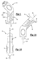
- a hand-held tool constructed in accordance with the teachings of the present invention is generally indicated by reference numeral 10.
- the tool 10 can include a housing 12, a motor assembly 14, a battery assembly 16, a circuit board 18, an overmold member 20 and a battery door 22.
- the housing 12 can be unitarily formed of a plastic material and can define a first cavity 30, a second cavity 32 and a switch aperture 34.
- the first cavity 30 has a first longitudinal axis 36 and the second cavity 32 has a second longitudinal axis 38.
- the second longitudinal axis 38 is not coincident with the first longitudinal axis 36 and intersects or is skewed to the first longitudinal axis 36 so as to define an included angle therebetween that is less than 180 degrees in magnitude.
- the housing 12 can also be configured to define a base 46, which permits the tool 10 to be stood upright thereon as is illustrated in Figure 1, and/or a scraper 48, which can be employed to scrape residue (e.g., food particles) off of a work surface, such as a dish or pan.
- residue e.g., food particles
- the motor assembly 14 can include a motor 60, a transmission 62, a gear case assembly 64 and the output member 42.
- the motor 60 can be a conventional DC motor that is adapted to be powered by the battery assembly 16.
- the motor 60 includes a pair of motor terminals 68 that can be may extend from the motor 60, as shown in Figure 11, or that can be integrated into an end cap 69 as shown in Figures 2 and 8.
- the transmission 62 which is optional, can include a gear train that can include one or more planetary gear sets 70 and a transmission output member 72.
- the ring gear (not shown) of the planetary gear sets 70 is formed on the interior of the gear case assembly 64 (i.e., on the interior of the first case member 80).
- the transmission 62 can be configured to receive a rotary input from the motor 60 and provide a rotary output to the transmission output member 72.
- the gear case assembly 64 can include a first case member 80 and a second case member 82.
- the first case member 80 can be formed in the shape of a generally hollow cylinder that is configured to receive in a press-fit manner the body 60a of the motor 60.
- the second case member 82 can be generally annular in shape and can have a case body 84, which is configured to be coupled to the first case member 80, and a case flange 86 through which an output aperture 88 can be formed.
- the case body 84 can include a seal groove 90 into which can be disposed an appropriate seal, such as an o-ring 92.
- Mounting apertures 94 can be formed through the second case member 82 in an appropriate area, such as the case flange 86.
- the mounting apertures 94 can be oriented generally parallel to one another, generally transverse to the case body 84 and offset from the output aperture 88.
- the second case member 82 When assembled to the first case member 80, the second case member 82 can cooperate with the first case member 80 to define a transmission cavity (not specifically shown) into which the transmission 62 is disposed.
- the case flange 86 can be press-fit to the first case member 80 to secure the first and second case members 80 and 82 to one another.
- Other securing means such as adhesives, welds, and/or locking tabs, for example, may additionally or alternatively be employed to secure the first and second case members 80 and 82 to one another as those of ordinary skill in the art will appreciate.
- the output member 42 can be engaged to the transmission output member 72 and can provide a means by which an accessory attachment 100, such as a brush, pad, disk or sponge, can be coupled.
- An annular seal 102 can be disposed about the transmission output member 72 which can sealingly engage the exterior face 104 of the case flange 86 as well as seal against one or both of the output member 42 and the transmission output member 72.
- the annular seal 102 can be configured to resist the infiltration of water and other liquids into the interior of the gear case assembly 64 via the output aperture 88.
- the motor assembly 14 may be received into the first cavity 30 in the housing 12 with the motor terminals 68 in a predetermined radial orientation relative to the housing 12 and the mounting apertures 94 in the gear case assembly 64 aligned to corresponding mounting apertures 108 formed in the housing 12.
- the o-ring 92 can sealingly engage the interior of the housing 12 to inhibit the infiltration of water around the gear case assembly 64 and into the interior of the housing 12.
- the first cavity 30 of the housing may be sized to receive all or portions of the gear case assembly 64 in an interference-fit manner (e.g., press fit) to inhibit relative rotation between the motor assembly 14 and the housing 12, those of ordinary skill in the art will appreciate that other mounting techniques may be additionally or alternatively employed.
- a pair of mounting pins 110 can be employed to fixedly secure the motor assembly 14 to the housing 12.
- the mounting pins 110 which can be solid pins or roll pins, can be inserted into the corresponding mounting apertures 108 and the mounting apertures 94 to engage both the housing 12 and the gear case assembly 64 to thereby inhibit movement of the motor assembly 14 relative to the housing 12 in both a radial direction and an axial direction.
- the battery assembly 16 can include a battery carrier 120, a pair of battery terminals 122 and a plurality of batteries 124.
- the batteries 124 can be any type of battery or battery cell, including rechargeable batteries, such as NiCad, nickel-metal-hydride, or lithium-ion batteries, or may be commercially-available disposable battery cells, such as alkaline battery cells.
- the battery carrier 120 can include a battery mount 130, a terminal mount 132 and a plurality of transitional terminals 134, 136 and 138.
- the battery mount 130 can define cavities 140 into which the batteries 124 may be disposed.
- the transitional terminals 134 and 136 can be coupled to an end of the battery mount 130 opposite the terminal mount 132, while the battery terminals 122 and the transitional terminal 138 can be coupled to the terminal mount 132.
- the opposite ends of the battery terminals 122 can be received into respective slots formed onto or through the terminal mount 132, while the transitional terminals 134 and 136 and the transitional terminal 138 can engage the battery carrier 120 and the terminal mount 132, respectively, in a resilient spring clip-like manner.
- the transitional terminals 134, 136 and 138 can cooperate to connect the batteries 124 in series (to create an "in-series" battery with a negative and positive terminal), while the battery terminals 122 can each be coupled to a respective one of the positive and negative terminals of the batteries (i.e., to a respective one of the negative and positive terminals of the "in-series" battery).
- the battery assembly 16 may be "keyed" to the housing 12 so as to inhibit the insertion of the battery assembly 16 in an unintended manner.
- the battery mount 130 includes a longitudinally-extending rib member 144 that is received into a corresponding groove 146 in the housing 12.
- the circuit board 18 can include a board member 150, a pair of first intermediate terminals 152, a pair of second intermediate terminals 154 and a switch 156.
- the board member 150 can include wire traces, electrical terminals and/or electrical components, such as solid-state componentry, that can be employed to control the operation of the tool 10.
- the first intermediate terminals 152 can be adapted to couple the circuit board 18 to the battery assembly 16, while the second intermediate terminals 154 can be adapted to couple the circuit board 18 to the motor assembly 14.
- the switch 156 can be mounted to the board member 150 and can be disposed between one of the first intermediate terminals 152 and an associated one of the second intermediate terminals 154 to control the distribution of electrical power from the battery assembly 16 to the motor assembly 14.
- the circuit board 18 can be installed to the housing 12 in any appropriate manner.
- the circuit board 18 can be loaded into the second cavity 32 and urged downwardly toward the intersection between the first and second cavities 30 and 32 such that the second intermediate terminals 154 electrically engage the motor terminals 68.
- the board member 150 can be abutted against a boss 160 and a threaded fastener 162 may be employed to fixedly secure the board member 150 to the boss 160.
- securing means such as adhesives, welds, and/or locking tabs, for example, may additionally or alternatively be employed to secure the board member 150 to the housing 12.
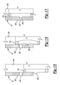
- the end cap 69 of the motor assembly 14 can include a rib 170 that is disposed proximate an associated one of the motor terminals 68.
- Each rib 170 can be arranged so as to be non-parallel to a portion of the associated motor terminal 68 such that the rib 170 and the motor terminal 68 diverge away from one another with increasing distance from the motor 60 (or alternatively stated, with decreasing distance toward the circuit board 18).
- the second intermediate terminals 154 can include a first portion 180, which can be generally parallel to the axis 38 of the second cavity 32, and a second portion 182, which can be coupled to a distal end of the first portion 180 and can extend from the first portion 180 in such a way as to define an acute included angle ⁇ therebetween. Contact between the second portion 182 of the second intermediate terminal 154 and the rib 170 can cause the second intermediate terminal 154 to act like a spring and deflect or bias the first portion 180 of the intermediate terminal 154 into contact with the associated motor terminal 68.
- the circuit board can be constructed in the manner illustrated in Figures 9 through 11.
- the second intermediate terminals 154a can include a pair of terminal members 190 that are biased toward one another and configured to receive a spade-like motor terminal 68.
- the circuit board 18a can be mounted to the housing 12 in the manner described above (i.e., fit into the second cavity 32 and mounted to a boss 160 via a threaded fastener 162) and thereafter the motor assembly 14 may be inserted into the first cavity 30 of the housing 12 such that the motor terminals 68 are received between the terminal members 190 of each of the second intermediate terminals 154a.
- the overmold member 20 which can be optional, can be an elastomeric material, such as a thermoplastic elastomer, that can be applied over the housing 12 to seal the housing 12 and/or to form a gripping area 200 on selected portions of the housing 12, such as the handle 40.
- the overmold member 20 can be employed to seal the switch aperture 34 and to form a resilient button 202 which may be employed by an operator to actuate the switch 156, as well as to optionally cover the mounting pins 110 (Fig. 2) to inhibit their removal.
- the battery door 22 can include a door structure 220 and a seal 222.
- the door structure 220 can include a body member 230, an engaging tab 232 that can extend from the body member 230, and a securing tab 234 that can extend from the body member 230 on a side opposite the engaging tab 232.
- the body member 230 can be sized to fit within the second cavity 32 and abut the battery assembly 16 to inhibit movement of the battery assembly 16 along the second longitudinal axis 38.
- the body member 230 can define a seal groove 238 into which the seal 222, which may be an o-ring, can be received.
- the seal 222 sealingly engages the interior of the housing 12 to inhibit water from traveling past the battery door 22 and into the interior of the housing 12.
- the engaging tab 232 can be sized to engage a corresponding tab aperture 240 that can be formed in the housing 12. Construction in this manner permits the user to insert the engaging tab 232 into the tab aperture 240 when securing the battery door 22 to the housing 12 so that the engaging tab 232 can be employed as a fulcrum about which the door structure 220 is pivoted.
- the securing tab 234 can be configured to overlie a portion of the housing 12 and can define an aperture 244 through which a threaded fastener 246 can be inserted.
- the threaded fastener 246 can be threadably engaged to a corresponding threaded aperture 248 in the housing 12 to fixedly but removably couple the battery door 22 to the housing 12.
- the output member 42 can have a first portion 300, which can be engaged to the transmission output member 72 (Fig. 5), and a second portion 302, which can be engaged to a drive portion 310 of an accessory 100.
- the first portion 300 includes a circular aperture 320 into which the transmission output member 72 (Fig. 5) is received.
- Any appropriate coupling means can be employed to non-rotatably couple the first portion 300 and the transmission output member 72 (Fig. 5) to one another, such as a pin 322 that can be inserted through apertures formed in the first portion 300 and the transmission output member 72 (Fig. 5) and secured in place via an interference fit with one or both of the first portion 300 and the transmission output member 72 (Fig. 5).
- the second portion 302 can include a bore 340 and one or more securing recesses 344.
- the bore 340 can be sized to receive the drive portion 310 while the securing recesses 344 can be configured to receive an associated engagement feature 350 that is formed on the drive portion 310.
- the drive portion 310 of the drive portion 310 can have a hollow interior and can be of any appropriate shape.
- the drive portion 310 is shaped in the general form of a hollow square prism having a pair of first sides 360 and a pair of second sides 362 each of which being generally transverse to and coupling the first sides 360.
- a pair of slots 366 can be formed in each of the first sides 360 in a direction that is generally parallel to a rotational axis 370 of the attachment 100.
- Each engagement feature 350 can be formed on an associated one of the first sides 360 at a location between the slots 366 and between the vertical ends of the slots 366.
- the withdrawing force exerted on the drive portion 310 drives the engagement features 350 against the output member 42 such that the first sides 360 deflect inwardly so that the engagement features 350 disengage the securing recesses 344.
- Construction of the output member 42 and the drive portion 310 of the attachment 100 in this manner provides secure coupling of the attachment 100 in a manner that permits the drive portion 310 to fail at a relatively lower torque than that which would cause the output member 42 to fail.
Priority Applications (1)
| Application Number | Priority Date | Filing Date | Title |
|---|---|---|---|
| EP08155605A EP1944854B1 (fr) | 2005-03-14 | 2005-05-24 | Scie pivotante |
Applications Claiming Priority (2)
| Application Number | Priority Date | Filing Date | Title |
|---|---|---|---|
| US11/079,518 US7414337B2 (en) | 2005-03-14 | 2005-03-14 | Scrubber |
| EP05011186A EP1703619B1 (fr) | 2005-03-14 | 2005-05-24 | Brosseuse |
Related Parent Applications (2)
| Application Number | Title | Priority Date | Filing Date |
|---|---|---|---|
| EP05011186.3 Division | 2005-05-24 | ||
| EP05011186A Division EP1703619B1 (fr) | 2005-03-14 | 2005-05-24 | Brosseuse |
Related Child Applications (2)
| Application Number | Title | Priority Date | Filing Date |
|---|---|---|---|
| EP08155605A Division EP1944854B1 (fr) | 2005-03-14 | 2005-05-24 | Scie pivotante |
| EP08155605.2 Division-Into | 2008-05-02 |
Publications (4)
| Publication Number | Publication Date |
|---|---|
| EP1850462A2 true EP1850462A2 (fr) | 2007-10-31 |
| EP1850462A3 EP1850462A3 (fr) | 2007-11-14 |
| EP1850462B1 EP1850462B1 (fr) | 2008-12-24 |
| EP1850462B8 EP1850462B8 (fr) | 2010-09-15 |
Family
ID=36430906
Family Applications (3)
| Application Number | Title | Priority Date | Filing Date |
|---|---|---|---|
| EP07114395A Not-in-force EP1850462B8 (fr) | 2005-03-14 | 2005-05-24 | Épurateur |
| EP05011186A Not-in-force EP1703619B1 (fr) | 2005-03-14 | 2005-05-24 | Brosseuse |
| EP08155605A Not-in-force EP1944854B1 (fr) | 2005-03-14 | 2005-05-24 | Scie pivotante |
Family Applications After (2)
| Application Number | Title | Priority Date | Filing Date |
|---|---|---|---|
| EP05011186A Not-in-force EP1703619B1 (fr) | 2005-03-14 | 2005-05-24 | Brosseuse |
| EP08155605A Not-in-force EP1944854B1 (fr) | 2005-03-14 | 2005-05-24 | Scie pivotante |
Country Status (7)
| Country | Link |
|---|---|
| US (2) | US7414337B2 (fr) |
| EP (3) | EP1850462B8 (fr) |
| CN (1) | CN1833825B (fr) |
| AT (3) | ATE405024T1 (fr) |
| AU (1) | AU2005234679A1 (fr) |
| DE (3) | DE602005008900D1 (fr) |
| ES (1) | ES2313151T3 (fr) |
Cited By (1)
| Publication number | Priority date | Publication date | Assignee | Title |
|---|---|---|---|---|
| US7818864B2 (en) * | 2005-03-14 | 2010-10-26 | Black & Decker Inc. | Scrubber |
Families Citing this family (52)
| Publication number | Priority date | Publication date | Assignee | Title |
|---|---|---|---|---|
| EP2062334A1 (fr) * | 2006-09-11 | 2009-05-27 | Cembre S.p.A. | Outil de presse et/ou de découpe hydraulique et mécanisme de conversion d'un mouvement rotatif en mouvement oscillant en translation pour cet outil |
| FR2938413B1 (fr) * | 2008-11-17 | 2012-03-16 | Somfy Sas | Actionneur de manoeuvre d'un rideau coulissant |
| US10258442B2 (en) | 2009-03-20 | 2019-04-16 | Water Pik, Inc. | Oral irrigator appliance with radiant energy delivery for bactericidal effect |
| WO2010121941A2 (fr) * | 2009-04-20 | 2010-10-28 | Aesculap Suhl Gmbh | Tondeuse pour animaux |
| JP5461221B2 (ja) | 2010-02-12 | 2014-04-02 | 株式会社マキタ | 複数のバッテリパックを電源とする電動工具 |
| CH703098A2 (de) | 2010-05-03 | 2011-11-15 | Peter A Mueller | Koppelbarer Antrieb. |
| JP2012035398A (ja) | 2010-08-11 | 2012-02-23 | Makita Corp | 複数の単セルバッテリパックを有する電動工具 |
| USD706786S1 (en) * | 2011-06-13 | 2014-06-10 | TecDriven, LLC | Handle for an electronic device |
| US9179583B2 (en) | 2011-09-27 | 2015-11-03 | Johnson & Johnson Consumer Companies, Inc. | Water resistant electromechanical personal body-care device |
| US8887345B2 (en) * | 2012-02-03 | 2014-11-18 | Mark Gonzalez | Cadet |
| JP5942580B2 (ja) * | 2012-05-15 | 2016-06-29 | マックス株式会社 | 電動工具 |
| CN205609608U (zh) | 2012-06-12 | 2016-09-28 | 米沃奇电动工具公司 | 电池组 |
| US9642677B2 (en) | 2013-03-14 | 2017-05-09 | Water Pik, Inc. | Oral irrigator with massage mode |
| DE102013215821A1 (de) * | 2013-08-09 | 2015-02-12 | Robert Bosch Gmbh | Handwerkzeugmaschine mit einem elektromotorischen Antrieb als Direktantrieb |
| ES2718685T3 (es) | 2013-11-27 | 2019-07-03 | Water Pik Inc | Irrigador bucal con interruptor de pausa deslizante |
| US9980793B2 (en) | 2013-11-27 | 2018-05-29 | Water Pik, Inc. | Oral hygiene system |
| CN203693808U (zh) * | 2013-12-12 | 2014-07-09 | 洁碧有限公司 | 牙科用喷水器 |
| US9954418B2 (en) | 2014-03-17 | 2018-04-24 | Makita Corporation | Power tool |
| CN205586102U (zh) | 2014-12-01 | 2016-09-21 | 洁碧有限公司 | 防水无线口腔冲洗器 |
| KR102072661B1 (ko) | 2016-01-25 | 2020-02-03 | 워터 피크 인코포레이티드 | 형상 인자가 감소된 구강 세정기 |
| USD809650S1 (en) | 2016-02-22 | 2018-02-06 | Water Pik, Inc. | Oral irrigator |
| DE102016003150A1 (de) * | 2016-03-16 | 2017-09-21 | Andreas Stihl Ag & Co. Kg | Handgeführtes Arbeitsgerät mit einem Elektromotor |
| USD800251S1 (en) | 2016-09-28 | 2017-10-17 | E. Mishan & Sons, Inc. | Rotary scrubber |
| USD829886S1 (en) | 2016-12-15 | 2018-10-02 | Water Pik, Inc. | Oral irrigator base |
| USD832419S1 (en) | 2016-12-15 | 2018-10-30 | Water Pik, Inc. | Oral irrigator unit |
| USD840023S1 (en) | 2016-12-15 | 2019-02-05 | Water Pik, Inc. | Oral irrigator reservoir |
| USD839409S1 (en) | 2016-12-15 | 2019-01-29 | Water Pik, Inc. | Oral irrigator unit |
| CN114642510A (zh) | 2016-12-15 | 2022-06-21 | 洁碧有限公司 | 用于口腔冲洗器手柄的暂停阀和绕转组件 |
| USD832418S1 (en) | 2016-12-15 | 2018-10-30 | Water Pik, Inc. | Oral irrigator base |
| USD832420S1 (en) | 2016-12-15 | 2018-10-30 | Water Pik, Inc. | Oral irrigator base |
| USD834180S1 (en) | 2016-12-15 | 2018-11-20 | Water Pik, Inc. | Oral irrigator base |
| USD867579S1 (en) | 2016-12-15 | 2019-11-19 | Water Pik, Inc. | Oral irrigator unit |
| WO2018112387A1 (fr) | 2016-12-15 | 2018-06-21 | Water Pik, Inc. | Irrigateur buccal à fixation magnétique |
| USD833000S1 (en) | 2016-12-15 | 2018-11-06 | Water Pik, Inc. | Oral irrigator unit |
| USD825741S1 (en) | 2016-12-15 | 2018-08-14 | Water Pik, Inc. | Oral irrigator handle |
| USD833600S1 (en) | 2016-12-15 | 2018-11-13 | Water Pik, Inc. | Oral irrigator reservoir |
| USD833602S1 (en) | 2017-02-06 | 2018-11-13 | Water Pik, Inc. | Oral irrigator base |
| USD829887S1 (en) | 2017-02-06 | 2018-10-02 | Water Pik, Inc. | Oral irrigator reservoir |
| USD833601S1 (en) | 2017-02-06 | 2018-11-13 | Water Pik, Inc. | Oral irrigator |
| US11431224B2 (en) * | 2017-02-15 | 2022-08-30 | Black & Decker Inc. | Power and home tools |
| CN107095726B (zh) * | 2017-04-25 | 2023-06-02 | 深圳市云顶信息技术有限公司 | 电动牙刷 |
| US10840776B2 (en) | 2017-05-27 | 2020-11-17 | Actuator Electric Motors | Self-contained brushless motor and brushless controller |
| USD849494S1 (en) | 2017-08-17 | 2019-05-28 | E. Mishan & Sons, Inc. | Handheld scrubber |
| JP2017226072A (ja) * | 2017-10-03 | 2017-12-28 | 株式会社マキタ | 電動工具 |
| USD868243S1 (en) | 2018-03-16 | 2019-11-26 | Water Pik, Inc. | Oral irrigator tip |
| USD877324S1 (en) | 2018-05-17 | 2020-03-03 | Water Pik, Inc. | Oral irrigator handle |
| IT201800007471A1 (it) * | 2018-07-24 | 2020-01-24 | Pompa idraulica per un utensile idrodinamico di compressione | |
| JP7210261B2 (ja) | 2018-12-14 | 2023-01-23 | 株式会社マキタ | 電動作業機及び電動作業機用モータにおけるステータの製造方法 |
| TWM580028U (zh) * | 2019-01-23 | 2019-07-01 | 益航電子股份有限公司 | 手持式工具機 |
| USD923270S1 (en) | 2019-08-27 | 2021-06-22 | E. Mishan & Sons, Inc. | Scrubber |
| US11565394B2 (en) | 2019-10-28 | 2023-01-31 | Snap-On Incorporated | Double reduction gear train |
| EP3866312A1 (fr) * | 2020-02-14 | 2021-08-18 | Andreas Stihl AG & Co. KG | Appareil de traitement guidé à la main et procédé de fabrication d'un appareil de traitement guidé à la main |
Citations (5)
| Publication number | Priority date | Publication date | Assignee | Title |
|---|---|---|---|---|
| US5697115A (en) | 1996-04-29 | 1997-12-16 | Black & Decker Inc. | Cleaning apparatus with triangular shaped mount for attachment and quick disconnect |
| US5718014A (en) | 1996-04-29 | 1998-02-17 | Black & Decker Inc. | Hand held motorized tool with over-molded cover |
| US5956792A (en) | 1996-04-29 | 1999-09-28 | Black & Decker, Inc. | Hand held motorized cleaning apparatus with linear, orbital and/or dual motion |
| US5978999A (en) | 1996-04-29 | 1999-11-09 | Black & Decker Inc. | Motorized scrub brush with multiple hand holding positions |
| US20040112616A1 (en) | 2001-03-24 | 2004-06-17 | Peter Broghammer | Control device for an electric motor |
Family Cites Families (131)
| Publication number | Priority date | Publication date | Assignee | Title |
|---|---|---|---|---|
| DE32872C (de) | GEBR. FRANKE in Chemnitz | Ausrücke-Vorrichtung für Spul- und Zwirn - Maschinen | ||
| DE7431959U (de) | 1975-03-13 | Roth H | Druckspritze | |
| US1198799A (en) * | 1915-11-15 | 1916-09-19 | Wilmer W Westrup | Massaging implement. |
| US2357291A (en) * | 1939-05-05 | 1944-09-05 | Arthur G Smith | Surface conditioner |
| US2772430A (en) | 1953-07-13 | 1956-12-04 | Irving J Moritt | Dish cleaning device with detergent feed |
| US2993220A (en) * | 1959-12-07 | 1961-07-25 | Rufus S Nix | Toothbrush and gum massager |
| US3024487A (en) | 1960-04-25 | 1962-03-13 | Reginald H Jones | Multipurpose scrubber |
| CH365051A (fr) | 1960-10-27 | 1962-10-31 | P Perrinjaquet Roger | Appareil électrique pour le brossage des dents |
| US3293678A (en) | 1964-10-19 | 1966-12-27 | Howard D South | Power-driven hand-held polishing and cleaning device |
| US3358309A (en) | 1965-12-27 | 1967-12-19 | Empire Brushes Inc | Cordless electric vibrating hair brush, or like vibrating manipulators |
| US3343192A (en) | 1966-01-28 | 1967-09-26 | Goldstein Morton | Power operated cleaning device |
| US3396417A (en) | 1966-09-12 | 1968-08-13 | Richard A. Starr | Window washer |
| US3443272A (en) | 1967-09-01 | 1969-05-13 | Mc Graw Edison Co | Upholstery cleaner |
| DE6607845U (de) | 1967-11-02 | 1971-05-13 | Bremshey & Co | Vorzugsweise als haushalt-handgeraet ausgebildeter antriebsmotor. |
| US3447178A (en) | 1968-01-26 | 1969-06-03 | John J Pickering | Electric toothbrush |
| DE1921071A1 (de) | 1969-04-25 | 1970-11-12 | Hauni Werke Koerber & Co Kg | Antriebseinheit fuer rotierende Werkzeuge,vorzugsweise eine Schuhbuerste |
| US3577675A (en) | 1969-07-15 | 1971-05-04 | Kohner Bros Inc | Child{3 s bathing toy |
| US3892004A (en) | 1972-10-06 | 1975-07-01 | Thomas Downes | Domestic cleaning apparatus |
| US4129257A (en) | 1973-10-23 | 1978-12-12 | Uwe Eggert | Jet mouth piece |
| US3977084A (en) | 1974-08-26 | 1976-08-31 | Tsset Scientific And Pharmaceutical Limited | Dental hygienic device |
| US4060870A (en) | 1975-12-23 | 1977-12-06 | Anthony Cannarella | Toothpaste administering automatic toothbrush |
| US4027348A (en) * | 1976-01-12 | 1977-06-07 | Sperry Rand Corporation | Skin treatment appliance |
| US4168650A (en) | 1976-06-25 | 1979-09-25 | Sps Technologies, Inc. | Blind fastener |
| US4213471A (en) | 1978-05-15 | 1980-07-22 | Clairol, Inc | Manicuring unit |
| US4168560A (en) | 1978-10-12 | 1979-09-25 | Doyel John S | Battery-driven cleaning device |
| US4241297A (en) * | 1978-11-20 | 1980-12-23 | Eaton Corporation | Double-pole trigger speed control switch |
| USD262670S (en) | 1979-01-25 | 1982-01-19 | U.S. Industrial Tool & Supply Co. | Air powered rotary scrubbing brush |
| EP0046521A1 (fr) | 1980-08-25 | 1982-03-03 | Giosuè Mario Lazzari | Dispositif motorisé rotatif pour le nettoyage des dents |
| US4409755A (en) | 1981-03-05 | 1983-10-18 | Maddock Mitchell E | Hand held liquid herbicide applicator |
| DE3147769A1 (de) | 1981-12-02 | 1983-06-16 | Bosch-Siemens Hausgeräte GmbH, 7000 Stuttgart | Absperrventil fuer unter druck stehende karbonisierte fluessigkeiten in getraenkeautomaten o.dgl. |
| DE3244262A1 (de) * | 1982-11-30 | 1984-05-30 | Blendax-Werke R. Schneider Gmbh & Co, 6500 Mainz | Elektrisch angetriebene zahnbuerste |
| JPS5992630U (ja) * | 1982-12-16 | 1984-06-23 | 株式会社共立 | 刈払機 |
| DE8332941U1 (de) | 1983-11-17 | 1984-02-16 | Miller, Franz Georg, 7250 Leonberg | Reinigungsvorrichtung |
| US4556803A (en) * | 1984-02-29 | 1985-12-03 | Electro-Matic Staplers, Inc. | Trigger switch circuit for solenoid-actuated electric hand tool |
| US4552476A (en) | 1984-03-08 | 1985-11-12 | Heraty Patrick T | Combination high pressure wand and brush for vehicle washing |
| JPS6131433U (ja) | 1984-07-30 | 1986-02-25 | 市川プレス工業株式会社 | 携帯用あんま器 |
| DE3510107C2 (de) | 1985-03-20 | 1996-01-04 | Dieter Kuhn | Mundstück eines Dusch- oder Brausekopfes |
| USD301398S (en) | 1985-09-30 | 1989-06-06 | Cheung Henry C H | Shoe polishing set |
| EP0241557B1 (fr) | 1985-10-15 | 1992-02-26 | Pan American Trading Co.,Ltd. | Injecteur de ciment liquide |
| DE3615918A1 (de) | 1986-05-12 | 1987-11-19 | Eckart Mayer | Manuell handhabbare reinigungsvorrichtung |
| US4930664A (en) | 1987-01-15 | 1990-06-05 | Root-Lowell Manufacturing Company | Self-pressurizing sprayer |
| US4782982A (en) | 1987-01-15 | 1988-11-08 | Root-Lowell Manufacturing Company | Self-pressurizing sprayer |
| EP0280527A3 (fr) * | 1987-02-24 | 1990-06-13 | Yang Tai-Her | Outil électrique à main à éléments composables |
| USD313890S (en) | 1987-04-17 | 1991-01-22 | Machuron Robert M | Electric scrubbing brush |
| KR890008121Y1 (en) | 1987-05-13 | 1989-11-20 | Shin Byong Gwon | Glass cleaners |
| DE8710130U1 (fr) | 1987-07-21 | 1988-05-19 | Anthos Vermoegensverwaltungs Gmbh, 1000 Berlin, De | |
| US4835410A (en) * | 1988-02-26 | 1989-05-30 | Black & Decker Inc. | Dual-mode corded/cordless system for power-operated devices |
| JP2944095B2 (ja) * | 1988-03-11 | 1999-08-30 | ブラック アンド デッカー インコーポレイティド | 電池式工具の電池ケース及び充電器 |
| US4964398A (en) | 1988-04-18 | 1990-10-23 | Jones Letha L | Shampoo or massage device |
| ES1004996Y (es) | 1988-04-20 | 1989-04-01 | Misitu Ochoa Juan Antonio | Cepillo perfeccionado para limpieza de tapizados |
| USD311278S (en) | 1988-06-02 | 1990-10-16 | Swanson Robert A | Water driven rotary brush for washing wire wheels or similar articles |
| US4932094A (en) | 1988-12-22 | 1990-06-12 | The Boeing Company | Liquid applicator tool |
| DE59008112D1 (de) * | 1989-07-15 | 1995-02-09 | Kress Elektrik Gmbh & Co | Elektrowerkzeug. |
| DE9100264U1 (fr) | 1991-01-11 | 1991-04-11 | Eisenhauer, Josef, Dipl.-Ing. (Fh), 6987 Kuelsheim, De | |
| WO1992019389A1 (fr) | 1991-04-26 | 1992-11-12 | Toppan Printing Co., Ltd. | Distributeur de matiere visqueuse |
| US5207697A (en) * | 1991-06-27 | 1993-05-04 | Stryker Corporation | Battery powered surgical handpiece |
| US5289605A (en) | 1991-12-10 | 1994-03-01 | Armbruster Joseph M | DC powered scrubber |
| EP0550818B1 (fr) | 1992-01-09 | 1998-03-18 | Breitschmid AG | Manche avec moyen de fixation et brosse interdentale s'y attachant de façon amovible |
| JPH05329024A (ja) * | 1992-05-29 | 1993-12-14 | Nippon Philips Kk | 電動歯ブラシ |
| DE4226928A1 (de) | 1992-08-17 | 1994-02-24 | Grobbel Michael Dipl Designer | Außenmischendes Spritzgerät mit umfassender Beeinflussung des Spritzbildes während des Spritzens |
| DE4234764C2 (de) | 1992-10-15 | 1994-08-18 | Jovica Vukosavljevic | Einrastverbindung für eine teilbare Bürste, insbesondere Zahnbürste |
| DE9215222U1 (fr) | 1992-11-09 | 1992-12-24 | Gassner, Wolfgang, Dr.-Ing., 8025 Unterhaching, De | |
| US5301381A (en) | 1992-12-07 | 1994-04-12 | Klupt Michael F | Toothbrush system |
| US5632416A (en) | 1993-01-29 | 1997-05-27 | W. A. Lane, Inc. | Collapsible dispenser pouch |
| US5363723A (en) * | 1993-02-23 | 1994-11-15 | Ryobi Outdoor Products, Inc. | Angle gear drive |
| DE4315320B4 (de) * | 1993-05-08 | 2004-05-06 | Muti, Arturo, Dr. | Zylindrische Bürste mit motorischem Antrieb zur Körperraumbehandlung |
| US5353461A (en) | 1993-09-20 | 1994-10-11 | Kevin Enriquez | Rotary scrubber apparatus |
| DE4335075C2 (de) | 1993-10-14 | 1995-09-07 | Rudolf Joos | Reinigungsvorrichtung, insbesondere für Tierhufe |
| DE4335445A1 (de) | 1993-10-18 | 1995-04-20 | Marlene Roubert | Haushalts-Akku-Scheurer |
| US5458159A (en) * | 1993-12-17 | 1995-10-17 | Cooper Industries, Inc. | Shielded electrically powered wire wrap tool |
| US5450646A (en) * | 1994-07-25 | 1995-09-19 | Mchugh; Hugh M. | Pot washer |
| US5423102A (en) | 1994-08-19 | 1995-06-13 | Madison; Ava | Portable cleaning device |
| US5471695A (en) * | 1994-08-31 | 1995-12-05 | Aiyar; Sanjay | Motorized brush |
| US5500972A (en) | 1994-11-07 | 1996-03-26 | Foster; David C. | Rotating back scrubber |
| EP0836534B1 (fr) | 1995-05-05 | 2002-09-18 | Essex Specialty Products, Inc. | Procede et pistolet de distribution de matieres, a commande electrique |
| US5701625A (en) | 1995-07-18 | 1997-12-30 | Siman; Walid | Scrub cleaning machine |
| US5738177A (en) * | 1995-07-28 | 1998-04-14 | Black & Decker Inc. | Production assembly tool |
| US5664634A (en) * | 1995-10-23 | 1997-09-09 | Waxing Corporation Of America, Inc. | Power tool |
| USD413445S (en) | 1996-01-16 | 1999-09-07 | Black & Decker Inc. | Scrub brush handle |
| US5735620A (en) | 1996-03-11 | 1998-04-07 | Ford; Peggy D. | Multi-purpose cleaning tool |
| US5747953A (en) * | 1996-03-29 | 1998-05-05 | Stryker Corporation | Cordless, battery operated surical tool |
| US5870790A (en) | 1996-08-02 | 1999-02-16 | Root; Jeffrey T. | Powered water submersible scrubbing device |
| US5680666A (en) | 1996-10-15 | 1997-10-28 | Ra; Dojin | Automatic polishing device |
| DE19651371A1 (de) | 1996-12-11 | 1998-06-18 | Weber Franz Josef | Bürste, insbesondere zum Reinigen von Toilettenbecken |
| US5784744A (en) | 1997-01-09 | 1998-07-28 | Toran; Steven | Portable shampoo device |
| FR2762531B1 (fr) | 1997-04-28 | 1999-08-13 | Superba Sa | Appareil portable omnidirectionnel de nettoyage a la vapeur de surfaces dures ou souples |
| JPH1122816A (ja) * | 1997-06-30 | 1999-01-26 | Aisin Seiki Co Ltd | シンクロメッシュ式トランスミッションの変速制御装置 |
| US6078117A (en) * | 1997-08-27 | 2000-06-20 | Nartron Corporation | End cap assembly and electrical motor utilizing same |
| NL1007168C2 (nl) | 1997-09-30 | 1999-03-31 | Sara Lee De Nv | Pomp en uitlaatmondstuk van pomp. |
| US5960503A (en) | 1997-12-02 | 1999-10-05 | Del Pozo Y Mattei; Gilberto R. | Kitchen utensil cleaning tool |
| US6134738A (en) | 1998-05-27 | 2000-10-24 | Bintraco Gmbh | Brush construction for cleaning toilet bowls |
| TW389684B (en) | 1998-08-20 | 2000-05-11 | Luo De Liang | Portable electric cleaning device |
| US6371294B1 (en) * | 1998-09-30 | 2002-04-16 | The Procter & Gamble Company | Electric toothbrush |
| EP0990402A3 (fr) | 1998-09-30 | 2003-09-24 | Tek Maker Corporation | Appareil électrique portatif de nettoyage |
| US6178579B1 (en) * | 1998-09-30 | 2001-01-30 | Dr. Johns Products, Ltd. | Electric toothbrush |
| US6000083A (en) * | 1998-09-30 | 1999-12-14 | Dr. Johns Products, Ltd. | Electric toothbrush |
| US6292971B1 (en) | 1998-12-07 | 2001-09-25 | Muhammad I. Chaudray | Power cleaning brush |
| US6477919B1 (en) * | 1999-02-02 | 2002-11-12 | Chromatography Research Supplies, Inc. | Powered decapping tool to remove a cap from a bottle or vial |
| US6076330A (en) * | 1999-02-02 | 2000-06-20 | Thomas; Glenn E. | Powered crimping tool to secure a cap onto a bottle or vial |
| US6683396B2 (en) * | 1999-07-02 | 2004-01-27 | Matsushita Electric Works, Ltd. | Portable motor powered device |
| JP3349118B2 (ja) | 1999-07-23 | 2002-11-20 | 日本電産コパル株式会社 | モータ及び携帯電話 |
| US6196045B1 (en) * | 1999-12-20 | 2001-03-06 | Chromatography Research Supplies, Inc. | Powered crimping tool |
| US6425701B1 (en) | 2000-02-23 | 2002-07-30 | Rubbermaid Incorporated | Liquid dispensing handle |
| GB0005821D0 (en) * | 2000-03-10 | 2000-05-03 | Black & Decker Inc | Coupling method |
| US6511336B1 (en) | 2000-05-25 | 2003-01-28 | Illinois Tool Works Inc. | Solderless flex termination for motor tab |
| GB0014495D0 (en) | 2000-06-15 | 2000-08-09 | Smithkline Beecham Gmbh & Co | Process |
| EP1304989B1 (fr) | 2000-07-13 | 2005-10-12 | Koninklijke Philips Electronics N.V. | Dispositif destine au traitement d'une region du corps humain, et en particulier du visage |
| US6752330B2 (en) | 2000-07-24 | 2004-06-22 | The Procter & Gamble Company | Liquid sprayers |
| US6502766B1 (en) | 2000-07-24 | 2003-01-07 | The Procter & Gamble Company | Liquid sprayers |
| DE20015053U1 (de) | 2000-08-31 | 2000-10-26 | 2 Mad Gmbh I G | Tragbares Schuhputzgerät |
| AU2002239480B2 (en) | 2000-10-23 | 2005-06-02 | Medical Instill Technologies, Inc. | Fluid dispenser with bladder inside rigid vial |
| US6554614B1 (en) | 2001-05-03 | 2003-04-29 | 3M Innovative Properties Company | Dental handpiece brush and method of using the same |
| US6792640B2 (en) * | 2001-06-29 | 2004-09-21 | Homedics, Inc. | Automatic electric toothbrush |
| US6952855B2 (en) * | 2001-06-29 | 2005-10-11 | Homedics, Inc. | Automatic electric toothbrush |
| EP1302283A2 (fr) * | 2001-10-09 | 2003-04-16 | B&Q Plc | Outil à main motorisé |
| KR20020003537A (ko) * | 2001-11-27 | 2002-01-12 | 박찬석 | 개인 휴대용 자동 때밀이 장치 |
| US6954961B2 (en) * | 2002-05-03 | 2005-10-18 | Homedics, Inc. | Light emitting toothbrush |
| ATE326894T1 (de) | 2002-05-21 | 2006-06-15 | Koninkl Philips Electronics Nv | Gerät zum behandeln der haut eines menschen |
| US6859968B2 (en) * | 2002-06-24 | 2005-03-01 | Koninklijke Philips Electronics N.V. | Nodal mounted system for driving a power appliance |
| DE20214940U1 (de) | 2002-09-26 | 2004-02-19 | Hako-Werke Gmbh | Vorrichtung zur Befestigung und/oder zum Antreiben eines Bürstenkörpers |
| CA102737S (en) | 2002-10-10 | 2004-12-29 | Reckitt Benckiser Inc | Brush |
| US20040074025A1 (en) | 2002-10-17 | 2004-04-22 | Blaustein Lawrence A. | Hand-held, battery powered cleaning tool with stand |
| USD515818S1 (en) | 2002-12-13 | 2006-02-28 | Groblebe David G | Manual dishwashing spray head with interchangeable brushes |
| AU154021S (en) | 2003-04-03 | 2003-12-12 | Reckitt Benckiser Inc | Brush |
| JP4178077B2 (ja) | 2003-06-04 | 2008-11-12 | 日東電工株式会社 | 配線回路基板 |
| TWI229490B (en) | 2003-06-20 | 2005-03-11 | Ren-Tang Jang | Structure of power supply for external tool |
| AU155974S (en) | 2003-07-18 | 2004-07-20 | Reckitt Benckiser Inc | Cleaning brush |
| DE20321117U1 (de) * | 2003-09-29 | 2005-12-22 | Robert Bosch Gmbh | Akkuschrauber |
| JP2005144564A (ja) * | 2003-11-11 | 2005-06-09 | Matsushita Electric Works Ltd | 可搬式電動工具 |
| US7044674B2 (en) | 2004-10-01 | 2006-05-16 | Dixon Marcia A | Multi purpose hand held cleaning device |
| US7414337B2 (en) * | 2005-03-14 | 2008-08-19 | Black & Decker Inc. | Scrubber |
-
2005
- 2005-03-14 US US11/079,518 patent/US7414337B2/en not_active Expired - Fee Related
- 2005-05-24 DE DE602005008900T patent/DE602005008900D1/de active Active
- 2005-05-24 EP EP07114395A patent/EP1850462B8/fr not_active Not-in-force
- 2005-05-24 AT AT05011186T patent/ATE405024T1/de not_active IP Right Cessation
- 2005-05-24 AT AT08155605T patent/ATE451749T1/de not_active IP Right Cessation
- 2005-05-24 DE DE602005018275T patent/DE602005018275D1/de active Active
- 2005-05-24 EP EP05011186A patent/EP1703619B1/fr not_active Not-in-force
- 2005-05-24 ES ES05011186T patent/ES2313151T3/es active Active
- 2005-05-24 AT AT07114395T patent/ATE418811T1/de not_active IP Right Cessation
- 2005-05-24 EP EP08155605A patent/EP1944854B1/fr not_active Not-in-force
- 2005-05-24 DE DE602005011996T patent/DE602005011996D1/de active Active
- 2005-06-27 CN CN200510081000.XA patent/CN1833825B/zh not_active Expired - Fee Related
- 2005-11-18 AU AU2005234679A patent/AU2005234679A1/en not_active Abandoned
-
2008
- 2008-05-06 US US12/115,990 patent/US7818864B2/en not_active Expired - Fee Related
Patent Citations (7)
| Publication number | Priority date | Publication date | Assignee | Title |
|---|---|---|---|---|
| US5697115A (en) | 1996-04-29 | 1997-12-16 | Black & Decker Inc. | Cleaning apparatus with triangular shaped mount for attachment and quick disconnect |
| US5718014A (en) | 1996-04-29 | 1998-02-17 | Black & Decker Inc. | Hand held motorized tool with over-molded cover |
| US5956792A (en) | 1996-04-29 | 1999-09-28 | Black & Decker, Inc. | Hand held motorized cleaning apparatus with linear, orbital and/or dual motion |
| US5978999A (en) | 1996-04-29 | 1999-11-09 | Black & Decker Inc. | Motorized scrub brush with multiple hand holding positions |
| US6248007B1 (en) | 1996-04-29 | 2001-06-19 | Black & Decker, Inc. | Hand held motorized tool with over-molded cover |
| US6253405B1 (en) | 1996-04-29 | 2001-07-03 | Black & Decker, Inc. | Hand held motorized cleaning apparatus with linear, orbital and/or dual motion |
| US20040112616A1 (en) | 2001-03-24 | 2004-06-17 | Peter Broghammer | Control device for an electric motor |
Cited By (1)
| Publication number | Priority date | Publication date | Assignee | Title |
|---|---|---|---|---|
| US7818864B2 (en) * | 2005-03-14 | 2010-10-26 | Black & Decker Inc. | Scrubber |
Also Published As
| Publication number | Publication date |
|---|---|
| US7414337B2 (en) | 2008-08-19 |
| EP1703619A1 (fr) | 2006-09-20 |
| EP1944854A3 (fr) | 2008-07-23 |
| DE602005018275D1 (de) | 2010-01-21 |
| EP1703619B1 (fr) | 2008-08-13 |
| AU2005234679A1 (en) | 2006-09-28 |
| DE602005011996D1 (de) | 2009-02-05 |
| ATE418811T1 (de) | 2009-01-15 |
| US7818864B2 (en) | 2010-10-26 |
| ATE405024T1 (de) | 2008-08-15 |
| EP1944854A2 (fr) | 2008-07-16 |
| EP1850462B8 (fr) | 2010-09-15 |
| CN1833825A (zh) | 2006-09-20 |
| EP1850462A3 (fr) | 2007-11-14 |
| US20060202571A1 (en) | 2006-09-14 |
| CN1833825B (zh) | 2014-02-26 |
| ATE451749T1 (de) | 2009-12-15 |
| ES2313151T3 (es) | 2009-03-01 |
| DE602005008900D1 (de) | 2008-09-25 |
| EP1850462B1 (fr) | 2008-12-24 |
| US20080222871A1 (en) | 2008-09-18 |
| EP1944854B1 (fr) | 2009-12-09 |
Similar Documents
| Publication | Publication Date | Title |
|---|---|---|
| EP1703619B1 (fr) | Brosseuse | |
| AU2003213500B2 (en) | Power tool with integral gripping member | |
| US7456608B2 (en) | Battery-driven screwdriver | |
| US8999542B2 (en) | Electric tools | |
| US7546785B2 (en) | Battery-operated screwdriver | |
| EP1913858B1 (fr) | Balai-brosse | |
| US20060219059A1 (en) | Battery-driven screwdriver with a two-part motor housing and a separate, flanged gear unit | |
| US7322500B2 (en) | Hand tool for motor vehicle | |
| US20060119318A1 (en) | Power tools, battery chargers and batteries | |
| US11351667B2 (en) | Tool basic module | |
| MX2014000489A (es) | Herramienta con cabezal giratorio. | |
| US20030200841A1 (en) | Articulation lock and pivotable tool using same | |
| US20100325892A1 (en) | Razor | |
| CN108367425B (zh) | 手持式工具机 | |
| CN213184464U (zh) | 电池组和电动工具 | |
| EP3772394B1 (fr) | Bloc-batterie | |
| CN112106222A (zh) | 蓄电池包 | |
| KR200175428Y1 (ko) | 전동 때밀이용구 |
Legal Events
| Date | Code | Title | Description |
|---|---|---|---|
| PUAI | Public reference made under article 153(3) epc to a published international application that has entered the european phase |
Free format text: ORIGINAL CODE: 0009012 |
|
| PUAL | Search report despatched |
Free format text: ORIGINAL CODE: 0009013 |
|
| 17P | Request for examination filed |
Effective date: 20070815 |
|
| AC | Divisional application: reference to earlier application |
Ref document number: 1703619 Country of ref document: EP Kind code of ref document: P |
|
| AK | Designated contracting states |
Kind code of ref document: A2 Designated state(s): AT BE BG CH CY CZ DE DK EE ES FI FR GB GR HU IE IS IT LI LT LU LV MC MT NL PL PT RO SE SI SK TR |
|
| AX | Request for extension of the european patent |
Extension state: AL BA HR MK YU |
|
| AK | Designated contracting states |
Kind code of ref document: A3 Designated state(s): AT BE BG CH CY CZ DE DK EE ES FI FR GB GR HU IE IS IT LI LT LU LV MC MT NL PL PT RO SE SI SK TR |
|
| AX | Request for extension of the european patent |
Extension state: AL BA HR MK YU |
|
| 17Q | First examination report despatched |
Effective date: 20080207 |
|
| GRAP | Despatch of communication of intention to grant a patent |
Free format text: ORIGINAL CODE: EPIDOSNIGR1 |
|
| AKX | Designation fees paid |
Designated state(s): AT BE BG CH CY CZ DE DK EE ES FI FR GB GR HU IE IS IT LI LT LU LV MC MT NL PL PT RO SE SI SK TR |
|
| GRAS | Grant fee paid |
Free format text: ORIGINAL CODE: EPIDOSNIGR3 |
|
| GRAA | (expected) grant |
Free format text: ORIGINAL CODE: 0009210 |
|
| AC | Divisional application: reference to earlier application |
Ref document number: 1703619 Country of ref document: EP Kind code of ref document: P |
|
| AK | Designated contracting states |
Kind code of ref document: B1 Designated state(s): AT BE BG CH CY CZ DE DK EE ES FI FR GB GR HU IE IS IT LI LT LU LV MC MT NL PL PT RO SE SI SK TR |
|
| REG | Reference to a national code |
Ref country code: GB Ref legal event code: FG4D |
|
| REG | Reference to a national code |
Ref country code: CH Ref legal event code: EP |
|
| REG | Reference to a national code |
Ref country code: IE Ref legal event code: FG4D |
|
| REF | Corresponds to: |
Ref document number: 602005011996 Country of ref document: DE Date of ref document: 20090205 Kind code of ref document: P |
|
| PG25 | Lapsed in a contracting state [announced via postgrant information from national office to epo] |
Ref country code: LT Free format text: LAPSE BECAUSE OF FAILURE TO SUBMIT A TRANSLATION OF THE DESCRIPTION OR TO PAY THE FEE WITHIN THE PRESCRIBED TIME-LIMIT Effective date: 20081224 |
|
| PG25 | Lapsed in a contracting state [announced via postgrant information from national office to epo] |
Ref country code: LV Free format text: LAPSE BECAUSE OF FAILURE TO SUBMIT A TRANSLATION OF THE DESCRIPTION OR TO PAY THE FEE WITHIN THE PRESCRIBED TIME-LIMIT Effective date: 20081224 Ref country code: SI Free format text: LAPSE BECAUSE OF FAILURE TO SUBMIT A TRANSLATION OF THE DESCRIPTION OR TO PAY THE FEE WITHIN THE PRESCRIBED TIME-LIMIT Effective date: 20081224 Ref country code: PL Free format text: LAPSE BECAUSE OF FAILURE TO SUBMIT A TRANSLATION OF THE DESCRIPTION OR TO PAY THE FEE WITHIN THE PRESCRIBED TIME-LIMIT Effective date: 20081224 Ref country code: FI Free format text: LAPSE BECAUSE OF FAILURE TO SUBMIT A TRANSLATION OF THE DESCRIPTION OR TO PAY THE FEE WITHIN THE PRESCRIBED TIME-LIMIT Effective date: 20081224 |
|
| PG25 | Lapsed in a contracting state [announced via postgrant information from national office to epo] |
Ref country code: EE Free format text: LAPSE BECAUSE OF FAILURE TO SUBMIT A TRANSLATION OF THE DESCRIPTION OR TO PAY THE FEE WITHIN THE PRESCRIBED TIME-LIMIT Effective date: 20081224 Ref country code: ES Free format text: LAPSE BECAUSE OF FAILURE TO SUBMIT A TRANSLATION OF THE DESCRIPTION OR TO PAY THE FEE WITHIN THE PRESCRIBED TIME-LIMIT Effective date: 20090404 Ref country code: BG Free format text: LAPSE BECAUSE OF FAILURE TO SUBMIT A TRANSLATION OF THE DESCRIPTION OR TO PAY THE FEE WITHIN THE PRESCRIBED TIME-LIMIT Effective date: 20090324 Ref country code: BE Free format text: LAPSE BECAUSE OF FAILURE TO SUBMIT A TRANSLATION OF THE DESCRIPTION OR TO PAY THE FEE WITHIN THE PRESCRIBED TIME-LIMIT Effective date: 20081224 Ref country code: RO Free format text: LAPSE BECAUSE OF FAILURE TO SUBMIT A TRANSLATION OF THE DESCRIPTION OR TO PAY THE FEE WITHIN THE PRESCRIBED TIME-LIMIT Effective date: 20081224 |
|
| PG25 | Lapsed in a contracting state [announced via postgrant information from national office to epo] |
Ref country code: SE Free format text: LAPSE BECAUSE OF FAILURE TO SUBMIT A TRANSLATION OF THE DESCRIPTION OR TO PAY THE FEE WITHIN THE PRESCRIBED TIME-LIMIT Effective date: 20090324 Ref country code: CZ Free format text: LAPSE BECAUSE OF FAILURE TO SUBMIT A TRANSLATION OF THE DESCRIPTION OR TO PAY THE FEE WITHIN THE PRESCRIBED TIME-LIMIT Effective date: 20081224 Ref country code: IS Free format text: LAPSE BECAUSE OF FAILURE TO SUBMIT A TRANSLATION OF THE DESCRIPTION OR TO PAY THE FEE WITHIN THE PRESCRIBED TIME-LIMIT Effective date: 20090424 Ref country code: AT Free format text: LAPSE BECAUSE OF FAILURE TO SUBMIT A TRANSLATION OF THE DESCRIPTION OR TO PAY THE FEE WITHIN THE PRESCRIBED TIME-LIMIT Effective date: 20081224 Ref country code: PT Free format text: LAPSE BECAUSE OF FAILURE TO SUBMIT A TRANSLATION OF THE DESCRIPTION OR TO PAY THE FEE WITHIN THE PRESCRIBED TIME-LIMIT Effective date: 20090525 |
|
| PG25 | Lapsed in a contracting state [announced via postgrant information from national office to epo] |
Ref country code: SK Free format text: LAPSE BECAUSE OF FAILURE TO SUBMIT A TRANSLATION OF THE DESCRIPTION OR TO PAY THE FEE WITHIN THE PRESCRIBED TIME-LIMIT Effective date: 20081224 |
|
| PG25 | Lapsed in a contracting state [announced via postgrant information from national office to epo] |
Ref country code: DK Free format text: LAPSE BECAUSE OF FAILURE TO SUBMIT A TRANSLATION OF THE DESCRIPTION OR TO PAY THE FEE WITHIN THE PRESCRIBED TIME-LIMIT Effective date: 20081224 |
|
| PLBE | No opposition filed within time limit |
Free format text: ORIGINAL CODE: 0009261 |
|
| 26N | No opposition filed |
Effective date: 20090925 |
|
| PG25 | Lapsed in a contracting state [announced via postgrant information from national office to epo] |
Ref country code: MC Free format text: LAPSE BECAUSE OF NON-PAYMENT OF DUE FEES Effective date: 20090531 |
|
| REG | Reference to a national code |
Ref country code: CH Ref legal event code: PL |
|
| PG25 | Lapsed in a contracting state [announced via postgrant information from national office to epo] |
Ref country code: LI Free format text: LAPSE BECAUSE OF NON-PAYMENT OF DUE FEES Effective date: 20090531 Ref country code: CH Free format text: LAPSE BECAUSE OF NON-PAYMENT OF DUE FEES Effective date: 20090531 |
|
| REG | Reference to a national code |
Ref country code: IE Ref legal event code: MM4A |
|
| PG25 | Lapsed in a contracting state [announced via postgrant information from national office to epo] |
Ref country code: IE Free format text: LAPSE BECAUSE OF NON-PAYMENT OF DUE FEES Effective date: 20090524 |
|
| PLAA | Information modified related to event that no opposition was filed |
Free format text: ORIGINAL CODE: 0009299DELT |
|
| PLBE | No opposition filed within time limit |
Free format text: ORIGINAL CODE: 0009261 |
|
| STAA | Information on the status of an ep patent application or granted ep patent |
Free format text: STATUS: NO OPPOSITION FILED WITHIN TIME LIMIT |
|
| 26N | No opposition filed |
Effective date: 20090925 |
|
| RBV | Designated contracting states (corrected) |
Designated state(s): AT BE BG CH CY CZ DE DK EE ES FI FR GB GR HU IE IS IT LI LT LU MC NL PL PT RO SE SI SK TR |
|
| PG25 | Lapsed in a contracting state [announced via postgrant information from national office to epo] |
Ref country code: GR Free format text: LAPSE BECAUSE OF FAILURE TO SUBMIT A TRANSLATION OF THE DESCRIPTION OR TO PAY THE FEE WITHIN THE PRESCRIBED TIME-LIMIT Effective date: 20090325 |
|
| PG25 | Lapsed in a contracting state [announced via postgrant information from national office to epo] |
Ref country code: IT Free format text: LAPSE BECAUSE OF FAILURE TO SUBMIT A TRANSLATION OF THE DESCRIPTION OR TO PAY THE FEE WITHIN THE PRESCRIBED TIME-LIMIT Effective date: 20081224 |
|
| PG25 | Lapsed in a contracting state [announced via postgrant information from national office to epo] |
Ref country code: LU Free format text: LAPSE BECAUSE OF NON-PAYMENT OF DUE FEES Effective date: 20090524 |
|
| PG25 | Lapsed in a contracting state [announced via postgrant information from national office to epo] |
Ref country code: HU Free format text: LAPSE BECAUSE OF FAILURE TO SUBMIT A TRANSLATION OF THE DESCRIPTION OR TO PAY THE FEE WITHIN THE PRESCRIBED TIME-LIMIT Effective date: 20090625 |
|
| PG25 | Lapsed in a contracting state [announced via postgrant information from national office to epo] |
Ref country code: TR Free format text: LAPSE BECAUSE OF FAILURE TO SUBMIT A TRANSLATION OF THE DESCRIPTION OR TO PAY THE FEE WITHIN THE PRESCRIBED TIME-LIMIT Effective date: 20081224 |
|
| PG25 | Lapsed in a contracting state [announced via postgrant information from national office to epo] |
Ref country code: CY Free format text: LAPSE BECAUSE OF FAILURE TO SUBMIT A TRANSLATION OF THE DESCRIPTION OR TO PAY THE FEE WITHIN THE PRESCRIBED TIME-LIMIT Effective date: 20081224 |
|
| REG | Reference to a national code |
Ref country code: FR Ref legal event code: PLFP Year of fee payment: 12 |
|
| REG | Reference to a national code |
Ref country code: FR Ref legal event code: PLFP Year of fee payment: 13 |
|
| REG | Reference to a national code |
Ref country code: FR Ref legal event code: PLFP Year of fee payment: 14 |
|
| PGFP | Annual fee paid to national office [announced via postgrant information from national office to epo] |
Ref country code: GB Payment date: 20180329 Year of fee payment: 14 |
|
| PGFP | Annual fee paid to national office [announced via postgrant information from national office to epo] |
Ref country code: DE Payment date: 20180508 Year of fee payment: 14 |
|
| PGFP | Annual fee paid to national office [announced via postgrant information from national office to epo] |
Ref country code: FR Payment date: 20180411 Year of fee payment: 14 Ref country code: NL Payment date: 20180514 Year of fee payment: 14 |
|
| REG | Reference to a national code |
Ref country code: DE Ref legal event code: R119 Ref document number: 602005011996 Country of ref document: DE |
|
| REG | Reference to a national code |
Ref country code: NL Ref legal event code: MM Effective date: 20190601 |
|
| GBPC | Gb: european patent ceased through non-payment of renewal fee |
Effective date: 20190524 |
|
| PG25 | Lapsed in a contracting state [announced via postgrant information from national office to epo] |
Ref country code: NL Free format text: LAPSE BECAUSE OF NON-PAYMENT OF DUE FEES Effective date: 20190601 Ref country code: DE Free format text: LAPSE BECAUSE OF NON-PAYMENT OF DUE FEES Effective date: 20191203 Ref country code: GB Free format text: LAPSE BECAUSE OF NON-PAYMENT OF DUE FEES Effective date: 20190524 |
|
| PG25 | Lapsed in a contracting state [announced via postgrant information from national office to epo] |
Ref country code: FR Free format text: LAPSE BECAUSE OF NON-PAYMENT OF DUE FEES Effective date: 20190531 |