EP1849683A1 - Détecteur d'angle de rotation - Google Patents
Détecteur d'angle de rotation Download PDFInfo
- Publication number
- EP1849683A1 EP1849683A1 EP07445015A EP07445015A EP1849683A1 EP 1849683 A1 EP1849683 A1 EP 1849683A1 EP 07445015 A EP07445015 A EP 07445015A EP 07445015 A EP07445015 A EP 07445015A EP 1849683 A1 EP1849683 A1 EP 1849683A1
- Authority
- EP
- European Patent Office
- Prior art keywords
- rotational angle
- analog signal
- magnetic sensor
- value
- driven gear
- Prior art date
- Legal status (The legal status is an assumption and is not a legal conclusion. Google has not performed a legal analysis and makes no representation as to the accuracy of the status listed.)
- Withdrawn
Links
Images


Classifications
-
- G—PHYSICS
- G01—MEASURING; TESTING
- G01D—MEASURING NOT SPECIALLY ADAPTED FOR A SPECIFIC VARIABLE; ARRANGEMENTS FOR MEASURING TWO OR MORE VARIABLES NOT COVERED IN A SINGLE OTHER SUBCLASS; TARIFF METERING APPARATUS; MEASURING OR TESTING NOT OTHERWISE PROVIDED FOR
- G01D3/00—Indicating or recording apparatus with provision for the special purposes referred to in the subgroups
- G01D3/08—Indicating or recording apparatus with provision for the special purposes referred to in the subgroups with provision for safeguarding the apparatus, e.g. against abnormal operation, against breakdown
-
- G—PHYSICS
- G01—MEASURING; TESTING
- G01D—MEASURING NOT SPECIALLY ADAPTED FOR A SPECIFIC VARIABLE; ARRANGEMENTS FOR MEASURING TWO OR MORE VARIABLES NOT COVERED IN A SINGLE OTHER SUBCLASS; TARIFF METERING APPARATUS; MEASURING OR TESTING NOT OTHERWISE PROVIDED FOR
- G01D5/00—Mechanical means for transferring the output of a sensing member; Means for converting the output of a sensing member to another variable where the form or nature of the sensing member does not constrain the means for converting; Transducers not specially adapted for a specific variable
- G01D5/12—Mechanical means for transferring the output of a sensing member; Means for converting the output of a sensing member to another variable where the form or nature of the sensing member does not constrain the means for converting; Transducers not specially adapted for a specific variable using electric or magnetic means
- G01D5/244—Mechanical means for transferring the output of a sensing member; Means for converting the output of a sensing member to another variable where the form or nature of the sensing member does not constrain the means for converting; Transducers not specially adapted for a specific variable using electric or magnetic means influencing characteristics of pulses or pulse trains; generating pulses or pulse trains
- G01D5/245—Mechanical means for transferring the output of a sensing member; Means for converting the output of a sensing member to another variable where the form or nature of the sensing member does not constrain the means for converting; Transducers not specially adapted for a specific variable using electric or magnetic means influencing characteristics of pulses or pulse trains; generating pulses or pulse trains using a variable number of pulses in a train
-
- G—PHYSICS
- G01—MEASURING; TESTING
- G01D—MEASURING NOT SPECIALLY ADAPTED FOR A SPECIFIC VARIABLE; ARRANGEMENTS FOR MEASURING TWO OR MORE VARIABLES NOT COVERED IN A SINGLE OTHER SUBCLASS; TARIFF METERING APPARATUS; MEASURING OR TESTING NOT OTHERWISE PROVIDED FOR
- G01D5/00—Mechanical means for transferring the output of a sensing member; Means for converting the output of a sensing member to another variable where the form or nature of the sensing member does not constrain the means for converting; Transducers not specially adapted for a specific variable
- G01D5/02—Mechanical means for transferring the output of a sensing member; Means for converting the output of a sensing member to another variable where the form or nature of the sensing member does not constrain the means for converting; Transducers not specially adapted for a specific variable using mechanical means
- G01D5/04—Mechanical means for transferring the output of a sensing member; Means for converting the output of a sensing member to another variable where the form or nature of the sensing member does not constrain the means for converting; Transducers not specially adapted for a specific variable using mechanical means using levers; using cams; using gearing
-
- G—PHYSICS
- G01—MEASURING; TESTING
- G01D—MEASURING NOT SPECIALLY ADAPTED FOR A SPECIFIC VARIABLE; ARRANGEMENTS FOR MEASURING TWO OR MORE VARIABLES NOT COVERED IN A SINGLE OTHER SUBCLASS; TARIFF METERING APPARATUS; MEASURING OR TESTING NOT OTHERWISE PROVIDED FOR
- G01D5/00—Mechanical means for transferring the output of a sensing member; Means for converting the output of a sensing member to another variable where the form or nature of the sensing member does not constrain the means for converting; Transducers not specially adapted for a specific variable
- G01D5/12—Mechanical means for transferring the output of a sensing member; Means for converting the output of a sensing member to another variable where the form or nature of the sensing member does not constrain the means for converting; Transducers not specially adapted for a specific variable using electric or magnetic means
- G01D5/14—Mechanical means for transferring the output of a sensing member; Means for converting the output of a sensing member to another variable where the form or nature of the sensing member does not constrain the means for converting; Transducers not specially adapted for a specific variable using electric or magnetic means influencing the magnitude of a current or voltage
- G01D5/142—Mechanical means for transferring the output of a sensing member; Means for converting the output of a sensing member to another variable where the form or nature of the sensing member does not constrain the means for converting; Transducers not specially adapted for a specific variable using electric or magnetic means influencing the magnitude of a current or voltage using Hall-effect devices
- G01D5/145—Mechanical means for transferring the output of a sensing member; Means for converting the output of a sensing member to another variable where the form or nature of the sensing member does not constrain the means for converting; Transducers not specially adapted for a specific variable using electric or magnetic means influencing the magnitude of a current or voltage using Hall-effect devices influenced by the relative movement between the Hall device and magnetic fields
-
- G—PHYSICS
- G01—MEASURING; TESTING
- G01D—MEASURING NOT SPECIALLY ADAPTED FOR A SPECIFIC VARIABLE; ARRANGEMENTS FOR MEASURING TWO OR MORE VARIABLES NOT COVERED IN A SINGLE OTHER SUBCLASS; TARIFF METERING APPARATUS; MEASURING OR TESTING NOT OTHERWISE PROVIDED FOR
- G01D2205/00—Indexing scheme relating to details of means for transferring or converting the output of a sensing member
- G01D2205/20—Detecting rotary movement
- G01D2205/28—The target being driven in rotation by additional gears
Definitions
- the present invention relates to a device for detecting the rotational angle of a rotor.
- Various types of systems for improving traveling stability such as a vehicle stability control system and an electronic control suspension system, are installed in recent vehicles. These systems execute control to stabilize the attitude of the vehicle in accordance with the steering angle of the steering wheel.
- the rotational angle of the steering wheel is detected by a rotational angle detector, which is incorporated in a steering column of the vehicle.
- Japanese Laid-Open Patent Publication No. 2004-309222 describes an absolute angle detection type rotational angle detector, which detects the absolute value of the rotational angle (steering angle) of the steering wheel.
- the rotational angle detector includes a drive gear rotated integrally with the steering shaft and two driven gears mated with the drive gear. A magnet rotates integrally with each driven gear.
- the two driven gears have a different number of teeth. Due to the different number of teeth, the driven gears have different rotational angles when the drive gear rotates.
- the rotational angle detector includes two magneto-resistive elements MRE (Fig. 9) respectively arranged in correspondence with the two driven gears.
- Each magneto-resistive element MRE provides a controller with a first analog signal and a second analog signal in correspondence with the rotational angle of the drive gear.
- the first analog signal is a sinusoidal wave signal, with each cycle of the sinusoidal wave corresponding to the rotation of the drive gear for a predetermined angle.
- the second analog signal is a cosine wave signal, with each cycle of the cosine wave corresponding to the rotation of the drive gear for a predetermined angle.
- the controller calculates the absolute value for the rotational angle of the drive gear from the first analog signal and the second analog signal.
- the controller readily obtains the present rotational angle when the power goes ON regardless of the steering wheel being rotated and changing rotational angle from the rotational angle detected when the power went off.
- the defective magneto-resistive element MRE When a magneto-resistive element MRE fails to function normally (e.g., short circuiting occurs between adjacent pins), the defective magneto-resistive element MRE outputs a signal having a level differing from the level that would be obtained in a normal state. This would result in the calculation of an inaccurate rotational angle differing from the rotational angle that would be obtained in a normal state.
- An abnormality in the magneto-resistive element MRE that occurs when power is being supplied can be detected by comparing the difference of the previously and presently calculated rotational angles of the steering wheel with a threshold value.
- an abnormality in a magneto-resistive element MRE that occurs when there is no power is difficult to detect when the above detection technique is employed.
- the rotational angle of the steering wheel obtained when the power goes ON serves as a reference for comparison. Thus, it is difficult to readily detect a defective magneto-resistive element MRE if the rotational angle is inaccurate when the power
- the rotational angle detector of the prior art plots the values of the first and second analog signals (Fig. 10) output from each magneto-resistive element MRE to detect an abnormality in a magneto-resistive element MRE.
- Fig. 10 shows a locus r1 obtained by plotting the values of the first and second signals output from a defective magnetic sensor MRE.
- the locus r1 forms an ellipse.
- the rotational angle detector of the prior art performs a radius check by comparing the values of the two analog signals output from the magnetic sensor MRE (i.e., the distance of locus r1 from the origin O in an orthogonal coordinate system using the vertical axis for the output values of the first analog signal and the horizontal axis for the output values of the second analog signal, hereinafter referred to as radius value) with an upper limit value CH and a lower limit value CL, which are set in accordance with the magnetic sensor characteristics.
- the rotational angle detector of the prior art determines that the magnetic sensor MRE is defective if the radius value r1 is greater than the upper limit value CH or smaller than the lower limit value CH. For example, when the steering wheel is located at position S1 as shown in Fig.
- the rotational angle detector of the prior art detects an abnormality in the magnetic sensor MRE when the steering wheel reaches position S2 at which the radius value r1 is smaller than the lower limit value CL.
- the rotational angle detector of the prior art cannot detect an abnormality that occurred in the magnetic sensor while the power was OFF. Until the steering wheel reaches position S2, the rotational angle detector continues to provide vehicle systems with an erroneous rotational angle.
- the present invention provides a rotational angle detector that decreases the rotational angle of the rotor required after the power goes ON to detect an abnormality in a magnetic resistance MRE that occurred when the supply of power was cut.
- the rotational angle detector includes a drive gear integrally rotatable with the rotor.
- a first driven gear is mated with the drive gear and has teeth.
- a second driven gear is mated with the drive gear and has a quantity of teeth differing from that of the first driven gear.
- a first magnetic sensor detects a rotational angle of the first driven gear and outputs a detection signal corresponding to the detected rotational angle.
- a second magnetic sensor detects a rotational angle of the second driven gear and outputs a detection signal corresponding to the detected rotational angle.
- a control circuit calculates the rotational angle of the first driven gear based on a first analog signal and a second analog signal corresponding to the detection signal of the first magnetic sensor.
- the rotational angle of the second driven gear is based on a third analog signal and a fourth analog signal corresponding to the detection signal of the second magnetic sensor.
- the absolute value of the rotational angle of the rotor is based on the calculated rotational angles of the first and second driven gears.
- An abnormality detection circuit has an upper threshold value and a lower threshold value.
- the abnormality detection circuit calculates a radius value r1 for a locus of an output value of the first analog signal and an output value of the second analog signal in an orthogonal coordinate system having two coordinate axes respectively indicating the output values of the first and second analog signals, calculates a radius value r2 for a locus of an output value of the third analog signal and an output value of the fourth analog signal in an orthogonal coordinate system representing an output value of the third analog signal and an output value of the fourth analog signal, calculates the ratio of the radius values r1 and r2, and compares the ratio of the calculated radius values, the upper threshold value, and the lower threshold value to detect an abnormality in the first magnetic sensor or the second magnetic sensor.
- a further aspect of the present invention is a rotational angle detector for detecting the absolute value of a rotational angle of a rotor.
- the rotational angle detector includes a drive gear integrally rotatable with the rotor.
- a first driven gear is mated with the drive gear and has teeth.
- a second driven gear is mated with the drive gear and has a quantity of teeth differing from that of the first driven gear.
- a first magnetic sensor detects a rotational angle of the first driven gear and outputs a detection signal corresponding to the detected rotational angle.
- a second magnetic sensor detects a rotational angle of the second driven gear and outputs a detection signal corresponding to the detected rotational angle.
- a controller calculates the rotational angle of the first driven gear based on a first analog signal and a second analog signal corresponding to the detection signal of the first magnetic sensor.
- the rotational angle of the second driven gear is based on a third analog signal and a fourth analog signal corresponding to the detection signal of the second magnetic sensor.
- the absolute value of the rotational angle of the rotor is based on the calculated rotational angles of the first and second driven gears.
- the controller includes an upper threshold value and a lower threshold value, calculates a radius value r1 for a locus of an output value of the first analog signal and an output value of the second analog signal in an orthogonal coordinate system having two coordinate axes respectively indicating the output values of the first and second analog signals, calculates a radius value r2 for a locus of an output value of the third analog signal and an output value of the fourth analog signal in an orthogonal coordinate system representing an output value of the third analog signal and an output value of the fourth analog signal, calculates the ratio of the radius values r1 and r2, and compares the ratio of the calculated radius values, the upper threshold value, and the lower threshold value to detect an abnormality in the first magnetic sensor or the second magnetic sensor.
- a rotational angle detector according to the preferred embodiment of the present invention will now be discussed.
- Fig. 1 shows a rotational angle detector 11 for detecting the steering angle of a steering wheel.
- the rotational angle detector 11 is attached to a steering shaft 12.
- a steering wheel (not shown) is mounted on the steering shaft 12 so as to rotate integrally with the steering shaft 12.
- the rotational angle detector 11 includes a housing 13.
- the housing 13 is fixed to a structure such as a steering column that covers the steering shaft 12.
- a drive gear 14 is fitted to the steering shaft 12 and accommodated in the housing 13.
- First and second driven gears 15 and 16 are mated with the drive gear 14 and rotatably supported by the housing 13. Rotation of the steering shaft 12 integrally rotates the drive gear 14. This, in turn, rotates the first and second driven gears 15 and 16.
- the first and second driven gears 15 and 16 have a different number of teeth. Due to the different number of teeth, the first and second driven gears 15 and 16 have different rotational angles with respect to the rotational angle of the drive gear 14. In the preferred embodiment, the number of teeth for each of the gears 14, 15, and 16 is determined so that the first driven gear 15 is rotated by 180 degrees whenever the drive gear 14 is rotated by 90 degrees, and the second driven gear 16 is rotated by 180 degrees whenever the drive gear 14 is rotated by about 95 degrees (180x54/102).
- First and second magnets (permanent magnets) 17 and 18 are arranged on and integrally rotated with the first and second driven gears 15 and 16. As shown in Fig. 2, the first and second magnets 17 and 18 are respectively exposed from openings in lower portions of the driven gears 15 and 16. The magnetic flux of the first and second magnets 17 and 18 shifts directions in accordance with the rotational angles of the first and second driven gears 15 and 16. The magnetic flux of the first and second magnets 17 and 18 rotates 360 degrees as the first and second driven gears 15 and 16 rotate once (360 degrees).
- a printed circuit board 19 is arranged below the first and second driven gears 15 and 16.
- the rotation axes of the first and second driven gears 15 and 16 are orthogonal to the printed circuit board 19.
- First and second magnetic sensors 20 and 21 are fixed on the upper surface of the printed circuit board 19 so as to face the first and second magnets 17 and 18, respectively.
- the printed circuit board 19 is electrically connected to another printed circuit board 22.
- a microcomputer 23 is arranged on the printed circuit board 22.
- the rotational angle detector 11 includes the first and second magnetic sensors 20 and 21, the microcomputer 23, a power supply circuit 24, and differential amplifier circuits 26 to 29.
- the power supply circuit 24 converts voltage (+B) of a vehicle battery (not shown) to a plurality of operation voltages for different parts of the rotational angle detector 11 and stably supplies the operation voltages to each part of the rotational angle detector 11.
- the first magnetic sensor 20 will now be described in detail.
- the second magnetic sensor 21 has substantially the same structure as the first magnetic sensor 20 and thus will not be described.
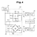
- the first magnetic sensor 20 includes a first bridge circuit 31 and a second bridge circuit 32, which is inclined by 45 degrees relative to the first bridge circuit 31.
- the first bridge circuit 31 is configured by magneto-resistive elements R1, R2, R3 and R4.
- the magneto-resistive element R1 and the magneto-resistive element R2 are connected in series.
- the magneto-resistive element R3 and the magneto-resistive element R4 are connected in series.
- the magneto-resistive elements R1 and R2 are connected parallel to the magneto-resistive elements R3 and R4.
- a node Na between the magneto-resistive element R1 and the magneto-resistive element R2 and a node Nb between the magneto-resistive element R3 and the magneto-resistive element R4 are connected to the first differential amplifier circuit 26.
- the second bridge circuit 32 is configured by magneto-resistive elements R5, R6, R7 and R8.
- the magneto-resistive element R5 and the magneto-resistive element R6 are connected in series.
- the magneto-resistive element R7 and the magneto-resistive element R8 are connected in series.
- the magneto-resistive elements R5 and R6 are connected parallel to the magneto-resistive elements R7 and R8.
- a node Nc between the magneto-resistive element R5 and the magneto-resistive element R6 and a node Nd between the magneto-resistive element R7 and the magneto-resistive element R8 are connected to the second differential amplifier circuit 27.
- the power supply circuit 24 applies voltage having a predetermined level to the first bridge circuit 31 and the second bridge circuit 32.
- the resistance of each magneto-resistive element R1 to R8 varies in accordance with the magnetic field (more accurately, the orientation of magnetic flux).
- the potentials at the nodes Na, Nb, Nc, and Nd vary as the orientation of the magnetic flux of the first magnet 17 shifts when the first driven gear 15 rotates.
- the first bridge circuit 31 provides the first differential amplifier circuit 26 with each potential at the nodes Na and Nb as a magnetic flux detection signal.
- the second bridge circuit 32 provides the second differential amplifier circuit 27 with each potential at the nodes Nc and Nd as a magnetic flux detection signal.
- the first and second differential amplifier circuits 26 and 27 differentially amplify the detection signals and generate a first analog signal A1 and a second analog signal A2.
- the first analog signal A1 is a sinusoidal signal and the second analog signal A2 is a cosine signal.
- the first and second analog signal A1 and A2 continuously vary in accordance with the rotational angle ⁇ of the first driven gear 15.
- the first analog signal A1 and the second analog signal A2 are provided to the microcomputer 23.
- the first driven gear 15 is rotated by 180 degrees whenever the drive gear 14 is rotated by 90 degrees.
- Each cycle of the first and second analog signals A1 and A2 corresponds to a 180 degree shift in the magnetic flux orientation of the first driven gear 15.
- the voltage of the first analog signal A1 output by the first magnetic sensor 20 is the same when the rotational angle ⁇ is 0 degrees and 180 degrees. This is the same for the second analog signal A2. Therefore, each cycle of the first and second analog signals A1 and A2 correspond to a 90 degree rotation of the drive gear 14, or a 180 degree rotation of the first driven gear 15.
- Connection lines P1 to P8 of Fig. 4 respectively correspond to pins P1 to P8 of an IC shown in Fig. 9.
- the second magnetic sensor 21 provides the third and fourth differential amplifier circuits 28 and 29 with the detection signals corresponding to a shift in the magnetic flux orientation of the second magnet 18 as the second driven gear 16 rotates.
- the third and fourth differential amplifier circuits 28 and 29 differentially amplifies the detection signals provided from the second magnetic sensor 21 to generate a third analog signal A3 and a fourth analog signal A4.
- the third analog signal A3 is a sinusoidal signal and the fourth analog signal A4 is a cosine signal.
- the third and fourth analog signals A3 and A4 continuously vary in accordance with the rotational angle ⁇ of the second driven gear 16.
- the third analog signal A3 and the fourth analog signal A4 are provided to the microcomputer 23.
- the second driven gear 16 is rotated by 180 degrees whenever the drive gear 14 is rotated by 95 degrees.
- Each cycle of the third and fourth analog signals A3 and A4 corresponds to a 180 degree shift in the magnetic flux orientation of the second driven gear 16.
- the voltage of the third analog signal A3 output by the second magnetic sensor 21 is the same when the rotational angle ⁇ is 0 degrees and 180 degrees. This is the same for the fourth analog signal A4. Therefore, each cycle of the third and fourth analog signals A3 and A4 correspond to rotation of about 95 degrees of the drive gear 14, or a 180 degree rotation of the second driven gear 16.
- the values of the rotational angle ⁇ of the drive gear 14 in Fig. 5B are values obtained by rounding off the first decimal place to the nearest whole number.
- the microcomputer 23 includes a CPU, a ROM, a RAM, and an A/D converter (not shown).
- the microcomputer 23 calculates the rotational angle ⁇ of the first driven gear 15 as shown in Fig. 5A from the combination of the voltages (output values) of the first and second analog signals A1 and A2 received from the first magnetic sensor 20 (first and second differential amplifier circuits 26 and 27).
- the microcomputer 23 calculates the rotational angle ⁇ of the second driven gear 16 as shown in Fig. 5B from the combination of the voltages (output values) of the third and fourth analog signals A3 and A4 received from the second magnetic sensor 21 (third and fourth differential amplifier circuits 28 and 29).
- the microcomputer 23 calculates the rotational angle ⁇ of the drive gear 14 based on the calculated rotational angles ⁇ and ⁇ and provides the calculated rotational angle ⁇ of the drive gear 14 to various vehicles systems (e.g., vehicle stability control system and electronic control suspension system).
- vehicles systems e.g., vehicle stability control system and electronic control suspension system.
- the rotation cycle of the second driven gear 16 is longer than the rotation cycle of the first driven gear 15. Therefore, when the steering wheel is rotated from a reference position (steering wheel rotation angle of 0 degrees) at which the rotational angle ⁇ of the first driven gear 15 and the rotational angle ⁇ of the second driven gear 16 are both 0 degrees, the value of " ⁇ - ⁇ "changes linearly in accordance with the steering wheel angle. Accordingly, the rotational angle ⁇ of the steering wheel within one cycle can be determined from the value of " ⁇ - ⁇ ".
- the microcomputer 23 calculates the rotational angle ⁇ of the drive gear 14, provides the rotational angle ⁇ to various vehicle systems, and stores the rotational angle ⁇ in a memory (not shown) as "previous rotational angle ⁇ ". The next time the steering wheel is rotated when the power is ON, the microcomputer 23 calculates the rotational angle ⁇ of the drive gear 14 once more. The microcomputer 23 calculates the difference between the present rotational angle ⁇ and the previous rotational angle ⁇ , which is stored in the memory, and compares the difference with a preset threshold value.
- the microcomputer 23 determines that either one of the first or the second magnetic sensor 20 and 21 is abnormal if the difference is greater than the threshold value.
- the microcomputer 23 activates a notification device such as an indicator or a buzzer arranged in an installment panel (not shown) to notify the vehicle occupant of the occurrence of an abnormality.
- a notification device such as an indicator or a buzzer arranged in an installment panel (not shown) to notify the vehicle occupant of the occurrence of an abnormality.
- An example of the threshold value is the varied amount of the rotational angle ⁇ when the steering wheel is rotated as fast as possible.
- the analog signals A1 to A4 of the first and second magnetic sensors 20 and 21 are provided to the microcomputer 23.
- the second magnetic sensor 21, which is functioning normally, generates normal third and fourth analog signals A3 and A4, as shown in Fig. 6.
- the first magnetic sensor 20, which is not functioning normally, generates erroneous first and second analog signals Ale and A2e, which have a small amplitude and a deviated phase. Therefore, the rotational angle of the first driven gear 15 calculated by the microcomputer 23 is not the normal rotational angle ⁇ and is an inaccurate angle ⁇ e containing error. Accordingly, the rotational angle of the drive gear 14, which is calculated from the rotational angle ⁇ e and the rotational angle P by the microcomputer 23, is not the normal rotational angle ⁇ and is an incorrect angle ⁇ e containing error.
- the vertical axis of Fig. 7 indicates the error between the rotational angles ⁇ e and ⁇ .
- the error forms a waveform generally resembling a cosine curve that fluctuates in 45 degree cycles.
- the calculated rotational angle ⁇ e deviates significantly from the actual rotational angle due to an algorism of the magnetic sensor.
- the rotational angle ⁇ e of the drive gear 14 in an abnormal state may be calculated as a value obtained by adding or subtracting the angle corresponding to one cycle of the detection signal, that is, the angle (90 degrees) corresponding to one cycle of the first and second analog signals A1 and A2 in the first magnetic sensor 20. If the abnormality of the magnetic sensor continues to be undetected, the microcomputer 23 continues to provide the vehicle systems with the rotational angle ⁇ e, which is significantly deviated from the normal value, as the normal value. A process for detecting the abnormality of the magnetic sensor at an early stage to resolve such a drawback is performed in the preferred embodiment.
- the microcomputer 23 When calculating the rotational angle ⁇ e of the drive gear 14, the microcomputer 23 also calculates radius values r1 and r2 from the voltages of the analog signals A1, A2, A3, and A4 in the same cycle using the following equation. Then, the microcomputer 23 compares the radius values r1 and r2 with an upper limit value CH and a lower limit value CL, which are determined in accordance with the characteristics property of the magnetic sensors 20 and 21.
- r ⁇ 1 voltage of first analog signal A ⁇ 1 ⁇ e 2 + voltage of second analog signal A ⁇ 2 ⁇ e 2
- r ⁇ 2 voltage of third analog signal A ⁇ 3 2 + voltage of fourth analog signal A ⁇ 4 2
- the radius values r1 and r2 are substantially the same if the corresponding magnetic sensors 20 and 21 are normal.
- the microcomputer 23 determines that the corresponding magnetic sensors 20 and 21 are abnormal if the radius values r1 and r2 are greater than the upper limit value CH or smaller than the lower limit value CL. This process may be referred to as individual output value check or radius check conducted on each magnetic sensor.
- Fig. 8 shows a locus r1 of the voltages of the first and second analog signals A1 and A2 generated by the first magnetic sensor 20 during one cycle and plotted in an orthogonal coordinate system in which the voltages of the first and second analog signals A1 and A2 are respectively indicated by the vertical axis and the horizontal axis.
- Fig. 8 also shows a locus r2 for of the voltages of the third and fourth analog signals A3 and A4 generated by the second magnetic sensor 21 during one cycle and plotted in an orthogonal coordinate system in which the voltages of the third and fourth analog signals A3 and A4 are respectively indicated by the vertical axis and the horizontal axis.
- the radius values r1 and r2 indicate the distances from the origin O to the loci r1, r2, respectively.
- the second magnetic sensor 21 is functioning normally.
- the radius value r2 is substantially constant, and the locus r2 is more or less a perfect circle.
- the radius value r1 continuously varies in the abnormal first magnetic sensor 20.
- the locus r1 forms an ellipse. Circles formed by the upper limit value CH, which is overlapped with the locus r2, and the lower limit value CL are also shown in Fig. 8.
- the microcomputer 23 determines that the second magnetic sensor 21 is functioning normally since the radius value r2 is always equal to the upper limit value CH.
- the microcomputer 23 determines that the first magnetic sensor 20 is abnormal if the radius value r1 is smaller than the lower limit value CL. For example, if the steering wheel is located at position S1 when the power goes ON and then rotated in the direction of arrow Y, the microcomputer 23 detects an abnormality in the first magnetic sensor 20 at the point the radius value r1 becomes smaller than the lower limit value CL, that is, at the point the steering wheel reaches position S2. Referring to Fig. 7, if the power goes ON when the steering wheel is located at position S1, at which a significant deviation has occurred as described above, and the steering wheel is then rotated, an abnormality in the magnetic sensor is detected when the steering wheel reaches position S2 at which the significant deviation occurs next.
- the rotational angle required for the steering wheel until the abnormality is detected from when the power goes ON is 13.3 degrees. That is, under the above circumstances, an abnormality in the magnetic sensor is detected when the steering wheel is rotated by 13.3 degrees to position S2 from position S1 during the radius check. Since a significant deviation does not occur during the period the steering wheel is located between position S3 and position S1, the rotational angle ⁇ e, which contains an error from the rotational angle ⁇ , is output as a substantially normal value.
- the microcomputer 23 performs a radius ratio check as described below in addition to the radius check to detect an abnormality in a magnetic sensor that occurs when the power is OFF.
- the microcomputer 23 calculates the ratio r1/r2 for the radius values r1 and r2, and compares the ratio r1/r2 with a predetermined lower threshold value RL and a predetermined upper threshold value RH.
- the microcomputer 23 determines that the magnetic sensors 20 and 21 are both normal if the value of r1/r2 is between the lower threshold value RL and the upper threshold value RH.
- the microcomputer 23 determines that the first magnetic sensor 20 is abnormal if the r1/r2 is smaller than the lower threshold value RL, that is, when the radius value r1 is small.
- the microcomputer 23 determines that the second magnetic sensor 21 is abnormal if the r1/r2 is greater than the upper threshold value RH, that is, when the radius value r2 is small.
- the microcomputer 23 includes an abnormality detection circuit for continuously monitoring the ratio of the output values of the magnetic sensors and detecting the abnormality of the magnetic sensor.
- the lower threshold value RL and the upper threshold value RH are set to "0.87" and "1.15", respectively.
- the rotational angle of the steering wheel required from when the power goes ON for an abnormality to be detected may be changed in accordance with the setting of the lower threshold value RL and the upper threshold value RH.
- Fig. 8 if the steering wheel is located at position S1 when the power goes ON and then rotated in the direction of the arrow Y, an abnormality in the first magnetic sensor 20 is detected at position S4, at which the ratio r1/r2 of the radius values becomes smaller than the lower threshold value RL during the radius ratio check.
- the rotational angle (period T2 in Fig. 7) of the steering wheel required from when the power goes ON for detection of an abnormality is 3.0 degrees. That is, under the above circumstances, an abnormality in the magnetic sensor is detected when the steering wheel is rotated by 3.0 degrees from position S1 to position S4 during the radius ratio check.
- the length of the period T2 may be changed in accordance with the setting of the lower threshold value RL and the upper threshold value RH. For example, the period T2 becomes longer as the difference between the lower threshold value RL and the upper threshold value RH increases. This increases the rotational angle of the steering wheel that is required from when the power goes ON to detect an abnormality. On the other hand, the period T2 becomes shorter as the difference between the lower threshold value RL and the upper threshold value RH decreases. This decreases the rotational angle of the steering wheel that is required from when the power goes ON to detect an abnormality.
- the microcomputer 23 activates a notification device, such as an indicator or a buzzer arranged in an installment panel (not shown), and notifies the vehicle occupant of the abnormality in the magnetic sensor.
- a notification device such as an indicator or a buzzer arranged in an installment panel (not shown)
- the microcomputer 23 provides a prohibition signal to the vehicle systems, which execute control based on the rotational angle of the steering shaft, to prohibit the control of the vehicle systems.
- the preferred embodiment has the advantages described below.
- the microcomputer 23 detects the rotational angle ⁇ of the drive gear 14 and an abnormality in the magnetic sensor.
- an abnormality detection circuit for performing the radius ratio check to detect an abnormality in a magnetic sensor may be provided in addition to the microcomputer 23.
- the microcomputer 23 performs both the radius ratio check and the radius check in the preferred embodiment, but does not need to perform the radius check.
- the lower threshold value RL and the upper threshold value RH are not limited to the values of the preferred embodiment.
- the rotational angle of the steering wheel required from when the power goes ON to the detect an abnormality during the radius ratio check may be reduced by decreasing the difference between the lower threshold value RL and the upper threshold value RH.
- the difference between the lower threshold value RL and the upper threshold value RH is too small, this may increase the possibility of an abnormal condition being detected due to noise or a detection error.
- the ratio of the number of teeth in the drive gear 14, the first driven gear 15, and the second driven gear 16 is not limited to the values of the preferred embodiment.
Landscapes
- Physics & Mathematics (AREA)
- General Physics & Mathematics (AREA)
- Measurement Of Length, Angles, Or The Like Using Electric Or Magnetic Means (AREA)
- Transmission And Conversion Of Sensor Element Output (AREA)
Applications Claiming Priority (1)
| Application Number | Priority Date | Filing Date | Title |
|---|---|---|---|
| JP2006124102A JP2007298291A (ja) | 2006-04-27 | 2006-04-27 | 回転角度検出装置 |
Publications (1)
| Publication Number | Publication Date |
|---|---|
| EP1849683A1 true EP1849683A1 (fr) | 2007-10-31 |
Family
ID=38235240
Family Applications (1)
| Application Number | Title | Priority Date | Filing Date |
|---|---|---|---|
| EP07445015A Withdrawn EP1849683A1 (fr) | 2006-04-27 | 2007-04-17 | Détecteur d'angle de rotation |
Country Status (4)
| Country | Link |
|---|---|
| US (1) | US7358719B2 (fr) |
| EP (1) | EP1849683A1 (fr) |
| JP (1) | JP2007298291A (fr) |
| KR (1) | KR20070105862A (fr) |
Cited By (6)
| Publication number | Priority date | Publication date | Assignee | Title |
|---|---|---|---|---|
| EP2157409A2 (fr) * | 2008-08-22 | 2010-02-24 | Kabushiki Kaisha Tokai Rika Denki Seisakusho | Détecteur de position |
| EP2259016A1 (fr) * | 2008-03-25 | 2010-12-08 | Sanyo Denki Co., Ltd. | Codeur pour détecter une position absolue sans batterie |
| US8442787B2 (en) | 2010-04-30 | 2013-05-14 | Infineon Technologies Ag | Apparatus, sensor circuit, and method for operating an apparatus or a sensor circuit |
| CN105547142A (zh) * | 2014-10-09 | 2016-05-04 | 罗伯特·博世有限公司 | 用于探测在旋转构件处的旋转角度的传感器组件 |
| WO2019108316A1 (fr) * | 2017-11-29 | 2019-06-06 | Allegro Microsystems, Llc | Capteur de champ magnétique permettant l'identification d'une condition d'erreur |
| EP3739298A1 (fr) * | 2019-05-14 | 2020-11-18 | Jtekt Corporation | Appareil de détection d'angle de rotation |
Families Citing this family (14)
| Publication number | Priority date | Publication date | Assignee | Title |
|---|---|---|---|---|
| CN101287959B (zh) * | 2005-01-25 | 2010-09-29 | 古河电气工业株式会社 | 旋转传感器 |
| DE102005061285A1 (de) * | 2005-12-20 | 2007-06-21 | Lemförder Electronic GmbH | Wähleinrichtung zum Schalten eines Fahrzeuggetriebes |
| JP4612577B2 (ja) * | 2006-03-31 | 2011-01-12 | ナイルス株式会社 | 回転角検出装置 |
| KR101011215B1 (ko) * | 2006-05-10 | 2011-01-26 | 키 세이프티 시스템즈 인코포레이티드 | 차량 도어용 구동 조립체와, 이를 구비한 차량 도어용 모듈장치 |
| JP2009192456A (ja) * | 2008-02-18 | 2009-08-27 | Panasonic Corp | 回転角度検出装置 |
| KR100957198B1 (ko) * | 2008-05-29 | 2010-05-11 | 한양대학교 산학협력단 | 구동축의 회전각 측정 시스템 |
| DE202009006227U1 (de) * | 2009-04-30 | 2010-10-21 | Dr. Fritz Faulhaber Gmbh & Co. Kg | Elektrischer Stellantrieb |
| DE102009031176A1 (de) * | 2009-06-29 | 2010-12-30 | Leopold Kostal Gmbh & Co. Kg | Winkelsensor |
| JP5460553B2 (ja) * | 2010-10-18 | 2014-04-02 | 株式会社東海理化電機製作所 | 回転角度検出装置 |
| JP5619677B2 (ja) * | 2011-06-01 | 2014-11-05 | 本田技研工業株式会社 | 磁気式回転角検出装置及びブレーキバイワイヤ型制動制御装置 |
| KR101484271B1 (ko) * | 2011-12-22 | 2015-01-19 | 주식회사 만도 | 전동식 파워 스티어링 시스템 및 그의 조향각 검증 방법 |
| US10215550B2 (en) | 2012-05-01 | 2019-02-26 | Allegro Microsystems, Llc | Methods and apparatus for magnetic sensors having highly uniform magnetic fields |
| JP6224349B2 (ja) * | 2013-05-15 | 2017-11-01 | 株式会社アイエイアイ | ステッピングモータ制御システム及びステッピングモータ制御方法 |
| JP7137449B2 (ja) * | 2018-11-30 | 2022-09-14 | ミネベアミツミ株式会社 | アブソリュートエンコーダ |
Citations (4)
| Publication number | Priority date | Publication date | Assignee | Title |
|---|---|---|---|---|
| US6507188B1 (en) * | 1998-12-04 | 2003-01-14 | Robert Bosch Gmbh | Device and method for detecting the relative position of a rotatable body |
| WO2004051192A2 (fr) * | 2002-12-05 | 2004-06-17 | Matsushita Electric Industrial Co., Ltd. | Detecteur d'angle de rotation |
| EP1445173A2 (fr) * | 2003-02-04 | 2004-08-11 | Kabushiki Kaisha Tokai Rika Denki Seisakusho | Capteur d'angles |
| WO2005043089A1 (fr) * | 2003-11-04 | 2005-05-12 | Nsk Ltd. | Dispositif de commande pour un appareil de direction de l'energie electrique |
Family Cites Families (5)
| Publication number | Priority date | Publication date | Assignee | Title |
|---|---|---|---|---|
| JP3654626B2 (ja) * | 2000-03-13 | 2005-06-02 | 株式会社ミツトヨ | 電磁誘導型位置検出装置 |
| JP4241012B2 (ja) | 2002-11-25 | 2009-03-18 | パナソニック株式会社 | 回転角度検出装置 |
| JP2004309222A (ja) | 2003-04-03 | 2004-11-04 | Tokai Rika Co Ltd | 回転角度検出装置 |
| JP2005031055A (ja) * | 2003-06-20 | 2005-02-03 | Yazaki Corp | 回転角度検出装置 |
| JP2005043089A (ja) * | 2003-07-23 | 2005-02-17 | Koyo Seiko Co Ltd | 軸受によって支持された軸装置及びトルク検出装置 |
-
2006
- 2006-04-27 JP JP2006124102A patent/JP2007298291A/ja active Pending
-
2007
- 2007-04-11 US US11/733,924 patent/US7358719B2/en not_active Expired - Fee Related
- 2007-04-17 EP EP07445015A patent/EP1849683A1/fr not_active Withdrawn
- 2007-04-24 KR KR1020070039643A patent/KR20070105862A/ko not_active Application Discontinuation
Patent Citations (5)
| Publication number | Priority date | Publication date | Assignee | Title |
|---|---|---|---|---|
| US6507188B1 (en) * | 1998-12-04 | 2003-01-14 | Robert Bosch Gmbh | Device and method for detecting the relative position of a rotatable body |
| WO2004051192A2 (fr) * | 2002-12-05 | 2004-06-17 | Matsushita Electric Industrial Co., Ltd. | Detecteur d'angle de rotation |
| EP1445173A2 (fr) * | 2003-02-04 | 2004-08-11 | Kabushiki Kaisha Tokai Rika Denki Seisakusho | Capteur d'angles |
| WO2005043089A1 (fr) * | 2003-11-04 | 2005-05-12 | Nsk Ltd. | Dispositif de commande pour un appareil de direction de l'energie electrique |
| EP1684051A1 (fr) * | 2003-11-04 | 2006-07-26 | NSK Ltd. | Dispositif de commande pour un appareil de direction de l'energie electrique |
Cited By (12)
| Publication number | Priority date | Publication date | Assignee | Title |
|---|---|---|---|---|
| EP2259016A1 (fr) * | 2008-03-25 | 2010-12-08 | Sanyo Denki Co., Ltd. | Codeur pour détecter une position absolue sans batterie |
| EP2259016A4 (fr) * | 2008-03-25 | 2017-03-29 | Sanyo Denki Co., Ltd. | Codeur pour détecter une position absolue sans batterie |
| EP2157409A2 (fr) * | 2008-08-22 | 2010-02-24 | Kabushiki Kaisha Tokai Rika Denki Seisakusho | Détecteur de position |
| EP2157409A3 (fr) * | 2008-08-22 | 2014-05-07 | Kabushiki Kaisha Tokai Rika Denki Seisakusho | Détecteur de position |
| US8442787B2 (en) | 2010-04-30 | 2013-05-14 | Infineon Technologies Ag | Apparatus, sensor circuit, and method for operating an apparatus or a sensor circuit |
| DE102011017698B4 (de) * | 2010-04-30 | 2014-10-30 | Infineon Technologies Ag | Vorrichtung, Sensorschaltung und Verfahren zum Betreiben einer Vorrichtung oder einer Sensorschaltung |
| CN105547142A (zh) * | 2014-10-09 | 2016-05-04 | 罗伯特·博世有限公司 | 用于探测在旋转构件处的旋转角度的传感器组件 |
| WO2019108316A1 (fr) * | 2017-11-29 | 2019-06-06 | Allegro Microsystems, Llc | Capteur de champ magnétique permettant l'identification d'une condition d'erreur |
| US10921373B2 (en) | 2017-11-29 | 2021-02-16 | Allegro Microsystems, Llc | Magnetic field sensor able to identify an error condition |
| EP3885710A1 (fr) * | 2017-11-29 | 2021-09-29 | Allegro MicroSystems, LLC | Capteur de champ magnétique permettant l'identification d'une condition d'erreur |
| EP3739298A1 (fr) * | 2019-05-14 | 2020-11-18 | Jtekt Corporation | Appareil de détection d'angle de rotation |
| US11408754B2 (en) | 2019-05-14 | 2022-08-09 | Jtekt Corporation | Rotation angle detection apparatus |
Also Published As
| Publication number | Publication date |
|---|---|
| KR20070105862A (ko) | 2007-10-31 |
| JP2007298291A (ja) | 2007-11-15 |
| US7358719B2 (en) | 2008-04-15 |
| US20070252590A1 (en) | 2007-11-01 |
Similar Documents
| Publication | Publication Date | Title |
|---|---|---|
| US7358719B2 (en) | Rotational angle detector | |
| EP2477003B1 (fr) | Dispositif de détection d'angle de rotation | |
| US8933692B2 (en) | Rotation angle detection device | |
| EP1783036B1 (fr) | Détecteur d'angle de rotation | |
| JP6561329B2 (ja) | 回転検出装置 | |
| US7073398B2 (en) | Apparatus for detecting the rotation angle of a rotational body | |
| US8710831B2 (en) | Rotation angle detecting device | |
| JP7178560B2 (ja) | 磁気センサ | |
| EP1845352A1 (fr) | Dispositif de detection d angle et de couple de rotation | |
| JP2006220529A (ja) | 絶対回転角度およびトルク検出装置 | |
| JP2018151180A (ja) | シフト位置検出装置 | |
| US6687647B2 (en) | Rotation-angle detecting device capable of precisely detecting absolute angle | |
| JP6741913B2 (ja) | 磁気センサこれを用いた回転検出装置 | |
| US20230112736A1 (en) | Failure detection device for steering angle sensor, and control method therefor | |
| JP2004331050A (ja) | トルクセンサ | |
| JP2007256140A (ja) | 回転角度・回転トルク検出装置 | |
| WO2007094196A1 (fr) | Detecteur de couple et detecteur d'angle de rotation | |
| CN100501311C (zh) | 尤其用于地面输送机械的电转向装置的旋转角传感器 | |
| JP2006275558A (ja) | 絶対回転角検出機能付きトルク検出装置 | |
| JP2018115890A (ja) | シフト位置検出装置 | |
| JP2018146483A (ja) | 磁気センサ | |
| KR20110051933A (ko) | 차량의 조향인식을 위한 센서 보정장치 | |
| JP2021050962A (ja) | 回転検出装置 | |
| KR102311493B1 (ko) | 토크 센서 및 토크 신호 처리 방법 | |
| JP2003004426A (ja) | 回転角度検出装置 |
Legal Events
| Date | Code | Title | Description |
|---|---|---|---|
| PUAI | Public reference made under article 153(3) epc to a published international application that has entered the european phase |
Free format text: ORIGINAL CODE: 0009012 |
|
| AK | Designated contracting states |
Kind code of ref document: A1 Designated state(s): AT BE BG CH CY CZ DE DK EE ES FI FR GB GR HU IE IS IT LI LT LU LV MC MT NL PL PT RO SE SI SK TR |
|
| AX | Request for extension of the european patent |
Extension state: AL BA HR MK YU |
|
| 17P | Request for examination filed |
Effective date: 20080430 |
|
| AKX | Designation fees paid |
Designated state(s): CZ DE FR GB SE |
|
| 17Q | First examination report despatched |
Effective date: 20101202 |
|
| STAA | Information on the status of an ep patent application or granted ep patent |
Free format text: STATUS: THE APPLICATION IS DEEMED TO BE WITHDRAWN |
|
| 18D | Application deemed to be withdrawn |
Effective date: 20110413 |