EP1847004B1 - Tragbare batterielade- und audioeinheit - Google Patents
Tragbare batterielade- und audioeinheit Download PDFInfo
- Publication number
- EP1847004B1 EP1847004B1 EP06720425A EP06720425A EP1847004B1 EP 1847004 B1 EP1847004 B1 EP 1847004B1 EP 06720425 A EP06720425 A EP 06720425A EP 06720425 A EP06720425 A EP 06720425A EP 1847004 B1 EP1847004 B1 EP 1847004B1
- Authority
- EP
- European Patent Office
- Prior art keywords
- signal receiving
- power
- receiving unit
- receptacle
- unit
- Prior art date
- Legal status (The legal status is an assumption and is not a legal conclusion. Google has not performed a legal analysis and makes no representation as to the accuracy of the status listed.)
- Expired - Fee Related
Links
- 238000012544 monitoring process Methods 0.000 claims 1
- 230000001681 protective effect Effects 0.000 abstract description 8
- 238000010276 construction Methods 0.000 description 9
- 239000000463 material Substances 0.000 description 5
- 239000000853 adhesive Substances 0.000 description 1
- 230000001070 adhesive effect Effects 0.000 description 1
- WYTGDNHDOZPMIW-RCBQFDQVSA-N alstonine Natural products C1=CC2=C3C=CC=CC3=NC2=C2N1C[C@H]1[C@H](C)OC=C(C(=O)OC)[C@H]1C2 WYTGDNHDOZPMIW-RCBQFDQVSA-N 0.000 description 1
- XAGFODPZIPBFFR-UHFFFAOYSA-N aluminium Chemical compound [Al] XAGFODPZIPBFFR-UHFFFAOYSA-N 0.000 description 1
- 229910052782 aluminium Inorganic materials 0.000 description 1
- 238000013500 data storage Methods 0.000 description 1
- 238000010586 diagram Methods 0.000 description 1
- 239000000428 dust Substances 0.000 description 1
- 239000012528 membrane Substances 0.000 description 1
- 229920001690 polydopamine Polymers 0.000 description 1
- 239000010409 thin film Substances 0.000 description 1
- XLYOFNOQVPJJNP-UHFFFAOYSA-N water Substances O XLYOFNOQVPJJNP-UHFFFAOYSA-N 0.000 description 1
Images


Classifications
-
- H—ELECTRICITY
- H01—ELECTRIC ELEMENTS
- H01M—PROCESSES OR MEANS, e.g. BATTERIES, FOR THE DIRECT CONVERSION OF CHEMICAL ENERGY INTO ELECTRICAL ENERGY
- H01M10/00—Secondary cells; Manufacture thereof
- H01M10/42—Methods or arrangements for servicing or maintenance of secondary cells or secondary half-cells
- H01M10/46—Accumulators structurally combined with charging apparatus
-
- H—ELECTRICITY
- H01—ELECTRIC ELEMENTS
- H01M—PROCESSES OR MEANS, e.g. BATTERIES, FOR THE DIRECT CONVERSION OF CHEMICAL ENERGY INTO ELECTRICAL ENERGY
- H01M50/00—Constructional details or processes of manufacture of the non-active parts of electrochemical cells other than fuel cells, e.g. hybrid cells
- H01M50/20—Mountings; Secondary casings or frames; Racks, modules or packs; Suspension devices; Shock absorbers; Transport or carrying devices; Holders
- H01M50/247—Mountings; Secondary casings or frames; Racks, modules or packs; Suspension devices; Shock absorbers; Transport or carrying devices; Holders specially adapted for portable devices, e.g. mobile phones, computers, hand tools or pacemakers
-
- H—ELECTRICITY
- H01—ELECTRIC ELEMENTS
- H01M—PROCESSES OR MEANS, e.g. BATTERIES, FOR THE DIRECT CONVERSION OF CHEMICAL ENERGY INTO ELECTRICAL ENERGY
- H01M50/00—Constructional details or processes of manufacture of the non-active parts of electrochemical cells other than fuel cells, e.g. hybrid cells
- H01M50/20—Mountings; Secondary casings or frames; Racks, modules or packs; Suspension devices; Shock absorbers; Transport or carrying devices; Holders
- H01M50/262—Mountings; Secondary casings or frames; Racks, modules or packs; Suspension devices; Shock absorbers; Transport or carrying devices; Holders with fastening means, e.g. locks
-
- H—ELECTRICITY
- H02—GENERATION; CONVERSION OR DISTRIBUTION OF ELECTRIC POWER
- H02J—CIRCUIT ARRANGEMENTS OR SYSTEMS FOR SUPPLYING OR DISTRIBUTING ELECTRIC POWER; SYSTEMS FOR STORING ELECTRIC ENERGY
- H02J7/00—Circuit arrangements for charging or depolarising batteries or for supplying loads from batteries
- H02J7/0042—Circuit arrangements for charging or depolarising batteries or for supplying loads from batteries characterised by the mechanical construction
-
- H—ELECTRICITY
- H04—ELECTRIC COMMUNICATION TECHNIQUE
- H04B—TRANSMISSION
- H04B1/00—Details of transmission systems, not covered by a single one of groups H04B3/00 - H04B13/00; Details of transmission systems not characterised by the medium used for transmission
- H04B1/06—Receivers
- H04B1/08—Constructional details, e.g. cabinet
-
- H—ELECTRICITY
- H04—ELECTRIC COMMUNICATION TECHNIQUE
- H04B—TRANSMISSION
- H04B1/00—Details of transmission systems, not covered by a single one of groups H04B3/00 - H04B13/00; Details of transmission systems not characterised by the medium used for transmission
- H04B1/06—Receivers
- H04B1/16—Circuits
- H04B1/20—Circuits for coupling gramophone pick-up, recorder output, or microphone to receiver
-
- H—ELECTRICITY
- H02—GENERATION; CONVERSION OR DISTRIBUTION OF ELECTRIC POWER
- H02J—CIRCUIT ARRANGEMENTS OR SYSTEMS FOR SUPPLYING OR DISTRIBUTING ELECTRIC POWER; SYSTEMS FOR STORING ELECTRIC ENERGY
- H02J7/00—Circuit arrangements for charging or depolarising batteries or for supplying loads from batteries
- H02J7/0068—Battery or charger load switching, e.g. concurrent charging and load supply
-
- Y—GENERAL TAGGING OF NEW TECHNOLOGICAL DEVELOPMENTS; GENERAL TAGGING OF CROSS-SECTIONAL TECHNOLOGIES SPANNING OVER SEVERAL SECTIONS OF THE IPC; TECHNICAL SUBJECTS COVERED BY FORMER USPC CROSS-REFERENCE ART COLLECTIONS [XRACs] AND DIGESTS
- Y02—TECHNOLOGIES OR APPLICATIONS FOR MITIGATION OR ADAPTATION AGAINST CLIMATE CHANGE
- Y02E—REDUCTION OF GREENHOUSE GAS [GHG] EMISSIONS, RELATED TO ENERGY GENERATION, TRANSMISSION OR DISTRIBUTION
- Y02E60/00—Enabling technologies; Technologies with a potential or indirect contribution to GHG emissions mitigation
- Y02E60/10—Energy storage using batteries
Definitions
- This invention generally relates to portable audio and battery pack charging equipment, as defined in the preamble of claim 1.
- Cordless power tools are frequently found and used in locations that do not have readily available or convenient sources of power. These locations include construction sites and partially completed buildings. At locations such as these, the battery operated tools provide an obvious advantage, but the battery packs eventually become depleted and need to be recharged. While some users bring a sufficient number of battery packs to last for a complete day, at some stage of the construction, there is generally at least temporary electrical service provided which may enable battery packs to be recharged on the construction site.
- the location of the temporary electrical service may be some distance from the actual work location and since the charger may be located some distance from the user, issues can arise that may prevent the successful completion of a charging operation. For example, another worker may take a battery pack for his own use, or the charger may simply be unplugged so that some other operation may be performed, since the number of available receptacles may be limited.
- Document EP 0 987 783 A2 depicts an audio equipment or a signal receiving unit which includes a housing, an audio circuitry installed within a housing, and a first protective bar flexibly connected to the housing.
- the audio equipment may also include a handle attached to the first protective bar, a second protective bar flexibly connected to the housing, and/or a connector assembly flexibly connecting the first protective bar to the housing.
- the connector assembly may include a flexible gasket preferable disposed between the first protective bar and the housing.
- power can be delivered from an alternating current source or from a battery pack. Also it is possible to charge a battery pack which can also serve as a battery pack for hand tools. But the disadvantage is that the user has to select the components receiving power which is sometimes very cumbersome.
- Document US 6 308 059 B1 discloses an audio unit which can also be powered by a battery pack.
- the battery pack can also be recharged but only for the use within this audio unit.
- the battery pack is not designed for being used in hand tools.
- the problem of the invention is create a solution for an apparatus of prior art, such as EP 0 987 783 A2 which could make it possible to automatically recognize if a source of AC power is disposable or not and automatically switch power to the signal receiving unit either from the source of AC power or from said battery pack without taking in account that any exceeding losses in a circuit for transmitting the power to the signal receiving unit will occur. Also it should be possible to use an auxiliary audio source.
- the invention discloses an apparatus as defined in claim 1, which provides an audio output and charges removable battery packs as well as providing a number of AC receptacles for powering other tools and the like when the unit is connected to a source of AC power.
- the unit can also provide DC power.
- the AC power drives the audio unit which may be a radio or a combination radio and CD player and the AC source also powers a charger which recharges a battery pack if a battery pack is inserted into the charger receptacle.
- the radio may be powered by a battery pack when it is placed in the charger receptacle.
- a relay When the unit is connected to a source of AC power, a relay is opened to isolate the radio unit from the charger and battery pack.
- Other embodiments can include one or more other audio and video devices such as a satellite radio, a digital audio player, a DVD player, a VCD player and a TV set.
- the unit has a unique protective frame structure that is connected to the housing of the unit.
- the preferred embodiment of the present invention also has a circuit that includes a relay that is adapted to isolate the battery pack and charger from the audio unit when a relay coil senses that AC power is being applied to the audio unit. If AC power is not sensed, the relay is closed so that a battery pack can drive the audio unit.
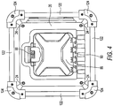
- a preferred embodiment of a portable battery charging an audio unit is shown in the drawings and which includes a housing, indicated generally at 10, which is in the form of a cube, although it could be a cuboid if desired, as well as some other shaped volume. As illustrated, it includes a front face or wall 12, a left side face or wall 14, a top surface 16, a rear wall 20 (see FIG. 4 ) and a right side face or wall 22.
- the housing 10 is preferably made of a tough plastic or other molded material, and may be comprised of a few or several parts that structurally fit together in a rugged strong unit.
- the front and back walls 12 and 20 may be generally flat unitary pieces which are connected together to one or more molded or otherwise formed front, top, bottom and rear walls that may be formed as one, two, or more components that are connected together with hex- head bolts or screws 24.
- the housing 10 is in the shape of a cube, i.e., the size of each wall is generally the same, the housing may also be a cuboid where one or more of the length, height and width dimensions may be greater than the others, i.e., a rectangular box-like shape, or a more unusual volume may be defined by the walls of the housing.
- the preferred embodiment has an audio unit, indicated generally at 30, which is located in the front face 12 of the unit.
- the audio unit comprises a radio that has a control panel 32 with a volume control 34, a tuning control 36, a display 38 for displaying the station identification as well as the current time.
- a CD player is also provided as part of the unit 30 and a CD tray 46 is positioned above the control panel 32.
- Speakers 56, 58, 60 and 62 are also provided and are located below the control panel 32.
- the unit can be connected or plugged into a source of AC power using a cord 70 having a 3-prong plug 72 as best shown in FIG. 6 .
- the unit has a cord wrap structure comprising four outwardly extending flanges 74 that are arranged in a square around which the cord can be wrapped for storage.
- the flanges each have a base portion 76 for mounting to the sidewall 14 and are connected thereto by screws 78 or the like. It should also be understood that the flanges 74 may be integrally formed in the sidewall 14 if desired.
- a fuse 80 for the circuitry to be described is accessible on the left side wall 14 as is a DC receptacle or socket 82 which is protected from the elements by a removable flexible plug that is preferably made of rubber or like material which can be inserted into the receptacle opening.
- a 2 channel stereo mini plug receptacle 83 is located adjacent the fuse 30 which can be used to input an auxiliary audio source that can be played through the unit. The receptacle 83 is therefore connected to the audio unit 30 as shown in FIG. 9 .
- a nameplate 85 is mounted to the left side wall 14, by four screws including the two top screws 87.
- auxiliary audio source in the receptacle 83 can be detected and thereby be selected as the source for playing, or a switch 87 can be provided on the face plate 32 for selecting the integral audio unit or the unit connected to the auxiliary receptacle.
- the unit has a charger 84 internally located in the housing which is accessible through a charger door 86 as shown in FIG. 4 .
- a handle 88 is provided at its upper end which engages a complimentary surface to hold the door shut, but which can be readily opened by a user without difficulty.
- a hinge 90 on the lower end of the door enables the door to be opened to reveal a holding chamber 92 that has a receptacle 94 at the bottom of the chamber 92 as shown in FIG. 5 .
- the configuration of the receptacle 94 is complimentary to receive a battery pack such as those marketed by the Robert Bosch Tool Corporation.
- a number of spring clips 96 are also provided to retain the battery pack in place while it is charging, which requires the cord 78 to be connected to a source of AC power.
- a pair of duplex AC outlets 100 are located beneath doors 102 (only one of which is shown) that are hinged at the top of the outlet pair. While they may be standard duplex receptacles, it is preferred that they be ground fault circuit interrupters to provide an extra measure of safety for the users, particularly given the fact that the unit may be subjected to harsh weather conditions. As is standard for ground fault circuit interrupters, a reset button 104 and test button 106 are provided.
- the top face of the unit 18 has a handle 108 that is formed by a generally hemispherical recess 110 that has a bridging portion 112 that extends across the recess and which together define the handle 108 that can be used to carry the unit. It should be apparent that the size of the recess be large enough so that the user can insert his hand easily into the recess to grab the bridging portion 112.
- the unit has a frame structure, indicated generally at 120, which is shown in virtually all of the drawings, but is best shown in FIGS. 2 , 4 and 8 .
- the frame structure 120 is larger than the housing 10 in every direction and thereby provides a protective structure for the housing itself, as well as the components that are present on each of the front, rear and side faces of the housing.
- the form of the frame structure 20 is that of an open faced cube in the preferred embodiment, but could also be an open faced cuboid if desired.
- the frame structure has a number of elongated cylindrical rods 122 that are preferably made of hollow aluminum. The rods extend in spaced relation to the interface of each two walls as is apparent from the drawings.
- each of the connectors has a pair of set screws 126 that fit within openings in the connector 124 and which engage the side of a cylindrical rod 122 in either the horizontal or vertical direction as shown in these drawings and which has a hex head screw 128 that is positioned to engage the rod 122 oriented in the direction transverse to the horizontal and vertical direction as shown in FIGS. 2 and 4 .
- the set screw 128 may engage the inside diameter of the hollow rod 122 or it may engage a plug or other member that is inserted into each end of such transverse to the cylindrical rods 122, such that a secure attachment of the connector to the rod is achieved. With regard to the screws 126, they may merely tighten against the outer surface of the rods in which they contact, or they may be screwed into the side of the rods.
- the housing has an elongated recess 130 located at the corner of the top and sides of the housing as well as the bottom and sides of the housing.
- a shorter cylindrical rod preferably having the same construction and outside diameter 132 fits within each recess and is secured at opposite ends by fitting into correspondingly sized openings in the housing.
- the frame structure 120 is connected to these rods 132 by connecting links 134 which have openings in opposite ends through which rods 122 and 132 may pass.
- the links 134 are preferably made of the same material as the connectors 124 so that they will not be easily damaged by the typically rough treatment that the unit may receive on a construction site.
- the audio unit 30 is shown being connected to the cord 70 via fuse 80 and lines 140 and 142.
- a ground 144 also extends from the outlets 100 to the plug 72.
- Lines 140 and 142 also extend to the outlets 100 as well as to the charger 84, with the charger 84 having output lines 146 and 148 that extend to the receptacle 94 into which a removable battery can be inserted.
- Lines 146 and 148 also extend to a relay 150 that is controlled by a relay coil 152 which senses whether current is flowing in the lines 140 and 142.
- the relay 150 is a normally closed relay which is opened when the plug 72 is connected to a source of AC power which means that the audio unit is being driven by the AC power source. It should be understood that the audio unit may actually run on DC voltage and that the audio unit may have an internal voltage converter as part of its construction.
- Another converter 154 may be provided to power the DC outlet 82.
- the charger 84 is operational to charge the removable battery if it is placed in the receptacle 94 and the outlets 100 are available to supply power to other tools, lights or the like, as is the DC outlet 82. If the plug 72 is removed from AC power, the relay 150 will be close circuited so that the removable battery will be connected to the audio unit and can power the audio unit.
- the charger is incapable of powering the audio unit when the relay is open circuited as shown in the drawing and is incapable of powering the audio unit 30 when AC power is not applied to the circuit inasmuch as the charger 84 does not have a resident battery or other power source other than AC power through the lines 140 and 142.
- audio units 30 that comprise a radio and also suggest a combination of a radio and a CD player
- other audio as well as video sources can also be incorporated into the unit.
- a portable digital audio player is shown mounted to the side wall 14. While it is not strictly visible in this drawing for the reason that it is contained in an enclosure 162 that has a window 164 for viewing the display of such a player as well as an opening 166 which preferably contains a transparent flexible membrane for limiting the entrance of dust and water into the interior of the enclosure.
- the illustrated enclosure 160 is particularly designed for use with a digital audio player.
- Such digital audio players might play a variety of formats, such as MP3, WMA, or AAC audio formats. They might be devoted digital audio players, or might also be other types of devices, such as PDAs or cell phones, that have this functionality built in.
- the enclosure 162 has a base portion 168 and a cover portion 170 with the base and cover being attached to one another by hinges 172 and a latch mechanism 174.
- the latch mechanism has a hook 176 that engages a retaining surface (not shown) with the latch mechanism 176 being slidable in a slot in the cover to lock and unlock the cover from the base portion 168.
- the digital audio player 160 has a connector (not shown) that is configured to interconnect with a second connector 178 in the base portion 168 when the digital audio player is placed in a cradle structure defined by a bottom surface 180 and curved side surfaces 182.
- Digital audio players are marketed with different models having different data storage capacities, and the thickness of them can vary accordingly. For this reason, a number of flexible resilient pads may be provided with the enclosure 162, including the pad 184 illustrated. The pad 184 may be placed in the enclosure so that the digital audio player to properly align it so that its connector will fit into the connector 178 and be held in place to prevent it from being damaged if the unit 10 is jostled or dropped, for example.
- each of the pads there will be several pads 184 of varying thicknesses so that the user can insert or attach the correct one to support it in the base portion 168.
- each of the pads have an adhesive backing which is covered by a thin film that can be removed so that the pad can be attached to the inside surface of the base portion 168.
- the back of the base portion 168 has a generally cylindrical power plug that is configured to fit in the 12 volt adaptor 82 as shown in FIG. 6 , for the purpose of providing power to the digital audio player.
- a 2-channel stereo mini-plug 188 is also provided to fit in the mini plug receptacle 83 shown in FIG. 6 and this is also interconnected with the connector 178 so that the digital audio player signals can be communicated to the amplifier in the audio unit 30 as shown in FIG. 9 enabling the amplifier to drive the speakers 60 and 62 as is desired.
- a toggle switch may be provided on the face plate 32 which selects either the radio receiver or the input from the mini plug receptacle 83.
- a bracket 190 having holes 192 on each end is provided and is connected to the side wall 14 by removing the screws 87 and placing the bracket overlying the name plate and thereafter replacing the screws 87 to mount the bracket 190 to the side wall.
- the bracket has a thicker outer periphery defining a recess 193 and an opening 194 is provided in the middle of the bracket 190 which is configured to receive a latch member 196 that is configured to be inserted into the hole 194 to latch the same.
- the latch 196 is formed as a part of an elongated sliding tab 198 that fits within a recess 200 that is preferably formed in the base portion 168 and which is also preferably a part of the latch 196.
- One end 202 of the sliding tab 198 extends outwardly beyond the end of the recess 200 and is available to be pushed inwardly so that the latch 196 can disengage from the hole 194 and enable the enclosure 162 to be removed from the side wall 14.
- the construction of the sliding tab 198 is shown in FIGS.
- the sliding tab 198 be made of ABS or other slightly flexible material that is capable of providing the necessary spring or biasing force. It should be understood that the dimensions of the sliding tab are such that the end 206 must be in contact with the end of the recess 200 and thereby be loaded so that a biasing force is normally applied to the latch 196 when it is installed in the enclosure 162.
- FIGS. 17 and 18 Another embodiment of the present invention is shown in FIGS. 17 and 18 wherein a satellite radio receiver 210 is illustrated and is configured so that it has a bottom connector that engages a connector similar to the connector 178 of FIG. 14 .
- the enclosure is in the form of a base portion 212 that is similar to the base portion 168 but which does not have a front cover and is therefore not completely enclosed.
- the satellite receiver 210 is preferably a unitary product that may be removed from the unit 10 so that it can be connected to a similar bracket in a user's motor vehicle, for example, the controls for operation of the radio are contained in the radio unit itself, except perhaps for an external volume control that is associated with the amplifier in the audio unit 30. It is also contemplated and is within the scope of the present invention that satellite radio unit may be the only audio receiver provided in the unit 10.
- FIG. 19 Still another embodiment is shown in FIG. 19 , where the unit has an audio and video player, indicated generally at 214, which is located in the front face 12 of the unit.
- the player comprises a video display 216 as a part of the control panel 32 with a volume control 34, and a tuning control 36.
- a CD player, DVD player and/or VCD player can be provided and a tray 46 is positioned above the control panel 32.
- the display 216 may also be a part of a TV receiver.
- this embodiment can be configured to accept audio and video signals from a portable audio and video source such as a portable DVD player or other video source and that the display 216 can then be used with the portable player.
Claims (18)
- Vorrichtung, umfassend:- ein Gehäuse (10) mit einer Anzahl von Wänden (12, 14, 20, 22), einem Oberteil (16) und einem Unterteil;- ein Ladegerät (84), welches in besagtem Gehäuse (10) zum Laden einer entnehmbaren Batteriepackung der Art, die für das Betreiben wiederaufladbarer Handgeräte und anderer Geräte verwendet wird, angeordnet ist;- einen Aufnahmeanschluss (94), welche wirkmäßig mit besagtem Ladegerät (84) verbunden ist, und welcher dazu in der Lage ist, eine entnehmbare Batteriepackung, die durch besagtes Ladegerät (84) zu laden ist, aufzunehmen;- eine in besagtem Gehäuse (10) angeordnete Signalempfangseinheit (30), welche einen Verstärker zur Erzeugung von Audio- und/oder Videosignalen aufweist;- ein Kabel (70) und einen Stecker (72) zum Verbinden der besagten Vorrichtung mit einer Wechselstromquelle;- eine erste Schaltung (80, 140, 142) zum Verbinden des besagten Kabels (70) mit besagtem Ladegerät (84) und besagter Signalempfangseinheit (30), wobei ein Wechselstrom an besagte Signalempfangseinheit (30) zum Antreiben derselben angelegt wird, und wobei außerdem Wechselstrom an besagtes Ladegerät (84) angelegt wird;
dadurch gekennzeichnet, dass besagte Vorrichtung weiterhin umfasst:- eine Eingangsbuchse (83) zum Empfang eines Hilfssignals und eine Gleichstromanschlussbuchse (82), die nebeneinander in einer der Seitenwände angeordnet sind, wobei besagte Eingangsbuchse (83) zum Empfang eines Hilfssignals wirkmäßig mit besagtem Verstärker in besagter Signalempfangseinheit (30) verbunden ist und dazu ausgelegt ist, Empfangs- und/oder Videosignale von einer Hilfsquelle, die mit besagter Eingangsbuchse (83) verbunden ist, zu erzeugen;- ein Relais (150), welches zwischen eine Batteriepackung in besagtem Aufnahmeanschluss (94) und besagter Signalempfangseinheit (30) geschaltet ist;- eine Relaisspule (152), welche zwischen besagtes Kabel (70) und besagter Signalempfangseinheit (30) geschaltet ist, wobei die Relaisspule (152) das Vorhandensein von an besagte Signalempfangseinheit (30) angelegtem Wechselstrom überwacht und besagtes Relais (150) zum Öffnen des Schaltkreises und Isolieren besagter Signalempfangseinheit (30) von besagter Batterie auslöst, wenn Wechselstrom an besagte Signalempfangseinheit (30) angelegt ist, und zum Schließen des Schaltkreises auslöst, wenn kein Wechselstrom an besagte Signalempfangseinheit (30) angelegt ist, wodurch besagte Batteriepackung in die Lage versetzt wird, besagte Signalempfangseinheit (30) anzutreiben, wenn an jene kein Wechselstrom angelegt ist,- wobei besagte Gleichstromanschlussbuchse (82) dazu ausgelegt ist, einen Netzstecker zum Antreiben besagter Hilfsquelle aufzunehmen. - Vorrichtung nach Anspruch 1, weiterhin umfassend einen Schalter zum Auswählen entweder der besagten Hilfsquelle oder der besagten Signalempfangseinheit (30) zum Erzeugen besagter Empfangs- und/oder Videosignale.
- Vorrichtung nach Anspruch 1, weiterhin umfassend eine Gehäuseaufnahme (162), welche dazu ausgelegt ist besagte Hilfquelle zu stützen und welche einen Netzstecker zum Verbinden mit besagter Gleichstromanschlussbuchse und einen Audiostecker umfasst, welcher dazu ausgelegt ist mit besagter Eingangsbuchse (83) zum Empfang eines Hilfssignals verbunden zu werden, einen Audioquellenverbinder (178) und Schaltungselemente zum Verbinden besagten Netzsteckers mit einer Hilfsquelle, die in besagter Gehäuseaufnahme (162) platziert ist, und besagte Hilfsquelle mit besagtem Signalempfangseinheitsverstärker (30).
- Vorrichtung nach Anspruch 3, wobei besagte Gehäuseaufnahme (162) weiterhin einen angelenkte eingeklinkte Abdeckung (170) zum Schützen der Hilfsquelle vor den Naturgewalten umfasst.
- Vorrichtung nach Anspruch 3, wobei besagte Gehäuseaufnahme (162) weiterhin einen Verriegelungsmechanismus (176) zum lösbaren Anbringen besagter Gehäuseaufnahme (162) mit besagtem Gehäuse (10) umfasst.
- Vorrichtung nach Anspruch 5, wobei besagter Verriegelungsmechanismus (176) eine dem Gehäuse (10) zugehörige Öffnung (194) und eine Riegeloberfläche (196) aufweist, die dazu ausgelegt ist, mit besagter Öffnung (194) einzurasten und selbige lösbar zu verriegeln.
- Vorrichtung nach Anspruch 6, wobei besagte Öffnung in einer fest mit besagtem Gehäuse (10) befestigten Halterung (190) angeordnet ist, wobei die Halterung (190) einen Zwischenraum zwischen ihrer zu besagter Öffnung (194) benachbarter Innenoberfläche und besagter Gehäuseoberfläche aufweist, der es besagter Riegeloberfläche (196) erlaubt, in die Öffnung (194) einzudringen und in besagter Halterung (190) in halternder Verbindung einzurasten.
- Vorrichtung nach Anspruch 7, wobei besagte Riegeloberfläche (196) Teil einer längsgestreckten Leiste (198) ist, die relativ zu besagter Halterung (190) verschiebbar ist, wobei besagte Leiste (198) für einen Nutzer zugänglich ist, um besagten Riegel (96) von besagtem Gehäuse (10) zu lösen.
- Vorrichtung nach Anspruch 8, wobei besagte Leiste (198) in einer Ausnehmung (200) in besagter Gehäuseaufnahme (162) verschiebbar ist.
- Vorrichtung nach Anspruch 8, weiterhin umfassend Mittel (204) zum Vorspannen besagter Leister (198) in verriegelndem Eingriff.
- Vorrichtung nach Anspruch 10, wobei besagte Vorspannmittel (204) einen flexiblen Teil besagter Leiste (198) in schlangenförmiger Ausgestaltung aufweisen, und wobei ein Endstück der Leiste (198) gegen besagte Gehäuseaufnahme (162) drückt, so dass die Abmessungen besagter Leiste (198) dazu führen, dass die schlangenförmige Ausgestaltung mit Spannung beaufschlagt wird, um eine Vorspannkraft bereitzustellen.
- Vorrichtung nach Anspruch 1, wobei besagte Hilfsquelle ein tragbares digitales Audiowiedergabegerät umfasst.
- Vorrichtung nach Anspruch 1, wobei besagte Hilfsquelle ein Satellitenradio umfasst.
- Vorrichtung nach Anspruch 1, wobei besagte Signalempfangseinheit (30) einen Fernsehempfänger umfasst.
- Vorrichtung nach Anspruch 1, wobei besagte Signalempfangseinheit (30) einen DVD-Spieler umfasst.
- Vorrichtung nach Anspruch 1, wobei besagte Signalempfangseinheit (30) einen Video-CD-Spieler umfasst.
- Vorrichtung nach Anspruch 1, wobei besagte Signalempfangseinheit (30) einen CD-Spieler umfasst.
- Vorrichtung nach Anspruch 1, wobei besagte Signalempfangseinheit (30) ein AM/FM-Radiogerät umfasst.
Applications Claiming Priority (2)
| Application Number | Priority Date | Filing Date | Title |
|---|---|---|---|
| US11/055,341 US8604752B2 (en) | 2003-10-14 | 2005-02-10 | Portable battery charging and audio unit |
| PCT/US2006/004256 WO2006086371A2 (en) | 2005-02-10 | 2006-02-06 | Portable battery charging and audio unit |
Publications (2)
| Publication Number | Publication Date |
|---|---|
| EP1847004A2 EP1847004A2 (de) | 2007-10-24 |
| EP1847004B1 true EP1847004B1 (de) | 2012-05-02 |
Family
ID=36709952
Family Applications (1)
| Application Number | Title | Priority Date | Filing Date |
|---|---|---|---|
| EP06720425A Expired - Fee Related EP1847004B1 (de) | 2005-02-10 | 2006-02-06 | Tragbare batterielade- und audioeinheit |
Country Status (5)
| Country | Link |
|---|---|
| US (1) | US8604752B2 (de) |
| EP (1) | EP1847004B1 (de) |
| CN (1) | CN101194405B (de) |
| CA (1) | CA2597495A1 (de) |
| WO (1) | WO2006086371A2 (de) |
Cited By (1)
| Publication number | Priority date | Publication date | Assignee | Title |
|---|---|---|---|---|
| DE102013113174A1 (de) * | 2013-11-28 | 2015-06-11 | Sick Ag | Sensor und Verfahren zum wahlweisen Anschließen von zwei unterschiedlichen Seiten |
Families Citing this family (49)
| Publication number | Priority date | Publication date | Assignee | Title |
|---|---|---|---|---|
| US6782618B2 (en) * | 2001-10-26 | 2004-08-31 | Glenn J. Luzzi | Adapter mandrel used in conjunction with premolded high voltage connectors and connector components |
| US7609027B2 (en) | 2001-11-09 | 2009-10-27 | Milwaukee Electric Tool Corporation | Electrical component, audio component, or electrical combination having a selectively connectable battery charger |
| US7989969B2 (en) | 2002-06-06 | 2011-08-02 | Black & Decker Inc. | Universal power tool battery pack coupled to a portable internal combustion engine |
| US8319357B2 (en) * | 2002-06-06 | 2012-11-27 | Black & Decker Inc. | Starter system for portable internal combustion engine electric generators using a portable universal battery pack |
| US7687926B2 (en) * | 2002-06-06 | 2010-03-30 | Black & Decker Inc. | Starter system for portable internal combustion engine electric generators using a portable universal battery pack |
| US7309928B2 (en) * | 2002-06-06 | 2007-12-18 | Black & Decker Inc. | Starter system for portable internal combustion engine electric generators using a portable universal battery pack |
| ES2308665T3 (es) * | 2005-05-19 | 2008-12-01 | Black & Decker Inc. | Radio, luz y suministro electrico de emergencia. |
| US7419038B2 (en) * | 2005-05-31 | 2008-09-02 | Great Stuff, Inc. | Reel and reel housing |
| US7696721B2 (en) * | 2005-11-08 | 2010-04-13 | Emerson Electric Co. | Switching method and apparatus for AC/DC powered corded/cordless appliance and related apparatus |
| US20080021634A1 (en) * | 2005-12-27 | 2008-01-24 | Diaz Melvin B | Latch apparatus for portable electronic devices |
| WO2008010801A2 (en) * | 2006-07-18 | 2008-01-24 | Gerald Pierce | Electrical energy source |
| US7600998B1 (en) * | 2006-08-15 | 2009-10-13 | Eric Pitchford | Portable heater with roll cage |
| US20080063936A1 (en) * | 2006-09-11 | 2008-03-13 | Hansen Leroy C | Portable Battery Power Supply |
| US8154857B2 (en) | 2007-01-04 | 2012-04-10 | Whirlpool Corporation | Appliance host with multiple service interfaces for coupling multiple consumer electronic devices |
| US7898812B2 (en) | 2007-01-04 | 2011-03-01 | Whirlpool Corporation | Alternative hosts for multiple adapters and multiple consumer electronic devices |
| US20080164758A1 (en) * | 2007-01-04 | 2008-07-10 | Mccoy Richard A | Electrical accessory charging compartment for a cabinet and retrofit components therefor |
| US7826203B2 (en) | 2007-01-04 | 2010-11-02 | Whirlpool Corporation | Transformative adapter for coupling a host and a consumer electronic device having dissimilar standardized interfaces |
| US7618295B2 (en) | 2007-01-04 | 2009-11-17 | Whirlpool Corporation | Adapter and consumer electronic device functional unit |
| US7686127B2 (en) | 2007-01-04 | 2010-03-30 | Whirlpool Corporation | Acoustic chamber as part of adapter or appliance |
| US7989980B2 (en) * | 2007-03-02 | 2011-08-02 | Blackman Tracy D | Portable self regenerating power system |
| US20090175458A1 (en) * | 2008-01-09 | 2009-07-09 | Kelly Smith | Subwoofer docking station |
| US8199958B2 (en) | 2008-05-22 | 2012-06-12 | Robert Bosch Gmbh | Battery charging jobsite audio apparatus |
| US8193943B2 (en) * | 2009-10-12 | 2012-06-05 | Mattel, Inc. | Handheld charge indicator assemblies for children's ride-on vehicles, and associated kits and methods |
| US8113346B1 (en) | 2010-08-12 | 2012-02-14 | Lai Deborah A | Waterproof music player storage device |
| US8878397B2 (en) | 2010-08-31 | 2014-11-04 | Great Stuff, Inc. | Electrical cord reel with control system to limit overheating |
| US8235552B1 (en) | 2011-02-25 | 2012-08-07 | Makita Corporation | Cordless flashlight and radio device |
| DE102011077112A1 (de) * | 2011-06-07 | 2012-12-13 | Robert Bosch Gmbh | Handwerkzeugaufbewahrungsvorrichtung |
| JP5670839B2 (ja) | 2011-06-30 | 2015-02-18 | 株式会社マキタ | ラジオ |
| US9525293B2 (en) | 2011-12-30 | 2016-12-20 | Makita Corporation | Battery charger having angled wall in battery receiving opening, and battery pack charging system and cordless power tool system including same |
| US9341403B2 (en) | 2012-07-11 | 2016-05-17 | Milwaukee Electric Tool Corporation | Cooler |
| US9781496B2 (en) | 2012-10-25 | 2017-10-03 | Milwaukee Electric Tool Corporation | Worksite audio device with wireless interface |
| GB2510149B (en) * | 2013-01-25 | 2015-11-11 | Technetix Bv | Electrical Device |
| US9693470B2 (en) * | 2013-06-14 | 2017-06-27 | Hitachi Koki Co., Ltd. | Electric device with surrounding protective frame |
| USD741795S1 (en) | 2013-10-25 | 2015-10-27 | Milwaukee Electric Tool Corporation | Radio charger |
| US10044197B2 (en) | 2013-12-12 | 2018-08-07 | Milwaukee Electric Tool Corporation | Portable power supply and battery charger |
| US10104795B2 (en) * | 2016-11-18 | 2018-10-16 | Illinois Tool Works Inc. | Protective assemblies for enclosures |
| USD825462S1 (en) | 2016-11-18 | 2018-08-14 | Illinois Tool Works Inc. | Protective frame for an electronic component |
| USD840925S1 (en) * | 2016-12-09 | 2019-02-19 | Black & Decker Inc. | Electrical device |
| GR1009222B (el) * | 2017-02-03 | 2018-02-15 | Στυλιανος Διογενη Δρανδακης | Ανακυκλωση ρευματος |
| CN207304039U (zh) * | 2017-07-07 | 2018-05-01 | 深圳市正浩创新科技有限公司 | 移动电源 |
| USD860646S1 (en) * | 2018-03-29 | 2019-09-24 | Canyon Party Rental, LLC | Portable cinema case |
| US10862176B2 (en) * | 2018-06-15 | 2020-12-08 | Florida Power & Light Company | Portable rechargeable battery pack with a selectable battery switch and state of charge display for cordless power tools |
| CN112385110B (zh) * | 2018-06-20 | 2024-01-19 | 创科无线普通合伙 | 具有通信能力的电池充电站 |
| JP7188935B2 (ja) * | 2018-08-17 | 2022-12-13 | 株式会社マキタ | 音声出力器 |
| USD951223S1 (en) * | 2019-04-12 | 2022-05-10 | Shenzhen Airsmart Technology Co., Ltd | FM radio and wireless speaker housing |
| USD936030S1 (en) | 2019-06-04 | 2021-11-16 | Milwaukee Electric Tool Corporation | Storage unit radio |
| US11205955B1 (en) | 2020-06-19 | 2021-12-21 | D'Amore Engineering, LLC | Current averaging audio amplifier |
| CN212623545U (zh) * | 2020-08-28 | 2021-02-26 | 中强光电股份有限公司 | 框架模块与投影装置 |
| USD965515S1 (en) | 2020-09-18 | 2022-10-04 | Ariens Company | Battery charger |
Family Cites Families (198)
| Publication number | Priority date | Publication date | Assignee | Title |
|---|---|---|---|---|
| US77073A (en) * | 1868-04-21 | James monach | ||
| US1511581A (en) | 1924-10-14 | bitter | ||
| US1518508A (en) | 1924-06-07 | 1924-12-09 | Julius B Rubenstein | Interchangeable battery system for radio sets |
| FR959148A (de) | 1946-12-06 | 1950-03-24 | ||
| US2591438A (en) * | 1947-04-24 | 1952-04-01 | Gen Electric | Portable radio receiver |
| US2473194A (en) * | 1948-03-04 | 1949-06-14 | Stromberg Carlson Co | Power supply switching system |
| US2582330A (en) * | 1949-02-08 | 1952-01-15 | John W Hautala | Portable electric light with battery charging bracket |
| US2565273A (en) | 1950-09-11 | 1951-08-21 | Sterlingworth Company | Battery charger |
| US2771560A (en) | 1956-01-25 | 1956-11-20 | Gen Electric | Combination switch and interlock for electrical devices |
| US2771559A (en) | 1956-01-25 | 1956-11-20 | Gen Electric | Portable clock radio |
| US3079510A (en) * | 1957-11-01 | 1963-02-26 | Licentia Gmbh | Dry shaving apparatus combining varying sources of power |
| DE1136764B (de) | 1958-01-21 | 1962-09-20 | Standard Elektrik Lorenz Ag | Schaltungsanordnung zur Gleichstrom-versorgung eines Verbrauchers aus dem Wechselstromnetz |
| US3214670A (en) | 1961-10-16 | 1965-10-26 | Schaf Jack | Apparatus for simultaneously charging a battery and operating a timer motor |
| US3267510A (en) | 1964-04-22 | 1966-08-23 | Amanda B Cote | Portable vacuum cleaner |
| US3525912A (en) | 1966-03-28 | 1970-08-25 | Scovill Manufacturing Co | Selectable power source for a motor driven appliance |
| US3458794A (en) * | 1967-06-07 | 1969-07-29 | Westinghouse Electric Corp | Rechargeable device with rotatable plug |
| US3521142A (en) * | 1967-11-13 | 1970-07-21 | Heath Co | Power supply system for portable television receiver |
| US3533119A (en) | 1968-03-06 | 1970-10-13 | Sunbeam Corp | Cordless portable electric appliance |
| US3824472A (en) * | 1973-01-24 | 1974-07-16 | Gen Delivery | Portable radio/tape recorder charging and locking system |
| GB1422759A (en) * | 1973-06-08 | 1976-01-28 | Wolf Geraete Gmbh | Battery power pack |
| US3852652A (en) | 1973-08-06 | 1974-12-03 | Motorola Inc | Rapid battery charging system and method |
| US3943423A (en) * | 1973-08-28 | 1976-03-09 | Hoffman Philip A | Battery charging circuit |
| CA1028659A (en) * | 1973-10-12 | 1978-03-28 | Kozo Yamamoto | Protective case for tape-recorder or radio-set |
| US3971889A (en) * | 1974-04-22 | 1976-07-27 | Hays Robert A | Portable bar adapted for mounting electronic equipment |
| US3984645A (en) | 1974-12-02 | 1976-10-05 | Kresch Warren J | Lightweight headset and retractable cord spool |
| US3962591A (en) * | 1974-12-23 | 1976-06-08 | The United States Of America As Represented By The Secretary Of The Army | Voltage doubler circuit |
| US3968417A (en) * | 1975-05-08 | 1976-07-06 | Lawrence Peska Associates, Inc. | Clock-radio with automatically selected battery power |
| US4050493A (en) | 1976-01-05 | 1977-09-27 | Jin Sul Cho | Ladies handbag and radio |
| US4045663A (en) | 1976-06-16 | 1977-08-30 | James W. Fair | Rechargeable flashlight assembly |
| JPS5341011U (de) * | 1976-09-14 | 1978-04-10 | ||
| US4095184A (en) * | 1976-11-01 | 1978-06-13 | Hochstein Peter A | Radio transceiver power booster |
| US4091318A (en) * | 1977-02-16 | 1978-05-23 | Motorola Inc. | Charger/converter console with reel arrangement |
| US4188585A (en) * | 1978-03-16 | 1980-02-12 | Cincinnati Electronics Corporation | Synchronized receiver power system |
| US4531798A (en) | 1982-03-29 | 1985-07-30 | Automation Industries, Inc. | Heavy-duty electrical connector |
| US4489268A (en) | 1983-01-05 | 1984-12-18 | General Electric Company | Rechargeable battery with separate charging terminal contact ring |
| US4645996A (en) * | 1985-10-25 | 1987-02-24 | General Electric Company | Rechargeable battery and electrical circuit for charging thereof |
| USD296243S (en) * | 1985-12-30 | 1988-06-14 | Skylite Industry Co., Ltd. | Combined portable light and radio |
| US4628242A (en) | 1985-12-30 | 1986-12-09 | General Electric Company | System for charging a rechargeable battery |
| USD307829S (en) * | 1986-01-16 | 1990-05-15 | Makio Hasuike | Suit-case |
| US4751452A (en) * | 1986-02-24 | 1988-06-14 | Cooper Industries | Battery operated power wrap tool |
| JPS6355609U (de) | 1986-09-25 | 1988-04-14 | ||
| US4811314A (en) * | 1987-04-13 | 1989-03-07 | Scosche Industries, Inc. | Portable compact disc player and vehicle audio apparatus with slidable tray for supporting compact disc player |
| DE3786170T2 (de) | 1987-10-06 | 1993-09-23 | Black & Decker Inc | Batteriesatz. |
| US4807292A (en) * | 1987-10-13 | 1989-02-21 | Bernard Sorscher | Apparatus for converting a motor vehicle plug-in audio unit into a remote playable unit |
| US4933988A (en) * | 1987-10-15 | 1990-06-12 | Thibault Gerard J | Audio receiver and detachable battery pack |
| USD310529S (en) | 1988-02-02 | 1990-09-11 | John Manufacturing Limited | Combined AM/FM radio, cassette player, spotlight and tool box |
| US4835409A (en) * | 1988-02-26 | 1989-05-30 | Black & Decker Inc. | Corded/cordless dual-mode power-operated device |
| JP2560410B2 (ja) | 1988-05-06 | 1996-12-04 | 日本電気株式会社 | 無線電話装置 |
| USD321513S (en) | 1988-08-30 | 1991-11-12 | Sony Corporation | Combined tape player and radio tuner |
| US4870702A (en) | 1988-09-26 | 1989-09-26 | Ghassan Azzouni | Adjustable portable console sleeve for radios |
| US5150031A (en) | 1988-09-30 | 1992-09-22 | Motorola, Inc. | Battery charging system |
| JPH02202252A (ja) | 1989-01-31 | 1990-08-10 | Toshiba Corp | コードレス電話装置の充電器 |
| JPH02246740A (ja) * | 1989-03-16 | 1990-10-02 | Toshiba Corp | 電源バックアップ回路 |
| USD320600S (en) | 1989-04-04 | 1991-10-08 | John Manufacturing Limited | Combined AM/FM radio, torch blinker and beam light with clip |
| US5193220A (en) * | 1989-06-02 | 1993-03-09 | Nec Corporation | Device for mounting an electronic part |
| US5283654A (en) * | 1989-07-12 | 1994-02-01 | Samsung Electronics Co. Ltd. | TV-radio converter using a same power supply |
| ATE116490T1 (de) | 1989-07-15 | 1995-01-15 | Kress Elektrik Gmbh & Co | Elektrowerkzeug. |
| US4993061A (en) * | 1989-07-20 | 1991-02-12 | Hsieh Sheng Yu | Portable miniature high fidelity stereo tape player and cordless radio telephone system |
| USD320210S (en) | 1989-09-15 | 1991-09-24 | Mbuthia David G | Combined radio, compass, flashlight and personal alarm |
| JP2736128B2 (ja) * | 1989-09-20 | 1998-04-02 | 株式会社東芝 | 無線通信装置 |
| US5235822A (en) | 1989-10-26 | 1993-08-17 | Leonovich Jr George A | Combined portable cooler with audio system |
| GB2239567A (en) | 1990-04-05 | 1991-07-03 | Technophone Ltd | Portable radio telephone useable with batteries of different types; battery charging |
| GB2242793B (en) | 1990-04-05 | 1994-08-10 | Technophone Ltd | Battery charging apparatus |
| US5146618A (en) | 1990-05-24 | 1992-09-08 | Wenner Jeffrey W | Automotive radio support and conversion apparatus |
| US5055986A (en) | 1990-10-22 | 1991-10-08 | Johnson Mary B | Combination light, radio and clock |
| USD332768S (en) * | 1990-10-24 | 1993-01-26 | Profile For Speed | Combined auxiliary bar and arm rests for attachment to a bicycle handle bar |
| USD327468S (en) * | 1990-10-30 | 1992-06-30 | Century Mfg. Co. | Portable, battery, power source |
| US5218284A (en) * | 1990-12-31 | 1993-06-08 | Motorola, Inc. | Integral battery charging and supply regulation circuit |
| EP0494780B1 (de) | 1991-01-11 | 1997-03-26 | Kabushiki Kaisha Toshiba | Adapter zur Versorgung eines transportablen Funktelefons mit Spannung |
| DE4104883A1 (de) | 1991-02-18 | 1992-08-20 | Braun Ag | Elektrisches geraet |
| DE4106557A1 (de) | 1991-03-01 | 1992-09-03 | Andreas Dipl Ing Maerten | Zusatzgeraet fuer autoradio bzw. auto-kassetten-radio |
| JP2737437B2 (ja) * | 1991-03-29 | 1998-04-08 | 日本電気株式会社 | 充電器 |
| US5172043A (en) | 1991-04-03 | 1992-12-15 | Gates Energy Products, Inc. | Energy using device |
| DE9104788U1 (de) | 1991-04-19 | 1991-06-13 | Grundig E.M.V. Elektro-Mechanische Versuchsanstalt Max Grundig Hollaend. Stiftung & Co Kg, 8510 Fuerth, De | |
| US5239687A (en) | 1991-05-06 | 1993-08-24 | Chen Shih Chung | Wireless intercom having a transceiver in which a bias current for the condenser microphone and the driving current for the speaker are used to charge a battery during transmission and reception, respectively |
| JP3398389B2 (ja) * | 1991-05-17 | 2003-04-21 | ソニー株式会社 | 電極装置 |
| US5317249A (en) * | 1991-07-15 | 1994-05-31 | Motorola, Inc. | Transmit mode detector in a battery charger |
| US5136229A (en) | 1991-07-15 | 1992-08-04 | Galvin Jay M | Power pack device |
| US5187422A (en) * | 1991-07-31 | 1993-02-16 | Stryker Corporation | Charger for batteries of different type |
| US5220269A (en) * | 1991-10-04 | 1993-06-15 | Innova Electronics Corporation | Power supply unit |
| US5369565A (en) | 1991-10-04 | 1994-11-29 | Innova Electronics Corp. | Modular power supply system |
| CA2079977A1 (en) | 1991-10-10 | 1993-04-11 | Brent A. Ledet | Drive sprocket systems for registration of spaced metal laminations across the width of plastic conveyor belts |
| US5272431A (en) | 1991-11-27 | 1993-12-21 | Nee Patrick W | Automatic power connector for recharging electric vehicles |
| DE4142628C1 (de) * | 1991-12-21 | 1993-05-06 | Dieter Braun | |
| US5254927A (en) | 1992-01-30 | 1993-10-19 | Chiang Chin Hsing | Battery charger with appliance plug socket |
| US5179747A (en) * | 1992-02-14 | 1993-01-19 | Zink Robert C | Pillow radio apparatus |
| US5369797A (en) | 1992-03-04 | 1994-11-29 | Tyree; James G. | Radio alarm clock with removable cassette player/recorder |
| JP3263855B2 (ja) | 1992-03-06 | 2002-03-11 | ソニー株式会社 | バッテリーパック |
| US5300875A (en) * | 1992-06-08 | 1994-04-05 | Micron Technology, Inc. | Passive (non-contact) recharging of secondary battery cell(s) powering RFID transponder tags |
| CA2098136C (en) | 1992-06-25 | 1996-11-12 | Peter John Yankura | Remote charging cradle for cordless telephone handset |
| CA2098468C (en) * | 1992-07-07 | 1998-09-01 | David J. Theobald | Method for battery charging |
| US5245269A (en) | 1992-08-17 | 1993-09-14 | Ncr Corporation | Battery temperature sensing apparatus |
| JP3387124B2 (ja) | 1992-09-02 | 2003-03-17 | ソニー株式会社 | カメラ一体型vtrの接続装置 |
| US5325040A (en) * | 1992-09-21 | 1994-06-28 | Motorola, Inc. | Method and apparatus for charging a battery powered electronic device |
| US5262710A (en) | 1992-10-26 | 1993-11-16 | Motorola, Inc. | Battery charger assembly |
| USD349116S (en) * | 1992-12-29 | 1994-07-26 | Pollyflame International B.V. | Radio |
| USD348461S (en) * | 1992-12-29 | 1994-07-05 | Pollyflame International B.V. | Radio |
| JPH06252820A (ja) | 1993-02-26 | 1994-09-09 | Sony Corp | 電源回路とそれを用いた無線通信装置 |
| US5870149A (en) * | 1993-03-12 | 1999-02-09 | Motorola, Inc. | Video/integrated land mobile dispatch radio and video unit |
| JPH07118677B2 (ja) | 1993-04-16 | 1995-12-18 | 日本電気株式会社 | 無線選択呼出受信機 |
| US5620242A (en) | 1993-04-19 | 1997-04-15 | Motorola, Inc. | Portable radio battery latch |
| USD358579S (en) * | 1993-05-27 | 1995-05-23 | Motorola, Inc. | Insert portion of a battery charger for a portable radio |
| GB2279827B (en) | 1993-06-02 | 1998-01-07 | Vtech Communications Ltd | Alternative power supply apparatus |
| US5396162A (en) * | 1993-06-03 | 1995-03-07 | Brilmyer; George | Portable battery charger |
| US5638540A (en) * | 1993-06-08 | 1997-06-10 | U.S. Robotics Mobile Communication Corp. | Portable computer/radio power management system |
| US5404419A (en) * | 1993-06-25 | 1995-04-04 | Artis, Jr.; Amos | Wall-mounted cordless dryer for the hands with battery charging circuit, AM/FM radio, and vertical positioning means |
| US5339956A (en) | 1993-06-28 | 1994-08-23 | Raymon Thomason | Tool box with combined elements |
| US5771471A (en) * | 1993-06-30 | 1998-06-23 | Motorola, Inc. | Charge regulator for a radio telephone |
| JP2629575B2 (ja) * | 1993-08-31 | 1997-07-09 | 日本電気株式会社 | 携帯無線通信装置 |
| US5344339A (en) | 1993-09-09 | 1994-09-06 | Lasko Holdings, Inc. | Multi-purpose receptacle |
| US5459388A (en) | 1993-09-10 | 1995-10-17 | Compaq Computer Corp. | Battery pack with minimum hard wiring connection for portable computer |
| JPH0792535A (ja) * | 1993-09-27 | 1995-04-07 | Nikon Corp | カメラの電池装填部 |
| US5471128A (en) | 1993-11-26 | 1995-11-28 | Motorola, Inc. | Battery and method for charging/discharging the battery |
| GB9326228D0 (en) | 1993-12-22 | 1994-02-23 | Nokia Mobile Phones Ltd | A radio telephone battery charger |
| US5680026A (en) | 1994-03-21 | 1997-10-21 | Tyton Corporation | Tool belt with battery assembly |
| JPH07321726A (ja) * | 1994-05-20 | 1995-12-08 | Fujitsu Ltd | Icカード型無線通信装置 |
| ES2109775T3 (es) | 1994-06-03 | 1998-01-16 | Kokusai Electric Co Ltd | Dispositivo electronico protegido contra las proyecciones de agua. |
| US5553675A (en) | 1994-06-10 | 1996-09-10 | Minnesota Mining And Manufacturing Company | Orthopedic surgical device |
| US5606241A (en) * | 1994-08-22 | 1997-02-25 | Motorola, Inc. | Apparatus for determining radio state during charging in order to provide charge compensation |
| JP3627260B2 (ja) | 1994-09-02 | 2005-03-09 | ソニー株式会社 | バッテリ装置及びこのバッテリ装置の装着装置 |
| JP3372376B2 (ja) * | 1994-11-09 | 2003-02-04 | 富士通株式会社 | 電源回路及び電池装置 |
| US5447041A (en) | 1994-11-28 | 1995-09-05 | Piechota; Joseph P. | Cover and built-in audio system for an insulated cooler |
| JPH08195191A (ja) * | 1995-01-20 | 1996-07-30 | Makita Corp | バッテリーホルダ |
| US5579197A (en) * | 1995-01-24 | 1996-11-26 | Best Power Technology, Incorporated | Backup power system and method |
| US5781853A (en) * | 1995-02-21 | 1998-07-14 | Johnson; Kenneth W. | Recreational storage and audio apparatus |
| US5752205A (en) * | 1995-02-27 | 1998-05-12 | Motorola, Inc. | Adaptable portable radio |
| US5508123A (en) * | 1995-03-06 | 1996-04-16 | Wey Henn Co., Ltd. | Power supplying device |
| US5689171A (en) | 1995-04-21 | 1997-11-18 | E.F. Johnson Company | Battery charger |
| US5572592A (en) | 1995-05-30 | 1996-11-05 | Muckelrath; Bruce | Remote control audio apparatus for hunters |
| JPH08340565A (ja) | 1995-06-13 | 1996-12-24 | Nec Shizuoka Ltd | 保護蓋付き無線選択呼出受信機 |
| US5814968A (en) | 1995-06-26 | 1998-09-29 | Long Range Systems, Inc. | Battery charger and rechargeable electronic paging device assembly |
| US5847541A (en) | 1995-08-29 | 1998-12-08 | Advanced Mobile Solutions, Inc. | Universally interchangeable and modular power supply with integrated battery charger |
| US5587250A (en) | 1995-09-27 | 1996-12-24 | Motorola, Inc. | Hybrid energy storage system |
| USD388785S (en) * | 1995-11-23 | 1998-01-06 | John Manufacturing Limited | Combined radio, lantern, LCD clock and soft light |
| US5656917A (en) | 1995-12-14 | 1997-08-12 | Motorola, Inc. | Battery identification apparatus and associated method |
| JPH09271144A (ja) | 1996-01-29 | 1997-10-14 | Sony Corp | 電源識別方法、乾電池パツク、電子機器 |
| US5847545A (en) | 1996-02-20 | 1998-12-08 | Superior Communication Products Inc. | Dual A/C and D/C input powered portable battery charger |
| US5694467A (en) | 1996-05-10 | 1997-12-02 | Hewlett Packard Company | Integrated sound/telephone headset system |
| US5685421A (en) | 1996-06-28 | 1997-11-11 | Gilmore; Benjamin E. | Storage box for tools and other items |
| US5651485A (en) * | 1996-06-28 | 1997-07-29 | Impastato, Ii; Joseph N. | Audio equipment carrier assembly for a support member of a vehicle such as a bicycle or an aerobic exercise machine |
| SE506757C2 (sv) | 1996-07-02 | 1998-02-09 | Ericsson Telefon Ab L M | Säkringsanordning för en portabel batteridriven elektrisk apparat |
| US5717314A (en) * | 1996-09-12 | 1998-02-10 | Ericsson Inc. | Apparatus and method of monitoring battery temperature during charging |
| SE515366C2 (sv) * | 1996-11-20 | 2001-07-23 | Ericsson Telefon Ab L M | Batteripaket för en portabel elektrisk apparat samt sätt vid uppladdning av detsamma |
| JP3037167B2 (ja) * | 1996-12-12 | 2000-04-24 | 埼玉日本電気株式会社 | 携帯無線機の電源制御システムおよび電源制御方法 |
| US5764029A (en) * | 1996-12-30 | 1998-06-09 | Coyle; Tim | Portable rechargeable battery adaptor assembly |
| US6305547B1 (en) | 1997-01-31 | 2001-10-23 | Karen M. Curran | Lunch box or similar carrier incorporating an audio recording/transmitting system |
| US5793130A (en) | 1997-02-07 | 1998-08-11 | Anderson; Marty J. | Miniature electric generator and lighting apparatus |
| US5764030A (en) | 1997-03-14 | 1998-06-09 | International Components Corporation | Microcontrolled battery charger |
| US5929597A (en) * | 1997-04-23 | 1999-07-27 | Fiskars Inc. | Portable electrical power system to supply direct current voltage |
| US5810168A (en) | 1997-05-09 | 1998-09-22 | Eggering; Steven A. | Tool box with integral AM/FM radio and power outlets |
| JP3490590B2 (ja) * | 1997-05-29 | 2004-01-26 | 富士通株式会社 | 携帯装置のバッテリロック機構 |
| KR100285521B1 (ko) * | 1997-08-14 | 2001-04-02 | 구자홍 | 전자기기의 배터리 충전 시스템 |
| US5949216A (en) | 1997-08-27 | 1999-09-07 | Ericsson Inc. | Dual mode battery chargers for portable electronic devices and related methods |
| US6112414A (en) | 1997-09-10 | 2000-09-05 | Andis Company | Rechargeable hair clipper assembly |
| US6233343B1 (en) * | 1997-09-26 | 2001-05-15 | Hewlett-Packard Company | Power adapter having a speaker for an electronic device |
| US5979175A (en) * | 1997-09-29 | 1999-11-09 | Ellison; Peter L. | Portable insulated cooler with built-in audio system |
| JP3159303B2 (ja) * | 1997-10-29 | 2001-04-23 | 日本電気株式会社 | 無線選択呼出受信機 |
| US6127797A (en) | 1997-11-26 | 2000-10-03 | Walker; Mary Ann | Light-operated telephone and method of operation thereof |
| US6007940A (en) | 1997-11-26 | 1999-12-28 | Celgard Llc | Portable power tool having low rate, rechargeable batteries |
| US6308059B1 (en) * | 1997-12-12 | 2001-10-23 | Joseph Domes | Ruggedized tradesworkers radio |
| US6230029B1 (en) * | 1998-01-07 | 2001-05-08 | Advanced Mobile Solutions, Inc. | Modular wireless headset system |
| KR100264897B1 (ko) * | 1998-03-05 | 2000-09-01 | 윤종용 | 이동통신 단말기의 전원공급방법 및 장치 |
| US5896024A (en) | 1998-03-24 | 1999-04-20 | Black & Decker, Inc. | Method and apparatus for manually selecting battery charging process |
| US5889383A (en) * | 1998-04-03 | 1999-03-30 | Advanced Micro Devices, Inc. | System and method for charging batteries with ambient acoustic energy |
| US6071639A (en) * | 1998-05-07 | 2000-06-06 | Itt Manufacturing Enterprises | Battery cartridge |
| US6057608A (en) * | 1998-08-13 | 2000-05-02 | Black & Decker Inc. | Cordless power tool system |
| JP2000090985A (ja) | 1998-09-11 | 2000-03-31 | Matsushita Electric Ind Co Ltd | 充電器装置 |
| US6427070B1 (en) * | 1999-03-04 | 2002-07-30 | Black & Decker Inc. | Heavy-duty audio equipment |
| MY121364A (en) | 1998-09-15 | 2006-01-28 | Black & Decker Inc | Battery powered portable heavy duty audio equipment |
| DE19905085A1 (de) * | 1999-01-29 | 2000-08-03 | Black & Decker Inc N D Ges D S | Batteriegetriebenes, handgeführtes Elektrowerkzeug |
| US6215276B1 (en) * | 2000-02-18 | 2001-04-10 | Charles P. Smith | Portable self contained battery charger and radio |
| JP3860035B2 (ja) * | 2000-04-13 | 2006-12-20 | 株式会社マキタ | 充電装置用のアダプタ |
| US6788000B2 (en) | 2000-05-12 | 2004-09-07 | E-Lite Technologies, Inc. | Distributed emergency lighting system having self-testing and diagnostic capabilities |
| US6305185B1 (en) | 2000-05-22 | 2001-10-23 | Dwight Sloan | Cooler device with integrated solar power and stereo system |
| US6326764B1 (en) | 2000-06-05 | 2001-12-04 | Clement Virtudes | Portable solar-powered CD player and electrical generator |
| US6525511B2 (en) * | 2000-08-11 | 2003-02-25 | Milwaukee Electric Tool Corporation | Adapter for a power tool battery |
| US6479964B2 (en) | 2000-10-04 | 2002-11-12 | Aerodyne Research, Inc. | Power pack for cordless tools and electronics |
| USD444451S1 (en) * | 2000-11-14 | 2001-07-03 | Kevin J Bailey | Combined power station |
| US20020125857A1 (en) | 2001-03-09 | 2002-09-12 | Thomas Mastaler | Battery adapter for a cordless power tool system and related method |
| US7508163B2 (en) | 2001-05-17 | 2009-03-24 | Carolyn Batts-Gowins | Portable AC power supply with multiple uses |
| US20020171391A1 (en) | 2001-05-17 | 2002-11-21 | Carolyn Batts-Gowins | Portable AC power supply with multiple uses |
| JP2003079061A (ja) | 2001-08-30 | 2003-03-14 | Yamaha Corp | 携帯オーディオ機器用充電器及びオーディオシステム |
| USD479223S1 (en) | 2001-10-02 | 2003-09-02 | Emerson Radio Corp. | Protective cage and radio combination |
| CN1250345C (zh) | 2001-10-15 | 2006-04-12 | 刘国彰 | 自行车涂装方法 |
| EP1315266A3 (de) | 2001-11-09 | 2007-08-08 | Milwaukee Electric Tool Corporation | Batterieladegerät |
| US20030169896A1 (en) | 2002-03-05 | 2003-09-11 | Kirk Karl Dallas | Ear clip speakers that interlock and enable cord spooling |
| US6571568B1 (en) * | 2002-04-01 | 2003-06-03 | John Link | Portable air conditioning apparatus |
| WO2003088297A1 (fr) | 2002-04-17 | 2003-10-23 | Mitsubishi Denki Kabushiki Kaisha | Panneau d'affichage a plasma a decharge de surface |
| US6814383B2 (en) | 2002-04-26 | 2004-11-09 | Whirlpool Corporation | Tailgating system and method for tailgating |
| US6921596B2 (en) | 2002-06-24 | 2005-07-26 | Delphi Technologies, Inc. | Solid-oxide fuel cell system having an integrated reformer and waste energy recovery system |
| US20040070369A1 (en) * | 2002-10-11 | 2004-04-15 | Makita Corporation | Adapters for battery chargers |
| US7653963B2 (en) | 2002-11-12 | 2010-02-02 | Black & Decker Inc. | AC/DC hand portable wet/dry vacuum having improved portability and convenience |
| US6939155B2 (en) * | 2002-12-24 | 2005-09-06 | Richard Postrel | Modular electronic systems for vehicles |
| US6879134B2 (en) | 2003-02-11 | 2005-04-12 | O2Micro International Limited | Selector circuit for power management in multiple battery systems |
| KR20040075642A (ko) | 2003-02-22 | 2004-08-30 | 삼성전자주식회사 | 음향 재생 장치를 구비한 조리 장치 |
| US20050071051A1 (en) * | 2003-09-25 | 2005-03-31 | Alco Electronics Limited | Car audio/video equipment |
| US20050078834A1 (en) | 2003-10-14 | 2005-04-14 | Credo Technology Corporation | Portable battery charging and audio unit |
| US20050110462A1 (en) | 2003-11-13 | 2005-05-26 | Walter Ullrich | Power charger and rechargeable battery system |
-
2005
- 2005-02-10 US US11/055,341 patent/US8604752B2/en not_active Expired - Fee Related
-
2006
- 2006-02-06 EP EP06720425A patent/EP1847004B1/de not_active Expired - Fee Related
- 2006-02-06 CA CA002597495A patent/CA2597495A1/en not_active Abandoned
- 2006-02-06 WO PCT/US2006/004256 patent/WO2006086371A2/en active Application Filing
- 2006-02-06 CN CN2006800044889A patent/CN101194405B/zh not_active Expired - Fee Related
Cited By (2)
| Publication number | Priority date | Publication date | Assignee | Title |
|---|---|---|---|---|
| DE102013113174A1 (de) * | 2013-11-28 | 2015-06-11 | Sick Ag | Sensor und Verfahren zum wahlweisen Anschließen von zwei unterschiedlichen Seiten |
| US9612138B2 (en) | 2013-11-28 | 2017-04-04 | Sick Ag | Sensor and method for the selective connection at two different sides |
Also Published As
| Publication number | Publication date |
|---|---|
| EP1847004A2 (de) | 2007-10-24 |
| CA2597495A1 (en) | 2006-08-17 |
| CN101194405A (zh) | 2008-06-04 |
| CN101194405B (zh) | 2013-03-27 |
| WO2006086371A3 (en) | 2006-11-23 |
| US8604752B2 (en) | 2013-12-10 |
| US20050225288A1 (en) | 2005-10-13 |
| WO2006086371A2 (en) | 2006-08-17 |
Similar Documents
| Publication | Publication Date | Title |
|---|---|---|
| EP1847004B1 (de) | Tragbare batterielade- und audioeinheit | |
| EP1673874B1 (de) | Tragbare batterielade- und audioeinheit | |
| US8199958B2 (en) | Battery charging jobsite audio apparatus | |
| US7835534B2 (en) | Battery charging jobsite lunchbox | |
| US7876066B2 (en) | Multi-component charging station with surge protector | |
| EP1685929A1 (de) | Werkzeugaufbewahrungsbehälter | |
| US4933988A (en) | Audio receiver and detachable battery pack | |
| JPH0643966A (ja) | 自己給電される可搬式コンピュータ | |
| GB2451894A (en) | Two-part dock for an MP3 device, including a base unit housing low frequency bass speaker | |
| US20080027572A1 (en) | Automobile Radio Having a Removable MPeg Player | |
| JP3220123B2 (ja) | ドッキング装置 | |
| EP2541814B1 (de) | Tragbare Radiogeräte | |
| CN111512516A (zh) | 用于便携式电子设备的便携式充电装置 | |
| US8157098B2 (en) | System and method for providing audio content to a person | |
| JP2006062020A (ja) | 電動工具の収納ケース | |
| WO2006062691A2 (en) | Apparatus and method for using a portable media unit | |
| US20020105886A1 (en) | Compact disk storage | |
| CA1299659C (en) | Audio receiver and detachable battery pack | |
| JPH06302170A (ja) | 可搬型ビデオ再生装置 | |
| JPH11250941A (ja) | 電子機器 | |
| MXPA01007257A (en) | External power supply device |
Legal Events
| Date | Code | Title | Description |
|---|---|---|---|
| PUAI | Public reference made under article 153(3) epc to a published international application that has entered the european phase |
Free format text: ORIGINAL CODE: 0009012 |
|
| 17P | Request for examination filed |
Effective date: 20070810 |
|
| AK | Designated contracting states |
Kind code of ref document: A2 Designated state(s): DE FR GB IT |
|
| RIN1 | Information on inventor provided before grant (corrected) |
Inventor name: CHEUNG, KAM, CHOW Inventor name: NG, WING, HOI Inventor name: COLE, STEVEN, W., JR. Inventor name: VORUGANTI, RAVI |
|
| RIN1 | Information on inventor provided before grant (corrected) |
Inventor name: NG, WING, HOI Inventor name: VORUGANTI, RAVI Inventor name: CHEUNG, KAM, CHOW Inventor name: COLE, STEVEN, W., JR. |
|
| RBV | Designated contracting states (corrected) |
Designated state(s): DE FR GB IT |
|
| DAX | Request for extension of the european patent (deleted) | ||
| 17Q | First examination report despatched |
Effective date: 20100412 |
|
| GRAP | Despatch of communication of intention to grant a patent |
Free format text: ORIGINAL CODE: EPIDOSNIGR1 |
|
| GRAS | Grant fee paid |
Free format text: ORIGINAL CODE: EPIDOSNIGR3 |
|
| GRAA | (expected) grant |
Free format text: ORIGINAL CODE: 0009210 |
|
| AK | Designated contracting states |
Kind code of ref document: B1 Designated state(s): DE FR GB IT |
|
| REG | Reference to a national code |
Ref country code: GB Ref legal event code: FG4D |
|
| REG | Reference to a national code |
Ref country code: DE Ref legal event code: R096 Ref document number: 602006029236 Country of ref document: DE Effective date: 20120628 |
|
| PLBE | No opposition filed within time limit |
Free format text: ORIGINAL CODE: 0009261 |
|
| STAA | Information on the status of an ep patent application or granted ep patent |
Free format text: STATUS: NO OPPOSITION FILED WITHIN TIME LIMIT |
|
| 26N | No opposition filed |
Effective date: 20130205 |
|
| REG | Reference to a national code |
Ref country code: DE Ref legal event code: R097 Ref document number: 602006029236 Country of ref document: DE Effective date: 20130205 |
|
| PGFP | Annual fee paid to national office [announced via postgrant information from national office to epo] |
Ref country code: FR Payment date: 20140218 Year of fee payment: 9 Ref country code: IT Payment date: 20140228 Year of fee payment: 9 |
|
| PGFP | Annual fee paid to national office [announced via postgrant information from national office to epo] |
Ref country code: GB Payment date: 20140220 Year of fee payment: 9 |
|
| GBPC | Gb: european patent ceased through non-payment of renewal fee |
Effective date: 20150206 |
|
| REG | Reference to a national code |
Ref country code: FR Ref legal event code: ST Effective date: 20151030 |
|
| PG25 | Lapsed in a contracting state [announced via postgrant information from national office to epo] |
Ref country code: IT Free format text: LAPSE BECAUSE OF NON-PAYMENT OF DUE FEES Effective date: 20150206 |
|
| PG25 | Lapsed in a contracting state [announced via postgrant information from national office to epo] |
Ref country code: GB Free format text: LAPSE BECAUSE OF NON-PAYMENT OF DUE FEES Effective date: 20150206 |
|
| PG25 | Lapsed in a contracting state [announced via postgrant information from national office to epo] |
Ref country code: FR Free format text: LAPSE BECAUSE OF NON-PAYMENT OF DUE FEES Effective date: 20150302 |
|
| PGFP | Annual fee paid to national office [announced via postgrant information from national office to epo] |
Ref country code: DE Payment date: 20200421 Year of fee payment: 15 |
|
| REG | Reference to a national code |
Ref country code: DE Ref legal event code: R119 Ref document number: 602006029236 Country of ref document: DE |
|
| PG25 | Lapsed in a contracting state [announced via postgrant information from national office to epo] |
Ref country code: DE Free format text: LAPSE BECAUSE OF NON-PAYMENT OF DUE FEES Effective date: 20210901 |