EP1845822B1 - Element de support pour siege - Google Patents
Element de support pour siege Download PDFInfo
- Publication number
- EP1845822B1 EP1845822B1 EP06706631.6A EP06706631A EP1845822B1 EP 1845822 B1 EP1845822 B1 EP 1845822B1 EP 06706631 A EP06706631 A EP 06706631A EP 1845822 B1 EP1845822 B1 EP 1845822B1
- Authority
- EP
- European Patent Office
- Prior art keywords
- elastic restoring
- supporting element
- foot part
- connection
- supporting
- Prior art date
- Legal status (The legal status is an assumption and is not a legal conclusion. Google has not performed a legal analysis and makes no representation as to the accuracy of the status listed.)
- Active
Links
- 229920001971 elastomer Polymers 0.000 claims description 48
- 239000000872 buffer Substances 0.000 claims description 28
- 230000008859 change Effects 0.000 claims description 6
- 239000000463 material Substances 0.000 claims description 6
- 244000043261 Hevea brasiliensis Species 0.000 claims description 5
- 229920003052 natural elastomer Polymers 0.000 claims description 5
- 229920001194 natural rubber Polymers 0.000 claims description 5
- 239000004814 polyurethane Substances 0.000 claims description 4
- 239000000806 elastomer Substances 0.000 claims description 3
- 229920003225 polyurethane elastomer Polymers 0.000 claims description 3
- 239000000725 suspension Substances 0.000 description 6
- 230000000694 effects Effects 0.000 description 4
- 230000002349 favourable effect Effects 0.000 description 4
- 238000010276 construction Methods 0.000 description 3
- 210000003127 knee Anatomy 0.000 description 3
- 230000006835 compression Effects 0.000 description 2
- 238000007906 compression Methods 0.000 description 2
- 210000002414 leg Anatomy 0.000 description 2
- 210000003205 muscle Anatomy 0.000 description 2
- 238000009420 retrofitting Methods 0.000 description 2
- 238000005728 strengthening Methods 0.000 description 2
- 208000008035 Back Pain Diseases 0.000 description 1
- 238000006243 chemical reaction Methods 0.000 description 1
- 150000001875 compounds Chemical class 0.000 description 1
- 230000007850 degeneration Effects 0.000 description 1
- 238000006073 displacement reaction Methods 0.000 description 1
- 230000005802 health problem Effects 0.000 description 1
- 238000007373 indentation Methods 0.000 description 1
- 238000009434 installation Methods 0.000 description 1
- 230000003993 interaction Effects 0.000 description 1
- 238000004519 manufacturing process Methods 0.000 description 1
- 239000002184 metal Substances 0.000 description 1
- 230000010355 oscillation Effects 0.000 description 1
- 230000009467 reduction Effects 0.000 description 1
Images


Classifications
-
- A—HUMAN NECESSITIES
- A47—FURNITURE; DOMESTIC ARTICLES OR APPLIANCES; COFFEE MILLS; SPICE MILLS; SUCTION CLEANERS IN GENERAL
- A47C—CHAIRS; SOFAS; BEDS
- A47C7/00—Parts, details, or accessories of chairs or stools
- A47C7/002—Chair or stool bases
- A47C7/004—Chair or stool bases for chairs or stools with central column, e.g. office chairs
-
- A—HUMAN NECESSITIES
- A47—FURNITURE; DOMESTIC ARTICLES OR APPLIANCES; COFFEE MILLS; SPICE MILLS; SUCTION CLEANERS IN GENERAL
- A47C—CHAIRS; SOFAS; BEDS
- A47C3/00—Chairs characterised by structural features; Chairs or stools with rotatable or vertically-adjustable seats
- A47C3/02—Rocking chairs
- A47C3/025—Rocking chairs with seat, or seat and back-rest unit elastically or pivotally mounted in a rigid base frame
- A47C3/026—Rocking chairs with seat, or seat and back-rest unit elastically or pivotally mounted in a rigid base frame with central column, e.g. rocking office chairs; Tilting chairs
-
- A—HUMAN NECESSITIES
- A47—FURNITURE; DOMESTIC ARTICLES OR APPLIANCES; COFFEE MILLS; SPICE MILLS; SUCTION CLEANERS IN GENERAL
- A47C—CHAIRS; SOFAS; BEDS
- A47C3/00—Chairs characterised by structural features; Chairs or stools with rotatable or vertically-adjustable seats
- A47C3/20—Chairs or stools with vertically-adjustable seats
- A47C3/30—Chairs or stools with vertically-adjustable seats with vertically-acting fluid cylinder
-
- A—HUMAN NECESSITIES
- A47—FURNITURE; DOMESTIC ARTICLES OR APPLIANCES; COFFEE MILLS; SPICE MILLS; SUCTION CLEANERS IN GENERAL
- A47C—CHAIRS; SOFAS; BEDS
- A47C9/00—Stools for specified purposes
- A47C9/002—Stools for specified purposes with exercising means or having special therapeutic or ergonomic effects
Definitions
- the invention relates to a support element for a chair, in particular for an office chair, wherein the seat has a seat part with a connection element, and the support member has a foot part. Moreover, the invention relates to a chair, in particular an office chair, with the support element.
- the seat can be connected, for example, via a spring with a leg or a base, wherein the spring allows a vertical resilient movement or a lateral inclination of the seat.
- the publication EP 1 106 111 A1 shows a bar stool with a reset device. Between a seat part and a foot part, an intermediate part with a central pillar and a spring construction are arranged. The intermediate part is tiltable and recoverable supported at its lower end in the foot.
- the restoring device which returns the seat from a lateral inclination back to the basic position, is designed as a vibrating metal. The restoring force can be adjusted by pre-tensioning with the aid of an adjusting nut.
- the user of the barstool can perform dynamic pendulum and swinging motion. By continuously changing the posture, an ergonomically favorable effect is achieved.
- the object of the present invention to provide a support member for an office chair, which allows soft oscillating movements of the seat part relative to the foot part and thus a dynamic and ergonomically favorable sitting.
- the support member should also be suitable for retrofitting to existing office chairs; and allow a simple and individual adjustment of the restoring forces.
- the seat has a seat part with a connection element and a foot part, the foot part by means of an elastic return element tiltable and recoverable held on the connection element.
- the foot part has a connection part which is at least partially encompassed by the elastic return element in order to hold the foot part on the connection element. In this way, a gimbal can be realized.
- the elastic return element is preferably formed so that the connection part of the foot part can be clamped by the elastic return element.
- the elastic return element is in particular arranged between an upper stop element and the connecting part of the foot part, and between a lower stop element and the connecting part of the foot part.
- the stop elements may be attached to the connection part of the seat part.
- the connection can be rigid. However, at least one of the stop elements can be height-adjustable attached to the connection element.
- connection part of the seat part will in particular be designed as a downwardly extending standpipe.
- the connecting part of the foot part is preferably in contact with the outside of the elastic return element.
- a gripping around of the connection part from the outside is also possible.
- the elastic return element may comprise at least two outwardly extending flanges, between which the connecting part of the foot part is arranged. This prevents in particular contact with the stop elements.
- the elastic return element comprises in particular at least two separate parts, which are each formed angled, wherein the connecting part of the foot part rests in the angled recesses.
- the elastic return element preferably has at least one rubber buffer.
- the elastic return element is formed integrally as a sleeve with support shoulders arranged at both ends, and the attachment part of the foot part lies in the recess between the shoulders.
- the one-piece rubber buffer may be provided with one or more indentations, in which the rubber material could escape in a loaded state.
- the elastic return element can be made of at least one elastomer, in particular polyurethane or natural rubber.
- the material can also be cast with a helical compression spring.
- the elastic return element has cavities in the material and / or recesses at the contact surfaces to adjacent components to allow a change in the shape of the elastic member. With a load of the seat part can be displaced in this way, material in the cavities.
- the recesses can be formed so that a targeted movement and a restoring force for ergonomically favorable sitting is possible.
- the support element has in particular means for adjusting and for changing the restoring force of the elastic return element.
- the support element preferably comprises an actuating device for setting and changing the restoring force of the elastic return element.
- the restoring force of the elastic return element can be adjusted or changed continuously.
- the restoring force of the elastic return element can be adjusted or changed in stages.
- the means are designed in particular for changing the distance between an upper stop element and a lower stop element.
- the distance between the stop elements is variable to adjustably deform the elastic element.
- the change in the spacing of the stop elements can be adjustable, for example, by a wing nut arranged at the lower end of the rigid element.
- the distance between the stop elements can also be adjusted by a cam arranged between a flange and a stop element.
- the means may alternatively be designed to change the distance between the connection part of the foot part and the connection element of the seat part.
- at least one conical element can be arranged displaceably on a pipe section in order to set the restoring force of the elastic return element or change.
- the radius of the rigid member may be variable to adjust the restoring force of the elastic return element or change.
- the means may also be designed for compressing the elastic return element from the outside.
- a chair in particular an office chair, with a seat part and a foot part, wherein the seat part has a support element as previously described.
- the seat includes in particular a height-adjustable gas spring, which is connected to the seat part.
- FIG. 1 is a support member 1 for a not shown seat device with a leg, as is known from conventional office chairs, shown in a vertical sectional view.
- the support element 1 has a trained as a five-star base foot.
- the foot part is connected via a connecting element 2 and an elastic element 19, 24 with a centrally downwardly extending piece of pipe 8.
- the support member 1 for the seat part comprises a standpipe 3 and a height-adjustable gas spring 4. Rotary movements of the seat part relative to the foot part 2 can be made possible by the use of a corresponding bearing.
- the gas spring 4 has in the usual way a mounting rod 5, the free end 6 in a resilient element 7, here a blanket cylinder 7, embedded is.
- the blanket cylinder 7 is pressed into a pipe section 8, which has a welded bottom 9 at its lower end.
- an actuating element such as a lever, the seat height can be variably adjusted.
- the end of the mounting rod 5 presses on a load from above on the blanket cylinder 7 and compresses it together. In this way, the effect of a deep suspension, the hardness depends on the choice of the hardness of the rubber.
- an annular disc 11 is welded, through the circular opening 12, the mounting rod 5 is passed.
- a cone-shaped pipe section 12 is welded, in which the standpipe 3 is pressed.
- an external thread 15 is provided, on which a wing nut 16 is screwed.
- a second annular disc 17 is pushed onto the pipe section 8 and is located on top of the wing nut 16.
- a flange-shaped rubber buffer 19 is provided which has a tapered annular groove 20 at the top and an outer annular groove 22 in the knee region 21.
- An identical rubber buffer 24 is clamped between the second annular disc 17 and the tubular piece 8 and the lower portion of the foot part 2.
- a sliding washer 25 is additionally provided to distribute the pressure pad of the narrow underside of the foot part 2 over a larger area.
- Each of the rubber bumpers 19, 24 is formed substantially annular to engage around the pipe section 8. However, it can also be provided interruptions.
- the outwardly extending flanges engage between the upper ring disk 11 and the connecting part 2 of the foot part or between the sliding disk 25 and the lower annular disk 17.
- the connection part 2 of the foot part is clamped in this way between the flanges.
- a simple gimbal is realized to allow movement of the seat part relative to the foot part with multiple degrees of freedom.
- the structure is simple.
- the rubber buffers 19, 24 are easily replaceable or retrofitted.
- the rubber buffers 19 and 24 thus serve as a suspension for the pipe section 8 fixed standpipe 3.
- the support element 1 absorbs both vertical and oscillating movements of the user.
- the support element 1 described is simple in construction. So the rubber buffers are interchangeable if necessary. In addition, existing office chairs are easy to retrofit. In a simplified embodiment can be dispensed with the wing nut 16, in which case the second annular disc 17 is also attached to the pipe section 8.
- the rubber pads 19 and 24 and the blanket cylinder 7 are made of a suitable elastomer, such as polyurethane (PU) or natural rubber.
- PU polyurethane
- natural rubber it is preferably vulcanized directly with the fastening rod 5 in the pipe section 8.
- the polyurethane or natural rubber can also be cast together with a helical compression spring.
- the support element 1 can be produced particularly cost-effectively, so that a conversion of existing chairs, such as office chairs and the like, is particularly attractive.
- the support element 1 can of course also be used for new office chairs, in which case the standpipe 3 can be welded directly to the first annular disc 1.
- the cone-shaped pipe section 12 can then be omitted.
- FIG. 2 a further embodiment of the support member 1 is shown with a connecting device in which the adjustment of the restoring forces during oscillations by changing the distance between a rigidly connected to the pipe section 8 support flange 26 and a height-adjustable upper annular disc 27 takes place.
- the height adjustment of the annular disc 27 on the pipe section 8 is accomplished by means of an adjusting device, of which, however, in the FIG. 2
- a cam 28 is shown schematically.
- the cam 28 is arranged, for example, between the height-adjustable annular disc 27 and the end flange 30.
- the annular disc 27 By rotating the cam 28 by means of a suitable actuator, the annular disc 27 can be further displaced downwards, whereby the rubber pads 19 and 24 are pressed together. In this way, the return device is set harder. A pendulum motion then requires the user then a higher effort. The rubber bearing is compressed in the direction of the vertical axis of the pipe section 8 to adjust the hardness of the rubber bearing for the lateral pendulum movement.
- the representation of the height adjustment by the cam 28 in the FIG. 2 is greatly simplified.
- several cams may be provided at different locations between the annular disc 27 and the end flange 30.
- the cam 28 can be adjusted by turning a handwheel with a certain gear ratio to allow accurate and continuous deformation of the rubber buffers 19 and 24 and the restoring forces.
- a graduated adjustment of the altitude of the annular disc 27, for example by a jagged cam or by means of a lever with ratchet locking conceivable.
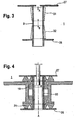
- FIG. 3 shows a part of a support member 1 with an adjustment for the restoring force, the sake of clarity, the rubber buffers and the connection part of the foot part 2 are not shown.
- the hardness of the rubber bearing is adjusted by the arrangement of a height-adjustable cone 31 on the pipe section 8.
- a further cone 32 fixed or also adjustable in height can be arranged on the pipe section 8.
- the lower cone 32 can perform an independent movement and / or a relative movement to the upper cone 31.
- rubber buffer are deformed, thereby changing the elastic properties of the return device with respect to the lateral deflection of the rubber bearing.
- FIG. 4 a further embodiment of the support member 1 is shown with the connecting device.
- both stop flanges 26 and 27 are fixed at a predetermined distance from each other.
- a deformation of the rubber pads 19 and 24 is accomplished here by means of a radial force on the rubber buffers 19 and 24.
- the radial distance of a wall piece 33 can be variably adjusted according to a desired adjustment of the hardness of the rubber bearing.
- the wall piece 33 may be formed, for example, in the form of two half-cylinders whose distance from each other is variable.
- FIG. 5a is another way to adjust the restoring force of the rubber bearing shown.
- the connecting device has hose clamps 34 and 35 which are arranged between the upper stop flange 26 and the connecting part 2 of the foot part and / or the lower stop flange 27 and the connecting part 2 of the foot part or the sliding disk 25.
- connection part 2 of the foot part such that its inner radius is adjustable in order to adjust the distance to the pipe section 8.
- the elastic element could be more or less compressed from the outside and so the restoring force can be adjusted.
- FIG. 5b One of the embodiments according to FIG. 5a used hose clamps 34 in section AA is in FIG. 5b shown.
- a dial 36 By turning a dial 36, the circumference of the press ring 37 of the hose clamp 34 can be changed. With a reduction in the circumference, the rubber bumpers 19 and / or 24 are squeezed inwardly, whereby the hardness of the rubber bearing can be adjusted in total.
- the hose clamps 34, 35 In order to still allow a pendulum motion, the hose clamps 34, 35 must be relatively flexible in the vertical direction.
- the hose clamps 34, 35 could also be formed flat and, for example, fitted in a groove 38 in the rubber buffers 19, 24, as in FIG FIG. 5c clarified. Since in this case there is sufficient freedom of movement between the connecting part 2 of the foot part and the fixed flange 26 for carrying out the oscillating movement, the flat-shaped hose clamp 34 can here consist of a relatively rigid material.
- a hose clamp on the outer region of the bow-shaped connecting part 2 of the foot part, provided that the one or more brackets are formed so that a radial displacement is possible.
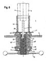
- FIG. 6 is a further embodiment of a support element 1 according to the invention also shown in the side view.
- the upper area with the standpipe construction up to the first annular disk 11 is identical.
- an external thread 15 is also provided here, on which a wing nut 16 is screwed. Also, a second annular disc 17 is pushed onto the pipe section 8 and is located on the top of the wing nut 16.
- a flange-shaped, one-piece rubber buffer 19 ' is provided which has a tapered annular groove 20 at the top and bottom and an external annular groove 22 in the knee region 21.
- a sliding disk 25 is provided between the rubber buffer 19 'and the foot part 2 in order to distribute the pressure support of the narrow underside of the foot part 2 over a larger area.
- the rubber buffer 19 ' is formed symmetrically and is thus on the lower side in the region of the sliding disk 25 and the annular disc 17 in its shape identical to the upper side.
- the rubber buffer 19 ' is also substantially annular here in order to encompass the pipe section 8.
- the outwardly extending flanges engage between the upper ring disk 11 and the connecting part 2 of the foot part or between the sliding disk 25 and the lower annular disk 17.
- the connection part 2 of the foot part is clamped in this way between the flanges.
- the effects and functions of this rubber buffer 19 ' essentially correspond to those of the rubber bumpers 19, 24 FIG. 1 ,
- the rubber buffer 19 ' is easily replaceable or retrofitted. There is only contact via the rubber buffer 19 'between the seat part and the foot part.
- the support element 1 also absorbs both vertical and oscillating movements of the user.
- the sleeve part 19 “may, for reasons of ease of installation, have longitudinal slots of suitable length and width.
- the embodiment of the support element of FIG. 7 corresponds to the shape of the rubber buffer 19 'of the embodiment of the FIG. 6 ,
- this one-piece rubber element 19 ' is provided in the region between the connecting part 2 and the pipe section 8, an additional recess of the one-piece rubber buffer 19'. All effects on the user and the setting possibilities of the restoring forces correspond substantially to the previous embodiments.
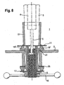
- the embodiment of the support element 1 of FIG. 8 also corresponds to the shape of the rubber buffer 19 'of the embodiment of the FIG. 6 ,
- this one-piece rubber buffer 19 ' is in the area between the connecting part 2 and the pipe section 8 only one, from the knee region 21 to the sliding plate 25 extending eggbubble of the one-piece rubber buffer 19' is provided. All effects on the user and the setting possibilities of the restoring forces correspond substantially to the previous embodiments.
Claims (18)
- Elément de support (1) pour une chaise, en particulier pour une chaise de bureau, dans lequel la chaise possède une partie d'assise avec un élément de raccordement (3), et l'élément de support (1) comprends une partie de pied, dans laquelle*
ladite partie de pied est maintenu pivotant et être remis à zéro à l'élément de raccordement (3) par l'intermédiaire d'un élément de rappel élastique (19, 19', 24), caractérisé en ce que ladite partie de pied comprend une partie de raccordement (2) qui est au moins partiellement entouré par ledit élément de rappel élastique (19, 19', 24) afin de maintenir ladite partie de pied au niveau dudit élément de raccordement (3), dans lequel
ledit élément de rappel élastique (19, 19', 24) est disposé entre un élément de butée supérieure (11) et ladite partie de raccordement (2) de ladite partie de pied et entre un élément de butée inférieur (17) et ladite partie de raccordement (2) de ladite partie de pied. - Elément de support (1) selon la revendication 1, caractérisé en ce que ledit élément de rappel élastique (19, 19', 24) est conçu de façon que ladite partie de raccordement (2) de ladite partie de pied peut être bloquée par l'élément de rappel élastique (19, 19', 24).
- Elément de support (1) selon la revendication 1, caractérisé en ce que lesdits éléments de butée (11, 17) sont fixés à ladite partie de raccordement (3) de ladite partie d'assise.
- Elément de support (1) selon l'une quelconque des revendications précédentes, caractérisé en ce que ledit élément de raccordement (3) de la partie d'assise est réalisé sous la forme d'un tube vertical s'étendant vers le bas.
- Elément de support (1) selon l'une quelconque des revendications précédentes, caractérisé en ce que ladite partie de raccordement (2) de ladite partie de pied est en contact avec le côté extérieur dudit élément de rappel élastique (19, 19', 24).
- Elément de support (1) selon l'une quelconque des revendications précédentes, caractérisé en ce que ledit élément de rappel élastique (19, 19', 24) comprend au moins deux brides s'étendant vers l'extérieur entre lesquels la pièce de raccordement (2) de la partie de pied est disposée.
- Elément de support (1) selon l'une quelconque des revendications précédentes, caractérisé en ce que ledit élément de rappel élastique (19, 19', 24) comprend au moins deux parties distinctes qui sont conçus coudées, respectivement, et dans lequel la partie de raccordement (2) de ladite partie de pied est montée contre les cavités coudées.
- Elément de support (1) selon l'une quelconque des revendications précédentes, caractérisé en ce que ledit élément de rappel élastique (19, 19', 24) comprend au moins un tampon de caoutchouc.
- Elément de support (1) selon l'une quelconque des revendications précédentes, caractérisé en ce que ledit élément de rappel élastique (19, 19', 24) est constitué par au moins un élastomère, polyuréthane ou caoutchouc naturel.
- Elément de support (1) selon l'une quelconque des revendications précédentes, caractérisé en ce que ledit élément de rappel élastique (19, 19', 24) comprend des cavités dans le matériau et/ou des cavités au niveau des surfaces de contact entre les éléments adjacents pour permettre un changement de forme de l'élément élastique (19, 19', 24).
- Elément de support, (1) selon l'une quelconque des revendications précédentes, caractérisé en ce que ledit élément de support (1) comporte des moyens de réglage et pour faire modifier la force de rappel de l'élément de rappel élastique (19, 19', 24).
- Elément de support (1) selon l'une quelconque des revendications précédentes, caractérisé en ce que ledit élément de support (1) comprend un moyen d'actionnement pour le réglage et pour modifier la force de rappel élastique de l'élément de rappel élastique (19, 19', 24).
- Elément de support (1) selon l'une quelconque des revendications précédentes 11 ou 12, caractérisé en ce que lesdits moyens sont conçus pour faire modifier la distance entre ledit élément de butée supérieur (11) et ledit élément de butée inférieur (17).
- Elément de support (1) selon l'une quelconque des revendications précédentes 11 ou 12, caractérisé en ce que lesdits moyens pour faire modifier la distance sont disposés entre la partie de raccordement (2) de la partie de pied et l'élément de raccordement (3, 33) de la partie d'assise.
- Elément de support (1) selon l'une quelconque des revendications précédentes 12 ou 15, caractérisé en ce que lesdits moyens pour comprimer l'élément de rappel élastique (19, 19', 24) sont formées à partir de l'extérieur.
- Elément de support (1) selon l'une quelconque des revendications précédentes 1 à 6 ou 8 à 15, caractérisé en ce que ledit élément de rappel élastique (19') est intégralement formé comme un douille ayant des épaulements d'appui ses deux extrémités et la partie de raccordement (2) de la partie de pied est s'ajuster contre la cavité entre lesdits épaulements.
- Chaise, particulièrement chaise de bureau, comprenant une partie d'assise et une partie de pied, caractérisé en ce que ladite partie d'assise comporte un élément de support (1) selon l'une quelconque des revendications précédentes.
- Chaise selon la revendication 17, caractérisé en ce que ladite chaise comprend un ressort à pression de gaz réglable en hauteur (4) qui est reliée à la partie d'assise.
Applications Claiming Priority (3)
| Application Number | Priority Date | Filing Date | Title |
|---|---|---|---|
| DE102005005089A DE102005005089A1 (de) | 2005-02-03 | 2005-02-03 | Tragelement für ein Sitzmöbel |
| DE200520001741 DE202005001741U1 (de) | 2005-02-03 | 2005-02-03 | Tragelement für ein Sitzmöbel |
| PCT/EP2006/000969 WO2006082083A1 (fr) | 2005-02-03 | 2006-02-03 | Element de support pour siege |
Publications (3)
| Publication Number | Publication Date |
|---|---|
| EP1845822A1 EP1845822A1 (fr) | 2007-10-24 |
| EP1845822B1 true EP1845822B1 (fr) | 2013-11-20 |
| EP1845822B2 EP1845822B2 (fr) | 2017-06-28 |
Family
ID=36294749
Family Applications (1)
| Application Number | Title | Priority Date | Filing Date |
|---|---|---|---|
| EP06706631.6A Active EP1845822B2 (fr) | 2005-02-03 | 2006-02-03 | Element de support pour siege |
Country Status (7)
| Country | Link |
|---|---|
| US (1) | US8075056B2 (fr) |
| EP (1) | EP1845822B2 (fr) |
| JP (1) | JP4956444B2 (fr) |
| CN (1) | CN101137308B (fr) |
| DE (2) | DE202005001741U1 (fr) |
| DK (1) | DK1845822T3 (fr) |
| WO (1) | WO2006082083A1 (fr) |
Families Citing this family (33)
| Publication number | Priority date | Publication date | Assignee | Title |
|---|---|---|---|---|
| DE202007011750U1 (de) * | 2007-08-22 | 2007-11-22 | GLÖCKL, Josef | Pendel-Hocker |
| NO328660B1 (no) * | 2008-04-02 | 2010-04-19 | Sapdesign As | Anordning ved stol |
| DE202008017086U1 (de) | 2008-12-24 | 2009-03-05 | Fritz Becker Kg | Bewegungsstuhl |
| CN102763235B (zh) | 2010-02-25 | 2015-06-24 | 默克专利股份有限公司 | 用于有机电子器件的电极处理方法 |
| US20130161602A1 (en) | 2010-06-24 | 2013-06-27 | Merck Patent Gesellschaft Mit Beschrankter Haftung | Process for modifying electrodes in an organic electronic device |
| KR20140035312A (ko) * | 2010-11-25 | 2014-03-21 | 코어체어 인코퍼레이티드 | 저항성 지지 기구 |
| CN102119816B (zh) * | 2011-03-28 | 2012-09-05 | 浙江永艺家具股份有限公司 | 一种转椅底盘 |
| CN102125360B (zh) * | 2011-03-28 | 2012-11-14 | 浙江永艺家具股份有限公司 | 一种橡胶弹簧 |
| US9060612B2 (en) | 2011-05-17 | 2015-06-23 | Rebecca M. Lee | Balance chair |
| DE102013102034B4 (de) * | 2012-10-19 | 2014-10-30 | Josef Glöckl | Rückstellvorrichtung zum selbsttätigen Einstellen der Rückstellkraft |
| EP2721965B1 (fr) * | 2012-10-19 | 2015-05-06 | aeris GmbH | Meuble destiné à s'asseoir avec sécurité anti-rotation |
| DE102014000386A1 (de) | 2014-01-10 | 2015-07-16 | Eberhard Lenz | Bewegliches Sitzlager |
| WO2015104686A2 (fr) * | 2014-01-12 | 2015-07-16 | Inventor Group Gmbh | Tabouret inclinable |
| CN205795341U (zh) * | 2016-05-19 | 2016-12-14 | 强龙家具股份有限公司 | 一种双向控制气杆阀门的椅子 |
| CN109561763B (zh) | 2016-06-06 | 2021-06-15 | B&Z制作公司 | 气瓶快速释放装置 |
| JP6709475B2 (ja) * | 2016-08-18 | 2020-06-17 | 株式会社クオリ | 傾動可能なスツールまたはラウンジチェア |
| CN107836909A (zh) * | 2016-09-21 | 2018-03-27 | 杜家柯 | 一种硅胶连接弹簧的床垫及其制作方法 |
| US10034547B1 (en) * | 2017-03-03 | 2018-07-31 | Oasyschair Co., Ltd. | Reclinable office chair |
| CN109198950A (zh) * | 2017-06-29 | 2019-01-15 | 浙江恒林椅业股份有限公司 | 一种坐具 |
| WO2019133660A1 (fr) | 2017-12-27 | 2019-07-04 | Ergoair, Inc. | Support de siège pneumatique |
| US20210204702A1 (en) * | 2018-07-12 | 2021-07-08 | Corechair Incorporated | Resistive support mechanism |
| HUP1800441A1 (hu) * | 2018-12-21 | 2020-06-29 | Ferenc Benesch | Aktív szék, elsõsorban irodai használatra |
| US11045002B1 (en) | 2019-01-23 | 2021-06-29 | B&Z Productions, LLC | Quick-release footrest device |
| US20220240681A1 (en) * | 2019-06-10 | 2022-08-04 | Inventor Group Gmbh | Tiltable Stool |
| CN110367724A (zh) * | 2019-06-20 | 2019-10-25 | 扬州市高升机械有限公司 | 一种便移式多维缓冲减震座椅 |
| DE102020007990A1 (de) | 2020-02-14 | 2021-08-19 | Hellstern medical GmbH | Operationsstuhl |
| DE102020103861B3 (de) | 2020-02-14 | 2021-04-29 | Hellstern medical GmbH | Operationsstuhl |
| DE102020116642A1 (de) * | 2020-06-24 | 2021-12-30 | Aeris Gmbh | Stuhl bzw. ein Gelenksystem für einen Stuhl oder eine Sitzvorrichtung |
| US11533999B2 (en) | 2020-07-30 | 2022-12-27 | B&Z Productions, LLC | Seat plate gas cylinder quick-release device |
| KR102275811B1 (ko) | 2020-10-23 | 2021-07-09 | 체어마이스터 주식회사 | 경동 의자 |
| KR102267652B1 (ko) * | 2020-12-04 | 2021-06-22 | (주)퍼맥스 | 의자용 다리 |
| CN112849944A (zh) * | 2021-01-06 | 2021-05-28 | 邻家家居(广州)装饰材料有限公司 | 一种链条装配流水线 |
| DE102021110612A1 (de) | 2021-04-26 | 2022-10-27 | Aeris Gmbh | Aktivdynamisches Sitzmöbel |
Family Cites Families (13)
| Publication number | Priority date | Publication date | Assignee | Title |
|---|---|---|---|---|
| US1619069A (en) * | 1924-08-06 | 1927-03-01 | Marquette Tool & Mfg Co | Blank-holding means |
| US1930021A (en) * | 1932-11-30 | 1933-10-10 | Gen Fireproofing Co | Chair |
| FR1170615A (fr) * | 1957-04-04 | 1959-01-16 | Tabouret d'opérateur plus spécialement pour dentistes | |
| FR1344062A (fr) * | 1962-01-17 | 1963-11-22 | Bishop & Babcock Corp | Support isolant de fixation d'un élément sur un panneau perforé, notamment d'une caisse de voiture automobile sur le châssis |
| US3193237A (en) * | 1962-04-23 | 1965-07-06 | Bishop And Babock Corp | Body mounting fastener for automobiles |
| FR1341308A (fr) | 1962-12-18 | 1963-10-25 | Nu Parq Products Ltd | Tabouret ou siège analogue de construction perfectionnée |
| US3304043A (en) * | 1965-03-02 | 1967-02-14 | Lord Corp | Resilient mounting |
| US4858880A (en) * | 1987-05-29 | 1989-08-22 | Caterpillar Inc. | Resilient load supporting and motion accommodating mounting apparatus |
| CH678388A5 (fr) † | 1989-04-25 | 1991-09-13 | Hugo Degen | |
| DE29709558U1 (de) | 1997-06-02 | 1997-09-18 | Gloeckl Josef | Barhocker |
| US6601818B1 (en) * | 2000-10-12 | 2003-08-05 | Lord Corporation | Tilting mount with integral flange |
| CN2590457Y (zh) * | 2002-12-11 | 2003-12-10 | 李培章 | 一种倒立健身椅 |
| US7547067B2 (en) * | 2004-12-01 | 2009-06-16 | Keilhauer (Partnership) | Tilt and swivel chair and mechanism therefor |
-
2005
- 2005-02-03 DE DE200520001741 patent/DE202005001741U1/de not_active Expired - Lifetime
- 2005-02-03 DE DE102005005089A patent/DE102005005089A1/de not_active Ceased
-
2006
- 2006-02-03 DK DK06706631.6T patent/DK1845822T3/da active
- 2006-02-03 JP JP2007553546A patent/JP4956444B2/ja not_active Expired - Fee Related
- 2006-02-03 WO PCT/EP2006/000969 patent/WO2006082083A1/fr active Application Filing
- 2006-02-03 CN CN2006800072130A patent/CN101137308B/zh active Active
- 2006-02-03 EP EP06706631.6A patent/EP1845822B2/fr active Active
- 2006-02-03 US US11/883,139 patent/US8075056B2/en active Active
Also Published As
| Publication number | Publication date |
|---|---|
| US20080143162A1 (en) | 2008-06-19 |
| CN101137308B (zh) | 2011-12-28 |
| WO2006082083A1 (fr) | 2006-08-10 |
| EP1845822A1 (fr) | 2007-10-24 |
| JP4956444B2 (ja) | 2012-06-20 |
| EP1845822B2 (fr) | 2017-06-28 |
| DE202005001741U1 (de) | 2005-03-31 |
| DK1845822T3 (da) | 2014-02-10 |
| DE102005005089A1 (de) | 2006-08-10 |
| JP2008531075A (ja) | 2008-08-14 |
| US8075056B2 (en) | 2011-12-13 |
| WO2006082083A9 (fr) | 2007-09-20 |
| CN101137308A (zh) | 2008-03-05 |
Similar Documents
| Publication | Publication Date | Title |
|---|---|---|
| EP1845822B1 (fr) | Element de support pour siege | |
| EP0586675B1 (fr) | Siege dynamico-actif | |
| EP1712411B1 (fr) | Siège de véhicule à dossier deformable en forme de S | |
| EP2427081B1 (fr) | Meuble pour s'asseoir roulant muni d'un dispositif de commande d'une force de rappel | |
| EP2985177B1 (fr) | Siege de vehicule dote d'une forme de dossier pouvant etre modifiee | |
| EP1265513A1 (fr) | Systeme d'assise et de dossier pour des sieges, notamment pour des chaises de bureau | |
| DE102010016989B4 (de) | Kippvorrichtung zum Neigen einer Fläche, insbesondere einer Sitzfläche und Stuhl mit einer solchen Kippvorrichtung | |
| DE102006021439A1 (de) | Stuhl, insbesondere Bürostuhl und Gelenkvorrichtung für einen Stuhl | |
| DE102007041520B3 (de) | Kopfstütze für ein Fahrzeug | |
| WO2019137958A1 (fr) | Chaise munie d'une articulation auto-ajustable | |
| EP2862482A1 (fr) | Dispositif de suspension et d'oscillation | |
| DE10135473B4 (de) | Sitz, insbesondere für Automobile | |
| DE202005013019U1 (de) | Unterfederung von Sitz- oder Liegemöbeln | |
| DE202012104761U1 (de) | Rückenlehnenanordnung | |
| EP2689692B1 (fr) | Meuble d'assise, en particulier chaise de bureau | |
| EP2180810A1 (fr) | Tabouret à suspension | |
| EP3626127A1 (fr) | Chaise dotée d'un dispositif d'articulation et dispositif d'articulation | |
| EP2721960B1 (fr) | Meuble siège, en particulier chaise de bureau rotative | |
| EP4081072B1 (fr) | Chaise et système de joint pour une chaise ou un appareil d'assise | |
| DE102018120253A1 (de) | Sitzmöbel mit unter dem Sitzteil angeordneter Spiralfeder und Schwenkbereichsbegrenzungsanordnung | |
| DE102009038319B4 (de) | Stuhl | |
| EP0995375B1 (fr) | Appui-tête/nuque | |
| WO2010028411A1 (fr) | Dispositif de soutien pour la région lombaire | |
| EP3434147A2 (fr) | Siège de chaise et chaise | |
| CH714262B1 (de) | Aktiv-dynamische Sitzvorrichtung. |
Legal Events
| Date | Code | Title | Description |
|---|---|---|---|
| PUAI | Public reference made under article 153(3) epc to a published international application that has entered the european phase |
Free format text: ORIGINAL CODE: 0009012 |
|
| 17P | Request for examination filed |
Effective date: 20070829 |
|
| AK | Designated contracting states |
Kind code of ref document: A1 Designated state(s): AT BE BG CH CY CZ DE DK EE ES FI FR GB GR HU IE IS IT LI LT LU LV MC NL PL PT RO SE SI SK TR |
|
| 17Q | First examination report despatched |
Effective date: 20071227 |
|
| DAX | Request for extension of the european patent (deleted) | ||
| GRAP | Despatch of communication of intention to grant a patent |
Free format text: ORIGINAL CODE: EPIDOSNIGR1 |
|
| GRAP | Despatch of communication of intention to grant a patent |
Free format text: ORIGINAL CODE: EPIDOSNIGR1 |
|
| INTG | Intention to grant announced |
Effective date: 20130809 |
|
| GRAS | Grant fee paid |
Free format text: ORIGINAL CODE: EPIDOSNIGR3 |
|
| GRAA | (expected) grant |
Free format text: ORIGINAL CODE: 0009210 |
|
| AK | Designated contracting states |
Kind code of ref document: B1 Designated state(s): AT BE BG CH CY CZ DE DK EE ES FI FR GB GR HU IE IS IT LI LT LU LV MC NL PL PT RO SE SI SK TR |
|
| REG | Reference to a national code |
Ref country code: GB Ref legal event code: FG4D Free format text: NOT ENGLISH |
|
| REG | Reference to a national code |
Ref country code: CH Ref legal event code: EP |
|
| REG | Reference to a national code |
Ref country code: AT Ref legal event code: REF Ref document number: 641066 Country of ref document: AT Kind code of ref document: T Effective date: 20131215 |
|
| REG | Reference to a national code |
Ref country code: IE Ref legal event code: FG4D Free format text: LANGUAGE OF EP DOCUMENT: GERMAN |
|
| REG | Reference to a national code |
Ref country code: DE Ref legal event code: R096 Ref document number: 502006013364 Country of ref document: DE Effective date: 20140109 |
|
| REG | Reference to a national code |
Ref country code: CH Ref legal event code: NV Representative=s name: KELLER AND PARTNER PATENTANWAELTE AG, CH |
|
| REG | Reference to a national code |
Ref country code: DK Ref legal event code: T3 Effective date: 20140203 |
|
| REG | Reference to a national code |
Ref country code: NL Ref legal event code: VDEP Effective date: 20131120 |
|
| REG | Reference to a national code |
Ref country code: LT Ref legal event code: MG4D |
|
| PG25 | Lapsed in a contracting state [announced via postgrant information from national office to epo] |
Ref country code: SE Free format text: LAPSE BECAUSE OF FAILURE TO SUBMIT A TRANSLATION OF THE DESCRIPTION OR TO PAY THE FEE WITHIN THE PRESCRIBED TIME-LIMIT Effective date: 20131120 Ref country code: LT Free format text: LAPSE BECAUSE OF FAILURE TO SUBMIT A TRANSLATION OF THE DESCRIPTION OR TO PAY THE FEE WITHIN THE PRESCRIBED TIME-LIMIT Effective date: 20131120 Ref country code: NL Free format text: LAPSE BECAUSE OF FAILURE TO SUBMIT A TRANSLATION OF THE DESCRIPTION OR TO PAY THE FEE WITHIN THE PRESCRIBED TIME-LIMIT Effective date: 20131120 Ref country code: IS Free format text: LAPSE BECAUSE OF FAILURE TO SUBMIT A TRANSLATION OF THE DESCRIPTION OR TO PAY THE FEE WITHIN THE PRESCRIBED TIME-LIMIT Effective date: 20140320 |
|
| PGFP | Annual fee paid to national office [announced via postgrant information from national office to epo] |
Ref country code: NL Payment date: 20140218 Year of fee payment: 9 Ref country code: FI Payment date: 20140212 Year of fee payment: 9 Ref country code: DK Payment date: 20140218 Year of fee payment: 9 |
|
| REG | Reference to a national code |
Ref country code: NL Ref legal event code: T3 |
|
| PG25 | Lapsed in a contracting state [announced via postgrant information from national office to epo] |
Ref country code: ES Free format text: LAPSE BECAUSE OF FAILURE TO SUBMIT A TRANSLATION OF THE DESCRIPTION OR TO PAY THE FEE WITHIN THE PRESCRIBED TIME-LIMIT Effective date: 20131120 Ref country code: LV Free format text: LAPSE BECAUSE OF FAILURE TO SUBMIT A TRANSLATION OF THE DESCRIPTION OR TO PAY THE FEE WITHIN THE PRESCRIBED TIME-LIMIT Effective date: 20131120 |
|
| PGFP | Annual fee paid to national office [announced via postgrant information from national office to epo] |
Ref country code: AT Payment date: 20140212 Year of fee payment: 9 |
|
| REG | Reference to a national code |
Ref country code: SE Ref legal event code: TRGR Ref country code: SE Ref legal event code: RINS Effective date: 20140526 |
|
| PG25 | Lapsed in a contracting state [announced via postgrant information from national office to epo] |
Ref country code: PT Free format text: LAPSE BECAUSE OF FAILURE TO SUBMIT A TRANSLATION OF THE DESCRIPTION OR TO PAY THE FEE WITHIN THE PRESCRIBED TIME-LIMIT Effective date: 20140320 |
|
| PG25 | Lapsed in a contracting state [announced via postgrant information from national office to epo] |
Ref country code: EE Free format text: LAPSE BECAUSE OF FAILURE TO SUBMIT A TRANSLATION OF THE DESCRIPTION OR TO PAY THE FEE WITHIN THE PRESCRIBED TIME-LIMIT Effective date: 20131120 |
|
| REG | Reference to a national code |
Ref country code: DE Ref legal event code: R026 Ref document number: 502006013364 Country of ref document: DE |
|
| PLBI | Opposition filed |
Free format text: ORIGINAL CODE: 0009260 |
|
| PG25 | Lapsed in a contracting state [announced via postgrant information from national office to epo] |
Ref country code: RO Free format text: LAPSE BECAUSE OF FAILURE TO SUBMIT A TRANSLATION OF THE DESCRIPTION OR TO PAY THE FEE WITHIN THE PRESCRIBED TIME-LIMIT Effective date: 20131120 Ref country code: SK Free format text: LAPSE BECAUSE OF FAILURE TO SUBMIT A TRANSLATION OF THE DESCRIPTION OR TO PAY THE FEE WITHIN THE PRESCRIBED TIME-LIMIT Effective date: 20131120 Ref country code: CZ Free format text: LAPSE BECAUSE OF FAILURE TO SUBMIT A TRANSLATION OF THE DESCRIPTION OR TO PAY THE FEE WITHIN THE PRESCRIBED TIME-LIMIT Effective date: 20131120 Ref country code: PL Free format text: LAPSE BECAUSE OF FAILURE TO SUBMIT A TRANSLATION OF THE DESCRIPTION OR TO PAY THE FEE WITHIN THE PRESCRIBED TIME-LIMIT Effective date: 20131120 |
|
| BERE | Be: lapsed |
Owner name: GLOCKL, JOSEF Effective date: 20140228 |
|
| 26 | Opposition filed |
Opponent name: GIRSBERGER HOLDING AG Effective date: 20140820 |
|
| PG25 | Lapsed in a contracting state [announced via postgrant information from national office to epo] |
Ref country code: LU Free format text: LAPSE BECAUSE OF FAILURE TO SUBMIT A TRANSLATION OF THE DESCRIPTION OR TO PAY THE FEE WITHIN THE PRESCRIBED TIME-LIMIT Effective date: 20140203 Ref country code: MC Free format text: LAPSE BECAUSE OF FAILURE TO SUBMIT A TRANSLATION OF THE DESCRIPTION OR TO PAY THE FEE WITHIN THE PRESCRIBED TIME-LIMIT Effective date: 20131120 |
|
| PLAX | Notice of opposition and request to file observation + time limit sent |
Free format text: ORIGINAL CODE: EPIDOSNOBS2 |
|
| REG | Reference to a national code |
Ref country code: DE Ref legal event code: R026 Ref document number: 502006013364 Country of ref document: DE Effective date: 20140820 |
|
| REG | Reference to a national code |
Ref country code: IE Ref legal event code: MM4A |
|
| PLBB | Reply of patent proprietor to notice(s) of opposition received |
Free format text: ORIGINAL CODE: EPIDOSNOBS3 |
|
| PG25 | Lapsed in a contracting state [announced via postgrant information from national office to epo] |
Ref country code: IE Free format text: LAPSE BECAUSE OF NON-PAYMENT OF DUE FEES Effective date: 20140203 Ref country code: BE Free format text: LAPSE BECAUSE OF NON-PAYMENT OF DUE FEES Effective date: 20140228 |
|
| PG25 | Lapsed in a contracting state [announced via postgrant information from national office to epo] |
Ref country code: SI Free format text: LAPSE BECAUSE OF FAILURE TO SUBMIT A TRANSLATION OF THE DESCRIPTION OR TO PAY THE FEE WITHIN THE PRESCRIBED TIME-LIMIT Effective date: 20131120 |
|
| PG25 | Lapsed in a contracting state [announced via postgrant information from national office to epo] |
Ref country code: IT Free format text: LAPSE BECAUSE OF FAILURE TO SUBMIT A TRANSLATION OF THE DESCRIPTION OR TO PAY THE FEE WITHIN THE PRESCRIBED TIME-LIMIT Effective date: 20131120 |
|
| REG | Reference to a national code |
Ref country code: CH Ref legal event code: PCAR Free format text: NEW ADDRESS: EIGERSTRASSE 2 POSTFACH, 3000 BERN 14 (CH) |
|
| PGRI | Patent reinstated in contracting state [announced from national office to epo] |
Ref country code: SE Effective date: 20140526 |
|
| REG | Reference to a national code |
Ref country code: NL Ref legal event code: V1 Effective date: 20150901 |
|
| REG | Reference to a national code |
Ref country code: DK Ref legal event code: EBP Effective date: 20150228 |
|
| PG25 | Lapsed in a contracting state [announced via postgrant information from national office to epo] |
Ref country code: NL Free format text: LAPSE BECAUSE OF FAILURE TO SUBMIT A TRANSLATION OF THE DESCRIPTION OR TO PAY THE FEE WITHIN THE PRESCRIBED TIME-LIMIT Effective date: 20150901 |
|
| REG | Reference to a national code |
Ref country code: AT Ref legal event code: MM01 Ref document number: 641066 Country of ref document: AT Kind code of ref document: T Effective date: 20150203 |
|
| PG25 | Lapsed in a contracting state [announced via postgrant information from national office to epo] |
Ref country code: FI Free format text: LAPSE BECAUSE OF NON-PAYMENT OF DUE FEES Effective date: 20150203 |
|
| PG25 | Lapsed in a contracting state [announced via postgrant information from national office to epo] |
Ref country code: AT Free format text: LAPSE BECAUSE OF NON-PAYMENT OF DUE FEES Effective date: 20150203 |
|
| PG25 | Lapsed in a contracting state [announced via postgrant information from national office to epo] |
Ref country code: DK Free format text: LAPSE BECAUSE OF NON-PAYMENT OF DUE FEES Effective date: 20150228 |
|
| REG | Reference to a national code |
Ref country code: FR Ref legal event code: PLFP Year of fee payment: 11 |
|
| PG25 | Lapsed in a contracting state [announced via postgrant information from national office to epo] |
Ref country code: BG Free format text: LAPSE BECAUSE OF FAILURE TO SUBMIT A TRANSLATION OF THE DESCRIPTION OR TO PAY THE FEE WITHIN THE PRESCRIBED TIME-LIMIT Effective date: 20131120 |
|
| PG25 | Lapsed in a contracting state [announced via postgrant information from national office to epo] |
Ref country code: CY Free format text: LAPSE BECAUSE OF FAILURE TO SUBMIT A TRANSLATION OF THE DESCRIPTION OR TO PAY THE FEE WITHIN THE PRESCRIBED TIME-LIMIT Effective date: 20131120 Ref country code: GR Free format text: LAPSE BECAUSE OF FAILURE TO SUBMIT A TRANSLATION OF THE DESCRIPTION OR TO PAY THE FEE WITHIN THE PRESCRIBED TIME-LIMIT Effective date: 20140221 |
|
| PG25 | Lapsed in a contracting state [announced via postgrant information from national office to epo] |
Ref country code: HU Free format text: LAPSE BECAUSE OF FAILURE TO SUBMIT A TRANSLATION OF THE DESCRIPTION OR TO PAY THE FEE WITHIN THE PRESCRIBED TIME-LIMIT; INVALID AB INITIO Effective date: 20060203 Ref country code: TR Free format text: LAPSE BECAUSE OF FAILURE TO SUBMIT A TRANSLATION OF THE DESCRIPTION OR TO PAY THE FEE WITHIN THE PRESCRIBED TIME-LIMIT Effective date: 20131120 |
|
| REG | Reference to a national code |
Ref country code: FR Ref legal event code: PLFP Year of fee payment: 12 |
|
| PUAH | Patent maintained in amended form |
Free format text: ORIGINAL CODE: 0009272 |
|
| STAA | Information on the status of an ep patent application or granted ep patent |
Free format text: STATUS: PATENT MAINTAINED AS AMENDED |
|
| 27A | Patent maintained in amended form |
Effective date: 20170628 |
|
| AK | Designated contracting states |
Kind code of ref document: B2 Designated state(s): AT BE BG CH CY CZ DE DK EE ES FI FR GB GR HU IE IS IT LI LT LU LV MC NL PL PT RO SE SI SK TR |
|
| REG | Reference to a national code |
Ref country code: DE Ref legal event code: R102 Ref document number: 502006013364 Country of ref document: DE |
|
| REG | Reference to a national code |
Ref country code: CH Ref legal event code: AELC |
|
| REG | Reference to a national code |
Ref country code: SE Ref legal event code: RPEO |
|
| REG | Reference to a national code |
Ref country code: FR Ref legal event code: PLFP Year of fee payment: 13 |
|
| REG | Reference to a national code |
Ref country code: CH Ref legal event code: PFA Owner name: GLOECKL, JOSEF, DE Free format text: FORMER OWNER: GLOECKL, JOSEF, DE |
|
| PGFP | Annual fee paid to national office [announced via postgrant information from national office to epo] |
Ref country code: SE Payment date: 20210217 Year of fee payment: 16 |
|
| REG | Reference to a national code |
Ref country code: DE Ref legal event code: R082 Ref document number: 502006013364 Country of ref document: DE Representative=s name: PATENTANWAELTE STAEGER & SPERLING PARTNERSCHAF, DE Ref country code: DE Ref legal event code: R081 Ref document number: 502006013364 Country of ref document: DE Owner name: AERIS GMBH, DE Free format text: FORMER OWNER: GLOECKL, JOSEF, 85551 KIRCHHEIM, DE |
|
| REG | Reference to a national code |
Ref country code: SE Ref legal event code: EUG |
|
| PG25 | Lapsed in a contracting state [announced via postgrant information from national office to epo] |
Ref country code: SE Free format text: LAPSE BECAUSE OF FAILURE TO SUBMIT A TRANSLATION OF THE DESCRIPTION OR TO PAY THE FEE WITHIN THE PRESCRIBED TIME-LIMIT Effective date: 20220204 |
|
| REG | Reference to a national code |
Ref country code: GB Ref legal event code: 732E Free format text: REGISTERED BETWEEN 20221020 AND 20221026 |
|
| PGFP | Annual fee paid to national office [announced via postgrant information from national office to epo] |
Ref country code: FR Payment date: 20230220 Year of fee payment: 18 Ref country code: CH Payment date: 20230307 Year of fee payment: 18 |
|
| PGFP | Annual fee paid to national office [announced via postgrant information from national office to epo] |
Ref country code: GB Payment date: 20230220 Year of fee payment: 18 |
|
| PGFP | Annual fee paid to national office [announced via postgrant information from national office to epo] |
Ref country code: DE Payment date: 20240219 Year of fee payment: 19 |