EP1844975B1 - Sitzdrehvorrichtung für ein Fahrzeug - Google Patents
Sitzdrehvorrichtung für ein Fahrzeug Download PDFInfo
- Publication number
- EP1844975B1 EP1844975B1 EP07105951A EP07105951A EP1844975B1 EP 1844975 B1 EP1844975 B1 EP 1844975B1 EP 07105951 A EP07105951 A EP 07105951A EP 07105951 A EP07105951 A EP 07105951A EP 1844975 B1 EP1844975 B1 EP 1844975B1
- Authority
- EP
- European Patent Office
- Prior art keywords
- swing lever
- locating lug
- movable base
- recessed portion
- swiveling device
- Prior art date
- Legal status (The legal status is an assumption and is not a legal conclusion. Google has not performed a legal analysis and makes no representation as to the accuracy of the status listed.)
- Active
Links
- 230000000295 complement effect Effects 0.000 claims description 3
- 230000002787 reinforcement Effects 0.000 description 2
- 238000005452 bending Methods 0.000 description 1
- 230000000694 effects Effects 0.000 description 1
- 239000002184 metal Substances 0.000 description 1
Images

Classifications
-
- B—PERFORMING OPERATIONS; TRANSPORTING
- B60—VEHICLES IN GENERAL
- B60N—SEATS SPECIALLY ADAPTED FOR VEHICLES; VEHICLE PASSENGER ACCOMMODATION NOT OTHERWISE PROVIDED FOR
- B60N2/00—Seats specially adapted for vehicles; Arrangement or mounting of seats in vehicles
- B60N2/02—Seats specially adapted for vehicles; Arrangement or mounting of seats in vehicles the seat or part thereof being movable, e.g. adjustable
- B60N2/04—Seats specially adapted for vehicles; Arrangement or mounting of seats in vehicles the seat or part thereof being movable, e.g. adjustable the whole seat being movable
- B60N2/14—Seats specially adapted for vehicles; Arrangement or mounting of seats in vehicles the seat or part thereof being movable, e.g. adjustable the whole seat being movable rotatable, e.g. to permit easy access
- B60N2/146—Seats specially adapted for vehicles; Arrangement or mounting of seats in vehicles the seat or part thereof being movable, e.g. adjustable the whole seat being movable rotatable, e.g. to permit easy access characterised by the locking device
Definitions
- the present invention relates to a device for swiveling a vehicle seat in a horizontal plane.
- the seat swiveling device for use in a vehicle is disclosed in Japanese Utility Model Application Publication No. 5-56582 and the Japanese Unexamined Patent Application Publication No. 10-109575 .
- the latter shows a mechanism for adjusting the swiveling of the vehicle seat as a seat swiveling device for a vehicle.
- Such an adjusting mechanism includes a lower base which is fixed to the floor of a vehicle compartment and has an annular support portion, an upper base which is slidably and pivotably mounted on the annular support portion of the lower base and has at its center an opening for fixing therein a vehicle seat assembly, and a holder which holds the upper base in such a way that the upper base is slidable relative to the annular support portion of the lower base.
- the holder has a cylindrical portion having formed therethrough plural holes which are arranged circumferentially in the cylindrical portion at a predetermined spaced intervals.
- a lock plate is pivotably mounted to the upper base by a pivot shaft. The lock plate has plural teeth which are engageable with holes in the holder.
- the lock plate performs the function of making the upper base rotatable relative to the lower base or locked to the lower base so that the upper base is unrotatable relative to the lower base.
- the lock plate is mounted to the lower base by and pivoted about the pivot shaft which is provided on the lower base and has a circular cross section.
- the lock plate has formed therein a shaft hole of a shape of a perfect circle having substantially the same diameter as the pivot shaft.
- the teeth are moved along a path of an arc centered on the pivot shaft.
- the teeth are formed in a direction that is substantially the same as the direction tangential to the above path of an arc, and the distance between the center of the pivot shaft and the lateral sides of the engaging teeth is constant.
- the shaft hole in the lock plate is of a perfect circle whose diameter corresponds to the diameter of the pivot shaft, and the distance between the center of the pivot shaft and the lateral sides of the teeth is constant. Therefore, the teeth tend to be engaged with the hole such that only one lateral side of the teeth contacts with one lateral side of the hole.
- the shape of the hole has to correspond exactly to the shape of the teeth and the teeth and their holes have to be precisely positioned relative to each other.
- the teeth and the hole need to be formed with high accuracy and the teeth need to be accurately positioned with respect to the teeth in turning the vehicle seat assembly.
- the engaging of the teeth of the swing lever cannot be brought into snug contact with the hole of the upper base with no gap therebetween by relatively easy operation.
- an object of the present invention is to provide a seat swiveling device in a vehicle which brings the teeth or a locating lug of the swing lever into contact with the hole of the upper base or a movable base with no gap therebetween while permitting relatively easy operation for the engagement.
- a seat swiveling device of a vehicle has a vehicle body.
- the seat swiveling device comprises a stationary base secured to the vehicle body, a movable base connected to the stationary base through a first pivot shaft, a vehicle seat assembly mounted on a top face of the movable base and a swing lever changing locking and unlocking positions of the movable base relative to the stationary base.
- the movable base has a second pivot shaft for supporting the swing lever so that the swing lever is pivoted.
- the stationary base has a guide hole for defining a range in which the movable base is pivotable.
- the swing lever has an elongated hole in which the second pivot shaft is inserted and a locating lug which is guided along the guide hole.
- the guide hole has a recessed portion with which the locating lug is engaged by pivoting the swing lever thereby to fix the movable base to the stationary base at a predetermined position.
- the swing lever is movable relative to the second pivot shaft in accordance with the shape of the elongated hole.
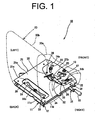
- FIG. 1 is a perspective view showing the seat swiveling device according to the preferred embodiment of the present invention.
- the seat swiveling device 10 for a vehicle has a stationary base 11 which is secured to the vehicle body and a movable base 21 which is held to the top face of the stationary base 11 by a pivot shaft 13 for pivoting about the pivot shaft 13 relative to the stationary base 11.
- a vehicle seat assembly 20 is mounted on the top face of the movable base 21 so that the vehicle seat assembly 20 is swiveled or oriented in different directions as the movable base 21 is pivoted in a horizontal plane about the pivot shaft 13.
- the vehicle seat assembly 20 for a vehicle operator includes a seat 20a and a backrest 20b.
- the movable base 21 has a swing lever 31 that is operated by the operator on the vehicle seat assembly 20 for changing the movable base 21 between its locked and unlocked positions relative to the stationary base 11.
- the seat swiveling device of the vehicle 10 changes the direction of the vehicle seat assembly 20 by the operation of the swing lever 31 by the operator.
- the stationary base 11 is made of a bent metal plate having punched holes.
- the stationary base 11 has contact portions 11a and 11b which are formed by bending the opposite lateral end portions of the stationary base 11 along the longitudinal direction thereof.
- Fixing members 12 are provided in the front and rear portions of each of the contact portions 11a and 11b for fixing the stationary base 11 to the vehicle body.
- the stationary base 11 has a horizontal portion 11c which is formed between the opposite contact portions 11a and 11b.
- the horizontal portion 11c is slightly raised from the contact portions 11a and 11b, and the top face of the horizontal portion 11c is flat.
- the pivot shaft 13 is provided upstanding at the center on the top face of the horizontal portion 11c adjacent to the front end thereof. The pivot shaft 13 pivotally holds the movable base 21 to function as a pivot for the movable base 21.
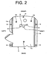
- Shafts 14a through 14c which are similar to the pivot shaft 13 are provided on the top face of the horizontal portion 11c. These shafts 14a through 14c are inserted in guide holes 22 through 24, respectively, which are formed in the movable base 21 as shown in FIG. 1 . As shown in FIG. 2 , the shaft 14a is provided adjacent to the contact portion 11a, the shaft 14b adjacent to the contact portion 11b and the shaft 14c adjacent to the rear edge of the horizontal portion 11c, respectively.
- a guide hole 15 is formed in the horizontal portion 11c of the stationary base 11 which defines the range in which the movable base 21 is pivotable.
- the guide hole 15 received therein a locating lug 34 of the swing lever 31 and has an arcuate portion 16 and recessed portions 17 and 18 engageable with the locating lug 34.
- the arcuate portion 16 is formed behind the pivot shaft 13 in the shape of a circular arc which is centered at the pivot shaft 13.
- the recessed portions 17 and 18 of the guide hole 15 extend rearwardly from predetermined positions of the arcuate portion 16.
- the arcuate portion 16 of the guide hole 15 limits the pivoting range of the movable base 21, that is about 17 degrees in clockwise direction and about 25 degrees in counter-clockwise direction from the center position (which will be described later) of the movable base 21 as viewed in plan view of FIG. 2 .
- the recessed portions 17 and 18 of the guide hole 15 are provided at the predetermined positions of the arcuate portion 16 in the form of cuts extending rearwardly.
- the recessed portions 17 and 18 of the preferred embodiment have the substantially same and complementary shape as the locating lug 34.
- the recessed portion 17 is provided at such a position that the movable base 21 is located at the aforementioned center position where the seat assembly 20 faces straightforward when the locating lug 34 is engaged with the recessed portion 17.
- the recessed portion 18 is provided at a position that is spaced by about 17 degrees in clockwise direction from the position of the recessed portion 18.
- the recessed portion 17 serves to hold the movable base 21 at the center position
- the recessed portion 18 serves to hold the movable base 21 at the position that is spaced by 17 degrees in clockwise direction from the center position.
- the recessed portions 17 and 18 are wedge-shaped so that the widths of the recessed portions 17 and 18 are narrowed rearwardly or toward the ends thereof. The engagement of the locating lug 34 with the recessed portions 17 and 18 causes the movable base 21 to be fixed to the stationary base 11.
- the movable base 21 is a plate-like member connected to the stationary base 11 through the pivot shaft 13.
- the movable base 21 of the preferred embodiment has a seat base portion 21 a on which the vehicle seat assembly 20 is to be mounted and lower portions 21b and 21c which are formed lower than the seat base portion 21a.
- the lower portions 21b, 21c are formed in the front and the rear of the movable base 21, respectively.
- a shaft hole for receiving therethrough the pivot shaft 13 (not shown in the drawings) and guide holes 22 and 23 through which the shafts 14a and 14b are inserted are formed in the front of the lower portion 21b (hereinafter referred to as "front lower portion") of the movable base 21.
- a guide hole 24 through which the shaft 14c at the rear of the movable base 21 is inserted is formed in an arc-shape in the rear of the lower portion 21c (hereinafter referred to as "rear lower portion") of the movable base 21.
- the guide holes 22 through 24 in the front lower portion 21b and rear lower portion 21c are formed in the shape of are of a circle whose center corresponds to the pivot shaft 13.
- the lengths of the guide hole 22 through 24 are determined in accordance with the length of the guide hole 15 in the stationary base 11 which defines the pivoting range of the movable base 21.
- retaining nuts are attached to the tops of the respective pivot shaft 13 and the shafts 14a through 14c.
- a hole 25 is formed through the front lower portion 21 b for receiving therein the locating lug 34 of the swing lever 31, and a pivot shaft 26 is provided in the front lower portion 21b for pivotally supporting the swing lever 31.
- the through hole 25 defines the range in which the swing lever 31 is pivotable.
- the through hole 25 is provided such that the position of engagement of the locating lug 34 with the recessed portions 17 and 18 and the arcuate portion 16 in the guide hole 15 is changed.
- a reinforcement plate 27 is attached to the movable base 21 at a position adjacent to the through hole 25 for preventing the deformation of the through hole 25 due to the engagement of the locating lug 34 with the hole 25.
- the reinforcement plate 27 has formed a hole therethrough at a position corresponding to the hole 25 in the movable base 21.
- the pivot shaft 26 supports the swing lever 31 and is located apart from the through hole 25.
- rollers 28 are mounted to the movable base 21 to provide smooth pivoting of the movable base 21 relative to the stationary base 11.
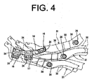
- the swing lever 31 is pivotally mounted to the movable base 21 through the pivot shaft 26.
- the swing lever 31 has a lever body 32 and a grip 33.
- the lever body 32 is pivotally mounted on the pivot shaft 26, and one end of the lever body 32 extends rightward out of the movable base 21.
- the grip 33 is provided at a position of the end of the lever body 32 or one end of the swing lever 31 as a first end.
- the other end of the lever body 32 extends over the hole 25 and the locating lug 34 is provided at a position of the other end of the lever body 32 adjacent to the hole 25.
- the locating lug 34 is inserted through the through hole 25 of the movable base 21 and further in the guide hole 15 of the stationary base 11 as shown in FIG.
- the direction of the center axis of the locating lug 34 is substantially the same as the direction in which the swing lever 31 is pivoted, and the shape of the lateral sides of the locating lug 34 is substantially same as the shape of the lateral sides of the recessed portions 17 and 18.
- the locating lug 34 is fit into the recessed portions 17 and 18 or moved along the arcuate portion 16 of the guide hole 15, thereby causing the movable base 21 to pivot in either leftward or rightward direction.
- a coil spring 35 as an urging means is connected between the other end of the swing lever 31 as the second end and the movable base 21 for urging the locating lug 34 rearwardly or toward the recessed portions 17 or 18.
- An elongated hole 36 as a shaft hole in which the pivot shaft 26 inserted is formed at a middle of the lever body 32, and the longitudinal direction of the elongated hole 36 is the substantially same as the direction in which the locating lug 34 moves along the guide hole 15. This allows the swing lever 31 to move for a distance corresponding to the clearance in the elongated hole 36 when the swing lever 31 is pivoted against the urging force of the coil spring 35 and the locating lug 34 is positioned at the arcuate portion 16 of the guide hole 15.
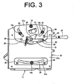
- the movable base 21 In the normal position of the vehicle seat assembly 20 in a forklift truck, as shown in FIG. 3 , the movable base 21 is not pivoted relative to the stationary base 11 or the seat assembly 20 on the movable base 21 faces straightforward. In this position, the locating lug 34 of the swing lever 31 is secured in the recessed portion 17 and, therefore, the movement of the movable base 21 in the pivoting direction is restricted and the vehicle seat assembly 20 faces straightforward. In the normal position of the seat assembly 20, the spring force of the coil spring 35 is applied to the swing lever 31 as a force in the direction in which the locating lug 34 is engaged with the recessed portion 17.
- the locating lug 34 is kept engaged with the recessed portion 17.
- the swing lever 31 may move relative to the pivot shaft 26 for a distance corresponding to the clearance in the elongated hole 36.
- the recessed portion 17 is wedge-shaped with its width narrowed toward its bottom, so that the locating lug 34 contacts with recessed portion 17 with no gap therebetween.
- the vehicle seat assembly 20 is pivoted clockwise direction as viewed, for example, in FIG. 3 , the operator's body is turned rightward and this is convenient for the operator to check for the rear of the vehicle body when the forklift truck is driven backward.
- the swing lever 31 is operated such that the locating lug 34 which is then engaged with the recessed portion 17 is moved toward the arcuate portion 16.
- the grip 33 is moved backward so that the swing lever 31 is pivoted against the urging force of the coil spring 35.
- the swing lever 31 since the swing lever 31 has an elongated hole 36 through which the pivot shaft 26 is inserted and, therefore, the swing lever 31 is movable relative to the pivot shaft 26, the locating lug 34 can be released easily from the recessed portion 17. This is because the distance between the pivot shaft 26 serving as the pivot and the locating lug 34 serving as the acting point is changed according to the variable clearance between the elongated hole 36 and the pivot shaft 26. In the preferred embodiment of the present invention, the difficulty in releasing the locating lug 34 from the recessed portion 17 because of failure in complete correspondence of circular arcs thereof is solves by the provision of the elongated hole 36 along which the swing lever 31 is movable relative to the movable base 21.
- the locating lug 34 when the locating lug 34 is fully released from the recessed portion 17, the locating lug 34 is positioned in the arcuate portion 16 of the guide hole 15 at a position where the locating lug 34 faces the recessed portion 17 as indicated by two-dot chain line.
- the swing lever 31 is then turned in clockwise direction as viewed from the top or pushed leftward thereby to pivot the movable base 21 in clockwise direction.
- the swing lever 31 is turned in counter-clockwise direction or pulled rightward to pivot the movable base 21 counter-clockwise.
- the locating lug 34 In pivoting the movable base 21 in counter-clockwise direction, the locating lug 34 is positioned facing the recessed portion 18 which is used for holding the movable base 21 at a position where the movable base 21 has turned in counter-clockwise direction for a predetermined distance from the aforementioned center position.
- the locating lug 34 in this position is shown by two-dot chain line at a position where it faces the recessed portion 18. Releasing the swing lever 31, the swing lever 31 is moved by the urging force of the coil spring 35 in the direction which causes the locating lug 34 to be engaged with the recessed portion 18.
- the swing lever 31 is moved relative to the pivot shaft 26 as needed thereby to facilitate the engagement of the locating lug 34 with recessed portion 18.
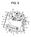
- the movable base 21 is pivoted clockwise relative to the stationary base 11 as shown in FIG. 5 and both lateral sides of the locating lug 34 are in contact with those of the recessed portion 18 with no gap formed therebetween.
- the vehicle seat assembly 20 is pivoted about an angle of 17 degrees in clockwise direction relative to an operator's platform facing toward of the vehicle body from the center position.
- the front of the body of the operator seated on operator's seat is turned rightward, and the vehicle seat assembly 20 which has been pivoted clockwise remains at this position unless the swing lever 31 is operated again.
- the swing lever 31 is operated by manipulation of the grip 33 of the swing lever 31 which is located on lateral side of the vehicle seat assembly 20.
- means for operating the swing lever 31 may be installed in an armrest which is provided on the vehicle seat.
- the operating means for the swing lever 31 such as the operating lever installed in the armrest is connected to the swing lever through a wire or the like. The swing lever is pivoted by operation of the operating means.
- the movable base 21 is pivoted by the operation of the grip 33 of the swing lever 31.
- the vehicle seat assembly 20 may be pivoted by twisting of the operator's body.
- the two recessed portions 17 and 18 are provided for holding the movable base 21 at the center or straightforward position and the position where the movable base 21 is pivoted clockwise for a predetermined angle from the center position.
- the number of the other recessed portions is not limited by the present invention.
- the spring force of the coil spring 35 is used as urging force.
- the urging force is not limited to the force of the coil spring 35. Any suitable means may be used for applying urging force the swing lever.
Claims (9)
- Sitzdrehvorrichtung eines Fahrzeugs (10) mit einem Fahrzeugaufbau, die einen stationären Grundkörper (11), der an dem Fahrzeugaufbau gesichert ist, einen beweglichen Grundkörper (21), der durch eine erste Drehachse (13) mit dem stationären Grundkörper (11) verbunden ist, eine Fahrzeugsitzbaugruppe (20), die an einer oberen Fläche des beweglichen Grundkörpers (21) montiert ist, und einen Schwenkhebel (31) hat, der Arretierungs- und Freigabepositionen des beweglichen Grundkörpers (21) relativ zu dem stationären Grundkörper (11) verändert,
dadurch gekennzeichnet, dass
der bewegliche Grundkörper (21) eine zweite Drehachse (26) zum Stützen des Schwenkhebels (31) hat, so dass der Schwenkhebel (31) drehbar ist,
der stationäre Grundkörper (11) ein Führungsloch (15) zum Definieren eines Bereichs hat, in dem der bewegliche Grundkörper (21) drehbar ist,
der Schwenkhebel (31) ein Langloch (36), in das die zweite Drehachse (26) eingesetzt ist, und eine Anordnungsnase (34) hat, die entlang des Führungslochs (15) geführt ist,
das Führungsloch (15) einen ausgesparten Abschnitt (17, 18) hat, mit dem die Anordnungsnase (34) durch Drehen des Schwenkhebels (31) in Eingriff ist, um dadurch den beweglichen Grundkörper (21) an dem stationären Grundkörper (11) in einer vorbestimmten Position zu fixieren, und
der Schwenkhebel (31) relativ zu der zweiten Drehachse (26) in Übereinstimmung mit der Form des Langlochs (36) beweglich ist. - Sitzdrehvorrichtung (10) nach Anspruch 1, wobei eine Längsrichtung des Langlochs (36) die im Wesentlichen gleiche ist wie die Richtung, in die sich die Anordnungsnase (34) entlang des Führungslochs (15) bewegt.
- Sitzdrehvorrichtung (10) nach Anspruch 1 oder Anspruch 2, wobei der ausgesparte Abschnitt (17, 18) derart keilförmig ist, dass die Breite des ausgesparten Abschnitts (17, 18) zu einem Ende des ausgesparten Abschnitts (17, 18) hin schmäler wird, eine Richtung der Mittelachse der Anordnungsnase (34) im Wesentlichen die gleiche ist wie eine Richtung, in die der Schwenkhebel (31) drehbar ist, und der ausgesparte Abschnitt (17, 18) die im Wesentlichen gleiche und komplementäre Form hat wie die Anordnungsnase (34).
- Sitzdrehvorrichtung (10) nach einem der Ansprüche 1 bis 3, wobei das Führungsloch (15) einen weiteren ausgesparten Abschnitt (17, 18) hat.
- Sitzdrehvorrichtung (10) nach einem der Ansprüche 1 bis 4, wobei das Führungsloch (15) einen bogenförmigen Abschnitt (16) hat.
- Sitzdrehvorrichtung (10) nach einem der Ansprüche 1 bis 5, wobei die Anordnungsnase (34) an einer Position eines zweiten Endes des Schwenkhebels (31) vorgesehen ist.
- Sitzdrehvorrichtung (10) nach einem der Ansprüche 1 bis 6, wobei der bewegliche Grundkörper (21) ein Drängbauteil zum Drängen des Schwenkhebels (31) durch seine Drängkraft in eine Richtung hat, in der die Anordnungsnase (34) mit dem ausgesparten Abschnitt (17, 18) in Eingriff ist, und ein Eingriff der Anordnungsnase (34) mit dem ausgesparten Abschnitt (17, 18) durch die Drängkraft gehalten wird.
- Sitzdrehvorrichtung (10) nach Anspruch 7, wobei das Drängbauteil eine Spiralfeder (35) ist.
- Sitzdrehvorrichtung (10) nach Anspruch 8, wobei die Spiralfeder (35) mit dem zweiten Ende des Schwenkhebels (31) verbunden ist.
Applications Claiming Priority (1)
| Application Number | Priority Date | Filing Date | Title |
|---|---|---|---|
| JP2006110405A JP4770561B2 (ja) | 2006-04-13 | 2006-04-13 | 車両用シート転回装置 |
Publications (2)
| Publication Number | Publication Date |
|---|---|
| EP1844975A1 EP1844975A1 (de) | 2007-10-17 |
| EP1844975B1 true EP1844975B1 (de) | 2009-07-22 |
Family
ID=38288473
Family Applications (1)
| Application Number | Title | Priority Date | Filing Date |
|---|---|---|---|
| EP07105951A Active EP1844975B1 (de) | 2006-04-13 | 2007-04-11 | Sitzdrehvorrichtung für ein Fahrzeug |
Country Status (4)
| Country | Link |
|---|---|
| US (1) | US7472958B2 (de) |
| EP (1) | EP1844975B1 (de) |
| JP (1) | JP4770561B2 (de) |
| DE (1) | DE602007001619D1 (de) |
Families Citing this family (21)
| Publication number | Priority date | Publication date | Assignee | Title |
|---|---|---|---|---|
| US7600732B2 (en) * | 2006-08-14 | 2009-10-13 | Ami Industries, Inc. | Aircraft interior equipment support |
| US7984946B2 (en) | 2007-07-24 | 2011-07-26 | Chirine M Zahar | Automotive vehicle safety seat |
| US20090127908A1 (en) * | 2007-10-04 | 2009-05-21 | John Kucharski | Seat Swivel Mechanism |
| DE102008059999A1 (de) * | 2008-12-02 | 2010-06-10 | GM Global Technology Operations, Inc., Detroit | Kraftfahrzeugsitz mit einer Verstellvorrichtung |
| US8424966B1 (en) | 2009-09-08 | 2013-04-23 | Lane Furniture Industries, Inc. | Seating with eccentric swivel |
| US8376462B2 (en) * | 2009-10-09 | 2013-02-19 | PAC Seating Systems, Inc. | Aircraft seat with adjustable armrests |
| US20110133527A1 (en) * | 2009-12-09 | 2011-06-09 | Elizabeth Taylor | Salon chair with swivel footrest |
| NO336043B1 (no) * | 2010-09-10 | 2015-04-27 | HTS Hans Torgersen & Sønn AS | Roterende barnesete for bruk i et kjøretøy |
| EP2635456B1 (de) * | 2010-11-05 | 2018-02-07 | Volvo Construction Equipment AB | Baumaschine mit verbesserter steuerungsergonomik |
| US8602903B2 (en) | 2011-04-12 | 2013-12-10 | Kids Ii, Inc. | Child support repositioning mechanism |
| DE102011103225B4 (de) * | 2011-06-01 | 2013-04-25 | Keiper Gmbh & Co. Kg | Fahrzeugsitz |
| DE102011108374A1 (de) * | 2011-07-22 | 2013-01-24 | Keiper Gmbh & Co. Kg | Fahrzeugsitz |
| US8936295B2 (en) | 2011-11-05 | 2015-01-20 | Bruno Independent Living Aids, Inc. | Articulated seating system |
| US9428276B1 (en) | 2015-02-19 | 2016-08-30 | PAC Seating Systems, Inc. | Swivel mechanism for vehicle seat |
| JP6912792B2 (ja) * | 2016-07-12 | 2021-08-04 | 和光工業株式会社 | 車両用シート装置 |
| DE102016220296A1 (de) * | 2016-10-18 | 2018-04-19 | Bayerische Motoren Werke Aktiengesellschaft | Drehbare Verbindungsanordnung für Topcase |
| FR3065922B1 (fr) * | 2017-05-04 | 2021-02-12 | Alstom Transp Tech | Dispositif de rotation d'un siege, notamment pour vehicule ferroviaire |
| DE102017212790A1 (de) * | 2017-07-26 | 2019-01-31 | Bayerische Motoren Werke Aktiengesellschaft | Verbindungsanordnung für seitliche Gepäckbehältnisse eines Motorrades |
| US10730409B2 (en) * | 2018-08-16 | 2020-08-04 | Sears Manufacturing Co. | Seat swivel limiter |
| JP6932469B2 (ja) * | 2019-12-27 | 2021-09-08 | コイト電工株式会社 | 座席装置 |
| CN112172621B (zh) * | 2020-09-30 | 2021-12-17 | 恺博(常熟)座椅机械部件有限公司 | 一种改善运动间隙的旋转座椅机构 |
Family Cites Families (22)
| Publication number | Priority date | Publication date | Assignee | Title |
|---|---|---|---|---|
| US2148187A (en) * | 1936-06-18 | 1939-02-21 | Karpen & Bros S | Reversible seat |
| US2266200A (en) * | 1937-11-04 | 1941-12-16 | James Leonard Spong | Vehicle seat |
| US2822858A (en) * | 1955-06-23 | 1958-02-11 | Mussler Kurt Erich | Swiveled front seat for automobiles |
| US3066979A (en) * | 1959-08-14 | 1962-12-04 | Rockwell Standard Co | Swivel seat constructions |
| US2992852A (en) * | 1959-09-04 | 1961-07-18 | Chrysler Corp | Swivel seat actuating mechanism for an automobile |
| US3013837A (en) * | 1960-07-01 | 1961-12-19 | Gen Motors Corp | Pivoted vehicle seat |
| US3104911A (en) * | 1960-09-07 | 1963-09-24 | Rockwell Standard Co | Automatic swivel seat |
| JPS537025A (en) * | 1976-07-07 | 1978-01-23 | Kyokuto Kaihatsu Kogyo Co Ltd | Auxiliary device for opening and closing rear stand door |
| US4417715A (en) * | 1981-03-05 | 1983-11-29 | National Seating Co. | Reversible transportation seat |
| JPS58192727A (ja) * | 1982-04-30 | 1983-11-10 | Showa Mfg Co Ltd | ガススプリングの組立方法及びその装置 |
| JPS58196238A (ja) * | 1982-05-13 | 1983-11-15 | Toyo Ink Mfg Co Ltd | 無電解メツキ方法 |
| JPS63137051A (ja) * | 1986-11-28 | 1988-06-09 | Ichikoh Ind Ltd | シ−トスライドのロツク機構 |
| CA2015353A1 (en) * | 1989-12-04 | 1991-06-04 | Dennis J. Gryp | Swivel seat, especially for vehicles |
| US5474353A (en) * | 1993-12-01 | 1995-12-12 | Hoover Universal, Inc. | Pivoting seat cushion arrangement for vehicle seat assemblies |
| JPH10109575A (ja) * | 1996-10-04 | 1998-04-28 | Ikeda Bussan Co Ltd | 車両用シートの回転調整機構 |
| FR2785862B1 (fr) * | 1998-11-13 | 2003-05-16 | Alstom Technology | Siege tournant, notamment pour vehicule ferroviaire |
| US6027170A (en) * | 1999-02-19 | 2000-02-22 | Paccar Inc | Rotating vehicle seat |
| US6513872B2 (en) * | 2001-05-18 | 2003-02-04 | De Sede Ag | Multipart upholstered furniture |
| JP2003341399A (ja) * | 2002-05-29 | 2003-12-03 | Nissan Motor Co Ltd | 産業車両のシート装置 |
| FR2843080B1 (fr) * | 2002-08-01 | 2004-09-17 | Antolin Grupo Ing Sa | Securite pour siege de vehicule, rotatif et calable dans au moins deux positions |
| TWM252584U (en) * | 2004-02-13 | 2004-12-11 | Pro Glory Entpr Co Ltd | A rotation mechanism for vehicle seat |
| US7219961B2 (en) * | 2005-04-06 | 2007-05-22 | Cnh America Llc | Pivoting seat |
-
2006
- 2006-04-13 JP JP2006110405A patent/JP4770561B2/ja active Active
-
2007
- 2007-04-11 US US11/786,576 patent/US7472958B2/en active Active
- 2007-04-11 DE DE602007001619T patent/DE602007001619D1/de active Active
- 2007-04-11 EP EP07105951A patent/EP1844975B1/de active Active
Also Published As
| Publication number | Publication date |
|---|---|
| DE602007001619D1 (de) | 2009-09-03 |
| US7472958B2 (en) | 2009-01-06 |
| US20070246987A1 (en) | 2007-10-25 |
| EP1844975A1 (de) | 2007-10-17 |
| JP4770561B2 (ja) | 2011-09-14 |
| JP2007283808A (ja) | 2007-11-01 |
Similar Documents
| Publication | Publication Date | Title |
|---|---|---|
| EP1844975B1 (de) | Sitzdrehvorrichtung für ein Fahrzeug | |
| EP2565071B1 (de) | Gleitschienenvorrichtung für ein fahrzeug | |
| US7887134B2 (en) | Interlock for a seat recliner mechanism | |
| US20080041129A1 (en) | Locking mechanism for a rotation seat | |
| US8590973B2 (en) | Lock device for vehicular seat | |
| JP5662070B2 (ja) | 車両用スライドレール装置 | |
| JP5530919B2 (ja) | 特に車両後部座席のシートバックのための傾斜アジャスタ | |
| WO2011136049A1 (ja) | 車両用スライドレール装置 | |
| EP1995110A2 (de) | Vorrichtung zur Sitzeinstellung für ein Fahrzeug | |
| JPS6144485B2 (de) | ||
| US10519623B2 (en) | Stand of front loader, front loader, and work vehicle with supporting-time guiding hole | |
| JP2009201783A (ja) | 車両用シートリクライニング装置 | |
| US9090179B2 (en) | Vehicle seat reclining device | |
| JP3999494B2 (ja) | 車両用シートロック装置 | |
| US20200101870A1 (en) | Seat release mechanism | |
| KR20150090289A (ko) | 차량용 암레스트 록킹장치 | |
| EP1407919B1 (de) | Betätigungshebel und diesen aufweisender sitz | |
| EP0976606B1 (de) | Neigungsverstellsystem für einen Sitz | |
| JP5259114B2 (ja) | ヘッドレスト及び該ヘッドレストを備えた車両用シート | |
| JP4562605B2 (ja) | 車両用シートのシートバック前倒し機構 | |
| EP0911208B1 (de) | Sitzverstellvorrichtung | |
| JP2002293224A (ja) | 自動車におけるブレーキペダル回動制御装置 | |
| WO2023026547A1 (ja) | チャイルドシート及びその着脱方法 | |
| JP3127793B2 (ja) | シートスライド装置 | |
| JP5991027B2 (ja) | シートスライド装置 |
Legal Events
| Date | Code | Title | Description |
|---|---|---|---|
| PUAI | Public reference made under article 153(3) epc to a published international application that has entered the european phase |
Free format text: ORIGINAL CODE: 0009012 |
|
| 17P | Request for examination filed |
Effective date: 20070411 |
|
| AK | Designated contracting states |
Kind code of ref document: A1 Designated state(s): AT BE BG CH CY CZ DE DK EE ES FI FR GB GR HU IE IS IT LI LT LU LV MC MT NL PL PT RO SE SI SK TR |
|
| AX | Request for extension of the european patent |
Extension state: AL BA HR MK YU |
|
| AKX | Designation fees paid |
Designated state(s): DE FR |
|
| GRAP | Despatch of communication of intention to grant a patent |
Free format text: ORIGINAL CODE: EPIDOSNIGR1 |
|
| GRAS | Grant fee paid |
Free format text: ORIGINAL CODE: EPIDOSNIGR3 |
|
| GRAA | (expected) grant |
Free format text: ORIGINAL CODE: 0009210 |
|
| AK | Designated contracting states |
Kind code of ref document: B1 Designated state(s): DE FR |
|
| REF | Corresponds to: |
Ref document number: 602007001619 Country of ref document: DE Date of ref document: 20090903 Kind code of ref document: P |
|
| PLBE | No opposition filed within time limit |
Free format text: ORIGINAL CODE: 0009261 |
|
| STAA | Information on the status of an ep patent application or granted ep patent |
Free format text: STATUS: NO OPPOSITION FILED WITHIN TIME LIMIT |
|
| 26N | No opposition filed |
Effective date: 20100423 |
|
| REG | Reference to a national code |
Ref country code: FR Ref legal event code: PLFP Year of fee payment: 10 |
|
| REG | Reference to a national code |
Ref country code: FR Ref legal event code: PLFP Year of fee payment: 11 |
|
| REG | Reference to a national code |
Ref country code: FR Ref legal event code: PLFP Year of fee payment: 12 |
|
| PGFP | Annual fee paid to national office [announced via postgrant information from national office to epo] |
Ref country code: FR Payment date: 20230309 Year of fee payment: 17 |
|
| P01 | Opt-out of the competence of the unified patent court (upc) registered |
Effective date: 20230519 |
|
| PGFP | Annual fee paid to national office [announced via postgrant information from national office to epo] |
Ref country code: DE Payment date: 20230228 Year of fee payment: 17 |