EP1842811A2 - Blattzuführungsvorrichtung und Bilderzeugungsvorrichtung - Google Patents
Blattzuführungsvorrichtung und Bilderzeugungsvorrichtung Download PDFInfo
- Publication number
- EP1842811A2 EP1842811A2 EP07250878A EP07250878A EP1842811A2 EP 1842811 A2 EP1842811 A2 EP 1842811A2 EP 07250878 A EP07250878 A EP 07250878A EP 07250878 A EP07250878 A EP 07250878A EP 1842811 A2 EP1842811 A2 EP 1842811A2
- Authority
- EP
- European Patent Office
- Prior art keywords
- sheet
- sheet feeding
- cleaning member
- cleaning
- conveying
- Prior art date
- Legal status (The legal status is an assumption and is not a legal conclusion. Google has not performed a legal analysis and makes no representation as to the accuracy of the status listed.)
- Granted
Links
- 238000004140 cleaning Methods 0.000 claims abstract description 176
- 239000000126 substance Substances 0.000 claims description 43
- 239000000428 dust Substances 0.000 claims description 23
- 230000002093 peripheral effect Effects 0.000 description 28
- 230000000052 comparative effect Effects 0.000 description 10
- 230000007246 mechanism Effects 0.000 description 8
- 229920001971 elastomer Polymers 0.000 description 7
- 230000002265 prevention Effects 0.000 description 7
- 229920000139 polyethylene terephthalate Polymers 0.000 description 6
- 239000005020 polyethylene terephthalate Substances 0.000 description 6
- 238000010410 dusting Methods 0.000 description 5
- 239000000463 material Substances 0.000 description 5
- 239000000843 powder Substances 0.000 description 5
- 239000010802 sludge Substances 0.000 description 5
- 230000000694 effects Effects 0.000 description 4
- 230000002950 deficient Effects 0.000 description 3
- 230000006872 improvement Effects 0.000 description 3
- 238000010586 diagram Methods 0.000 description 2
- -1 polyethylene terephthalate Polymers 0.000 description 2
- JOYRKODLDBILNP-UHFFFAOYSA-N Ethyl urethane Chemical compound CCOC(N)=O JOYRKODLDBILNP-UHFFFAOYSA-N 0.000 description 1
- NIXOWILDQLNWCW-UHFFFAOYSA-N acrylic acid group Chemical group C(C=C)(=O)O NIXOWILDQLNWCW-UHFFFAOYSA-N 0.000 description 1
- 230000005540 biological transmission Effects 0.000 description 1
- 210000000078 claw Anatomy 0.000 description 1
- 239000011248 coating agent Substances 0.000 description 1
- 230000008878 coupling Effects 0.000 description 1
- 238000010168 coupling process Methods 0.000 description 1
- 238000005859 coupling reaction Methods 0.000 description 1
- 238000007599 discharging Methods 0.000 description 1
- 239000000835 fiber Substances 0.000 description 1
- 238000000034 method Methods 0.000 description 1
- 229920002635 polyurethane Polymers 0.000 description 1
- 239000004814 polyurethane Substances 0.000 description 1
- 230000008569 process Effects 0.000 description 1
- 230000000630 rising effect Effects 0.000 description 1
- 238000007789 sealing Methods 0.000 description 1
- 238000000926 separation method Methods 0.000 description 1
- 230000003746 surface roughness Effects 0.000 description 1
Images

Classifications
-
- B—PERFORMING OPERATIONS; TRANSPORTING
- B65—CONVEYING; PACKING; STORING; HANDLING THIN OR FILAMENTARY MATERIAL
- B65H—HANDLING THIN OR FILAMENTARY MATERIAL, e.g. SHEETS, WEBS, CABLES
- B65H5/00—Feeding articles separated from piles; Feeding articles to machines
- B65H5/06—Feeding articles separated from piles; Feeding articles to machines by rollers or balls, e.g. between rollers
- B65H5/062—Feeding articles separated from piles; Feeding articles to machines by rollers or balls, e.g. between rollers between rollers or balls
-
- G—PHYSICS
- G03—PHOTOGRAPHY; CINEMATOGRAPHY; ANALOGOUS TECHNIQUES USING WAVES OTHER THAN OPTICAL WAVES; ELECTROGRAPHY; HOLOGRAPHY
- G03G—ELECTROGRAPHY; ELECTROPHOTOGRAPHY; MAGNETOGRAPHY
- G03G15/00—Apparatus for electrographic processes using a charge pattern
- G03G15/65—Apparatus which relate to the handling of copy material
- G03G15/6502—Supplying of sheet copy material; Cassettes therefor
- G03G15/6511—Feeding devices for picking up or separation of copy sheets
-
- B—PERFORMING OPERATIONS; TRANSPORTING
- B65—CONVEYING; PACKING; STORING; HANDLING THIN OR FILAMENTARY MATERIAL
- B65H—HANDLING THIN OR FILAMENTARY MATERIAL, e.g. SHEETS, WEBS, CABLES
- B65H2301/00—Handling processes for sheets or webs
- B65H2301/50—Auxiliary process performed during handling process
- B65H2301/53—Auxiliary process performed during handling process for acting on performance of handling machine
- B65H2301/531—Cleaning parts of handling machine
-
- G—PHYSICS
- G03—PHOTOGRAPHY; CINEMATOGRAPHY; ANALOGOUS TECHNIQUES USING WAVES OTHER THAN OPTICAL WAVES; ELECTROGRAPHY; HOLOGRAPHY
- G03G—ELECTROGRAPHY; ELECTROPHOTOGRAPHY; MAGNETOGRAPHY
- G03G2215/00—Apparatus for electrophotographic processes
- G03G2215/00362—Apparatus for electrophotographic processes relating to the copy medium handling
- G03G2215/00367—The feeding path segment where particular handling of the copy medium occurs, segments being adjacent and non-overlapping. Each segment is identified by the most downstream point in the segment, so that for instance the segment labelled "Fixing device" is referring to the path between the "Transfer device" and the "Fixing device"
- G03G2215/00396—Pick-up device
Definitions
- the present invention relates to a sheet feeding device used for an image forming apparatus such as a copier, a printer, a facsimile, and a multi-functional machine having the functions thereof and more particularly to a sheet feeding device having a cleaning member for removing foreign substances such as paper dust adhered to the outer peripheral surface of a conveying member and an image forming apparatus having the sheet feeding device.
- a foreign substance removing device of the image forming apparatus makes a fixing type cleaning member (a flexible member such as a brush, felt, or a PET sheet) touch a roller member for conveying recording sheets, thereby removes foreign substances such as paper dust. Further, it makes a cleaning roller (a brush, felt, etc.) touch conveyed recording sheets, thereby removes foreign substances such as paper dust.
- a fixing type cleaning member a flexible member such as a brush, felt, or a PET sheet
- a cleaning roller a brush, felt, etc.
- Unexamined Japanese Patent Application Publication No. 11-52641 discloses a foreign substance removing device for making a fixed type cleaning member such as felt touch a conveying roller, thereby cleaning the surface of each recording sheet by the conveying roller.
- Unexamined Japanese Patent Application Publication No. 11-208918 makes a brush touch a cleaning roller for cleaning conveyed recording sheets, thereby cleans the cleaning roller.
- Unexamined Japanese Patent Application Publication No. 08-314344 is of a type of making a cleaning roller touch conveyed recording sheets.
- Unexamined Japanese Patent Application Publication No. 2004-224451 makes a rotating brush roller touch a conveying roller, thereby cleans the conveying roller, makes a rotary roller touch the brush roller, thereby cleans the brush roller, and furthermore makes a flexible sheet touch the brush roller, thereby cleans the rotary roller.
- Unexamined Japanese Patent Application Publication No. 2004-137076 (paragraph 0101, Fig. 9(a)), in a case that a conveying roller and a foreign substance removing member are rotated in the opposite direction and a case that they are rotated in the same direction, provides a speed difference between the moving speed of the tip of the foreign substance removing member and the moving speed of the peripheral surface of the conveying roller.
- the foreign substance removing device for making a fixing type cleaning member touch the aforementioned feed roller and conveying roller, thereby removing foreign substances or making a cleaning roller such as a rotating brush touch a conveyed transfer material, thereby removing foreign substances and in the image forming apparatus using it, foreign substances such as paper dust cannot be stably removed over a long period of time, thus a problem arises that entering of foreign substances into the transfer area cannot be reduced for a long time.
- the pickup roller of the sheet feeding device must send surely sheets to the feed roller and the pressurizing force of the pickup roller to sheets must be set to an appropriate load.
- a system of applying pressurizing force by the own weights of the pickup roller and holder is effective.
- the cleaning mechanism for cleaning the pickup roller is made larger, a-problem arises that an appropriate load cannot be given.
- An object of the present invention is to provide a sheet feeding device for eliminating the aforementioned faults, enabling removal of foreign substances such as paper dust over a long period of time, reducing entry of foreign substances into the transfer area, realizing miniaturization of the cleaning mechanism, and obtaining a good image quality and an image forming apparatus using the concerned device.
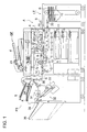
- Fig. 1 is a schematic view of the image forming apparatus composed of an image forming apparatus main body A, a finisher FS, a large capacity sheet feeding device LT, and an automatic document feeder DF.
- the image forming apparatus main body A includes an image forming section 1, a fixing device 9, and a sheet conveying system.
- the image forming section 1 is composed of a charging unit 3 arranged around an image carrier 2, an image exposure unit 4, a developing unit 5, a transferring unit 6, a discharging unit 7A, a separation claw 7B, and a cleaning unit 8.
- the sheet conveying system is constituted by a first conveying section composed of a sheet feeding cassette (sheet storing section) 10, a first sheet feeding unit 11, a second sheet feeding unit 12, a conveying unit 13, a sheet ejecting unit 14, and a manual sheet feeding unit 15 and a sheet circulating and re-feeding section for circulating and re-feeding sheets S.
- a sheet feeding cassette sheet storing section
- the sheet conveying system is constituted by a first conveying section composed of a sheet feeding cassette (sheet storing section) 10, a first sheet feeding unit 11, a second sheet feeding unit 12, a conveying unit 13, a sheet ejecting unit 14, and a manual sheet feeding unit 15 and a sheet circulating and re-feeding section for circulating and re-feeding sheets S.
- the sheet feeding cassette 10 and first sheet feeding unit 11 are formed by a plurality of sheet feeding units (three stories shown in Fig. 1) and store and feed the sheets S of several kinds of sizes.
- the sheets S sent from a sheet feeding device 20 of the large capacity sheet feeding device LT are sent to the second sheet unit 12.
- a document "d" loaded on the document table of the automatic document feeder DF is conveyed by a document feeding device 21 and the document image is read by the image reading device.
- the processes of charging, exposing, developing, transferring, separating, and cleaning are performed.
- Each of the sheets S sent from the sheet feeding cassette 10, manual sheet feeding unit 15, and large capacity sheet feeding device LT is transferred an image by the transferring unit 6.
- the sheet S carrying the image is fixed by the fixing unit 9, is ejected from the sheet ejecting unit 14, and is sent to the finisher FS.
- the finisher FS is composed of an inlet conveying section 30, a shifting unit 31, a stacking unit 32, a stapling unit 33, a cover sheet feeding unit 34, and a sheet ejecting unit 35.
- Cover sheet K fed by the cover sheet feeding unit 34 is conveyed by the conveyance roller group and is stored in the stacking unit 32.
- the cover sheet K is stacked on a plurality of sheets S stored in the stacking unit 32 and form a front cover sheet and a back cover sheet. Further, the cover sheet K can be used as an inserting sheet inserted between the plurality of sheets S.
- the sheets S bound are interposed and conveyed by the sheet ejecting unit 35 and are ejected and stacked on a main tray 36.
- the sheet feeding device can be applied to the first sheet feeding unit 11 and manual sheet feeding unit 15 of the sheet feeding cassette (sheet storing section) 10 arranged in the image forming apparatus main body A, the sheet feeding device 20 of the large capacity sheet feeding device LT, the document feeding device 21 of the automatic document feeder DF, and the cover sheet feeding unit 34 of the finisher FS.
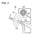
- Fig. 2 is a cross sectional view of the second sheet feeding unit 12 of the image forming apparatus main body A shown in Fig. 1.
- the second sheet feeding unit 12 includes a first cleaning member (hereinafter, referred to as a cleaning brush) 123 composed of a drive roller (conveying member) 121 for interposing and conveying the sheets S, a driven roller 122, and a cleaning brush rotating in sliding contact with the drive roller 121, a second cleaning member 124 for rotating in sliding contact with the cleaning brush 123, and a third flexible cleaning member 125 in contact with the outer peripheral surface of the second cleaning member 124.
- a cleaning brush composed of a drive roller (conveying member) 121 for interposing and conveying the sheets S, a driven roller 122, and a cleaning brush rotating in sliding contact with the drive roller 121, a second cleaning member 124 for rotating in sliding contact with the cleaning brush 123, and a third flexible cleaning member 125 in contact with the outer peripheral surface of the second cleaning member 124.
- the drive roller 121 is driven to rotate clockwise, and the cleaning brush 123 is driven to rotate counterclockwise by a drive unit not drawn, and the second cleaning member 124 is driven to rotate clockwise by a drive unit not drawn.
- the third cleaning member 125 is in pressure contact with the outer peripheral surface of the second cleaning member 124 counter to the rotation thereof.
- the cleaning brush 123 is formed by a conductive brush.
- the specifications and characteristics of the conductive brush will be described later.
- the specifications and characteristics of the drive roller 121 will also be described later.
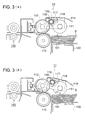
- Figs. 3(a) and 3(b) are plane cross sectional views of the sheet feeding device, and Fig. 3(a) shows the state before start of sheet feed, and Fig. 3(b) shows the state at time of sheet feed.
- the manual sheet feeding unit 15, the sheet feeding device 20 of the large capacity sheet feeding device LT, the document feeding device 21 of the automatic document feeder DF, and the cover sheet feeding unit 34 of the finisher FS have an almost similar structure as that of the first sheet feeding unit 11, so that hereinafter, the first sheet feeding unit 11 will be explained as representation.
- the sheets S loaded on a rise-and-fall plate 101 in the sheet feeding cassette 10 move up by a rise-and-fall member 102 moving up and down by a motor not drawn and when the top of the sheets S reaches a predetermined position where it makes contact with the outer peripheral surface of a pickup roller (first conveying member) 111, the top of the sheets S is detected by a sensor not drawn, and the rise-and-fall plate 101 stops rising.
- a predetermined pressure P1 is applied to the top of the sheets S by the own weights of the pickup roller 111 and a holder 114.
- the pickup roller 111 and a feed roller (second conveying member) 112 start rotation.
- the pickup roller 111 making pressure contact with the top of the sheets S at the predetermined pressure P1 sends the sheets S to the nip position between the feed roller 112 and a multi-feed prevention roller (reverse roller) 113, and then separates from the sheet surface.
- the multi-feed prevention roller 113 is driven in the opposite direction of the conveying direction of the sheets S via a torque limiter not shown and makes pressure contact with the feed roller 112 at a predetermined pressure P2 by a spring not drawn.
- the multi-feed prevention roller 113 when there exist no sheets S at the nip position and the feed roller 112 directly makes contact or when one sheet S is sent to the nip position, since the torque limiter slides at more than the limit torque, rotates by following the feed roller 112, thereby conveys the one sheet S.
- the limit torque overcomes the frictional force between the sheets, rotates reversely the multi-feed prevention roller 113, presses back the lower side sheets S, prevents feeding of a large number of sheets, thereby conveys one sheet S.
- the pickup roller 111 swings around the rotary shaft of the feed roller 112 and makes contact with the top of the sheets S by its own weight. Simultaneously, an electromagnetic clutch CL which will be described later is put into the connection state, and the feed roller 112 starts rotation, and furthermore, the pickup roller 111 starts rotation by a drive transmission unit which will be described later.
- the sheets S are sent out by the rotation of the pickup roller 111, are conveyed to the nip position where the feed roller 112 and multi-feed prevention roller 113 make pressure contact with each other, are handled one by one, and reach a conveyance roller pair 115 on the downstream side in the conveying direction.
- the first sheet feeding unit 11 and the conveyance roller pair 115 constitute a conveying unit.
- the electromagnetic clutch CL enters the non-contact state, and the sheets S, by interposing and conveying by the conveyance roller pair 115, are pulled out and conveyed from the nip position where the feed roller 112 and multi-feed prevention roller 113 make pressure contact with each other.
- a first cleaning member (hereinafter, referred to as a cleaning brush) 116, a second cleaning member 117, a third cleaning member 118, and a covering member 119 are arranged on the first document feeding unit 11, above the space where the pickup roller 111 and feed roller 112 face each other.
- the cleaning brush 116 rotates in sliding contact with the outer peripheral surface of the pickup roller 111 and the outer peripheral surface of the feed roller 112.
- the cleaning brush 116 is rotated by a driving unit, which will be described later and rotates counterclockwise as shown in the drawing.
- the cleaning brush 116 and pickup roller 111 rotate with a speed difference in the same direction at the sliding contact position.
- the cleaning brush 116 and feed roller 112 rotate with a speed difference in the same direction at the sliding contact position.
- the cleaning brush 116 comes in sliding contact with the feed roller 112, thereby removes paper dust and foreign substances adhered to them.
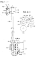
- Fig. 4(a) is a plane cross sectional view showing the rotation driving mechanism of the cleaning brush 116 and Fig. 4(b) is a front view thereof.
- a driving source not drawn is connected to a coupling 110 and rotates continuously a gear G1.
- the gear G1 meshes with a gear G2 and rotates a rotary shaft 110A.
- the electromagnetic clutch CL installed at the shaft end of the rotary shaft 110A turns on or off rotation drive of the rotary shaft 110A.
- the cleaning brush 116 is fixed and rotates counterclockwise together with the rotary shaft 110B as shown in the drawing.
- a gear G6 fixed to the other end of the rotary shaft 110B rotates a gear G7 fixed to a rotary shaft 110D of the second cleaning member 117.
- the gear G7 By the rotation of the gear G7, the second cleaning member 117 rotates clockwise as shown in the Fig. 2.
- a holder 114 of the first sheet feeding unit 11 bears rotatably the rotary shaft 110A, rotary shaft 110B, and second cleaning member 117 and fixes the third cleaning member 118 and one end of the covering member 119.
- the tip portion of the third cleaning member 118 is in pressure contact with the outer peripheral surface of the second cleaning member 117 counter to the rotation thereof.
- the tip portion of the covering member 119 is in pressure contact with the outer peripheral surface of the second cleaning member 117 with trailing the rotation thereof.
- the holder 114 of the first sheet feeding unit 11 is supported rotatably around the rotary shaft 110A of the feed roller 112.
- the stop of the upper mechanism of the first sheet feeding unit 11 composed of the pickup roller 111, cleaning brush 116, second cleaning member. 117, third cleaning member 118, covering member 119, and holder 114 is canceled and the pickup roller 111 swings and pressurizes the top of the sheets S stored in the sheet feeding cassette 10 at the predetermined pressure P1 by its own weight and sends out the sheets S.
- the cleaning unit composed of the cleaning brush 116, second cleaning member 117, third cleaning member 118, and covering member 119 is formed small and light, so that it holds the predetermined pressure P1 and can send out surely a minimum number of sheets S.
- the cleaning brush 116 and second cleaning member 117 are installed compatibly with the pickup roller 111 and feed roller 112, thus the first sheet feeding unit 11 can be made smaller and lighter.
- the degree of freedom of design of the first sheet feeding unit 11 having a constitution of sending appropriately sheets at the pressure by its own weight is made wider.
- Fig. 5 is a cross sectional view of the cleaning unit of a comparative example having a fixed brush. Further, with respect to the numerals used in the drawing, to the same sheet feeding mechanism as that shown in Fig. 3, the same numerals are assigned.
- a cleaning member (cleaning brush) 116A fixed to the support plate is arranged on the upper part of the pickup roller 111.
- the cleaning member 116A removes foreign substances adhered to the outer peripheral surface of the pickup roller 111 in sliding contact with the outer peripheral surface of the pickup roller 111.
- a cleaning member (cleaning brush) 116B fixed to the support plate is arranged on the upper part of the feed roller 112.
- the cleaning member 116B removes foreign substances adhered to the outer peripheral surface of the feed roller 112 in sliding contact with the outer peripheral surface of the feed roller 112.
- a cleaning member (cleaning brush) 116C is arranged on the upper part of a drive roller 115A of the conveyance roller pair 115.
- the cleaning member 116C removes foreign substances adhered to the outer peripheral surface of the drive roller 115A in sliding contact with the outer peripheral surface.of the drive roller 115A.
- Table 1 Linear speed relation-ship Feed roller (112) Cleaning brush (116) Outside diameter (mm) Constant of gear G3 speed ratio (V1) Overlap amount (mm) Outside diameter (mm) Constant of gear G4 Linear speed ratio (V2) Relative linear speed ratio V2-V1
- Table 1 shows an example of the feed roller 112 and cleaning brush 116.
- the overlap amounts of the outside diameter of the cleaning brush 116 shifted into the outside diameter of the feed roller 112 are all 1.23 mm.
- Fig. 6 is a characteristic diagram of the measured results of changes in the coefficient of friction of the outer peripheral surface of the feed roller 112.
- the cleaning brush 116 rotates in the same direction in the linear speed relationship of V1 > V2 and stains of foreign substances such as paper dust, dusting powder, and ink sludge are transferred from the pickup roller 111 and feed roller 112 to the cleaning brush 116. Foreign substances adhered to the cleaning brush 116 are collected by the second cleaning member 117 and then is removed by the third cleaning member 118.
- the feed roller 112 is drawn by the sheets S held and conveyed by the conveyance roller pair 115 and is rotated at the linear speed V1, though the cleaning brush 116 is stopped, and the linear speed V2 of the tip of the cleaning brush 116 is zero.
- the pickup roller 111 and feed roller 112 are driven to rotate at the linear speed V1, so that the relationship of linear speeds of V1 > V2 is kept unchanged.
- the cleaning brush 116 is stopped, foreign substances collected at a predetermined location of the cleaning brush 116 are collected by the second cleaning member 117 at feed start time of the succeeding sheets S and then are removed by the third cleaning member 118.
- the cleaning brush 123 rotating forward in the linear speed relationship of V1 > V2 cleans the outer periphery surface of the conveying roller 121 in contact with it. Further, the cleaning brush 123 is refreshed by the second cleaning member 124 and is cleaned more surely by the third cleaning 125.
- the pickup roller 111 and feed roller 112 which are covered with EDPM rubber with a high coefficient of friction ⁇ have high sheet conveying force at an early stage of print, while when feeding off-set printed sheets S, dusting powder, paper dust, and ink sludge adhered to the sheets S before feeding are transferred onto the roller surface and are hardly removed, thus the durability of sheet conveyance is lowered.
- the reason is that the EDPM rubber with a high coefficient of friction ⁇ has a property of easily pulling in foreign substances such as dusting powder, paper dust, and ink sludge inside the rubber.
- the finisher of the image forming apparatus of the present invention is not limited to it and can be applied to a sheet feeding device of a finisher such as a pasting bookbinding device, a small paper cutter, a cover-wrapping bookbinding device, and a sealing device.
- the finisher connected to a copier is explained.
- the finisher can be applied to an image forming system connected of an image forming apparatus such as a light printing machine, a printer, a facsimile, and a multi-functional machine.
- the present invention can provide a foreign substance removing device for enabling removal of foreign substances such as paper dust over a long period of time, reducing entry of foreign substances into the transfer area, realizing miniaturization of the cleaning mechanism, and obtaining a good image quality and an image forming apparatus using the concerned device.
Landscapes
- Engineering & Computer Science (AREA)
- Mechanical Engineering (AREA)
- Physics & Mathematics (AREA)
- General Physics & Mathematics (AREA)
- Sheets, Magazines, And Separation Thereof (AREA)
- Feeding Of Articles By Means Other Than Belts Or Rollers (AREA)
Applications Claiming Priority (1)
| Application Number | Priority Date | Filing Date | Title |
|---|---|---|---|
| JP2006102847A JP2007276914A (ja) | 2006-04-04 | 2006-04-04 | 給紙装置及び画像形成装置 |
Publications (3)
| Publication Number | Publication Date |
|---|---|
| EP1842811A2 true EP1842811A2 (de) | 2007-10-10 |
| EP1842811A3 EP1842811A3 (de) | 2010-09-22 |
| EP1842811B1 EP1842811B1 (de) | 2011-11-23 |
Family
ID=38180297
Family Applications (1)
| Application Number | Title | Priority Date | Filing Date |
|---|---|---|---|
| EP07250878A Active EP1842811B1 (de) | 2006-04-04 | 2007-03-02 | Blattzuführungsvorrichtung und Bilderzeugungsvorrichtung |
Country Status (3)
| Country | Link |
|---|---|
| US (1) | US7711309B2 (de) |
| EP (1) | EP1842811B1 (de) |
| JP (1) | JP2007276914A (de) |
Cited By (1)
| Publication number | Priority date | Publication date | Assignee | Title |
|---|---|---|---|---|
| EP2455225A1 (de) * | 2010-11-19 | 2012-05-23 | Kyocera Mita Corporation | Antriebsmechanismus und Bilderzeugungsvorrichtung |
Families Citing this family (8)
| Publication number | Priority date | Publication date | Assignee | Title |
|---|---|---|---|---|
| US8100398B2 (en) * | 2009-04-22 | 2012-01-24 | Hewlett-Packard Development Company, L.P. | Printer media transport system |
| US8360415B1 (en) | 2012-02-21 | 2013-01-29 | Xerox Corporation | Automatic feed roll cleaning system |
| JP2015179115A (ja) * | 2014-03-18 | 2015-10-08 | 富士ゼロックス株式会社 | 定着装置及び画像形成装置 |
| JP7047252B2 (ja) * | 2017-03-10 | 2022-04-05 | セイコーエプソン株式会社 | 古紙供給装置、シート製造装置 |
| CN110582404B (zh) * | 2017-05-01 | 2022-06-03 | 惠普发展公司,有限责任合伙企业 | 调节器模块和成像设备 |
| JP2019081630A (ja) * | 2017-10-30 | 2019-05-30 | キヤノン株式会社 | 画像形成装置及び搬送装置 |
| WO2021251964A1 (en) * | 2020-06-10 | 2021-12-16 | Hewlett-Packard Development Company, L.P. | Printer pick tire cleaning |
| CN112026335B (zh) * | 2020-09-11 | 2021-12-17 | 浙江华熠印刷科技股份有限公司 | 一种纸板加工用印刷装置及其使用方法 |
Citations (3)
| Publication number | Priority date | Publication date | Assignee | Title |
|---|---|---|---|---|
| JPH11208918A (ja) * | 1998-01-26 | 1999-08-03 | Canon Inc | 画像形成装置及び給紙装置 |
| JP2004137076A (ja) * | 2002-08-20 | 2004-05-13 | Ricoh Co Ltd | 異物除去装置、シート搬送装置、画像読取装置、および画像形成装置 |
| JP2004224451A (ja) * | 2003-01-20 | 2004-08-12 | Konica Minolta Holdings Inc | 異物除去装置及び画像形成装置 |
Family Cites Families (6)
| Publication number | Priority date | Publication date | Assignee | Title |
|---|---|---|---|---|
| JPH08314344A (ja) | 1995-05-19 | 1996-11-29 | Canon Inc | 画像形成装置 |
| JPH1152641A (ja) | 1997-08-01 | 1999-02-26 | Canon Inc | 画像形成装置 |
| US6055407A (en) * | 1998-03-10 | 2000-04-25 | Canon Kabushiki Kaisha | Sheet feeding device and image forming apparatus having the sheet feeding device |
| NL1010934C2 (nl) * | 1998-12-31 | 2000-07-03 | Neopost Bv | Inrichting voor het separeren van vellen. |
| JP4696271B2 (ja) * | 2006-02-27 | 2011-06-08 | コニカミノルタビジネステクノロジーズ株式会社 | 給紙装置及び画像形成装置 |
| JP2007246206A (ja) * | 2006-03-15 | 2007-09-27 | Konica Minolta Business Technologies Inc | 給紙装置及び画像形成装置 |
-
2006
- 2006-04-04 JP JP2006102847A patent/JP2007276914A/ja active Pending
-
2007
- 2007-03-02 EP EP07250878A patent/EP1842811B1/de active Active
- 2007-03-05 US US11/713,843 patent/US7711309B2/en active Active
Patent Citations (3)
| Publication number | Priority date | Publication date | Assignee | Title |
|---|---|---|---|---|
| JPH11208918A (ja) * | 1998-01-26 | 1999-08-03 | Canon Inc | 画像形成装置及び給紙装置 |
| JP2004137076A (ja) * | 2002-08-20 | 2004-05-13 | Ricoh Co Ltd | 異物除去装置、シート搬送装置、画像読取装置、および画像形成装置 |
| JP2004224451A (ja) * | 2003-01-20 | 2004-08-12 | Konica Minolta Holdings Inc | 異物除去装置及び画像形成装置 |
Cited By (1)
| Publication number | Priority date | Publication date | Assignee | Title |
|---|---|---|---|---|
| EP2455225A1 (de) * | 2010-11-19 | 2012-05-23 | Kyocera Mita Corporation | Antriebsmechanismus und Bilderzeugungsvorrichtung |
Also Published As
| Publication number | Publication date |
|---|---|
| US7711309B2 (en) | 2010-05-04 |
| EP1842811A3 (de) | 2010-09-22 |
| US20070231033A1 (en) | 2007-10-04 |
| EP1842811B1 (de) | 2011-11-23 |
| JP2007276914A (ja) | 2007-10-25 |
Similar Documents
| Publication | Publication Date | Title |
|---|---|---|
| EP1842811B1 (de) | Blattzuführungsvorrichtung und Bilderzeugungsvorrichtung | |
| CN102020128B (zh) | 供纸装置以及图像形成装置 | |
| EP1908713B1 (de) | Blattfördervorrichtung und damit ausgestattete Bildgebungsvorrichtung | |
| EP1961683B1 (de) | Blattzuführungsvorrichtung und Bilderzeugungsvorrichtung damit | |
| US20070257424A1 (en) | Sheet feeding device and image forming apparatus | |
| JP2008037587A (ja) | シート搬送装置、画像読取装置および画像形成装置 | |
| US7778588B2 (en) | Sheet feeding apparatus and image forming apparatus | |
| JP2002128299A (ja) | 給紙装置及びこれを備えた画像形成装置 | |
| JP4430334B2 (ja) | 印刷装置 | |
| JP2003201045A (ja) | 給紙装置 | |
| KR100948560B1 (ko) | 피반송물 반송 장치, 화상 형성 장치, 반송 방법 및 화상 형성 방법 | |
| JP4621221B2 (ja) | シート搬送装置、画像読取装置および画像形成装置 | |
| JPH04313528A (ja) | 自動給紙装置 | |
| JP3564282B2 (ja) | 給紙装置 | |
| JP2010025998A (ja) | クリーニング装置、定着装置及び画像形成装置 | |
| JP2010089845A (ja) | シート給送装置及び画像形成装置 | |
| JP3014272B2 (ja) | 小サイズ印刷物排紙収納装置及びそのクリーニングシート | |
| JP2006082887A (ja) | 平版印刷版供給装置 | |
| JPH0671963B2 (ja) | 記録装置 | |
| JP4613782B2 (ja) | 給紙装置及び画像形成装置 | |
| JPH02178675A (ja) | 両面印字装置 | |
| JPH0748594Y2 (ja) | 画像形成装置 | |
| JP2000007175A (ja) | 画像形成装置 | |
| JP2006199397A (ja) | 給紙装置及び画像形成装置 | |
| CN116969259A (zh) | 片材处理设备和成像系统 |
Legal Events
| Date | Code | Title | Description |
|---|---|---|---|
| PUAI | Public reference made under article 153(3) epc to a published international application that has entered the european phase |
Free format text: ORIGINAL CODE: 0009012 |
|
| AK | Designated contracting states |
Kind code of ref document: A2 Designated state(s): AT BE BG CH CY CZ DE DK EE ES FI FR GB GR HU IE IS IT LI LT LU LV MC MT NL PL PT RO SE SI SK TR |
|
| AX | Request for extension of the european patent |
Extension state: AL BA HR MK YU |
|
| PUAL | Search report despatched |
Free format text: ORIGINAL CODE: 0009013 |
|
| RIC1 | Information provided on ipc code assigned before grant |
Ipc: B65H 5/00 20060101AFI20070720BHEP Ipc: B65H 9/14 20060101ALI20100812BHEP Ipc: G03G 15/00 20060101ALI20100812BHEP |
|
| AK | Designated contracting states |
Kind code of ref document: A3 Designated state(s): AT BE BG CH CY CZ DE DK EE ES FI FR GB GR HU IE IS IT LI LT LU LV MC MT NL PL PT RO SE SI SK TR |
|
| AX | Request for extension of the european patent |
Extension state: AL BA HR MK RS |
|
| 17P | Request for examination filed |
Effective date: 20110105 |
|
| RIC1 | Information provided on ipc code assigned before grant |
Ipc: B65H 9/14 20060101ALI20110309BHEP Ipc: G03G 15/00 20060101ALI20110309BHEP Ipc: B65H 5/00 20060101AFI20110309BHEP |
|
| AKX | Designation fees paid |
Designated state(s): DE FR GB |
|
| GRAP | Despatch of communication of intention to grant a patent |
Free format text: ORIGINAL CODE: EPIDOSNIGR1 |
|
| GRAS | Grant fee paid |
Free format text: ORIGINAL CODE: EPIDOSNIGR3 |
|
| GRAA | (expected) grant |
Free format text: ORIGINAL CODE: 0009210 |
|
| AK | Designated contracting states |
Kind code of ref document: B1 Designated state(s): DE FR GB |
|
| REG | Reference to a national code |
Ref country code: GB Ref legal event code: FG4D |
|
| REG | Reference to a national code |
Ref country code: DE Ref legal event code: R082 Ref document number: 602007018872 Country of ref document: DE Representative=s name: GILLE HRABAL STRUCK NEIDLEIN PROP ROOS, DE Ref country code: DE Ref legal event code: R082 Ref document number: 602007018872 Country of ref document: DE Representative=s name: GILLE HRABAL, DE |
|
| REG | Reference to a national code |
Ref country code: DE Ref legal event code: R096 Ref document number: 602007018872 Country of ref document: DE Effective date: 20120202 |
|
| PLBE | No opposition filed within time limit |
Free format text: ORIGINAL CODE: 0009261 |
|
| STAA | Information on the status of an ep patent application or granted ep patent |
Free format text: STATUS: NO OPPOSITION FILED WITHIN TIME LIMIT |
|
| 26N | No opposition filed |
Effective date: 20120824 |
|
| REG | Reference to a national code |
Ref country code: DE Ref legal event code: R097 Ref document number: 602007018872 Country of ref document: DE Effective date: 20120824 |
|
| REG | Reference to a national code |
Ref country code: FR Ref legal event code: PLFP Year of fee payment: 10 |
|
| REG | Reference to a national code |
Ref country code: FR Ref legal event code: PLFP Year of fee payment: 11 |
|
| REG | Reference to a national code |
Ref country code: FR Ref legal event code: PLFP Year of fee payment: 12 |
|
| PGFP | Annual fee paid to national office [announced via postgrant information from national office to epo] |
Ref country code: FR Payment date: 20230110 Year of fee payment: 17 |
|
| P01 | Opt-out of the competence of the unified patent court (upc) registered |
Effective date: 20230510 |
|
| PGFP | Annual fee paid to national office [announced via postgrant information from national office to epo] |
Ref country code: DE Payment date: 20231229 Year of fee payment: 18 Ref country code: GB Payment date: 20240108 Year of fee payment: 18 |