EP1834840B1 - Elektronische Steuereinheiten zur Steuerung in Fahrzeugen unter Verwendung von zeitabhängigen Daten und Fahrzeugsteuersystem mit derartigen Einheiten für verteilte Echtzeit-Steuerung - Google Patents
Elektronische Steuereinheiten zur Steuerung in Fahrzeugen unter Verwendung von zeitabhängigen Daten und Fahrzeugsteuersystem mit derartigen Einheiten für verteilte Echtzeit-Steuerung Download PDFInfo
- Publication number
- EP1834840B1 EP1834840B1 EP07005174.3A EP07005174A EP1834840B1 EP 1834840 B1 EP1834840 B1 EP 1834840B1 EP 07005174 A EP07005174 A EP 07005174A EP 1834840 B1 EP1834840 B1 EP 1834840B1
- Authority
- EP
- European Patent Office
- Prior art keywords
- time
- data
- dependent data
- electronic control
- dependent
- Prior art date
- Legal status (The legal status is an assumption and is not a legal conclusion. Google has not performed a legal analysis and makes no representation as to the accuracy of the status listed.)
- Ceased
Links
Images





Classifications
-
- B—PERFORMING OPERATIONS; TRANSPORTING
- B60—VEHICLES IN GENERAL
- B60R—VEHICLES, VEHICLE FITTINGS, OR VEHICLE PARTS, NOT OTHERWISE PROVIDED FOR
- B60R16/00—Electric or fluid circuits specially adapted for vehicles and not otherwise provided for; Arrangement of elements of electric or fluid circuits specially adapted for vehicles and not otherwise provided for
- B60R16/02—Electric or fluid circuits specially adapted for vehicles and not otherwise provided for; Arrangement of elements of electric or fluid circuits specially adapted for vehicles and not otherwise provided for electric constitutive elements
- B60R16/023—Electric or fluid circuits specially adapted for vehicles and not otherwise provided for; Arrangement of elements of electric or fluid circuits specially adapted for vehicles and not otherwise provided for electric constitutive elements for transmission of signals between vehicle parts or subsystems
- B60R16/0231—Circuits relating to the driving or the functioning of the vehicle
-
- H—ELECTRICITY
- H04—ELECTRIC COMMUNICATION TECHNIQUE
- H04J—MULTIPLEX COMMUNICATION
- H04J3/00—Time-division multiplex systems
- H04J3/02—Details
- H04J3/06—Synchronising arrangements
- H04J3/0635—Clock or time synchronisation in a network
- H04J3/0682—Clock or time synchronisation in a network by delay compensation, e.g. by compensation of propagation delay or variations thereof, by ranging
-
- H—ELECTRICITY
- H04—ELECTRIC COMMUNICATION TECHNIQUE
- H04J—MULTIPLEX COMMUNICATION
- H04J3/00—Time-division multiplex systems
- H04J3/02—Details
- H04J3/14—Monitoring arrangements
-
- H—ELECTRICITY
- H04—ELECTRIC COMMUNICATION TECHNIQUE
- H04L—TRANSMISSION OF DIGITAL INFORMATION, e.g. TELEGRAPHIC COMMUNICATION
- H04L67/00—Network arrangements or protocols for supporting network services or applications
- H04L67/01—Protocols
- H04L67/12—Protocols specially adapted for proprietary or special-purpose networking environments, e.g. medical networks, sensor networks, networks in vehicles or remote metering networks
Definitions
- the present invention relates to a vehicle control system for performing real-time distributed control through a plurality of electronic control units on an in-vehicle network, and relates to the electronic control units used for the vehicle control system.
- vehicle conditions such as an amount of intake air
- time-dependent data for transmission/reception between the plurality of electronic control units on an in-vehicle. network.
- Various in-vehicle devices are thus subjected to distributed control in a synchronized manner based on such common time-dependent data. Therefore, in performing the distributed control of the in-vehicle devices under such a vehicle control system, it is important to adequately keep the freshness of the time-dependent data so as to adequately perform the distributed control.
- Japanese Patent Laid-Open No. 2005-199954 corresponding to US 2005/159870 A , discloses one in which the electronic control units on the in-vehicle network each administer the time (time stamp) of acquisition of the time-dependent data. Then, in performing the distributed control of the various in-vehicle devices, the freshness of the time-dependent data is evaluated by comparing the acquired time (time stamp) with the current time. Specifically, a determination is made as to the validity of the time-dependent data, and the apparatuses are adequately controlled according to the result of the determination, so that the adequacy of the distributed control can be ensured.
- the above conventional vehicle control system has been realized as a time-synchronization network system, In which the time of synchronization is typically expressed in a form of a counted value, for example, which is obtained through the periodical counting up of a counter. Such a counter resets the counted value every time the counted value has reached a maximum value. That is, this type of counter repeatedly uses numerical values within a specific numerical range in a periodical manner (e.g., every two seconds) to express the time.
- the present invention has been made in light of the circumstances described above, and has as its object to provide a vehicle control system and electronic control units used for the system, which reliably operate in performing distributed control of the various in-vehicle devices through a plurality of electronic devices on the in-vehicle network.
- the present invention has an object of providing a vehicle control system and electronic control units used for the system, which are capable of evaluating (determining) the freshness (validity) of the time-dependent data provided for the control with high reliability.
- time-dependent data refers to data of physical amount which changes with the passage of time.
- time-dependent data includes, for example, an intake amount or fuel injection amount, temperature, vehicle speed and engine speed.
- the electronic control unit comprises a production component producing, as information indicative of the freshness of the time-dependent data, data showing a time instant at which the time-dependent data is acquired, and a transmission component transmitting both the time-dependent data and the data showing the time instant of the data acquisition to another electronic control unit via the in-vehicle network.
- the delay time is reflected on the data to be transmitted, and thus the adequacy of the distributed control can be more suitably ensured.
- control unit comprises a memory device in which the time-dependent data are memorized together with the data showing the time instant at which the time-dependent data is acquired, wherein the setting component is configured to make reference to the memory device to obtain the time instant of the data acquisition.
- the validity determination component comprises means for determining whether or not the calculated elapsed time shows an invalidity thereof, means for determining that the time-dependent data is invalid for the control whenever it is determined that the calculated elapsed time shows the invalidity thereof, and means for setting an invalid value to the calculated elapsed time.
- the validity determination component comprises means for recording the data showing the invalidity when the calculated elapsed time exceeds a limit time thereof which corresponds to a maximum expression of the information indicative of the freshness of the time-dependent data.
- the validity determination component comprises means for recording the data showing the invalidity when the calculated elapsed time passes over a valid term which is set guarantee the validity of the time-dependent data.
- the invalid data should preferably be registered in the manners mentioned above in order to realize counting of time by software from the point of acquiring the time-dependent data.
- This configuration can also reflect delay time, if it is present in communication, on data to be received, so that the adequacy of the distributed control is suitably ensured.
- the validity determination component comprises means for determining whether or not the calculated elapsed time shows an invalidity thereof, means for determining that the time-dependent data is invalid for the control whenever it is determined that the calculated elapsed time shows the invalidity thereof, means for setting an invalid value to the calculated elapsed time.
- the validity determination component comprises means for recording the data showing the invalidity when the calculated elapsed time exceeds a limit time thereof which corresponds to a maximum expression of the information indicative of the freshness of the time-dependent data.
- the validity determination component comprises means for recording the data showing the invalidity when the calculated elapsed time passes over a valid term which is set guarantee the validity of the time-dependent data.
- the validity determination component includes means for determining whether or not there is set a valid term to the calculated elapsed time; means for determining whether or not the calculated elapsed time exceeds a limit time thereof which corresponds to a maximum expression of the information indicative of the freshness of the time-dependent data, when it is determined that the valid term is not set; means for recording the data showing the invalidity whenever the calculated elapsed time exceeds the limit time; means for determining whether or not the calculated elapsed time passes over the valid term, when it is determined that the valid term is set; and means for recording the data showing the invalidity whenever the calculated elapsed time passes over the valid term.
- the invalid data should preferably be registered in the manners mentioned above in order to realize counting of time by software from the point of acquiring the time-dependent data.
- the further elapsed-time calculation component comprises means for obtaining the current instant time at which the time-dependent data is received and means for calculating the elapsed time elapsing from the acquisition of the received time-dependent data by subtracting the time instant of the acquisition of the received time-dependent data from the current instant time of the reception.
- the received time data can be converted to the time passed from the point when the time-dependent data has been acquired by the transmission-side electronic control unit (data freshness). Accordingly, the reception-side electronic control unit can suitably determine the validity of the received time-dependent data based on the data freshness.
- the validity determination component includes means for determining whether or not the current time instant is normal or not when the reception is carried out; means for determining whether or not the received data showing the time instant of the data acquisition shows validity thereof; and means for setting an invalid value to the calculated elapsed time if it is determined that the current time instant is not normal and/or the time instant of the data acquisition does not validity thereof.
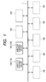
- the vehicle control system also employs a system which utilizes the time-synchronization network system to perform the so-called real-time control through a plurality of electronic control units on an in-vehicle network.
- the vehicle control system is provided with a plurality of electronic control units 100 including a throttle valve control device 110 for controlling the degree of opening of a throttle valve while measuring an amount of air sucked by an intake system (amount of intake air) of an internal combustion engine, and an injector control device 120 for controlling an amount of fuel, for example, injected by an injector while calculating an amount of fuel to be supplied (amount of fuel supply) to a combustion chamber of the internal combustion engine.
- a throttle valve control device 110 for controlling the degree of opening of a throttle valve while measuring an amount of air sucked by an intake system (amount of intake air) of an internal combustion engine
- an injector control device 120 for controlling an amount of fuel, for example, injected by an injector while calculating an amount of fuel to be supplied (amount of fuel supply) to a combustion chamber of the internal combustion engine.
- various types of vehicle data including an amount of intake air and an amount of fuel injection under monitoring are subjected to transmission/reception between the plurality of electronic control units 100.
- Various in-vehicle devices e.g., a throttle valve and an injector
- data indicative of freshness of such time-dependent data is also subjected transmission/reception between the plurality of electronic control units 100.
- validity of the time-dependent data is determined (determining means) based on the data indicative of freshness (hereinafter referred to as "freshness indicative data"). In this way, the vehicle control system is ensured to perform adequate control based on the result of the determination.
- time data which is indicative of the time of acquiring the time-dependent data and serving as the freshness indicative data
- use of the time data can cause an error in the subsequent determination as to the validity of the time-dependent data based on this time data, or moreover, can adversely effect the real-time control mentioned above.
- the vehicle control system is provided with time counting means for counting time from the point of acquiring the time-dependent data. Further, an arrangement is so made that the counted time (data freshness) provided by the counting means is used as the freshness indicative data and that the validity of the time-dependent data is determined based on the counted time. In this way, in case malfunction has occurred in the system, during which numerical values indicative of time of synchronization (counted value) are counted more than one round, the freshness (validity) of the time-dependent data used for the distributed control can be evaluated (determined) with higher reliability.
- Fig. 2A is a graph showing the counted time in the transmission-side electronic control unit 100 which transmits the freshness indicative data, relative to the real elapsed time from the point of acquiring the time-dependent data.
- Fig. 2B is a graph showing the counted time in the reception-side electronic control unit 100 which receives the freshness indicative data (time stamp), relative to the real elapsed time from the point of acquiring the time-dependent data.
- Fig. 2C is a block diagram illustrating a state where delay has occurred in the communication between the transmission-side electronic control unit 100 and the reception-side electronic control unit.
- a data indicative of elapse of "x" milliseconds from the acquisition of the time-independent data has been transmitted as the freshness indicative data from the transmission-side electronic control unit 100.
- delay of "2" milliseconds has occurred in the communication, the 2 milliseconds are not reflected as deterioration in the contents of the data to be transmitted, i.e. deterioration in the freshness of the time-dependent data.
- the reception-side electronic control unit 100 for receiving the freshness indicative data is to receive the data indicative of the lapse of only "x" milliseconds from the acquisition of the time-dependent data, at a point of time when "x+2" milliseconds have passed since the acquisition of the time-dependent data.
- the distributed control of the in-vehicle devices is performed by the transmission-side electronic control unit 100 and the reception-side electronic control unit 100 based on the data described above, inconsistency may occur in the control of the apparatuses, or moreover, the adequacy of the distributed control may be adversely effected.
- the vehicle control system is so arranged that time data (time stamp) indicative of the time of acquisition of the time-dependent data is used as the freshness indicative data, and that transmission/reception of the time data is performed with other electronic control unit through an in-vehicle network 1.
- time data time stamp
- transmission/reception of the time data is performed with other electronic control unit through an in-vehicle network 1.
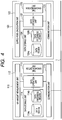
- Fig. 4 is a block diagram functionally illustrating an internal structure of the throttle valve control device 110 and the injector control device 120, in particular, among the electronic control units 100 illustrated in Fig. 1 .
- these control devices 110 and 120 not only perform the measuring process for the amount of intake air, but also perform control of the opening degree of the throttle valve, control of the fuel injection amount or the like of the injector, and control of the various in-vehicle devices.
- indication related to such distributed control is omitted from the figure to focus explanation on various operations associated with the freshness indicative data and administration of the freshness indicative data.
- throttle valve control device 110 is intended herein to serve as a transmission-side electronic control unit for transmitting the time-dependent data and the freshness indicative data for the time-independent data
- injector control device 120 is intended herein to serve as a reception-side electronic control unit.
- the air-amount measurement unit 112 measures, for example, an amount of air sucked to an intake system (hereinafter referred to as "intake amount") of an internal combustion engine such as through an airflow sensor and demands the data operation unit 111 to register the measured intake amount at the data storage portion 114.
- the data operation unit 111 stores the time-dependent data (intake amount herein) and the freshness indicative data of the time-dependent data in the data storage unit 114 in response to such a demand for registration.
- the time synchronization unit 113 displays time, which is in synchronization with other electronic control units on the in-vehicle network 1, in the form of a properly counted value such as by a counter, for example.
- the data storage unit 114 i.e.
- the memory such as RAM
- the intake amount i.e. the time-dependent data
- data freshness i.e. time from the point of acquiring the intake amount
- the communication unit 115 transmits/receives the time-dependent data, such as the intake amount, and the data indicative of the time of acquisition of the time-dependent data to/from other electronic control units through the in-vehicle network 1.
- the reception-side injector control device 120 is dominantly made up of a data operation unit 121 such as for controlling and administering the time-dependent data and the freshness indicative data for the time-dependent data which are used for the distributed control described above.
- the data operation unit 121 transmits/receives various data to/from a supply-fuel calculation unit 122, a time synchronization unit 123, a data storage unit 124 and a communication unit 125, for example.
- the supply-fuel calculation unit 122 demands, for example, the data operation unit 121 to acquire the intake amount registered at the data storage unit 124, and calculates a supply-fuel amount appropriate for realizing a targeted air-fuel ratio taking into account a relation, for example, with the acquired intake amount. In particular, the supply-fuel amount calculated in this way is used such as for the control of fuel injection amount by the injector.
- the time synchronization unit 123 displays time, which is synchronization with other electronic control units on the in-vehicle network 1, in the form of a properly counted value such as by a counter, for example.
- the data storage unit 124 i.e. memory such as RAM
- the data storage unit 124 includes a data region 124a and a data freshness region 124b.
- the supply-fuel amount calculated by the supply-fuel calculation unit 122 and the intake amount transmitted from the throttle valve control device 110, i.e. the time-dependent data, are registered at the data region 124a, and the data freshness is registered at the data freshness region 124b.
- the communication unit 125 transmits/receives the time-dependent data, such as the intake amount, and the data indicative of the time of acquisition of the time-dependent data to/from other electronic control units through the in-vehicle network 1.
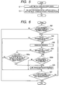
- Fig. 5 is a flow diagram illustrating a procedure of control performed by the data operation unit 111 in the transmission-side throttle valve control device 110 for transmitting the freshness indicative data, when there is a demand for registering the measured intake amount at the data storage unit 114.
- the data operation unit 111 when the intake amount is newly measured by the air-amount measurement unit 112 and the data operation unit 111 is demanded to register the measured intake amount at the data storage unit 114, the data operation unit 111 firstly stores, as shown at step S11 of Fig. 5 , the demanded intake amount (time-dependent data) in the data region 114a of the data storage unit 114. After registering the intake amount (time-dependent data) at the data storage unit 114, the data operation unit 111 then stores, at step S12, data freshness (counted time) for the intake amount at the data freshness region 114b of the data storage unit 114 in order to count time from the point of registration. In this case, the value of the data freshness is registered as "0".
- Fig. 6 is a flow diagram illustrating a procedure of control for renewing the data freshness, i.e. the counted time, stored in the data freshness region 114b. This control is periodically performed by the data operation unit 111 based such as on the time displayed by the time synchronization unit 113, for example.
- step S22 it is determined whether or not an invalid value is labeled on the data freshness of the time-dependent data, such as the measured intake amount.
- the data freshness is adapted to be labeled with a predetermined invalid value as a value indicative of invalidity of the data freshness. Accordingly, when the data freshness of the time-dependent data of interest is determined, at step S22, as being labeled with the invalid value, control proceeds to step S27 (explained later) without renewing the data freshness.
- step S23 the data freshness is renewed in a manner of counting up its value. In other words, time is counted from when the intake amount has been registered at the data storage unit 114 (or when the intake amount has been acquired). This counting is continued at intervals as long as the conditions at steps S21 and S22 are maintained.
- steps S24 to S26 a determination is made as to whether or not an invalid value should be labeled on the renewed data freshness, and the control based on the determination is performed.
- the time-dependent data such as the intake amount
- the time-dependent data is determined as to whether or not a valid term has been set at the data.
- control proceeds to step S25a.
- step S25a it is determined whether or not a counted value of the renewed data freshness exceeds a value of time critical to serving as the freshness indicative data. If the counted value is determined as exceeding the value of the time critical to serving as the freshness indicative data, or, for example, if the counted value of the data freshness has been counted up to a maximum count value, the counted value is labeled with the predetermined invalid value indicative of invalidity of the data freshness (step S26).
- step S27 (explained later). Contrarily, if it is determined, at step S25a, that the counted value does not exceed the value of the time critical to serving as the freshness indicative data, control proceeds to step S27 (explained later) without executing the process of step S26.
- step S24 when the time-dependent data, such as the intake amount, is determined as being set with the valid term, at step S24, control proceeds to step S25b, At step S25b, a determination is made as to whether or not the counted value of the data freshness stored in the data freshness region 114b exceeds a value of the valid term of the data freshness.
- the valid term of the data freshness is set at a value smaller than the value of the time critical to its serving as the freshness indicative data. If the counted value is determined as exceeding the value of the valid term, the predetermined invalid value indicative of invalidity is labeled on the counted value of the data freshness (step S26). Control then proceeds to step S27 (explained later). Contrarily, if it is determined, at step 525b, that the counted value does not exceed the value of the valid term, control proceeds to step S27 (explained later) without executing the process of step S26.
- step S27 it is determined whether or not other time-dependent data imparted with data freshness is registered at the data region 114a than the time-dependent data of interest, such as the intake amount. As long as such other data is registered at the data region 114a of the data storage unit 114, steps S22 to S27 described above are repeatedly performed for the data freshness of the time-dependent data.
- the distributed control is performed in a synchronized manner by counting time from the point of acquiring the time-dependent data. To this end, determination on the validity can be made based on the counted time (data freshness). In other words, even when some malfunction has occurred in the vehicle control system, during which numerical values indicative of time of synchronization (counted value) are counted more than one round, the freshness (validity) of the time-dependent data used for the distributed control can be evaluated (determined) with higher reliability based on the counted time (data freshness).
- Fig. 7 is a flow diagram illustrating a procedure of communication control performed by the data operation unit (communication control means) 111 when the intake amount, or the time-dependent data, and the freshness indicative data of the time-dependent data are transmitted from the transmission-side throttle valve control device 110 to the reception-side injector control device 120.
- the procedure of the communication control is performed for a predetermined period of time, for example.
- step S31 the intake amount and the data freshness of the intake amount which are subjected to the communication are read out from the data region 114a and the data freshness region 114b of the data storage unit 114, respectively.
- current time is obtained from the time synchronization unit 113.
- step S32 the current time displayed by the time synchronization unit 113 is determined as to its correctness. This process is executed, for example, as a process for determining whether or not the time being displayed by the time synchronization unit 113 is renewed within a predetermined period of time.
- step S33a time data (time stamp) is prepared for indicating the time of acquisition of the intake amount.
- time data time stamp
- the data freshness stored in the data freshness region 114b namely the time passed from the point of acquiring the intake amount, is subtracted from the current time to obtain the time of acquisition of the intake amount.
- the time data subjected to communication is prepared based on thus calculated time of acquisition of the intake amount.
- the time data prepared in this way is transmitted, at step S34, together with the intake amount to the reception-side injector control device 120 through the communication unit 115.
- the current time displayed by the time synchronization unit 113 may be determined as being incorrect.
- a predetermined invalid value is labeled on the time of acquisition of the intake amount so as to indicate invalidity of the time, and then the time data (time stamp) for communication is prepared based on the invalidity-labeled time of acquisition.
- the time data prepared in this way, together with the intake amount, is then transmitted to the reception-side injector control device 120 through the communication unit 115 (step S34).
- Fig. 8 is a flow diagram illustrating a procedure of communication control performed by the data operation unit (communication means) 121 of the reception-side injector control device 120 when the intake amount and the time data (time stamp) transmitted as described above are received by the injector control device 120.
- the procedure for the communication control is described below.
- step S41 current time is obtained from the time synchronization unit 123.
- step S42 it is determined as to whether or not the time indicated by the received time data (time stamp) is labeled with an invalid value.
- the current time displayed by the reception-side time synchronization unit 123 is also determined as to its correctness. Similar to the procedure of Fig. 7 , this process is executed, for example, as a process for determining whether or not the time displayed by the time synchronization unit 123 is renewed within a predetermined period of time.
- a process is performed for calculating time from when the intake amount has been stored (acquired) in the transmission-side storage unit 114 (data freshness).
- the data freshness is obtained by subtracting the acquisition time of the intake amount indicated by the time stamp, or the time data, from the current time (subtracted value).
- an example can be provided as follows.
- the time factors can be obtained such that the current time Time is 7 ms and the time data (time stamp) TS is 2 ms.
- the data freshness Frs becomes 5 ms.
- values of the data freshness Frs on both the transmission and reception sides at the time instant when the data is received by the control device 120 become equal to each other, when there occurs a delay of 2 ms in the communication. This means that the synchronization at to the data freshness is achieved on both transmission and reception sides at each current time.
- a vehicle control system and electronic control units used for the system according to a second embodiment of the present invention.
- the identical or similar components to those in the first embodiment are given the same references for the sake of simplification or omission of explanation.
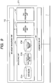
- the throttle valve control device 210 of the present embodiment is also dominantly made up of the data operation unit 111 for operating and administering the time-dependent data and the freshness indicative data of the time-independent data, which are used for the distributed control. Similar to the first embodiment, the data operation unit 111 transmits/receives these data to/from the air-amount measurement unit 112, the time synchronization unit 113, a data storage unit (memory means) 214 and the communication unit 115, for example. Among them, the data storage unit 214 of the present embodiment has the following three storage data regions 214a, 214b and 214c:
- the data operation unit 111 firstly stores (step Sill) the demanded intake amount (time-dependent data) in the data region 214a of the data storage unit 214. Then, after registering the intake amount (time-dependent data) at the data storage unit 214, the data freshness of the intake amount is stored in the data freshness region 214b of the data storage unit 214 in order to count time from the point of the registration (step S112).
- the time displayed by the time synchronization unit 113 is stored in the time stamp region 214c when the intake amount is registered in the data storage unit 214 (or when the intake amount is acquired). Accordingly, the time stored in the time stamp region 214c can be read out (step S131) for transmission as the time data (time stamp) (step S132).
- the process for obtaining the time data (time stamp) is more simplified, and thus a smooth process can be expected in the communication of the time data.
Landscapes
- Engineering & Computer Science (AREA)
- Automation & Control Theory (AREA)
- Mechanical Engineering (AREA)
- Computer Networks & Wireless Communication (AREA)
- Signal Processing (AREA)
- Combined Controls Of Internal Combustion Engines (AREA)
- Electric Clocks (AREA)
Claims (21)
- Elektronische Steuerungseinheit (110, 120) zum Steuern von fahrzeugeigenen Vorrichtungen unter Verwendung von zeitabhängigen Daten als jeweilige elektronische Steuerungen, die ein System zum Steuern von fahrzeugeigenen Vorrichtungen auf verteilte und synchronisierte Steuerungsweise in einem Fahrzeug bilden, wobei die elektronischen Steuerungseinheiten (110, 120) kommunizierbar über ein fahrzeugeigenes Netzwerk (1) miteinander verbunden sind, um Informationen, die zeitabhängige Daten enthalten, unter den elektronischen Steuerungseinheiten (110, 120) zu kommunizieren, wobei die elektronische Steuerungseinheit (110, 120) aufweist:eine Messeinheit (112, 122) zum Messen von zeitabhängigen Daten;ein Steuerungselement, das die Steuerung auf der Grundlage der zeitabhängigen Daten durchführt;eine Datenspeichereinheit (114, 124) zum Registrieren der gemessenen zeitabhängigen Daten;eine Zeitsynchronisationseinheit (112, 123); undeine Kommunikationseinheit (115, 125);gekennzeichnet durch:eine Datenbetriebseinheit (111, 121) zum Steuern und Verwalten der zeitabhängigen Daten und eine Frische angebenden Daten für die zeitabhängigen Daten;wobei die Datenbetriebseinheit (111, 121) als eine Verstrichene-Zeit-Berechnungskomponente (111, 121) ausgelegt ist, die ausgelegt ist, einen Wert von eine Frische angebenden Daten, die eine Frische der erlangten Daten angeben, als 0 in der Datenspeichereinheit (114, 124) zu registrieren, wenn die zeitabhängigen Daten in der Datenspeichereinheit (114, 124) registriert werden, und den Wert der eine Frische angebenden Daten aufwärts zu zählen, um eine verstrichene Zeit zu berechnen, die seit der Erlangung der zeitabhängigen Daten verstrichen ist; undwobei die Datenbetriebseinheit (111, 121) als eine Gültigkeitsbestimmungskomponente (111, 121) ausgelegt ist, die ausgelegt ist, die berechnete verstrichene Zeit zu verwenden, um zu bestimmen, ob die zeitabhängigen Daten für die Steuerung hinsichtlich der Frische der zeitabhängigen Daten gültig sind.
- Elektronische Steuerungseinheit (110, 120) nach Anspruch 1, wobei die Verstrichene-Zeit-Berechnungskomponente (111, 121) ausgelegt ist, die verstrichene Zeit durch Aufwärtszählen der Zeit in Intervallen zu berechnen, wann immer die zeitabhängigen Daten erlangt werden.
- Elektronische Steuerungseinheit (110, 120) nach Anspruch 1, die aufweist:eine Produktionskomponente (111, 121), die als Informationen, die die Frische der zeitabhängigen Daten angeben, Daten produziert, die einen Zeitmoment zeigen, zu dem die zeitabhängigen Daten erlangt wurden; undeine Übertragungskomponente (115, 125), die die zeitabhängigen Daten und die Daten, die den Zeitmoment der Datenerlangung zeigen, an eine andere elektronische Steuerungseinheit (110, 120) über das fahrzeugeigene Netzwerk (1) überträgt.
- Elektronische Steuerungseinheit (110, 120) nach Anspruch 3, wobei die Produktionskomponente (111, 121) eine Einrichtung zum Erhalten eines derzeitigen Moments, zu dem die zeitabhängigen Daten übertragen werden, und eine Einrichtung zum Berechnen der Daten, die den Zeitmoment der Datenerlangung zeigen, durch Subtrahieren der berechneten verstrichenen Zeit von dem derzeitigen Zeitmoment der Übertragung aufweist.
- Elektronische Steuerungseinheit (110, 120) nach Anspruch 4, wobei die Gültigkeitsbestimmungskomponente (111, 121) aufweist:eine Derzeitige-Zeit-Bestimmungskomponente (111, 121), die bestimmt, ob der derzeitige Zeitmoment normal ist, wenn die Übertragung durchgeführt wird; undeine Einstellkomponente (111, 121), die einen Ungültigkeitswert für die Daten einstellt, die den Zeitmoment der Datenerlangung zeigen, wenn bestimmt wird, dass der derzeitige Zeitmoment nicht normal ist.
- Elektronische Steuerungseinheit (110, 120) nach Anspruch 5, wobei
die zeitabhängigen Daten in der Datenspeichereinheit (114, 124) zusammen mit den Daten gespeichert werden, die den Zeitmoment zeigen, zu dem die zeitabhängigen Daten erlangt wurden,
wobei die Einstellkomponente (111, 121) ausgelegt ist, Bezug auf die Datenspeichereinheit (114, 124) zu nehmen, um den Zeitmoment der Datenerlangung zu erhalten. - Elektronische Steuerungseinheit (110, 120) nach Anspruch 3, die aufweist:eine Empfangskomponente (115), die die zeitabhängigen Daten und die Daten, die den Zeitmoment der Datenerlangung zeigen, von einer anderen elektronischen Steuerungseinheit über das fahrzeugeigene Netzwerk (1) empfängt; undeine weitere Verstrichene-Zeit-Berechnungskomponente (111, 121), die ausgelegt ist, eine verstrichene Zeit, die seit der Erlangung der empfangenen zeitabhängigen Daten verstrichen ist, auf der Grundlage der Daten, die den Zeitmoment der Datenerlangung zeigen, und eines derzeitigen Zeitmoments zu berechnen, zu dem die zeitabhängigen Daten durch die Empfangskomponente (115) empfangen werden, wobei die berechnete verstrichene Zeit für die Gültigkeitsbestimmungskomponente (111, 121) bereitgestellt wird.
- Elektronische Steuerungseinheit nach Anspruch 7, wobei die weitere Verstrichene-Zeit-Berechnungskomponente (111, 121) aufweist:eine Einrichtung zum Erhalten des derzeitigen Zeitmoments, zu dem die zeitabhängigen Daten empfangen werden, undeine Einrichtung zum Berechnen der verstrichenen Zeit, die seit der Erlangung der empfangenen zeitabhängigen Daten verstrichen ist, durch Subtrahieren des Zeitmoments der Erlangung der empfangenen zeitabhängigen Daten von dem derzeitigen Zeitmoment des Empfangs.
- Elektronische Steuerungseinheit nach einem der Ansprüche 3 und 8, wobei die Gültigkeitsbestimmungskomponente (111, 121) aufweist:eine Einrichtung zum Bestimmen, ob die berechnete verstrichene Zeit ihre Ungültigkeit zeigt,eine Einrichtung zum Bestimmen, dass die zeitabhängigen Daten für die Steuerung ungültig sind, wann immer bestimmt wird, dass die berechnete verstrichene Zeit ihre Ungültigkeit zeigt,eine Einrichtung zum Einstellen eines Ungültigkeitswerts für die berechnete verstrichene Zeit.
- Elektronische Steuerungseinheit nach Anspruch 9, wobei die Gültigkeitsbestimmungskomponente (111, 121) eine Einrichtung zum Aufzeichnen der Daten aufweist, die die Ungültigkeit zeigen, wenn die berechnete verstrichene Zeit eine Grenzzeit überschreitet, die einem maximalen Ausdruck der Informationen entspricht, die die Frische der zeitabhängigen Daten angeben.
- Elektronische Steuerungseinheit nach Anspruch 9, wobei die Gültigkeitsbestimmungskomponente (111, 121) eine Einrichtung zum Aufzeichnen der Daten aufweist, die die Ungültigkeit zeigen, wenn die berechnete verstrichene Zeit eine Gültigkeitsfrist überschreitet, die für eine Garantie der Gültigkeit der zeitabhängigen Daten eingestellt ist.
- Elektronische Steuerungseinheit nach Anspruch 9, wobei die Gültigkeitsbestimmungskomponente (111, 121) enthält:eine Einrichtung zum Bestimmen, ob es eine eingestellte Gültigkeitsfrist für die berechnete verstrichene Zeit gibt;eine Einrichtung zum Bestimmen, ob die berechnete verstrichene Zeit eine Grenzzeit überschreitet, die einem maximalen Ausdruck der Informationen entspricht, die die Frische der zeitabhängigen Daten angeben, wenn bestimmt wird, dass die Gültigkeitsfrist nicht eingestellt ist;eine Einrichtung zum Aufzeichnen der Daten, die die Ungültigkeit zeigen, wann immer die berechnete verstrichene Zeit die Grenzzeit überschreitet;eine Einrichtung zum Bestimmen, ob die berechnete verstrichene Zeit die Gültigkeitsfrist überschritten hat, wenn bestimmt wird, dass die Gültigkeitsfrist eingestellt ist; undeine Einrichtung zum Aufzeichnen der Daten, die die Ungültigkeit zeigen, wann immer die berechnete verstrichene Zeit die Gültigkeitsfrist überschritten hat.
- Elektronische Steuerungseinheit nach Anspruch 8, wobei die Gültigkeitsbestimmungskomponente (111, 121) enthält:eine Einrichtung zum Bestimmen, ob der derzeitige Zeitmoment normal ist, wenn der Empfang durchgeführt wird;eine Einrichtung zum Bestimmen, ob die empfangenen Daten, die den Zeitmoment der Datenerlangung zeigen, ihre Gültigkeit zeigen; undeine Einrichtung zum Einstellen eines Ungültigkeitswerts für die berechnete verstrichene Zeit, wenn bestimmt wird, dass der derzeitige Zeitmoment normal ist und/oder der Zeitmoment der Datenerlangung nicht seine Gültigkeit zeigt.
- System zum Steuern von fahrzeugeigenen Vorrichtungen auf verteilte und synchronisierte Steuerungsweise in einem Fahrzeug, wobei das System aufweist:mehrere elektronische Steuerungseinheiten (110, 120), die für ein Steuern von Betrieben der fahrzeugeigenen Vorrichtungen auf der Grundlage von zeitabhängigen Daten zuständig sind, die in einer Zeitfolge betreffend das Fahrzeug erlangt werden; undein fahrzeugeigenes Netzwerk (1), das kommunizierbar die elektronischen Steuerungseinheiten (110, 120) miteinander verbindet, um Informationen, die die zeitabhängigen Daten enthalten, unter den elektronischen Steuerungseinheiten (110, 120) zu kommunizieren,wobei jede der elektronischen Steuerungseinheiten (110, 120) aufweist:eine Messeinheit (112, 122) zum Messen der zeitabhängigen Daten;ein Steuerungselement, das die Steuerung auf der Grundlage der zeitabhängigen Daten durchführt; undeine Datenspeichereinheit (114, 124) zum Registrieren der gemessenen zeitabhängigen Daten;eine Zeitsynchronisationseinheit (112, 123); und
eine Kommunikationseinheit (115, 125);
dadurch gekennzeichnet, dass jede der elektronischen Steuerungseinheiten (110, 120) außerdem aufweist:eine Datenbetriebseinheit (111, 121) zum Steuern und Verwalten der zeitabhängigen Daten und von eine Frische angebenden Daten für die zeitabhängigen Daten;wobei die Datenbetriebseinheit (111, 121) als eine Verstrichene-Zeit-Berechnungskomponente (111, 121) ausgelegt ist, die ausgelegt ist, einen Wert von eine Frische angebenden Daten, die eine Frische der erlangten Daten angeben, als 0 in der Datenspeichereinheit (114, 124) zu registrieren, wenn die zeitabhängigen Daten in der Datenspeichereinheit (114, 124) registriert werden, und einen Wert der eine Frische angebenden Daten aufwärts zu zählen, um eine verstrichene Zeit zu berechnen, die seit einer Erlangung der zeitabhängigen Daten verstrichen ist; undwobei die Datenbetriebseinheit (111, 121) als eine Gültigkeitsbestimmungskomponente (111, 121) ausgelegt ist, die ausgelegt ist, die berechnete verstrichene Zeit zu verwenden, um zu bestimmen, ob die zeitabhängigen Daten für die Steuerung hinsichtlich der Frische der zeitabhängigen Daten gültig sind. - Elektronische Steuerungseinheit nach Anspruch 14, wobei die Verstrichene-Zeit-Berechnungskomponente (111, 121) ausgelegt ist, die verstrichene Zeit durch Aufwärtszählen einer Zeit in Intervallen, wann immer die zeitabhängigen Daten erlangt werden, zu berechnen.
- System nach Anspruch 15, wobei jede der elektronischen Steuerungseinheiten (110, 120) aufweist:eine Produktionskomponente (111, 121), die als Informationen, die die Frische der zeitabhängigen Daten angeben, Daten produziert, die einen Zeitmoment zeigen, zu dem die zeitabhängigen Daten erlangt wurden, undeine Übertragungskomponente (115, 125), die die zeitabhängigen Daten und die Daten, die den Zeitmoment der Datenerlangung zeigen, an eine andere elektronische Steuerungseinheit über das fahrzeugeigene Netzwerk (1) überträgt.
- System nach Anspruch 16, wobei die Produktionskomponente (111, 121) eine Einrichtung zum Erhalten eines derzeitigen Zeitmoments, zu dem die zeitabhängigen Daten übertragen werden, und eine Einrichtung zum Berechnen der Daten, die den Zeitmoment der Datenerlangung zeigen, durch Subtrahieren der berechneten verstrichenen Zeit von dem derzeitigen Zeitmoment der Übertragung aufweist.
- System nach Anspruch 17, wobei die Gültigkeitsbestimmungskomponente (111, 121) aufweist:eine Derzeitige-Zeit-Bestimmungskomponente (111, 121), die bestimmt, ob der derzeitige Zeitmoment normal ist, wenn die Übertragung durchgeführt wird; undeine Einstellkomponente (111, 121), die einen Ungültigkeitswert für die Daten einstellt, die den Zeitmoment der Datenerlangung zeigen, wenn bestimmt wird, dass der derzeitige Zeitmoment nicht normal ist.
- System nach Anspruch 16, wobei jede der elektronischen Steuerungseinheiten (110, 120) aufweist:eine Empfangskomponente (115), die die zeitabhängigen Daten und die Daten, die den Zeitmoment der Datenerlangung zeigen, von einer anderen elektronischen Steuerungseinheit über das fahrzeugeigene Netzwerk (1) empfängt; undeine weitere Verstrichene-Zeit-Berechnungskomponente (111, 121), die ausgelegt ist, eine verstrichene Zeit, die seit der Erlangung der empfangenen zeitabhängigen Daten verstrichen ist, auf der Grundlage der Daten, die den Zeitmoment der Datenerlangung zeigen, und eines derzeitigen Zeitmoments, zu dem die zeitabhängigen Daten durch die Empfangskomponente (115) empfangen werden, zu berechnen.
- System nach Anspruch 19, wobei die weitere Verstrichene-Zeit-Berechnungskomponente (111, 121) aufweist:eine Einrichtung zum Erhalten des derzeitigen Zeitmoments, zu dem die zeitabhängigen Daten empfangen werden, undeine Einrichtung zum Berechnen der verstrichenen Zeit, die seit der Erlangung der empfangenen zeitabhängigen Daten verstrichen ist, durch Subtrahieren des Zeitmoments der Erlangung der empfangenen zeitabhängigen Daten von dem derzeitigen Zeitmoment des Empfangs.
- System nach Anspruch 20, wobei die Gültigkeitsbestimmungskomponente (111, 121) enthält:eine Einrichtung zum Bestimmen, ob der derzeitige Zeitmoment normal ist, wenn der Empfang durchgeführt wird;eine Einrichtung zum Bestimmen, ob die empfangenen Daten, die den Zeitmoment der Datenerlangung zeigen, ihre Gültigkeit zeigen; undeine Einrichtung zum Einstellen eines Ungültigkeitswerts für die berechnete verstrichene Zeit, wenn bestimmt wird, dass der derzeitige Zeitmoment normal ist und/oder der Zeitmoment der Datenerlangung seine Gültigkeit nicht zeigt.
Applications Claiming Priority (1)
| Application Number | Priority Date | Filing Date | Title |
|---|---|---|---|
| JP2006067202A JP4437795B2 (ja) | 2006-03-13 | 2006-03-13 | 車両制御システム及び電子制御装置 |
Publications (2)
| Publication Number | Publication Date |
|---|---|
| EP1834840A1 EP1834840A1 (de) | 2007-09-19 |
| EP1834840B1 true EP1834840B1 (de) | 2018-12-05 |
Family
ID=38198465
Family Applications (1)
| Application Number | Title | Priority Date | Filing Date |
|---|---|---|---|
| EP07005174.3A Ceased EP1834840B1 (de) | 2006-03-13 | 2007-03-13 | Elektronische Steuereinheiten zur Steuerung in Fahrzeugen unter Verwendung von zeitabhängigen Daten und Fahrzeugsteuersystem mit derartigen Einheiten für verteilte Echtzeit-Steuerung |
Country Status (3)
| Country | Link |
|---|---|
| US (1) | US8010257B2 (de) |
| EP (1) | EP1834840B1 (de) |
| JP (1) | JP4437795B2 (de) |
Families Citing this family (10)
| Publication number | Priority date | Publication date | Assignee | Title |
|---|---|---|---|---|
| JP5165957B2 (ja) * | 2007-08-03 | 2013-03-21 | 株式会社オートネットワーク技術研究所 | 車載通信システム |
| KR101428093B1 (ko) | 2008-09-08 | 2014-08-08 | 현대자동차주식회사 | 차량 네트워크에서의 데이터 유효성 진단 장치 |
| CN104199335A (zh) * | 2014-07-23 | 2014-12-10 | 小米科技有限责任公司 | 一种发送、接收物品信息的方法和装置 |
| CN106904133B (zh) * | 2017-01-22 | 2022-03-08 | 斑马信息科技有限公司 | 汽车时间系统及其时间控制方法和控制系统 |
| EP3546355B1 (de) * | 2018-03-29 | 2021-07-07 | Airbus Operations GmbH | Flugzeugbereich mit einer textilanzeige, und ein flugzeug mit einem solchen flugzeugbereich |
| US11560240B2 (en) | 2018-03-29 | 2023-01-24 | Airbus Operations Gmbh | Aircraft area having a textile display, aircraft passenger seat having a textile display, and aircraft including an aircraft area |
| US10999216B2 (en) * | 2018-07-13 | 2021-05-04 | EMC IP Holding Company LLC | Resource allocation and provisioning in a multi-tier edge-cloud virtualization environment |
| JP7059959B2 (ja) * | 2019-02-12 | 2022-04-26 | トヨタ自動車株式会社 | 車載ネットワークシステム |
| US11323456B2 (en) * | 2020-01-06 | 2022-05-03 | Centurylink Intellectual Property Llc | Telemetry hub |
| CN120010431B (zh) * | 2024-10-08 | 2025-10-31 | 重庆赛力斯凤凰智创科技有限公司 | 车辆中受控器件故障检测方法、装置、计算机设备和介质 |
Family Cites Families (14)
| Publication number | Priority date | Publication date | Assignee | Title |
|---|---|---|---|---|
| EP0072000B1 (de) * | 1981-08-07 | 1988-10-19 | Nippondenso Co., Ltd. | System zur Fehlererkennung und -anzeige für Motorfahrzeuge |
| JPH11261611A (ja) | 1998-03-12 | 1999-09-24 | Mitsubishi Electric Corp | 送信用バスインタフェース装置 |
| US6065406A (en) * | 1998-06-24 | 2000-05-23 | Katzer; Matthew A. | Model train control system |
| US6998996B1 (en) * | 1998-12-03 | 2006-02-14 | Agilent Technologies, Inc. | Motion control using time synchronization |
| JP2001141508A (ja) | 1999-11-11 | 2001-05-25 | Yokogawa Electric Corp | 測定機器並びにデータ収集機器及びこれらを用いた測定システム |
| DE10218645A1 (de) | 2002-04-25 | 2003-11-13 | Infineon Technologies Ag | An einen Bus angeschlossene Einrichtung |
| JP2004085286A (ja) | 2002-08-26 | 2004-03-18 | Alpine Electronics Inc | 車載用ナビゲーション装置、ナビゲーション情報表示方法及びプログラム |
| JP2004220326A (ja) | 2003-01-15 | 2004-08-05 | Denso Corp | 制御ソフトウエア構造およびこの構造を用いた制御装置 |
| US20040260788A1 (en) * | 2003-05-30 | 2004-12-23 | Kazuhiko Miyano | Information provision system, terminal unit and relay unit forming part of that system, and image display customizing system |
| JP4237681B2 (ja) | 2003-09-12 | 2009-03-11 | 株式会社日本自動車部品総合研究所 | 情報放送装置 |
| JP4089620B2 (ja) * | 2004-01-15 | 2008-05-28 | 株式会社デンソー | 車両制御システム |
| JP4311210B2 (ja) | 2004-01-19 | 2009-08-12 | 株式会社デンソー | 車両リアルタイム制御システム、送信ecuおよび受信ecu |
| JP4509603B2 (ja) * | 2004-02-27 | 2010-07-21 | 富士重工業株式会社 | 制御ユニットおよびデータ送信方法 |
| JP4595637B2 (ja) | 2005-04-11 | 2010-12-08 | 株式会社デンソー | 車両用制御装置および車両用制御装置に用いるプログラム |
-
2006
- 2006-03-13 JP JP2006067202A patent/JP4437795B2/ja not_active Expired - Fee Related
-
2007
- 2007-03-13 US US11/717,179 patent/US8010257B2/en not_active Expired - Fee Related
- 2007-03-13 EP EP07005174.3A patent/EP1834840B1/de not_active Ceased
Non-Patent Citations (1)
| Title |
|---|
| None * |
Also Published As
| Publication number | Publication date |
|---|---|
| JP2007238044A (ja) | 2007-09-20 |
| JP4437795B2 (ja) | 2010-03-24 |
| EP1834840A1 (de) | 2007-09-19 |
| US20070213888A1 (en) | 2007-09-13 |
| US8010257B2 (en) | 2011-08-30 |
Similar Documents
| Publication | Publication Date | Title |
|---|---|---|
| EP1834840A1 (de) | Elektronische Steuereinheiten zur Steuerung in Fahrzeugen unter Verwendung von zeitabhängigen Daten und Fahrzeugsteuersystem mit derartigen Einheiten für verteilte Echtzeit-Steuerung | |
| US10169540B2 (en) | Blood glucose system having time synchronization | |
| US20090159132A1 (en) | Method for operating a metering valve and device for performing the method | |
| US9886800B2 (en) | Engine state detection device | |
| US9670858B2 (en) | Identification of air and/or fuel metering drift | |
| ES2629280T3 (es) | Sistema de gestión de la diabetes con registro del tiempo | |
| EP2859464A2 (de) | Beurteilung von elektronischen sensordaten zur entfernten identifizierung eines kraftfahrzeugs und zur überwachung des fahrverhaltens | |
| JP2008511373A (ja) | 体内物質の濃度を測定するためのシステムを較正する方法及びその方法を実行するための装置 | |
| EP3244199B1 (de) | Feuchtigkeitsmessvorrichtung | |
| US20130306034A1 (en) | Method and device for actuating an injector in a fuel injection system of an internal combustion engine | |
| JP5195472B2 (ja) | 車両用故障診断システム、車両用故障診断方法 | |
| JP5892112B2 (ja) | 電子制御装置 | |
| US11268464B2 (en) | Engine control unit (ECU) and method to adapt the ECU for trigger wheel irregularities | |
| CN103147866B (zh) | 用于内燃机的控制方法和系统 | |
| KR20160071980A (ko) | Obd2를 이용한 인젝터 진단 방법 및 장치 | |
| JP4952406B2 (ja) | 時刻補正方法、マイコン内部時計、電子制御ユニット | |
| US12286009B2 (en) | Vehicle fuel level estimation | |
| KR101544933B1 (ko) | 내연 엔진을 위한 작동 이벤트들의 제어 | |
| JP5295213B2 (ja) | 車両等の制御装置 | |
| JP4685610B2 (ja) | 車両等の制御装置 | |
| KR20120058044A (ko) | 전자제어장치의 캐패시터 불량 판독 시스템 및 이의 사용방법 | |
| JP2020091657A (ja) | 電子制御装置 | |
| JP2012002620A (ja) | 筒内圧力センサの校正装置 | |
| JP5868547B2 (ja) | 有利には内燃機関の燃焼室内に設けられた圧力センサの、センサ内に組み込まれた評価回路の出力信号のオフセットを算出するための方法及びセンサ | |
| RU2277298C1 (ru) | Устройство и способ (варианты) хронирования информации автономной информационно-измерительной системы |
Legal Events
| Date | Code | Title | Description |
|---|---|---|---|
| PUAI | Public reference made under article 153(3) epc to a published international application that has entered the european phase |
Free format text: ORIGINAL CODE: 0009012 |
|
| AK | Designated contracting states |
Kind code of ref document: A1 Designated state(s): AT BE BG CH CY CZ DE DK EE ES FI FR GB GR HU IE IS IT LI LT LU LV MC MT NL PL PT RO SE SI SK TR |
|
| AX | Request for extension of the european patent |
Extension state: AL BA HR MK YU |
|
| 17P | Request for examination filed |
Effective date: 20080319 |
|
| AKX | Designation fees paid |
Designated state(s): DE FR GB |
|
| 17Q | First examination report despatched |
Effective date: 20110630 |
|
| RAP1 | Party data changed (applicant data changed or rights of an application transferred) |
Owner name: TOYOTA JIDOSHA KABUSHIKI KAISHA Owner name: DENSO CORPORATION |
|
| REG | Reference to a national code |
Ref country code: DE Ref legal event code: R079 Ref document number: 602007057016 Country of ref document: DE Free format text: PREVIOUS MAIN CLASS: B60R0016020000 Ipc: B60R0016023000 |
|
| GRAP | Despatch of communication of intention to grant a patent |
Free format text: ORIGINAL CODE: EPIDOSNIGR1 |
|
| STAA | Information on the status of an ep patent application or granted ep patent |
Free format text: STATUS: GRANT OF PATENT IS INTENDED |
|
| RIC1 | Information provided on ipc code assigned before grant |
Ipc: B60R 16/023 20060101AFI20180517BHEP Ipc: H04J 3/06 20060101ALI20180517BHEP |
|
| INTG | Intention to grant announced |
Effective date: 20180619 |
|
| GRAS | Grant fee paid |
Free format text: ORIGINAL CODE: EPIDOSNIGR3 |
|
| GRAA | (expected) grant |
Free format text: ORIGINAL CODE: 0009210 |
|
| GRAA | (expected) grant |
Free format text: ORIGINAL CODE: 0009210 |
|
| STAA | Information on the status of an ep patent application or granted ep patent |
Free format text: STATUS: THE PATENT HAS BEEN GRANTED |
|
| AK | Designated contracting states |
Kind code of ref document: B1 Designated state(s): DE FR GB |
|
| REG | Reference to a national code |
Ref country code: GB Ref legal event code: FG4D |
|
| RIN1 | Information on inventor provided before grant (corrected) |
Inventor name: NODA, WAKA Inventor name: HIRANO, HIROYUKI Inventor name: ITO, RYO Inventor name: SHIDAI, TAKAHIRO Inventor name: MIYAMOTO, SEIJI |
|
| REG | Reference to a national code |
Ref country code: DE Ref legal event code: R096 Ref document number: 602007057016 Country of ref document: DE |
|
| REG | Reference to a national code |
Ref country code: DE Ref legal event code: R097 Ref document number: 602007057016 Country of ref document: DE |
|
| PLBE | No opposition filed within time limit |
Free format text: ORIGINAL CODE: 0009261 |
|
| STAA | Information on the status of an ep patent application or granted ep patent |
Free format text: STATUS: NO OPPOSITION FILED WITHIN TIME LIMIT |
|
| REG | Reference to a national code |
Ref country code: GB Ref legal event code: 746 Effective date: 20191010 |
|
| 26N | No opposition filed |
Effective date: 20190906 |
|
| REG | Reference to a national code |
Ref country code: DE Ref legal event code: R084 Ref document number: 602007057016 Country of ref document: DE |
|
| PGFP | Annual fee paid to national office [announced via postgrant information from national office to epo] |
Ref country code: GB Payment date: 20220321 Year of fee payment: 16 Ref country code: DE Payment date: 20220322 Year of fee payment: 16 |
|
| PGFP | Annual fee paid to national office [announced via postgrant information from national office to epo] |
Ref country code: FR Payment date: 20220322 Year of fee payment: 16 |
|
| REG | Reference to a national code |
Ref country code: DE Ref legal event code: R119 Ref document number: 602007057016 Country of ref document: DE |
|
| GBPC | Gb: european patent ceased through non-payment of renewal fee |
Effective date: 20230313 |
|
| PG25 | Lapsed in a contracting state [announced via postgrant information from national office to epo] |
Ref country code: GB Free format text: LAPSE BECAUSE OF NON-PAYMENT OF DUE FEES Effective date: 20230313 |
|
| PG25 | Lapsed in a contracting state [announced via postgrant information from national office to epo] |
Ref country code: GB Free format text: LAPSE BECAUSE OF NON-PAYMENT OF DUE FEES Effective date: 20230313 Ref country code: FR Free format text: LAPSE BECAUSE OF NON-PAYMENT OF DUE FEES Effective date: 20230331 Ref country code: DE Free format text: LAPSE BECAUSE OF NON-PAYMENT OF DUE FEES Effective date: 20231003 |