EP1831476B1 - Lochplatte auf basis von gips - Google Patents
Lochplatte auf basis von gips Download PDFInfo
- Publication number
- EP1831476B1 EP1831476B1 EP05850485A EP05850485A EP1831476B1 EP 1831476 B1 EP1831476 B1 EP 1831476B1 EP 05850485 A EP05850485 A EP 05850485A EP 05850485 A EP05850485 A EP 05850485A EP 1831476 B1 EP1831476 B1 EP 1831476B1
- Authority
- EP
- European Patent Office
- Prior art keywords
- gypsum
- shiplap
- perforated board
- based perforated
- board
- Prior art date
- Legal status (The legal status is an assumption and is not a legal conclusion. Google has not performed a legal analysis and makes no representation as to the accuracy of the status listed.)
- Revoked
Links
- 239000011505 plaster Substances 0.000 title abstract description 3
- 229910052602 gypsum Inorganic materials 0.000 claims description 35
- 239000010440 gypsum Substances 0.000 claims description 35
- 239000000463 material Substances 0.000 claims description 23
- 238000000034 method Methods 0.000 claims description 10
- 239000000945 filler Substances 0.000 claims description 7
- 238000005520 cutting process Methods 0.000 claims description 5
- 238000004519 manufacturing process Methods 0.000 claims description 3
- 239000000203 mixture Substances 0.000 claims description 3
- 239000003522 acrylic cement Substances 0.000 claims description 2
- 239000006185 dispersion Substances 0.000 claims description 2
- 239000011507 gypsum plaster Substances 0.000 claims 1
- 238000004080 punching Methods 0.000 claims 1
- 238000009434 installation Methods 0.000 description 5
- 239000002184 metal Substances 0.000 description 4
- 239000000853 adhesive Substances 0.000 description 2
- 230000001070 adhesive effect Effects 0.000 description 2
- 238000010276 construction Methods 0.000 description 2
- 208000018459 dissociative disease Diseases 0.000 description 2
- 229910052500 inorganic mineral Inorganic materials 0.000 description 2
- 239000011707 mineral Substances 0.000 description 2
- 230000007704 transition Effects 0.000 description 2
- 230000000007 visual effect Effects 0.000 description 2
- 241001441723 Takifugu Species 0.000 description 1
- 239000011358 absorbing material Substances 0.000 description 1
- NIXOWILDQLNWCW-UHFFFAOYSA-N acrylic acid group Chemical group C(C=C)(=O)O NIXOWILDQLNWCW-UHFFFAOYSA-N 0.000 description 1
- 230000001680 brushing effect Effects 0.000 description 1
- 238000005253 cladding Methods 0.000 description 1
- 239000002131 composite material Substances 0.000 description 1
- 230000000694 effects Effects 0.000 description 1
- 239000000835 fiber Substances 0.000 description 1
- 239000003292 glue Substances 0.000 description 1
- 210000004209 hair Anatomy 0.000 description 1
- 230000001788 irregular Effects 0.000 description 1
- 238000003801 milling Methods 0.000 description 1
- 239000011490 mineral wool Substances 0.000 description 1
- 239000004745 nonwoven fabric Substances 0.000 description 1
- 238000002360 preparation method Methods 0.000 description 1
- 230000002787 reinforcement Effects 0.000 description 1
- 238000010561 standard procedure Methods 0.000 description 1
- 239000000725 suspension Substances 0.000 description 1
Images

Classifications
-
- E—FIXED CONSTRUCTIONS
- E04—BUILDING
- E04C—STRUCTURAL ELEMENTS; BUILDING MATERIALS
- E04C2/00—Building elements of relatively thin form for the construction of parts of buildings, e.g. sheet materials, slabs, or panels
- E04C2/02—Building elements of relatively thin form for the construction of parts of buildings, e.g. sheet materials, slabs, or panels characterised by specified materials
- E04C2/04—Building elements of relatively thin form for the construction of parts of buildings, e.g. sheet materials, slabs, or panels characterised by specified materials of concrete or other stone-like material; of asbestos cement; of cement and other mineral fibres
- E04C2/043—Building elements of relatively thin form for the construction of parts of buildings, e.g. sheet materials, slabs, or panels characterised by specified materials of concrete or other stone-like material; of asbestos cement; of cement and other mineral fibres of plaster
-
- E—FIXED CONSTRUCTIONS
- E04—BUILDING
- E04B—GENERAL BUILDING CONSTRUCTIONS; WALLS, e.g. PARTITIONS; ROOFS; FLOORS; CEILINGS; INSULATION OR OTHER PROTECTION OF BUILDINGS
- E04B1/00—Constructions in general; Structures which are not restricted either to walls, e.g. partitions, or floors or ceilings or roofs
- E04B1/62—Insulation or other protection; Elements or use of specified material therefor
- E04B1/74—Heat, sound or noise insulation, absorption, or reflection; Other building methods affording favourable thermal or acoustical conditions, e.g. accumulating of heat within walls
- E04B1/82—Heat, sound or noise insulation, absorption, or reflection; Other building methods affording favourable thermal or acoustical conditions, e.g. accumulating of heat within walls specifically with respect to sound only
- E04B1/84—Sound-absorbing elements
- E04B1/86—Sound-absorbing elements slab-shaped
-
- E—FIXED CONSTRUCTIONS
- E04—BUILDING
- E04B—GENERAL BUILDING CONSTRUCTIONS; WALLS, e.g. PARTITIONS; ROOFS; FLOORS; CEILINGS; INSULATION OR OTHER PROTECTION OF BUILDINGS
- E04B9/00—Ceilings; Construction of ceilings, e.g. false ceilings; Ceiling construction with regard to insulation
- E04B9/001—Ceilings; Construction of ceilings, e.g. false ceilings; Ceiling construction with regard to insulation characterised by provisions for heat or sound insulation
-
- E—FIXED CONSTRUCTIONS
- E04—BUILDING
- E04B—GENERAL BUILDING CONSTRUCTIONS; WALLS, e.g. PARTITIONS; ROOFS; FLOORS; CEILINGS; INSULATION OR OTHER PROTECTION OF BUILDINGS
- E04B9/00—Ceilings; Construction of ceilings, e.g. false ceilings; Ceiling construction with regard to insulation
- E04B9/04—Ceilings; Construction of ceilings, e.g. false ceilings; Ceiling construction with regard to insulation comprising slabs, panels, sheets or the like
- E04B9/0435—Ceilings; Construction of ceilings, e.g. false ceilings; Ceiling construction with regard to insulation comprising slabs, panels, sheets or the like having connection means at the edges
-
- E—FIXED CONSTRUCTIONS
- E04—BUILDING
- E04B—GENERAL BUILDING CONSTRUCTIONS; WALLS, e.g. PARTITIONS; ROOFS; FLOORS; CEILINGS; INSULATION OR OTHER PROTECTION OF BUILDINGS
- E04B9/00—Ceilings; Construction of ceilings, e.g. false ceilings; Ceiling construction with regard to insulation
- E04B9/04—Ceilings; Construction of ceilings, e.g. false ceilings; Ceiling construction with regard to insulation comprising slabs, panels, sheets or the like
- E04B9/0464—Ceilings; Construction of ceilings, e.g. false ceilings; Ceiling construction with regard to insulation comprising slabs, panels, sheets or the like having irregularities on the faces, e.g. holes, grooves
-
- E—FIXED CONSTRUCTIONS
- E04—BUILDING
- E04F—FINISHING WORK ON BUILDINGS, e.g. STAIRS, FLOORS
- E04F13/00—Coverings or linings, e.g. for walls or ceilings
- E04F13/07—Coverings or linings, e.g. for walls or ceilings composed of covering or lining elements; Sub-structures therefor; Fastening means therefor
- E04F13/08—Coverings or linings, e.g. for walls or ceilings composed of covering or lining elements; Sub-structures therefor; Fastening means therefor composed of a plurality of similar covering or lining elements
- E04F13/0867—Coverings or linings, e.g. for walls or ceilings composed of covering or lining elements; Sub-structures therefor; Fastening means therefor composed of a plurality of similar covering or lining elements having acoustic absorption means on the visible surface
-
- E—FIXED CONSTRUCTIONS
- E04—BUILDING
- E04B—GENERAL BUILDING CONSTRUCTIONS; WALLS, e.g. PARTITIONS; ROOFS; FLOORS; CEILINGS; INSULATION OR OTHER PROTECTION OF BUILDINGS
- E04B1/00—Constructions in general; Structures which are not restricted either to walls, e.g. partitions, or floors or ceilings or roofs
- E04B1/62—Insulation or other protection; Elements or use of specified material therefor
- E04B1/74—Heat, sound or noise insulation, absorption, or reflection; Other building methods affording favourable thermal or acoustical conditions, e.g. accumulating of heat within walls
- E04B1/82—Heat, sound or noise insulation, absorption, or reflection; Other building methods affording favourable thermal or acoustical conditions, e.g. accumulating of heat within walls specifically with respect to sound only
- E04B1/84—Sound-absorbing elements
- E04B2001/8457—Solid slabs or blocks
- E04B2001/8476—Solid slabs or blocks with acoustical cavities, with or without acoustical filling
- E04B2001/848—Solid slabs or blocks with acoustical cavities, with or without acoustical filling the cavities opening onto the face of the element
Definitions
- the invention relates to perforated plates based on gypsum, process for their preparation and method for their installation.
- Perforated boards based on gypsum are among other things to improve the.
- a sound-absorbing material such as a mineral wool or a non-woven fabric is attached to the back of the perforated plate to enhance the insulating effect.
- perforated plates are used as ceiling material, but can also be used as a wall cladding.
- apertured plates are supported on a support, e.g. mounted a metal profile or a wooden strip, wherein the adjacent edge regions must have a defined distance.
- the distance between the plates is dimensioned so that there is a uniform spacing of the holes.
- the alignment is carried out with appropriate tools that are based on the respective distance of the holes (depending on the Lochungs-slit type) and ensure that this distance is maintained in the transition region between two plates. The aim is to achieve a "transition-free" appearance within the total area.
- the joint formed between the plates is usually closed with a putty material, for example plaster.
- the ceiling will be final painted to compensate for color differences and to achieve a homogeneous and uniform appearance.
- a disadvantage of the method is that the exact alignment of the plates to each other at least two, better three people requires that have experience in the field and the alignment is still very time consuming.
- the EP 1 369 215 A2 discloses a method of making gypsum board well plates that exhibit high dimensional accuracy.
- the plates produced in accordance with the method described there can be laid seamlessly abutting one another without any gaps so that only one hairline remains.
- the joint will have to be post-processed, if necessary, for example, in order to remove excess residues of the adhesive-like products used to close the remaining residual joint.
- US 2,256,761 discloses a joint reinforcement made, for example, of metal, into which gypsum boards can be inserted with a shiplap. The metal clip is then covered during plastering of the resulting plasterboard wall. Such solutions are not transferable to perforated plates, since perforated plates are not usually plastered over the entire surface.
- DE 102 37 076 A1 discloses a plate dressing in which a plate is spaced from each other by intermediate joints which are closed with a prefabricated closing body.
- the plates may have stepped rebates for receiving parts of the closing bodies.
- the present invention has the object to overcome the above-mentioned disadvantages of the prior art.
- Adjacent means that two side surfaces meet at a corner of the plate.
- Fugue means an opening to be filled at least 2 mm wide.
- Embodiments in which two plate edges abut one another directly and as far as possible should not produce a joint are referred to below as hair fugues.
- Shiplap means that the side area is in the form of a step.
- the stage may have different heights or widths.
- the edges need not be rectangular, even chamfered or rounded shapes are possible. Rounded or chamfered edges can be in both shallow rebate and non-shiplap areas. It is also possible that a "visual gap" remains to the visible side, which is not filled. In a visual joint, a part of the joint is closed, while a gap remains on the visible side.
- the chamfer does not exist over the entire length of an edge. It can also exist areas in which the shiplap is completely or partially discontinued, that is, that the shiplap only in partial areas the side surfaces is present, and in the other areas completely or partially missing.
- the perforated plate according to the invention has exactly two adjacent side surfaces in the form of a stepped rebate.
- the assembly is carried out in each case so that a perforated plate with a side surface with stepped rabbet strikes a non-stepped side surface, so that a gap pointing into the space remains. Since the perforated plates abut each other directly in this manner of assembly, the installation is compared to the standard method much easier because small adjustments or only minor messages depending on the hole pattern is required. Even tilting, in which the perforated plates are no longer aligned parallel to each other, is largely excluded.
- the resulting joint can be filled in the usual way with a filling or filling material, such as a construction adhesive, acrylic material, dispersion or mineral bonded materials or mixtures thereof or - particularly preferably - a gypsum-bound material.
- Hierbel show other advantages of the invention.
- the joint is towards the rear, i. to the wall or ceiling in general open because the perforated plates are mounted on a wooden or metal profile scaffolding. Therefore, introduced filling material can emerge practically indefinitely on the back of the joint, so that a filling of the joint can not be done under pressure. However, at least low pressure is helpful in good adhesion of the filler to the side surfaces of the orifice plate.
- the plates abut each other at the rear or have only a gap of small width, the filling material there can no longer escape from the joint, so that the grouting can be made easier and more durable. As a result, a much better flank adhesion of the filling or filling and adhesive materials is achieved.
- the perforated plate on all four side surfaces sufalze on.
- three variants of the installation can be realized.
- the stepped rebates can both be mounted on the back and then laid on top of each other. Such a gap is then filled with a filling material or can remain open. Care must be taken to ensure that the resulting joint width and thus the size of the stepped rebate is selected such that the finished wall or ceiling still has uniform hole spacing or a uniform, visible joint pattern is created.
- the plates can also be used so that the utilizatnfalze times on the front and sometimes on the back and thus interlock.
- a virtually seamless laying can be achieved, advantageously in the newly installed plate is hooked into the already mounted plate using the Jardinnfalzes, so that the weight of the plate is partly supported by the already mounted plate.
- the plates may be formed so that opposite sides have the longer portion of the devisnfalzes times on the top and sometimes on the bottom.
- the longer portions of the step folds may each lie on the same side, with the second plate then being rotated in use to allow the plates to intermesh.
- This laying can be done both "dry” (ie without glue or the like) and as described with bonding or filling.
- the step folds are formed differently on the different side surfaces, so that on the one hand, a suspension in the already mounted plate is possible, but on the other hand, even a gap remains, which is subsequently closed with a filler.
- All embodiments of the invention which include the closing of a joint with a filling material, have the advantage that, on the one hand, small differences in height between the assembled plates can be compensated and damage to the edges by the filling material, for example a construction adhesive, an acrylic material , Disperse or mineral bonded materials or mixtures thereof or particularly preferably a gypsum-bound material in one operation with repaired or possible Lochversatze be compensated by minor reworking the Plattenstufung.
- the filling material for example a construction adhesive, an acrylic material , Disperse or mineral bonded materials or mixtures thereof or particularly preferably a gypsum-bound material in one operation with repaired or possible Lochversatze be compensated by minor reworking the Plattenstufung.
- the perforated plates according to the invention can be obtained in a simple manner in which a plate is punched in one operation and then cut.
- the step folds can be obtained in various ways. In one embodiment, this is done by cutting twice, i. First, the entire plate is cut and then re-cut at a reduced depth to obtain a shiplap. It can also be done in one pass, a carving, sawing and folding. Alternatively, after the first cutting, a milling cutter can also be used to form a shiplap.
- a step tool is used, with which can be cut simultaneously in two different heights. Such a tool can be used by different depth of the guide both for cutting devisnfalzen as well as for cutting straight side surfaces.
- the invention also provides an arrangement ("composite") of the plates according to the invention.
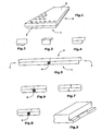
- FIG. 1 shows a schematic view of the perforated plate according to the invention, in which at least the side surfaces 3 shown are formed as strignfalze.
- the devisnfalze can be symmetrical, as in FIG. 1 is shown.
- FIGS. 2 and 3 show embodiments in which the side surfaces are executed in different step heights.
- FIG. 4 shows side surfaces where a chamfer has been made in the area of the shiplap.
- FIG. 5 shows a laying method of the perforated plates according to the invention.
- a perforated plate area with a stepped rebate abuts a perforated plate area without stepped rabbet, the plates colliding seamlessly in the region of the rear side 2 or only with a hairline.
- the resulting joint on the front side (visible side) 1 is then filled with a filling material 4.
- FIG. 6 shows a variant in which the perforated plates abut each other, which have stepped folds on both abutting areas, but collide on the rear side.
- the resulting joint is filled with filler 4.
- step rabbets are used to hook the plates into each other so that virtually no gap or hairline remains. This embodiment does not realize all the advantages exhibited by the other embodiments.
- FIG. 8 shows at the same time the advantage of the hooking together can be used with the filling of a joint with a corresponding different design of devisnfalze on the side plates.
- FIG. 9 shows an embodiment of the perforated plate according to the invention, in which the edge is chamfered in a partial region. This is on the one hand ensures that the filler adheres better in the resulting joint. On the other Side still allow the non-chamfered areas easier adjustment of the plate.
- FIG. 10 shows an embodiment of the perforated plate according to the invention, in which the stepped rabbet is discontinued in partial areas.
- the shiplap - as in the front variant - only partially missing, or it can be completely discontinued.
- the interruption of the devisnfalzes may also be angular, oblique, etc. Due to the remaining devisnfalz Schemee the inventive simplified alignment of the plates is still achieved. For one side surface, in some embodiments up to 90% of the shiplap may be discontinued. The remaining 10% is enough to facilitate alignment.
- FIG. 11 shows an embodiment based on FIG. 7 in which a sortfase remains on the visible side, which is preferably not filled. This results in evenly spaced visible lines during installation.
- FIG. 12 shows a variant in which Conversenfalze are formed in each opposite areas as stepped rabbet. As a result, a toothing is made possible when laying.
- the plates according to the invention typically have dimensions of 200 x 120 cm. However, it is also provided according to the invention that the plates are larger or smaller. In particular, for the home improvement sector recommend plates that have a smaller size, since their handling is easier when working overhead.
Abstract
Description
- Die Erfindung betrifft Lochplatten auf Basis von Gips, Verfahren zu ihrer Herstellung und Verfahren zu ihrer Verlegung.
- Lochplatten auf Basis von Gips, insbesondere Gipskartonlochplatten und Gipsfaserlochplatten werden unter anderem zur Verbesserung der. Raumakustik verwendet. Sie bestehen aus einer Gipsplatte, die eine Vielzahl von Öffnungen aufweist, die unterschiedliche Formen haben können. Auftreffende Schallwellen können durch die Löcher dringen und verhindern so die Schallreflexion. Zumeist ist auf der Rückseite der Lochplatte ein schalldämmendes Material wie beispielsweise eine Mineralwolle oder ein Faservlies angebracht, um den dämmenden Effekt zu verstärken.
- Typischerweise werden solche Lochplatten als Deckenmaterial benutzt, können aber auch als Wandverkleidung eingesetzt werden.
- Zur Herstellung von Lochplatten werden üblicherweise Gipsplatten gestanzt und anschließend die Randbereiche abgeschnitten, um einheitliche Plattenmaße zu erhalten. Abweichungen im Abstand der Löcher an Plattenübergängen oder Abweichungen im Verlauf durch eine nicht parallele Ausrichtung fallen aufgrund der meist regelmäßigen Lochmuster der Lochplatten deutlich störend auf.
- Typischerweise werden solche Lochplatten auf einem Träger z.B. einem Metallprofil oder einer Holzleiste montiert, wobei die benachbarten Randbereiche einen definierten Abstand aufweisen müssen. Hierzu wird der Abstand zwischen den Platten so bemessen, dass sich ein einheitlicher Abstand der Löcher ergibt. Die Ausrichtung erfolgt dabei mit entsprechenden Hilfsmitteln, die auf den jeweiligen Abstand der Löcher (je nach Lochungs-Schlitztyp) bezogen sind und dafür sorgen, dass im Übergangsbereich zwischen zwei Platten ebenfalls dieser Abstand eingehalten wird. Ziel dabei ist, ein "übergangfreies" Erscheinungsbild innerhalb der Gesamtfläche zu erzielen.
- Die zwischen den Platten entstehende Fuge wird üblicherweise mit einem Spachtelmaterial, beispielsweise Gips, verschlossen. Die Decke wird abschließend gemalt, um Farbunterschiede auszugleichen und um ein homogenes und einheitliches Erscheinungsbild zu erreichen.
- Nachteilig an dem Verfahren ist, dass die genaue Ausrichtung der Platten zueinander mindestens zwei, besser drei Personen erfordert, die Erfahrungen auf dem Gebiet haben müssen und die Ausrichtung trotzdem sehr zeitaufwendig ist.
- Die
EP 1 369 215 A2 offenbart ein Verfahren zur Herstellung von Gipskartonlochplatten, die eine hohe Maßhaltigkeit zeigen. Die gemäß dem dort beschriebenen Verfahren hergestellten Platten können fugenlos unmittelbar aneinander anstoßend verlegt werden, so dass nur eine Haarfuge verbleibt. - Obwohl sich hierdurch grundsätzlich eine leichtere Verlegung erreichen lässt, ist nachteilig, dass aufgrund des fehlenden Fugenbereichs geringe Unterschiede im Wand- oder Deckenverlauf bzw. Höhenunterschiede der montierten Platten nicht ausgeglichen werden können. Darüber hinaus führen schon geringe Beschädigungen an den Plattenkanten dazu, dass an der Haarfuge Bereiche vorhanden sind, in denen eine breitere, unregelmäßige Fuge entsteht, die vor dem abschließenden Streichen ausgebessert werden muss.
- Auch bei dem in der
EP 1 369 215 A2 beschriebenen Verfahren wird die Fuge im nach hinein gegebenenfalls nachbearbeitet werden müssen, beispielsweise um überstehende Reste der zum Schließen der verbleibenden Restfuge eingesetzten klebstoffähnlichen Produkte zu entfernen. -
US 2,256,761 offenbart einen Fugenverstärker beispielsweise aus Metall, in den Gipsplatten mit einer Stufenfalz eingeführt werden können. Die Metallklammer wird dann beim Verputzen der entstandenen Gipsplattenwand verdeckt. Solche Lösungen sind auf Lochplatten nicht übertragbar, da Lochplatten normalerweise nicht ganzflächig verputzt werden. -
DE 102 37 076 A1 offenbart einen Plattenverband, bei dem eine Platte durch Zwischenfugen voneinander beabstandet sind, die mit einem vorgefertigten Verschließkörper verschlossen sind. Dabei können die Platten zur Aufnahme der von Teilen der Verschließkörper Stufenfalze aufweisen. -
DE 203 05 9714 U1 zeigt eine Stirnkantenverbindung für das Verlegen von Gipskartonplatten und Gipskarton-Akustik-Lochplatten, bei denen stirnseitig ein Wellenprofil eingefräst sind. - Die vorliegende Erfindung hat sich die Aufgabe gestellt, die oben genannten Nachteile des Standes der Technik zu überwinden.
- Gelöst wird die Aufgabe durch eine Lochplatte auf Basis von Gips mit einer Vorder- und einer Hinterseite und vier Seitenflächen, wobei mindestens zwei benachbarte Seitenflächen als Stufenfalz ausgebildet sind, wobei der Stufenfalz so ausgebildet ist, dass beim Verlegen der Lochplatte mit einer als Stufenfalz ausgebüdeten Seite in Kontakt mit einer zweiten Lochplatte einheitliche Lochabstände ausgebildet sind.
- Benachbart bedeutet, dass zwei Seitenflächen an einer Ecke der Platte aufeinandertreffen.
- Fuge bedeutet eine auszufüllende Öffnung von mindestens 2 mm Breite. Ausführungsformen, bei denen zwei Platenkanten direkt aneinander stoßen und möglichst keine Fuge entstehen soll, werden im weiteren als Haar-Fugen bezeichnet.
- Stufenfalz bedeutet, dass der Seitenbereich in Form einer Stufe ausgebildet ist. Dabei kann die Stufe unterschiedliche Höhen bzw. Breiten aufweisen. Darüber hinaus müssen die Kanten nicht rechtwinklig sein, auch abgefast oder gerundete Gestaltungen sind möglich. Abgerundete oder gefaste Kanten können sowohl in Bereichen mit Stufenfalz als auch in einem Bereich ohne Stufenfalz sein. Es ist auch möglich, dass zur Sichtseite eine "Sichtfuge" verbleibt, die nicht verspachtelt wird. Bei einer Sichtfuge ist ein Teil der Fuge geschlossen, während auf der Sichtseite eine Fuge verbleibt.
- Es ist auch möglich, dass die Abfasung nicht über die gesamte Länge einer Kante besteht. Es können auch Bereiche existieren, in denen der Stufenfalz ganz oder teilweise abgesetzt ist, dass heißt, dass der Stufenfalz nur in Teilbereichen der Seitenflächen vorhanden ist, und in den anderen Bereichen ganz oder teilweise fehlt.
- In einer Ausführungsform der Erfindung weist die erfindungsgemäße Lochplatte genau zwei benachbarte Seitenflächen in Form einer Stufenfalz auf. Bei der Montage solcher Platten wird jeweils die Montage so durchgeführt, dass eine Lochplatte mit einer Seitenfläche mit Stufenfalz auf eine nicht als Stufenfalz ausgebildete Seitenfläche trifft, so dass eine in den Raum hinein zeigende Fuge verbleibt. Da die Lochplatten bei dieser Montageweise direkt aneinander stoßen, ist die Montage gegenüber dem Standardverfahren wesentlich erleichtert, da klein Justieren bzw. nur geringfügiges Nachrichten in Abhängigkeit der Lochmuster erforderlich ist. Auch ein Verkanten, bei dem die Lochplatten nicht mehr parallel zueinander ausgerichtet sind, ist weitestgehend ausgeschlossen. Die so entstandene Fuge kann in üblicher Weise mit einem Füll- bzw. Spachtelmaterial, beispielsweise einem Baukleber, Acrylmaterial, Dispersions- oder mineralisch gebundene Materialien oder Mischungen daraus oder - besonders bevorzugt - einem gipsgebundenen Material gefüllt werden.
- Hierbel zeigen sich weitere Vorteile der Erfindung. Beim klassischen Montageverfahren ist die Fuge zur Hinterseite, d.h. zur Wand oder Decke im allgemeinen offen, da die Lochplatten auf ein Holz- oder Metallprofilgerüst montiert werden. Eingebrachtes Füllmaterial kann daher praktisch unbegrenzt auf der Rückseite der Fuge austreten, so dass ein Verfüllen der Fuge nicht unter Druck erfolgen kann. Ein zumindest geringer Druck ist jedoch für eine gute Anhaftung des Füllmaterials an den Seitenflächen der Lochplatte hilfreich.
- Dadurch, dass nun erfindungsgemäß die Platten an der Hinterseite aneinander stoßen bzw. nur einen Spalt von geringer Breite aufweisen, kann das Füllmaterial dort nicht mehr aus der Fuge austreten, so dass die Verfugung leichter und haltbarer vorgenommen werden kann. Dadurch wird eine wesentlich bessere Flankenhaftung der Füll- bzw. Spachtel- und Klebematerialien erzielt.
- Auf der andere Seite können, da weiterhin eine Verfugung vorgenommen wird, kleinere Schäden an den Kanten (sowohl auf Vorder- oder Rückseite) oder Höhenunterschiede zwischen den montierten Platten im Rahmen der Verfugung ausgeglichen werden.
- In einer anderen Ausführungsform der Erfindung weist die Lochplatte an allen vier Seitenflächen Stufenfalze auf. In dieser Ausführungsform lassen sich drei Varianten der Verlegung verwirklichen.
- Zum einen können die Stufenfalze beide auf der Hinterseite angebracht sein und dann auf Stoß verlegt werden. Eine so entstehende Fuge wird dann wiederum mit einem Füllmaterial gefüllt oder kann auch offen bleiben. Hierbei muss darauf geachtet werden, dass die entstehende Fugenbreite und damit die Größe des Stufenfalzes so gewählt wird, dass die fertige Wand oder Decke noch einheitliche Lochabstände aufweist bzw. ein einheitliches sichtbar bleibendes Fugenbild entsteht.
- Auch in einem solchen Fall ist die Verlegung erheblich vereinfacht, da das Ausrichten der Platte wesentlich leichter erfolgt.
- Zum zweiten können die Platten auch so eingesetzt werden, dass die Stufenfalze mal auf der Vorder- und mal auf der Hinterseite sind und somit ineinander greifen. In diesem Fall kann eine praktisch fugenlose Verlegung erreicht werden, wobei in vorteilhafter Weise die neu zu verlegende Platte in die schon montierte Platte mit Hilfe des Stufenfalzes eingehakt wird, so dass das Gewicht der Platte zum Teil von der schon montierten Platte getragen wird.
- Dabei können die Platten so ausgebildet sein, dass gegenüberliegende Seiten den längeren Bereich des Stufenfalzes mal auf der Ober- und mal auf der Unterseite haben. Alternativ können die längeren Bereiche der Stufenfalze auch jeweils auf der gleichen Seite liegen, wobei die zweite Platte dann im Einsatz gedreht wird, um ein Ineinandergreifen der Platten zu ermöglichen.
- Diese Verlegung kann sowohl "trocken" (d.h. ohne Kleber oder ähnliches) als auch wie beschrieben mit Verklebung bzw. Verspachtelung erfolgen.
- In der dritten Variante sind die Stufenfalze an den verschiedenen Seitenflächen unterschiedlich ausgebildet, so dass zum einen ein Einhängen in die schon montierte Platte möglich ist, auf der anderen Seite aber auch dann noch eine Fuge verbleibt, die hinterher mit einem Füllmaterial verschlossen wird.
- Alle Ausführungsformen der Erfindung, die das Verschließen einer Fuge mit einem Füllmaterial beinhalten, haben den Vorteil, dass zum einen geringe Höhenunterschiede zwischen den montierten Platten ausgeglichen werden können und Schäden an den Kanten durch das Füll- bzw. Spachtelmaterial, beispielsweise einen Baukleber, ein Acrylmaterial, Dispersions- oder mineralisch gebundene Materialien oder Mischungen daraus oder besonders bevorzugt ein gipsgebundenes Material in einem Arbeitsgang mit repariert werden bzw. mögliche Lochversatze durch geringfügiges Nacharbeiten der Plattenstufung ausgeglichen werden.
- Die erfindungsgemäßen Lochplatten können in einfacher Weise erhalten werden, in dem eine Platte in einem Arbeitsgang gestanzt und anschließend geschnitten wird. Die Stufenfalze können auf verschiedene Weise erhalten werden. In einer Ausführungsform erfolgt dies durch zweimaliges Schneiden, d.h. zunächst wird die gesamte Platte geschnitten und anschließend wird mit verminderter Tiefe erneut geschnitten, um einen Stufenfalz zu erhalten. Es kann auch in einem Durchgang ein Vorritzen, Sägen und Falzen erfolgen. Alternativ dazu kann nach dem ersten Schneiden auch eine Fräse eingesetzt werden, um einen Stufenfalz auszubilden. In einer besonders bevorzugten Ausführungsform wird ein Stufenwerkzeug verwendet, mit dem gleichzeitig in zwei verschiedene Höhen geschnitten werden kann. Ein solches Werkzeug lässt sich durch unterschiedliche Tiefe der Führung sowohl zum Schneiden von Stufenfalzen als auch zum Schneiden von geraden Seitenflächen einsetzen.
- Gegenstand der Erfindung ist auch eine Anordnung ("Verbund") der erfindungsgemäßen Platten.
- Die Erfindung wird durch den nachfolgenden Zeichnungen weiter erläutert.
-
Figur 1 zeigt eine schematische Ansicht der erfindungsgemäßen Lochplatte, bei der zumindest die gezeigten Seitenflächen 3 als Stufenfalze ausgebildet sind. Die Stufenfalze können symmetrisch sein, wie dies inFigur 1 dargestellt ist. - Die
Figuren 2 und 3 zeigen Ausführungsformen, bei denen die Seitenflächen in unterschiedlichen Stufenhöhen ausgeführt sind. -
Figur 4 zeigt Seitenflächen, bei denen im Bereich des Stufenfalz eine Abfasung vorgenommen wurde. -
Figur 5 zeigt eine Verlegungsart der erfindungsgemäßen Lochplatten. Hierbei stößt ein Lochplattenbereich mit einem Stufenfalz an einen Lochplattenbereich ohne Stufenfalz, wobei die Platten im Bereich der Hinterseite 2 fugenlos bzw. nur mit einer Haarfuge zusammenstoßen. Die entstehende Fuge auf der Vorderseite (Sichtseite) 1 wird dann mit einem Füllmaterial 4 verfüllt. -
Figur 6 zeigt eine Variante, bei der Lochplatten aneinander stoßen, die an beiden zusammenstoßenden Bereichen Stufenfalze aufweisen, aber auf der Hinterseite zusammenstoßen. Die entstehende Fuge wird mit Füllmaterial 4 verfüllt. - In einer weiteren Ausführungsform gemäß
Figur 7 werden die Stufenfalze verwendet, um die Platten ineinander zu haken, so dass praktisch keine Fuge bzw. eine Haarfuge verbleibt. Diese Ausführungsform verwirklicht nicht alle Vorteile, die die anderen Ausführungsformen zeigen. - In einer weiteren Ausführungsform zeigt
Figur 8 wie gleichzeitig der Vorteil des Ineinanderhakens mit dem Verfüllen einer Fuge bei entsprechender unterschiedlicher Gestaltung der Stufenfalze an den Seitenplatten genutzt werden kann. -
Figur 9 zeigt eine Ausführungsform der erfindungsgemäßen Lochplatte, bei der die Kante in einem Teilbereich abgefast ist. Hiermit wird zum einen erreicht, dass das Füllmaterial besser in der entstehenden Fuge haftet. Auf der anderen Seite erlauben die weiterhin vorhandenen, nicht abgefasten Bereiche ein leichteres Justieren der Platte. -
Figur 10 zeigt eine Ausführungsform der erfindungsgemäßen Lochplatte, bei der der Stufenfalz in Teilbereichen abgesetzt ist. Dabei kann der Stufenfalz - wie in der vorderen Variante - nur teilweise fehlen, oder er kann komplett abgesetzt sein. Die Unterbrechung des Stufenfalzes kann auch eckig, schräg etc. sein. Durch die verbleibenden Stufenfalzbereiche wird die erfindungsgemäße vereinfachte Ausrichtung der Platten weiterhin erreicht. Für eine Seitenfläche kann bei einigen Ausführungsformen bis zu 90% des Stufenfalzes abgesetzt sein. Die verbleibenden 10% genügen zur Erleichterung der Ausrichtung. -
Figur 11 zeigt eine Ausführungsform in Anlehnung anFigur 7 , bei der an der Sichtseite eine Sichtfase verbleibt, die bevorzugt nicht verspachtelt wird. Es entstehen so im gleichmäßigen Abstand sichtbare Linien bei der Verlegung. -
Figur 12 zeigt eine Variante, bei der Stufenfalze in jeweils gegenüberliegenden Bereichen als Stufenfalz ausgebildet sind. Hierdurch wird bei der Verlegung eine Verzahnung ermöglicht. - Die erfindungsgemäßen Platten haben typischerweise Maße von 200 x 120 cm. Es ist erfindungsgemäß jedoch auch vorgesehen, dass die Platten größer oder kleiner sind. Insbesondere für den Heimwerkerbereich empfehlen sich Platten, die eine geringere Größe haben, da deren Handhabung beim Arbeiten über Kopf erleichtert ist.
Claims (14)
- Lochplatte auf Basis von Gips mit einer Vorder- (1) und einer Hinterseite remove underlining benachbarte (2) und vier Seitenflächen (3), wobei mindestens zwei benachbarte Seitenflächen (3) als Stufenfalz ausgebildet sind, wobei der Stufenfalz so ausgebildet ist, dass beim Verlegen der Lochelatte mit einer als Stufenfalz ausgebildeten Seite in Kontakt mit einer zweiten Lochplatte, eine gebildete fertige Wand oder Decke einheitliche Lochabstände aufweist.
- Lochplatte auf Basis von Gips nach Anspruch 1, dadurch gekennzeichnet, dass es sich um eine Gipskartonlochplatte oder eine Gipsfaserlochplatte handelt.
- Lochplatte auf Basis von Gips nach mindestens einem der Ansprüche 1 oder 2 dadurch gekennzeichnet, dass mindestens eine Seitenfläche an mindestens einer Kante gefast ist.
- Lochplatte auf Basis von Gips nach Anspruch 3 dadurch gekennzeichnet, dass mindestens eine als Stufenfalz ausgebildete Seitenfläche gefast ist.
- Lochplatte auf Basis von Gips nach mindestens einem der Ansprüche 1 bis 4, dadurch gekennzeichnet, dass genau zwei Seitenflächen als Stufenfalz ausgebildet sind.
- Lochplatte auf Basis von Gips nach mindestens einem der Ansprüche 1 bis 5, dadurch gekennzeichnet, dass vier Seitenflächen als Stufenfalz ausgebildet sind.
- Lochplatte nach mindestens einem der Ansprüche 1 bis 6, dadurch gekennzeichnet, dass der Stufenfalz ganz oder teilweise abgesetzt ist.
- Anordnung mit mindestens zwei Lochplatten auf Basis von Gips nach mindestens einem der Ansprüche 1 bis 7, wobei eine erste Lochplatte auf Basis von Gips mit einer als Stufenfalz ausgebildeten Seite in Kontakt mit einer zweiten Lochplatte auf Basis von Gips steht und eine dazwischen befindli-che Fuge mit einem Füllmaterial verschlossen ist.
- Anordnung mit mindestens zwei Lochplatten auf Basis von Gips nach mindestens einem der Ansprüche 1 bis 7, wobei eine erste Lochplatte auf Basis von Gips mit einer als Stufenfalz ausgebildeten Seite in Kontakt mit einer Lochplatte auf Basis von Gips mit einer ebenfalls als Stufenfalz ausgebildeten Seite steht, so dass keine Fuge, eine Haarfuge oder eine Sichtfuge verbleibt.
- Anordnung nach Anspruch 8, dadurch gekennzeichnet, dass das Füllmaterial ein Füll- bzw. Spachtelmaterial, beispielsweise einem Baukleber, Acrylmaterial, Dispersions- oder mineralisch gebundene Materialien oder aber Mischungen daraus oder besonders bevorzugt einem gipsgebundenen Material ist.
- Verfahren zur Herstellung einer Lochplatte auf Basis von Gips nach mindestens einem der Ansprüche 1 bis 7 mit folgenden Schritten:• Stanzen einer Gipsplatte, um eine Lochplatte auf Basis von Gips zu erhalten,• Schneiden entlang der Seitenflächen, wobei mindestens zwei benachbarte Seitenflächen als Stufenfalz ausgebildet werden.
- Verfahren zum Verlegen von Lochplatten auf Basis von Gips nach mindestens einem der Ansprüche 1 bis 7, wobei eine Lochplatte auf Basis von Gips mit einer als Stufenfalz ausgebildeten Seite in Kontakt mit einer Lochplatte auf Basis von Gips gebracht, so dass eine Fuge entsteht, die mit einem Füllmaterial verschlossen wird.
- Verfahren zum Verlegen von Lochplatten auf Basis von Gips nach mindestens einem der Ansprüche 1 bis 7, wobei eine Lochplatte auf Basis von Gips mit einer als Stufenfalz ausgebildeten Seite in Kontakt mit einer Lochplatte auf Basis von Gips mit einer ebenfalls als Stufenfalz ausgebildeten Seite gebracht wird, so dass keine Fuge entsteht.
- Verfahren zum Verlegen von Lochplatten auf Basis von Gips nach mindestens einem der Ansprüche 4 bis 7, wobei eine Lochplatte auf Basis von Gips mit einer als Stufenfalz ausgebildeten Seite in Kontakt mit einer Lochplatte auf Basis von Gips mit einer ebenfalls als Stufenfalz ausgebildeten Seite gebracht wird, und wobei mindestens ein Stufenfalz so gefast ist, dass eine Sichtfuge verbleibt.
Priority Applications (3)
| Application Number | Priority Date | Filing Date | Title |
|---|---|---|---|
| DE202005021353U DE202005021353U1 (de) | 2004-12-22 | 2005-12-22 | Lochplatte auf Basis von Gips |
| PL05850485T PL1831476T3 (pl) | 2004-12-22 | 2005-12-22 | Płyta perforowana na bazie gipsu |
| EP05850485.3A EP1831476B9 (de) | 2004-12-22 | 2005-12-22 | Lochplatte auf basis von gips |
Applications Claiming Priority (3)
| Application Number | Priority Date | Filing Date | Title |
|---|---|---|---|
| EP04106897A EP1674630A1 (de) | 2004-12-22 | 2004-12-22 | Lochplatte auf Basis von Gips |
| PCT/EP2005/057095 WO2006067213A1 (de) | 2004-12-22 | 2005-12-22 | Lochplatte auf basis von gips |
| EP05850485.3A EP1831476B9 (de) | 2004-12-22 | 2005-12-22 | Lochplatte auf basis von gips |
Publications (3)
| Publication Number | Publication Date |
|---|---|
| EP1831476A1 EP1831476A1 (de) | 2007-09-12 |
| EP1831476B1 true EP1831476B1 (de) | 2012-08-15 |
| EP1831476B9 EP1831476B9 (de) | 2014-09-03 |
Family
ID=38331206
Family Applications (1)
| Application Number | Title | Priority Date | Filing Date |
|---|---|---|---|
| EP05850485.3A Revoked EP1831476B9 (de) | 2004-12-22 | 2005-12-22 | Lochplatte auf basis von gips |
Country Status (3)
| Country | Link |
|---|---|
| EP (1) | EP1831476B9 (de) |
| DE (1) | DE202005021353U1 (de) |
| PL (1) | PL1831476T3 (de) |
Families Citing this family (2)
| Publication number | Priority date | Publication date | Assignee | Title |
|---|---|---|---|---|
| PT2971391T (pt) * | 2013-03-15 | 2018-10-19 | Usg Interiors Llc | Tecto monolítico de painéis de gesso acústicos |
| CH711582A1 (de) * | 2015-09-29 | 2017-03-31 | Akustik & Raum Ag | Schallabsorbierendes Element. |
Family Cites Families (7)
| Publication number | Priority date | Publication date | Assignee | Title |
|---|---|---|---|---|
| DE278536C (de) | ||||
| DE1847585U (de) | 1961-12-05 | 1962-03-01 | Schallex G M B H & Co | Schallschluck- oder abdeckplatte. |
| DE1854591U (de) | 1962-05-16 | 1962-07-05 | Wilhelm Hoch | Schallschluckplatte. |
| DE6917171U (de) | 1969-04-24 | 1969-10-23 | Franz Drepper Kg Fa | Verkleidungsplatte fuer wand-und/oder deckenbekleidung |
| DE2203955A1 (de) | 1971-02-01 | 1972-08-17 | Gullfiber Ab, Billesholm (Schweden) | Deckenverkleidung |
| DE10054978B4 (de) | 2000-08-26 | 2006-03-16 | Karl Bauer | Gipskarton-Platte mit einer randseitingen, sich über die ganze Länge eines Seitenrandes erstreckende Ausnehmung, Verfahren zur Herstellung und Verwendung derselben |
| DE10237076A1 (de) | 2002-08-09 | 2004-02-19 | Inbau Bausysteme Gmbh & Co. Kg | Plattenverband aus Platten aus einem Gipswerkstoff und Verfahren zum Herstellen eines Plattenverbandes |
-
2005
- 2005-12-22 PL PL05850485T patent/PL1831476T3/pl unknown
- 2005-12-22 EP EP05850485.3A patent/EP1831476B9/de not_active Revoked
- 2005-12-22 DE DE202005021353U patent/DE202005021353U1/de not_active Expired - Lifetime
Also Published As
| Publication number | Publication date |
|---|---|
| DE202005021353U1 (de) | 2007-09-27 |
| EP1831476A1 (de) | 2007-09-12 |
| EP1831476B9 (de) | 2014-09-03 |
| PL1831476T3 (pl) | 2013-01-31 |
Similar Documents
| Publication | Publication Date | Title |
|---|---|---|
| EP0017050B1 (de) | Wärmegedämmte Fassade | |
| DE2233301A1 (de) | Bauplatte und verfahren zu ihrer herstellung | |
| EP1038073B1 (de) | Raumbegrenzung aus fertigelementen, wie aussenwände, trennwände und geschossdecken oder dergleichen und verfahren zu deren aufbau | |
| WO2006067213A1 (de) | Lochplatte auf basis von gips | |
| EP1689954B1 (de) | Verfahren zur herstellung von abgehängten decken aus gipskar ton-platten | |
| DE19951105C2 (de) | Wärme- und/oder Schalldämmelement | |
| EP3307964A1 (de) | Verbindungselement für wandbauelemente | |
| EP1831476B1 (de) | Lochplatte auf basis von gips | |
| EP0641905B1 (de) | Zementgebundenes Schalbrett mit Sollknickstelle | |
| DE4143387A1 (de) | Verfahren zum herstellen von formkoerpern, insbesondere von daemmplatten | |
| EP2067905B1 (de) | Vorgefertigtes Verkleidungselement für ein Außenmauerwerk im Bereich einer Fenster- oder Türlaibung | |
| EP4087984B1 (de) | System und verfahren zum errichten von gebäudewänden, -decken und/oder -dächern | |
| DE10054978B4 (de) | Gipskarton-Platte mit einer randseitingen, sich über die ganze Länge eines Seitenrandes erstreckende Ausnehmung, Verfahren zur Herstellung und Verwendung derselben | |
| EP0006098B1 (de) | Verfahren zur Herstellung von Gipskartonplatten mit mindestens einer abgeschrägten Stirnseite | |
| EP3015614B1 (de) | Wandplatte für den trockenbau aus einem holzwerkstoff sowie wandaufbau und verfahren zum herstellen des wandaufbaus mit der wandplatte | |
| DE102006024792B3 (de) | Verfahren zur Schaffung einer Wärmedämmung für Fassaden im Bereich eines Fensters | |
| DE102020112180A1 (de) | Verfahren zur Ausbildung einer Innenecke zwischen wenigstens zwei winklig aneinander angrenzenden Bauplatten eines Wandaufbaus, insbesondere eines Wandaufbaus eines in Holzrahmenbauweise oder Holztafelbauweise gefertigten Fertighauses | |
| DE3212245C2 (de) | Verfahren zur Herstellung eines wärmeisolierenden Bauelementes | |
| DE19637379A1 (de) | Verfahren und Vorrichtung zum Herstellen von Bauelementen sowie danach hergestellte Bauelemente | |
| EP0940518A1 (de) | Verkleidungselement zum Verkleiden von Gebäudewänden | |
| EP1918469B1 (de) | Wärmedämmverbundsystem | |
| DE19607895C2 (de) | Schalldämmplatte sowie schalldämmende Verkleidung mit einer Schalldämmplatte | |
| DE3426653A1 (de) | Dachgaube | |
| DE3305475C2 (de) | Akustikdeckenplatte aus einem Fasermaterial | |
| EP0044467A1 (de) | Profiliertes Bauelement und daraus errichtetes Raumbegrenzungs- und/oder Raumunterteilungs-Baukonstruktionsteil, sowie Verfahren zur Erzeugung solcher profilierter Bauelemente |
Legal Events
| Date | Code | Title | Description |
|---|---|---|---|
| PUAI | Public reference made under article 153(3) epc to a published international application that has entered the european phase |
Free format text: ORIGINAL CODE: 0009012 |
|
| 17P | Request for examination filed |
Effective date: 20070613 |
|
| AK | Designated contracting states |
Kind code of ref document: A1 Designated state(s): AT BE BG CH CY CZ DE DK EE ES FI FR GB GR HU IE IS IT LI LT LU LV MC NL PL PT RO SE SI SK TR |
|
| DAX | Request for extension of the european patent (deleted) | ||
| GRAP | Despatch of communication of intention to grant a patent |
Free format text: ORIGINAL CODE: EPIDOSNIGR1 |
|
| TPAC | Observations by third parties |
Free format text: ORIGINAL CODE: EPIDOSNTIPA |
|
| GRAS | Grant fee paid |
Free format text: ORIGINAL CODE: EPIDOSNIGR3 |
|
| GRAJ | Information related to disapproval of communication of intention to grant by the applicant or resumption of examination proceedings by the epo deleted |
Free format text: ORIGINAL CODE: EPIDOSDIGR1 |
|
| 17Q | First examination report despatched |
Effective date: 20080804 |
|
| TPAC | Observations by third parties |
Free format text: ORIGINAL CODE: EPIDOSNTIPA |
|
| REG | Reference to a national code |
Ref country code: DE Ref legal event code: R079 Ref document number: 502005013021 Country of ref document: DE Free format text: PREVIOUS MAIN CLASS: E04B0001860000 Ipc: E04B0009000000 |
|
| GRAP | Despatch of communication of intention to grant a patent |
Free format text: ORIGINAL CODE: EPIDOSNIGR1 |
|
| RIC1 | Information provided on ipc code assigned before grant |
Ipc: E04C 2/04 20060101ALI20111117BHEP Ipc: E04B 9/00 20060101AFI20111117BHEP Ipc: E04F 13/08 20060101ALI20111117BHEP |
|
| GRAS | Grant fee paid |
Free format text: ORIGINAL CODE: EPIDOSNIGR3 |
|
| GRAA | (expected) grant |
Free format text: ORIGINAL CODE: 0009210 |
|
| STAA | Information on the status of an ep patent application or granted ep patent |
Free format text: STATUS: THE PATENT HAS BEEN GRANTED |
|
| AK | Designated contracting states |
Kind code of ref document: B1 Designated state(s): AT BE BG CH CY CZ DE DK EE ES FI FR GB GR HU IE IS IT LI LT LU LV MC NL PL PT RO SE SI SK TR |
|
| REG | Reference to a national code |
Ref country code: GB Ref legal event code: FG4D Free format text: NOT ENGLISH Ref country code: CH Ref legal event code: EP Ref country code: AT Ref legal event code: REF Ref document number: 570938 Country of ref document: AT Kind code of ref document: T Effective date: 20120815 |
|
| REG | Reference to a national code |
Ref country code: IE Ref legal event code: FG4D Free format text: LANGUAGE OF EP DOCUMENT: GERMAN |
|
| REG | Reference to a national code |
Ref country code: PT Ref legal event code: SC4A Free format text: AVAILABILITY OF NATIONAL TRANSLATION Effective date: 20120919 |
|
| REG | Reference to a national code |
Ref country code: DE Ref legal event code: R096 Ref document number: 502005013021 Country of ref document: DE Effective date: 20121011 |
|
| REG | Reference to a national code |
Ref country code: GR Ref legal event code: EP Ref document number: 20120402101 Country of ref document: GR Effective date: 20120915 |
|
| REG | Reference to a national code |
Ref country code: CH Ref legal event code: NV Representative=s name: SCHMAUDER & PARTNER AG PATENT- UND MARKENANWAELTE |
|
| REG | Reference to a national code |
Ref country code: NL Ref legal event code: T3 Ref country code: ES Ref legal event code: FG2A Ref document number: 2391643 Country of ref document: ES Kind code of ref document: T3 Effective date: 20121128 |
|
| REG | Reference to a national code |
Ref country code: DK Ref legal event code: T3 |
|
| PG25 | Lapsed in a contracting state [announced via postgrant information from national office to epo] |
Ref country code: LT Free format text: LAPSE BECAUSE OF FAILURE TO SUBMIT A TRANSLATION OF THE DESCRIPTION OR TO PAY THE FEE WITHIN THE PRESCRIBED TIME-LIMIT Effective date: 20120815 Ref country code: CY Free format text: LAPSE BECAUSE OF FAILURE TO SUBMIT A TRANSLATION OF THE DESCRIPTION OR TO PAY THE FEE WITHIN THE PRESCRIBED TIME-LIMIT Effective date: 20120815 Ref country code: FI Free format text: LAPSE BECAUSE OF FAILURE TO SUBMIT A TRANSLATION OF THE DESCRIPTION OR TO PAY THE FEE WITHIN THE PRESCRIBED TIME-LIMIT Effective date: 20120815 Ref country code: IS Free format text: LAPSE BECAUSE OF FAILURE TO SUBMIT A TRANSLATION OF THE DESCRIPTION OR TO PAY THE FEE WITHIN THE PRESCRIBED TIME-LIMIT Effective date: 20121215 |
|
| PGFP | Annual fee paid to national office [announced via postgrant information from national office to epo] |
Ref country code: IE Payment date: 20121213 Year of fee payment: 8 Ref country code: DK Payment date: 20121219 Year of fee payment: 8 Ref country code: CH Payment date: 20121218 Year of fee payment: 8 |
|
| REG | Reference to a national code |
Ref country code: PL Ref legal event code: T3 |
|
| PG25 | Lapsed in a contracting state [announced via postgrant information from national office to epo] |
Ref country code: SE Free format text: LAPSE BECAUSE OF FAILURE TO SUBMIT A TRANSLATION OF THE DESCRIPTION OR TO PAY THE FEE WITHIN THE PRESCRIBED TIME-LIMIT Effective date: 20120815 Ref country code: SI Free format text: LAPSE BECAUSE OF FAILURE TO SUBMIT A TRANSLATION OF THE DESCRIPTION OR TO PAY THE FEE WITHIN THE PRESCRIBED TIME-LIMIT Effective date: 20120815 Ref country code: LV Free format text: LAPSE BECAUSE OF FAILURE TO SUBMIT A TRANSLATION OF THE DESCRIPTION OR TO PAY THE FEE WITHIN THE PRESCRIBED TIME-LIMIT Effective date: 20120815 |
|
| PGFP | Annual fee paid to national office [announced via postgrant information from national office to epo] |
Ref country code: GR Payment date: 20121221 Year of fee payment: 8 Ref country code: PT Payment date: 20121217 Year of fee payment: 8 |
|
| PGFP | Annual fee paid to national office [announced via postgrant information from national office to epo] |
Ref country code: NL Payment date: 20121217 Year of fee payment: 8 Ref country code: AT Payment date: 20121214 Year of fee payment: 8 |
|
| PG25 | Lapsed in a contracting state [announced via postgrant information from national office to epo] |
Ref country code: RO Free format text: LAPSE BECAUSE OF FAILURE TO SUBMIT A TRANSLATION OF THE DESCRIPTION OR TO PAY THE FEE WITHIN THE PRESCRIBED TIME-LIMIT Effective date: 20120815 Ref country code: CZ Free format text: LAPSE BECAUSE OF FAILURE TO SUBMIT A TRANSLATION OF THE DESCRIPTION OR TO PAY THE FEE WITHIN THE PRESCRIBED TIME-LIMIT Effective date: 20120815 Ref country code: EE Free format text: LAPSE BECAUSE OF FAILURE TO SUBMIT A TRANSLATION OF THE DESCRIPTION OR TO PAY THE FEE WITHIN THE PRESCRIBED TIME-LIMIT Effective date: 20120815 |
|
| PGFP | Annual fee paid to national office [announced via postgrant information from national office to epo] |
Ref country code: BE Payment date: 20121217 Year of fee payment: 8 |
|
| PG25 | Lapsed in a contracting state [announced via postgrant information from national office to epo] |
Ref country code: SK Free format text: LAPSE BECAUSE OF FAILURE TO SUBMIT A TRANSLATION OF THE DESCRIPTION OR TO PAY THE FEE WITHIN THE PRESCRIBED TIME-LIMIT Effective date: 20120815 |
|
| PLBI | Opposition filed |
Free format text: ORIGINAL CODE: 0009260 |
|
| PLAX | Notice of opposition and request to file observation + time limit sent |
Free format text: ORIGINAL CODE: EPIDOSNOBS2 |
|
| 26 | Opposition filed |
Opponent name: SAINT-GOBAIN PLACO SAS Effective date: 20130515 |
|
| PG25 | Lapsed in a contracting state [announced via postgrant information from national office to epo] |
Ref country code: MC Free format text: LAPSE BECAUSE OF NON-PAYMENT OF DUE FEES Effective date: 20121231 Ref country code: BG Free format text: LAPSE BECAUSE OF FAILURE TO SUBMIT A TRANSLATION OF THE DESCRIPTION OR TO PAY THE FEE WITHIN THE PRESCRIBED TIME-LIMIT Effective date: 20121115 |
|
| REG | Reference to a national code |
Ref country code: DE Ref legal event code: R026 Ref document number: 502005013021 Country of ref document: DE Effective date: 20130515 |
|
| PLAF | Information modified related to communication of a notice of opposition and request to file observations + time limit |
Free format text: ORIGINAL CODE: EPIDOSCOBS2 |
|
| PLAF | Information modified related to communication of a notice of opposition and request to file observations + time limit |
Free format text: ORIGINAL CODE: EPIDOSCOBS2 |
|
| PLBB | Reply of patent proprietor to notice(s) of opposition received |
Free format text: ORIGINAL CODE: EPIDOSNOBS3 |
|
| PG25 | Lapsed in a contracting state [announced via postgrant information from national office to epo] |
Ref country code: TR Free format text: LAPSE BECAUSE OF FAILURE TO SUBMIT A TRANSLATION OF THE DESCRIPTION OR TO PAY THE FEE WITHIN THE PRESCRIBED TIME-LIMIT Effective date: 20120815 |
|
| PG25 | Lapsed in a contracting state [announced via postgrant information from national office to epo] |
Ref country code: LU Free format text: LAPSE BECAUSE OF NON-PAYMENT OF DUE FEES Effective date: 20121222 |
|
| BERE | Be: lapsed |
Owner name: KNAUF GIPS K.G. Effective date: 20131231 |
|
| REG | Reference to a national code |
Ref country code: PT Ref legal event code: MM4A Free format text: LAPSE DUE TO NON-PAYMENT OF FEES Effective date: 20140623 |
|
| REG | Reference to a national code |
Ref country code: DK Ref legal event code: EBP Effective date: 20131231 |
|
| REG | Reference to a national code |
Ref country code: NL Ref legal event code: V1 Effective date: 20140701 |
|
| PG25 | Lapsed in a contracting state [announced via postgrant information from national office to epo] |
Ref country code: HU Free format text: LAPSE BECAUSE OF FAILURE TO SUBMIT A TRANSLATION OF THE DESCRIPTION OR TO PAY THE FEE WITHIN THE PRESCRIBED TIME-LIMIT Effective date: 20051222 |
|
| REG | Reference to a national code |
Ref country code: CH Ref legal event code: PL |
|
| REG | Reference to a national code |
Ref country code: AT Ref legal event code: MM01 Ref document number: 570938 Country of ref document: AT Kind code of ref document: T Effective date: 20131222 |
|
| PG25 | Lapsed in a contracting state [announced via postgrant information from national office to epo] |
Ref country code: PT Free format text: LAPSE BECAUSE OF NON-PAYMENT OF DUE FEES Effective date: 20140623 |
|
| REG | Reference to a national code |
Ref country code: GR Ref legal event code: ML Ref document number: 20120402101 Country of ref document: GR Effective date: 20140702 |
|
| REG | Reference to a national code |
Ref country code: IE Ref legal event code: MM4A |
|
| PG25 | Lapsed in a contracting state [announced via postgrant information from national office to epo] |
Ref country code: GR Free format text: LAPSE BECAUSE OF NON-PAYMENT OF DUE FEES Effective date: 20140702 Ref country code: IE Free format text: LAPSE BECAUSE OF NON-PAYMENT OF DUE FEES Effective date: 20131222 Ref country code: NL Free format text: LAPSE BECAUSE OF NON-PAYMENT OF DUE FEES Effective date: 20140701 Ref country code: CH Free format text: LAPSE BECAUSE OF NON-PAYMENT OF DUE FEES Effective date: 20131231 Ref country code: LI Free format text: LAPSE BECAUSE OF NON-PAYMENT OF DUE FEES Effective date: 20131231 Ref country code: BE Free format text: LAPSE BECAUSE OF NON-PAYMENT OF DUE FEES Effective date: 20131231 |
|
| PG25 | Lapsed in a contracting state [announced via postgrant information from national office to epo] |
Ref country code: AT Free format text: LAPSE BECAUSE OF NON-PAYMENT OF DUE FEES Effective date: 20131222 |
|
| PG25 | Lapsed in a contracting state [announced via postgrant information from national office to epo] |
Ref country code: DK Free format text: LAPSE BECAUSE OF NON-PAYMENT OF DUE FEES Effective date: 20131231 |
|
| PLCK | Communication despatched that opposition was rejected |
Free format text: ORIGINAL CODE: EPIDOSNREJ1 |
|
| PGFP | Annual fee paid to national office [announced via postgrant information from national office to epo] |
Ref country code: PL Payment date: 20150113 Year of fee payment: 10 |
|
| APAH | Appeal reference modified |
Free format text: ORIGINAL CODE: EPIDOSCREFNO |
|
| APBM | Appeal reference recorded |
Free format text: ORIGINAL CODE: EPIDOSNREFNO |
|
| APBP | Date of receipt of notice of appeal recorded |
Free format text: ORIGINAL CODE: EPIDOSNNOA2O |
|
| APBQ | Date of receipt of statement of grounds of appeal recorded |
Free format text: ORIGINAL CODE: EPIDOSNNOA3O |
|
| REG | Reference to a national code |
Ref country code: FR Ref legal event code: PLFP Year of fee payment: 11 |
|
| PLAB | Opposition data, opponent's data or that of the opponent's representative modified |
Free format text: ORIGINAL CODE: 0009299OPPO |
|
| R26 | Opposition filed (corrected) |
Opponent name: SAINT-GOBAIN PLACO SAS Effective date: 20130515 |
|
| REG | Reference to a national code |
Ref country code: FR Ref legal event code: PLFP Year of fee payment: 12 |
|
| PG25 | Lapsed in a contracting state [announced via postgrant information from national office to epo] |
Ref country code: PL Free format text: LAPSE BECAUSE OF NON-PAYMENT OF DUE FEES Effective date: 20151222 |
|
| REG | Reference to a national code |
Ref country code: FR Ref legal event code: PLFP Year of fee payment: 13 |
|
| PGFP | Annual fee paid to national office [announced via postgrant information from national office to epo] |
Ref country code: DE Payment date: 20191217 Year of fee payment: 15 |
|
| PGFP | Annual fee paid to national office [announced via postgrant information from national office to epo] |
Ref country code: IT Payment date: 20191216 Year of fee payment: 15 |
|
| PLAB | Opposition data, opponent's data or that of the opponent's representative modified |
Free format text: ORIGINAL CODE: 0009299OPPO |
|
| R26 | Opposition filed (corrected) |
Opponent name: SAINT-GOBAIN PLACO Effective date: 20130515 |
|
| REG | Reference to a national code |
Ref country code: DE Ref legal event code: R064 Ref document number: 502005013021 Country of ref document: DE Ref country code: DE Ref legal event code: R103 Ref document number: 502005013021 Country of ref document: DE |
|
| APBU | Appeal procedure closed |
Free format text: ORIGINAL CODE: EPIDOSNNOA9O |
|
| PGFP | Annual fee paid to national office [announced via postgrant information from national office to epo] |
Ref country code: GB Payment date: 20201228 Year of fee payment: 16 Ref country code: FR Payment date: 20201227 Year of fee payment: 16 |
|
| RDAF | Communication despatched that patent is revoked |
Free format text: ORIGINAL CODE: EPIDOSNREV1 |
|
| STAA | Information on the status of an ep patent application or granted ep patent |
Free format text: STATUS: PATENT REVOKED |
|
| RDAG | Patent revoked |
Free format text: ORIGINAL CODE: 0009271 |
|
| STAA | Information on the status of an ep patent application or granted ep patent |
Free format text: STATUS: PATENT REVOKED |
|
| REG | Reference to a national code |
Ref country code: FI Ref legal event code: MGE |
|
| 27W | Patent revoked |
Effective date: 20201210 |
|
| GBPR | Gb: patent revoked under art. 102 of the ep convention designating the uk as contracting state |
Effective date: 20201210 |
|
| PGFP | Annual fee paid to national office [announced via postgrant information from national office to epo] |
Ref country code: ES Payment date: 20210104 Year of fee payment: 16 |
|
| REG | Reference to a national code |
Ref country code: AT Ref legal event code: MA03 Ref document number: 570938 Country of ref document: AT Kind code of ref document: T Effective date: 20201210 |