EP1829473A2 - Dispositif d'observation endoscopique, dispositif d'observation et procédé d'observation utilisant l'endoscope - Google Patents
Dispositif d'observation endoscopique, dispositif d'observation et procédé d'observation utilisant l'endoscope Download PDFInfo
- Publication number
- EP1829473A2 EP1829473A2 EP07003573A EP07003573A EP1829473A2 EP 1829473 A2 EP1829473 A2 EP 1829473A2 EP 07003573 A EP07003573 A EP 07003573A EP 07003573 A EP07003573 A EP 07003573A EP 1829473 A2 EP1829473 A2 EP 1829473A2
- Authority
- EP
- European Patent Office
- Prior art keywords
- light
- optical path
- interference
- path length
- unit
- Prior art date
- Legal status (The legal status is an assumption and is not a legal conclusion. Google has not performed a legal analysis and makes no representation as to the accuracy of the status listed.)
- Granted
Links
- 238000000034 method Methods 0.000 title claims description 25
- 238000005259 measurement Methods 0.000 claims abstract description 220
- 238000003780 insertion Methods 0.000 claims abstract description 142
- 230000037431 insertion Effects 0.000 claims abstract description 142
- 238000012937 correction Methods 0.000 claims abstract description 52
- 230000003287 optical effect Effects 0.000 claims description 404
- 230000001678 irradiating effect Effects 0.000 claims description 11
- 239000000523 sample Substances 0.000 description 50
- 238000001514 detection method Methods 0.000 description 28
- 239000006059 cover glass Substances 0.000 description 25
- 239000013307 optical fiber Substances 0.000 description 23
- 230000005284 excitation Effects 0.000 description 22
- 239000000835 fiber Substances 0.000 description 19
- 230000000644 propagated effect Effects 0.000 description 15
- 230000007246 mechanism Effects 0.000 description 10
- 238000012014 optical coherence tomography Methods 0.000 description 10
- 239000000203 mixture Substances 0.000 description 9
- 238000012545 processing Methods 0.000 description 8
- 238000010009 beating Methods 0.000 description 6
- 230000000875 corresponding effect Effects 0.000 description 6
- 239000000126 substance Substances 0.000 description 5
- 239000011521 glass Substances 0.000 description 4
- 230000008569 process Effects 0.000 description 4
- 238000001228 spectrum Methods 0.000 description 4
- 230000008859 change Effects 0.000 description 3
- 238000010586 diagram Methods 0.000 description 3
- 230000001965 increasing effect Effects 0.000 description 3
- 206010028980 Neoplasm Diseases 0.000 description 2
- 239000013060 biological fluid Substances 0.000 description 2
- 201000011510 cancer Diseases 0.000 description 2
- 238000006073 displacement reaction Methods 0.000 description 2
- 230000004888 barrier function Effects 0.000 description 1
- 230000005540 biological transmission Effects 0.000 description 1
- 230000002596 correlated effect Effects 0.000 description 1
- 230000008878 coupling Effects 0.000 description 1
- 238000010168 coupling process Methods 0.000 description 1
- 238000005859 coupling reaction Methods 0.000 description 1
- 230000007850 degeneration Effects 0.000 description 1
- 238000003745 diagnosis Methods 0.000 description 1
- 201000010099 disease Diseases 0.000 description 1
- 208000037265 diseases, disorders, signs and symptoms Diseases 0.000 description 1
- 239000003814 drug Substances 0.000 description 1
- 230000002708 enhancing effect Effects 0.000 description 1
- 239000000284 extract Substances 0.000 description 1
- 238000000605 extraction Methods 0.000 description 1
- 238000002073 fluorescence micrograph Methods 0.000 description 1
- 230000004907 flux Effects 0.000 description 1
- 229910052736 halogen Inorganic materials 0.000 description 1
- 150000002367 halogens Chemical class 0.000 description 1
- 238000005286 illumination Methods 0.000 description 1
- 230000003211 malignant effect Effects 0.000 description 1
- 238000012634 optical imaging Methods 0.000 description 1
- XLYOFNOQVPJJNP-UHFFFAOYSA-N water Substances O XLYOFNOQVPJJNP-UHFFFAOYSA-N 0.000 description 1
- 229910052724 xenon Inorganic materials 0.000 description 1
- FHNFHKCVQCLJFQ-UHFFFAOYSA-N xenon atom Chemical compound [Xe] FHNFHKCVQCLJFQ-UHFFFAOYSA-N 0.000 description 1
Images


Classifications
-
- A—HUMAN NECESSITIES
- A61—MEDICAL OR VETERINARY SCIENCE; HYGIENE
- A61B—DIAGNOSIS; SURGERY; IDENTIFICATION
- A61B5/00—Measuring for diagnostic purposes; Identification of persons
- A61B5/103—Detecting, measuring or recording devices for testing the shape, pattern, colour, size or movement of the body or parts thereof, for diagnostic purposes
- A61B5/107—Measuring physical dimensions, e.g. size of the entire body or parts thereof
- A61B5/1076—Measuring physical dimensions, e.g. size of the entire body or parts thereof for measuring dimensions inside body cavities, e.g. using catheters
-
- A—HUMAN NECESSITIES
- A61—MEDICAL OR VETERINARY SCIENCE; HYGIENE
- A61B—DIAGNOSIS; SURGERY; IDENTIFICATION
- A61B1/00—Instruments for performing medical examinations of the interior of cavities or tubes of the body by visual or photographical inspection, e.g. endoscopes; Illuminating arrangements therefor
- A61B1/00163—Optical arrangements
- A61B1/00165—Optical arrangements with light-conductive means, e.g. fibre optics
-
- A—HUMAN NECESSITIES
- A61—MEDICAL OR VETERINARY SCIENCE; HYGIENE
- A61B—DIAGNOSIS; SURGERY; IDENTIFICATION
- A61B1/00—Instruments for performing medical examinations of the interior of cavities or tubes of the body by visual or photographical inspection, e.g. endoscopes; Illuminating arrangements therefor
- A61B1/00163—Optical arrangements
- A61B1/00174—Optical arrangements characterised by the viewing angles
- A61B1/00183—Optical arrangements characterised by the viewing angles for variable viewing angles
-
- A—HUMAN NECESSITIES
- A61—MEDICAL OR VETERINARY SCIENCE; HYGIENE
- A61B—DIAGNOSIS; SURGERY; IDENTIFICATION
- A61B1/00—Instruments for performing medical examinations of the interior of cavities or tubes of the body by visual or photographical inspection, e.g. endoscopes; Illuminating arrangements therefor
- A61B1/04—Instruments for performing medical examinations of the interior of cavities or tubes of the body by visual or photographical inspection, e.g. endoscopes; Illuminating arrangements therefor combined with photographic or television appliances
- A61B1/043—Instruments for performing medical examinations of the interior of cavities or tubes of the body by visual or photographical inspection, e.g. endoscopes; Illuminating arrangements therefor combined with photographic or television appliances for fluorescence imaging
-
- A—HUMAN NECESSITIES
- A61—MEDICAL OR VETERINARY SCIENCE; HYGIENE
- A61B—DIAGNOSIS; SURGERY; IDENTIFICATION
- A61B1/00—Instruments for performing medical examinations of the interior of cavities or tubes of the body by visual or photographical inspection, e.g. endoscopes; Illuminating arrangements therefor
- A61B1/04—Instruments for performing medical examinations of the interior of cavities or tubes of the body by visual or photographical inspection, e.g. endoscopes; Illuminating arrangements therefor combined with photographic or television appliances
- A61B1/045—Control thereof
-
- A—HUMAN NECESSITIES
- A61—MEDICAL OR VETERINARY SCIENCE; HYGIENE
- A61B—DIAGNOSIS; SURGERY; IDENTIFICATION
- A61B1/00—Instruments for performing medical examinations of the interior of cavities or tubes of the body by visual or photographical inspection, e.g. endoscopes; Illuminating arrangements therefor
- A61B1/06—Instruments for performing medical examinations of the interior of cavities or tubes of the body by visual or photographical inspection, e.g. endoscopes; Illuminating arrangements therefor with illuminating arrangements
- A61B1/0627—Instruments for performing medical examinations of the interior of cavities or tubes of the body by visual or photographical inspection, e.g. endoscopes; Illuminating arrangements therefor with illuminating arrangements for variable illumination angles
-
- A—HUMAN NECESSITIES
- A61—MEDICAL OR VETERINARY SCIENCE; HYGIENE
- A61B—DIAGNOSIS; SURGERY; IDENTIFICATION
- A61B1/00—Instruments for performing medical examinations of the interior of cavities or tubes of the body by visual or photographical inspection, e.g. endoscopes; Illuminating arrangements therefor
- A61B1/06—Instruments for performing medical examinations of the interior of cavities or tubes of the body by visual or photographical inspection, e.g. endoscopes; Illuminating arrangements therefor with illuminating arrangements
- A61B1/0638—Instruments for performing medical examinations of the interior of cavities or tubes of the body by visual or photographical inspection, e.g. endoscopes; Illuminating arrangements therefor with illuminating arrangements providing two or more wavelengths
-
- A—HUMAN NECESSITIES
- A61—MEDICAL OR VETERINARY SCIENCE; HYGIENE
- A61B—DIAGNOSIS; SURGERY; IDENTIFICATION
- A61B1/00—Instruments for performing medical examinations of the interior of cavities or tubes of the body by visual or photographical inspection, e.g. endoscopes; Illuminating arrangements therefor
- A61B1/06—Instruments for performing medical examinations of the interior of cavities or tubes of the body by visual or photographical inspection, e.g. endoscopes; Illuminating arrangements therefor with illuminating arrangements
- A61B1/07—Instruments for performing medical examinations of the interior of cavities or tubes of the body by visual or photographical inspection, e.g. endoscopes; Illuminating arrangements therefor with illuminating arrangements using light-conductive means, e.g. optical fibres
-
- A—HUMAN NECESSITIES
- A61—MEDICAL OR VETERINARY SCIENCE; HYGIENE
- A61B—DIAGNOSIS; SURGERY; IDENTIFICATION
- A61B5/00—Measuring for diagnostic purposes; Identification of persons
- A61B5/0059—Measuring for diagnostic purposes; Identification of persons using light, e.g. diagnosis by transillumination, diascopy, fluorescence
- A61B5/0062—Arrangements for scanning
- A61B5/0066—Optical coherence imaging
-
- A—HUMAN NECESSITIES
- A61—MEDICAL OR VETERINARY SCIENCE; HYGIENE
- A61B—DIAGNOSIS; SURGERY; IDENTIFICATION
- A61B5/00—Measuring for diagnostic purposes; Identification of persons
- A61B5/0059—Measuring for diagnostic purposes; Identification of persons using light, e.g. diagnosis by transillumination, diascopy, fluorescence
- A61B5/0071—Measuring for diagnostic purposes; Identification of persons using light, e.g. diagnosis by transillumination, diascopy, fluorescence by measuring fluorescence emission
-
- A—HUMAN NECESSITIES
- A61—MEDICAL OR VETERINARY SCIENCE; HYGIENE
- A61B—DIAGNOSIS; SURGERY; IDENTIFICATION
- A61B5/00—Measuring for diagnostic purposes; Identification of persons
- A61B5/0059—Measuring for diagnostic purposes; Identification of persons using light, e.g. diagnosis by transillumination, diascopy, fluorescence
- A61B5/0082—Measuring for diagnostic purposes; Identification of persons using light, e.g. diagnosis by transillumination, diascopy, fluorescence adapted for particular medical purposes
- A61B5/0084—Measuring for diagnostic purposes; Identification of persons using light, e.g. diagnosis by transillumination, diascopy, fluorescence adapted for particular medical purposes for introduction into the body, e.g. by catheters
Definitions
- the invention relates to an endoscope observation device, an observation device and an observation method using the endoscope.
- Patent Document 1 Japanese Unexamined Patent Application, Publication No. 10-243920
- the aforementioned fluorescent endoscope system is structured to irradiate the excitation light to a live body, and to detect the fluorescence naturally emitted from the live body or the fluorescence from the medicine which has been infused to the live body in the form of two-dimensional images.
- the fluorescent endoscope system allows the diagnosis of the disease, for example, degeneration of the body tissue or cancer based on the detected fluorescent image.
- the absolute value of the quantity of the fluorescence emitted by the body tissue has to be accurately obtained.
- the quantity of the fluorescence received by a light receiving portion disposed at a tip of an insertion portion varies as the distance between the tip of the insertion portion and a specimen such as the body tissue. It is therefore indispensable to establish the process for obtaining the absolute value of the fluorescent quantity irrespective of the fluctuation as described above.
- Patent Document 1 discloses the fluorescent endoscope system equipped with a distance measurement unit using ultrasonic signals for measuring the distance between the tip of the insertion portion and the specimen.
- Japanese Unexamined Patent Application, Publication No. 11-148897 discloses an optical imaging apparatus using the technique to irradiate the low coherence light to the specimen such that the accurate tomogram of the specimen is obtained from the information of the light scattered in the specimen, that is, OCT (optical coherence tomography) technique.
- OCT optical coherence tomography
- the distance measurement unit using the ultrasonic wave may work only when the space from the ultrasonic wave oscillator to the specimen is filled with water. It is not capable of measuring the distance of the space filled with air.
- the generally employed OCT technique has been used only to form the tomogram of the specimen.
- the invention provides the following means for the purpose of achieving the aforementioned object.
- the first aspect of the invention provide an endoscope observation device in which a tip of an insertion portion to be inserted into a body cavity is provided with a light emitting portion that irradiates light rays to a specimen and a light receiving portion that receives an observation light returning from the specimen for forming an image of the observation light received by the light receiving portion.
- the endoscope observation device is provided with a distance measurement unit that calculates an absolute distance between the tip of the insertion portion and the specimen through an interference of a low coherence light, a correction unit that corrects a piece of brightness information of the observation light based on the absolute distance calculated by the distance measurement unit, and an image forming unit that forms an image of the specimen based on the brightness information of the observation light corrected by the correction unit.
- the distance measurement unit is operated to measure the absolute distance between the tip of the insertion portion provided with the light emitting portion and the light receiving portion and the specimen using the OCT technique through interference of the low coherence light. Assuming that the light emitting portion uniformly radiates the illuminating light or the excitation light, the brightness of the observation light from the specimen received by the light receiving portion is inversely proportional to the squared absolute distance. Accordingly, the brightness information of the observation light may be accurately corrected by operating the correction unit using the absolute distance accurately measured through the OCT technique.
- the use of the OCT technique allows arbitrary usage environment unlike the case using the ultrasonic signals to limit the usage environment. This makes it possible to accurately measure the absolute distance in the space filled with air or the biological fluid.
- the image forming unit is operated to form the image of the specimen based on the corrected brightness information such that the image with the accurate brightness distribution is obtained irrelevant to the distance between the tip of the insertion portion and the specimen.
- the first aspect of the invention may be structured that the insertion portion includes a base light split unit that is fixed in the insertion portion for splitting the low coherence light into a base light and a measurement light and for guiding the measurement light to the specimen, and the distance measurement unit includes a distance calculation unit that calculates the absolute distance between the tip of the insertion portion and the specimen based on a difference between an optical path length from the base light split unit and the specimen measured using at least the base light and the measurement light returning from the specimen as an interference light and an optical path length from the base light split unit and the tip of the insertion portion.
- the low coherence light is split into the base light and the measurement light by the base light split unit fixed within the insertion portion.
- the measurement light is guided to the specimen.
- the measurement light that returns after reflecting or scattering on the specimen, and the base light which has been split by the base light split unit may be used as the interference light to obtain the optical path length between the base light split unit and the specimen.
- the distance between the base light split unit and the tip of the insertion portion is known.
- the distance calculation unit obtains the difference in those known values to calculate the absolute distance between the tip of the insertion portion and the specimen accurately.
- the measurement light and the base light may be used not only for the interference therebetween but also for the interference of the other low coherence light with the measurement light and the reference light, respectively.
- the distance measurement unit includes a low coherence light source, a reference light split unit that splits the reference light from the low coherence light emitted from the low coherence light source, and guides a rest of the low coherence light to the insertion portion, an optical path length adjustment unit that adjusts an optical path length of the reference light split by the reference light split unit, and an optical coupler that combines the measurement light and the base light returning from the specimen with the reference light returning from the optical path length adjustment unit to cause an interference.
- the distance calculation unit calculates the absolute distance between the tip of the insertion portion and the specimen based on a value obtained by subtracting the optical path length from the base light split unit to the tip of the insertion portion from a difference between a first optical path length of the reference light at a time point when the interference of the measurement light with the reference light occurs in the optical coupler and a second optical path length of the reference light at a time point when the interference of the base light with the reference light occurs in the optical coupler.
- the low coherence light emitted from the low coherence light source is split into the measurement light and the reference light by the reference light split unit, and the measurement light is irradiated to the specimen.
- the measurement light irradiated to the specimen returns after reflecting or scattering on the specimen.
- the optical path length adjustment unit adjusts the optical path length of the reference light.
- the measurement light and the reference light are then combined in the optical coupler. The interference occurs when values of the optical path length from the split performed by the light split unit to the combination coincide accurately.
- part of the measurement light is split by the reference light split unit fixed within the insertion portion and returns as the base light. It is then combined with the reference light in the optical coupler. The interference occurs when the optical path lengths of the base light and the reference light coincide with each other.
- the absolute distance between the tip surface of the insertion portion and the specimen is accurately calculated by the distance calculation unit based on the value obtained by subtracting the optical path length between the base light split unit and the tip of the insertion portion from the difference between the first optical path length upon interference of the measurement light returning from the specimen with the reference light and the second optical path length upon interference of the base light with the reference light. Based on the calculated absolute distance, the brightness information of the observation light may be accurately corrected. This makes it possible to obtain the image with accurate brightness distribution irrespective to the distance between the tip of the insertion portion and the specimen.
- the distance measurement unit includes a low coherence light source, an interference light split unit that splits the measurement light and the base light returning from the specimen into two interference optical paths, an optical path length difference adjustment unit that adjusts an optical path length difference between the two interference optical paths, and an optical coupler that combines the low coherence lights each passing through the two interference light paths to cause the interference.
- the distance calculation unit calculates the absolute distance between the tip of the insertion portion and the specimen based on a value obtained by subtracting an optical path length from the base light split unit to the tip of the insertion portion from the optical path length difference between the two interference optical paths at a time point when an interference between the measurement light and the base light occurs in the optical coupler.
- the low coherence light emitted from the low coherence light source is split into the measurement light and the base light in the insertion portion.
- the measurement light is radiated from the tip of the insertion portion and reflects or scatters on the surface of the specimen. It then returns to the insertion portion together with the base light and further split into two interference optical paths by the interference light split unit. As a result, the measurement light and the base light are expected to pass through the interference optical paths each having the different length.
- the distance calculation unit is capable of calculating the absolute distance between the tip of the insertion portion and the specimen based on the value obtained by subtracting the optical path length between the base light split unit and the tip of the insertion portion from the difference in the optical path length between those two interference optical paths during the interference.
- the insertion portion includes a base light split unit fixed to a tip of the insertion portion for splitting the low coherence light into a base light and a measurement light for irradiating the measurement light to the specimen and receiving the measurement light returning from the specimen.
- the distance measurement unit includes a distance calculation unit that calculates the absolute distance between the tip of the insertion portion and the specimen based on an optical path length from the base light split unit to the specimen, which is calculated using at least the base light and the measurement light reflecting on the specimen as an interference light.
- the base light and the measurement light obtained through splitting by the base light split unit as the low coherence lights each having the different optical path length is used to cause the interference. This makes it possible to measure the optical path length between the base light split unit and the specimen accurately.
- the distance calculation unit is capable of accurately calculating the absolute value of the distance between the tip of the insertion portion and the specimen based only on the measured optical path length.
- the measurement light and the base light may be used not only for the interference therebetween but also for the interference of the other low coherence light with the measurement light and the base light, respectively for the interference purpose.
- the distance measurement unit includes a low coherence light source, a reference light split unit that splits a low coherence light emitted from the low coherence light source into a reference light and guides a rest of the coherence light to the insertion portion, an optical path length adjustment unit that adjusts an optical path length of the reference light split by the reference light split unit, and an optical coupler that combines the measurement light and the base light returning from the insertion portion with the reference light returning from the optical path length adjustment unit to cause an interference.
- the distance calculation unit calculates the absolute distance between the tip of the insertion portion and the specimen based on a difference between a first optical path length of the reference light at a time point when the measurement light interferes with the reference light in the optical coupler, and a second optical path length of the reference light at a time point when the base light is interfered with the reference light in the optical coupler.
- the low coherence light emitted from the low coherence light source is split into the measurement light and the reference light by the reference light split unit.
- the measurement light is then irradiated to the specimen.
- the measurement light irradiated to the specimen reflects or scatters on the specimens and returns.
- the optical path length adjustment unit adjusts the optical path length of the reference light.
- the measurement light and the reference light are combined in the light coupler. The interference occurs when the optical path lengths from splitting performed by the light split unit to combination coincide with each other accurately.
- part of the measurement light is split by the base light split unit fixed within the insertion portion and returns as the base light, which will be combined with the reference light in the optical coupler. Accordingly, when the optical path length of the base light coincides with that of the reference light accurately, the interference also occurs.
- the distance calculation unit is operated to accurately calculate the absolute distance between the tip surface of the insertion portion and the specimen based on the difference between the first optical path length upon interference of the measurement light returning from the specimen with the reference light and the second optical path length upon interference of the base light with the reference light.
- the brightness information of the observation light may be accurately corrected based on the calculated absolute distance. This makes it possible to obtain the image with the accurate brightness distribution irrespective of the distance between the tip of the insertion portion and the specimen.
- the distance measurement unit includes a low coherence light source, a reference light split unit disposed inside the insertion portion for splitting a low coherence light emitted from the low coherence light source into a reference light, and guiding a rest of the low coherence light to the tip of the insertion portion, an interference light split unit that splits the measurement light, the base light and the reference light into two respective interference optical paths, an optical path length difference adjustment unit that adjusts an optical path length difference between the two interference optical paths, and an optical coupler that combines the low coherence light passing through the two interference optical paths to cause the interference.
- the distance calculation unit calculates the absolute distance between the tip end of the insertion portion and the specimen based on a difference between the first optical path length difference between the two interference optical paths at a time point when the measurement light interferes with the reference light in the optical coupler, and a second optical path length difference between the two interference paths at a time point when the base light interferes with the reference light in the optical coupler.
- the low coherence light emitted from the low coherence light source is split into the measurement light, the base light and the reference light in the insertion portion.
- the measurement light is radiated from the tip of the insertion portion and reflected on the surface of the specimen. It then returns to the insertion portion together with the base light and the reference light, and split into two interference optical paths by the interference light split unit.
- the optical path length difference adjustment unit is operated to adjust the difference in the length of those two interference optical paths.
- the interference occurs in the optical coupler when the difference in the length between those two optical paths coincides with the difference in the optical path length between the base light and the reference light, and when the difference of the length between those two optical paths coincides with the difference in the optical path length between the measurement light and the reference light.
- the difference between those two optical path length differences is obtained as the difference in the optical path length between the measurement light and the base light such that the absolute distance from the tip of the insertion portion to the specimen is accurately calculated.
- the reference light split unit within the insertion portion is allowed to easily enhance the intensity of the reference light by setting the reflectance to a greater value. Accordingly, in the case where the intensity of the measurement light that returns after reflecting on the specimen, or the base light split by the base light split unit fixed to the tip of the insertion portion is low, the intensity of the interference light is enhanced by setting the intensity of the reference light so as to improve the distance measurement accuracy.
- the reference light split unit is disposed within the insertion portion to set the optical path length to be short in the optical path length difference adjustment unit, thus making the device compact.
- the distance measurement unit includes an interference light split unit that splits the measurement light and the base light into two respective interference optical paths, an optical path length difference adjustment unit that adjusts an optical path length difference between the two interference optical paths, and an optical coupler that combines the low coherence light passing through the two interference optical paths.
- the distance calculation unit calculates the absolute distance between the tip of the insertion unit and the specimen based on an optical path length difference between the two interference optical paths at a point when the measurement light interferes with the base light in the optical coupler.
- the low coherence light emitted from the low coherence light source is split into the measurement light and the base light at the tip of the insertion portion.
- the measurement light is radiated from the tip of the insertion portion and reflected on the surface of the specimen. It then returns to the insertion portion together with the base light and split into two interference optical paths by the interference light split unit. Accordingly, the measurement light and the base light are expected to pass through the interference paths each having the different length.
- the optical path length difference adjustment unit is operated to adjust the difference in the optical path length between two interference optical paths.
- the distance calculation unit is allowed to accurately calculate the absolute distance between the tip of the insertion portion and the specimen based on the difference in the optical path length between those two interference optical paths during the interference.
- the base light split unit is a reflective film provided to a tip of the insertion portion to reflect a part of the measurement light.
- the peak value of the interference signal generated by the interference with the reference light may be clarified, which allows the position of the tip surface of the insertion portion to be accurately obtained.
- the optical path length adjustment unit is allowed to include a mirror that reflects the reference light split by the light split unit to return to the optical coupler, and a mirror movement unit that moves the mirror along an optical axis of the reference light.
- the mirror movement unit is operated to move the mirror along the optical axis of the reference light to easily adjust the optical path length of the reference light.
- the optical path length adjustment unit is allowed to include a reference light split unit that splits the reference light into a plurality of lights, the mirrors and the mirror movement units are disposed to each of the reference lights split by the reference light split unit, and ranges for adjusting the optical path lengths of the reference lights by the mirror movement units are different.
- ranges for adjusting the optical path lengths of the reference lights by two or more mirror movement units may be sequentially provided.
- an optical modulator that allows the reference light split by the reference light split unit to be frequency modulated at a different frequency, and a frequency detector that detects a frequency of the light interfered in the optical coupler are provided.
- the reference lights split through operation of the optical modulation unit are combined with the measurement light in the optical coupler at different frequencies through the frequency modulation.
- the frequency of the light that causes the interference in the optical coupler is detected through operation of the frequency detector. This makes it possible to identify the reference light that interferes with the measurement light based on the detected frequency even if all the split reference lights are injected to the optical coupler simultaneously to be combined with the measurement light. As a result, this makes it possible to promptly measure the absolute distance between the specimen and the tip of the insertion portion over the wide measurement range.
- the insertion portion includes an optical system that guides the observation light and the low coherence light coaxially.
- an observation device that includes a light emitting portion for irradiating a light to a specimen and a light receiving portion that receives an observation light returning from the specimen at its tip for forming an image of the observation light received by the light receiving portion.
- the observation device is provided with a distance measurement unit that calculates an absolute distance between the tip and the specimen through an interference of a low coherence light, a correction unit that corrects a piece of brightness information of the observation based on the absolute distance measured by the distance measurement unit, and an image forming unit that forms an image of the specimen based on the brightness information of the observation light corrected by the correction unit.
- the distance measurement unit is operated to measure the absolute distance between the tip of the observation device equipped with a light emitting portion and a light receiving portion and the specimen using the OCT technique through interference of the low coherence light. Assuming that the light emitting portion radiates the illumination light or the excitation light uniformly, the brightness of the observation light emitted from the specimen to be received by the light receiving portion is inversely proportional to the squared absolute distance. Accordingly, the correction unit is operated to correct the brightness information of the observation light accurately using the absolute distance accurately measured through the OCT technique.
- the use of the OCT technique allows arbitrary usage environment unlike the case using the ultrasonic signals to limit the usage environment. This makes it possible to accurately measure the absolute distance in the space filled with either air or the biological fluid.
- the image forming unit is operated to form the image of the specimen based on the corrected brightness information so as to obtain the image that exhibits the accurate brightness distribution irrespective of the distance between the tip of the observation device and the specimen.
- an observation method using an endoscope for forming an image by irradiating a light to a specimen from a tip of an insertion portion to be inserted into a body cavity, and receiving an observation light returning from the specimen.
- the method includes a measurement step of measuring an absolute distance between the tip of the insertion portion and the specimen through an interference of a low coherence light, a correction step of correcting a piece of brightness information of the observation light based on the measured absolute distance, and an image forming step of forming an image of the specimen based on the corrected brightness information of the observation light.
- the specimen is observed by inserting the insertion portion into the body cavity, irradiating the light from the tip to the specimen, receiving the observation light returning from the specimen, and forming the observation image based on the received observation light.
- the light quantity of the received observation light varies as the distance between the specimen and the tip of the insertion portion becomes different.
- the absolute distance between the tip of the insertion portion and the specimen is measured in the measurement step, and the brightness information of the observation light is corrected based on the absolute distance in the correction step, and the image of the specimen is formed based on the corrected brightness information in the image forming step. This makes it possible to accurately observe the state of the specimen without changing the brightness of the observation image in spite of the change in the distance between the tip of the insertion portion and the specimen.
- the measurement step further is allowed to include steps of splitting a reference light from the low coherence light, and guiding a rest of the coherence light to the insertion portion, splitting the low coherence light into a base light and a measurement light at a tip of the insertion portion, irradiating the split measurement light and receiving the measurement light returning from the specimen, adjusting an optical path length of the split reference light, combining the measurement light and the reference light returning from the tip of the insertion portion to cause an interference, and calculating the absolute distance based on a difference between a first optical path length of the reference light at a time point when the interference occurs between the measurement light and the reference light returning from the specimen and a second optical path length of the reference light at a time point when an interference occurs between the base light and the reference light.
- the use of the OCT technique allows the first and the second optical path lengths to be determined based on the measurement light that returns from the specimen and the measurement light that returns from the tip surface of the insertion portion.
- the use of the resultant difference allows easy and accurate measurement of the absolute distance between the tip of the insertion portion and the specimen.
- the reference light may be split to a plurality of optical paths each having a different optical path length such that each of the split reference lights is subjected to adjustment of the optical path length.
- ranges for adjusting the optical path lengths of the split reference lights may be sequentially provided.
- the split reference lights are frequency modulated to different frequencies such that an optical frequency that causes the interference is detected.
- the split reference light is combined with the measurement lights at different frequencies through the frequency modulation.
- the optical frequency that causes the interference in the optical coupler is detected. This makes it possible to identify the reference light which has interfered with the measurement light based on the detected frequency even if all the split reference lights are simultaneously combined with the measurement light. As a result, the measurement of the absolute distance between the specimen and the tip of the insertion portion may be promptly performed over the wide measurement range.
- the invention allows accurate measurement of the distance between the specimen and the tip of the light emitting portion that irradiates the light to the specimen so as to obtain the high accurate image of the specimen.
- An endoscope observation device 1 of the embodiment includes a light source unit 2, a long and thin insertion portion 3 connected to the light source unit 2 and inserted into the body cavity, a detection unit 4 connected to the insertion portion 3 to detect the return light from a body tissue A as a specimen, an image processing unit 5 that forms the image of the body tissue A based on a detection signal of the detection unit 4, and an image display unit 6 that displays the image of the body tissue A produced in the image processing unit 5.
- the light source unit 2 includes a light source 7 that emits the broadband light, for example, a xenon lamp, a halogen lamp and the like, and a filter 8 that allows transmission of white light L 1 and excitation light L ex emitted from the light source 7.
- a light source 7 that emits the broadband light
- a filter 8 that allows transmission of white light L 1 and excitation light L ex emitted from the light source 7.
- the insertion portion 3 includes a light guide (or fiber flux) 9 that guides the light emitted from the light source unit 2 to the tip of the insertion portion 3, a diffusing lens (light emitting portion) 10 disposed at the tip of the insertion portion 3, which diffuses the light propagated through the light guide 9 so as to be irradiated to the opposite body tissue A, an objective lens 11 that converges the light returning from the body tissue A, and an image guide (optical measurement unit) 12 that guides the converged return light to the base end of the insertion portion 3.
- a reference numeral 13 denotes a cover glass (light receiving portion) disposed at the tip of the image guide 12.
- the detection unit 4 includes an image detection unit 14 and a distance measurement unit 15.
- the image detection unit 14 includes a first dichroic mirror 16 that splits the reflection light of the white light L 1 from the light source unit 2 and the fluorescence L 2 generated in the body tissue A among the return light which has been propagated by the image guide 12, a second dichroic mirror 17 that further splits the white light L 1 and the fluorescence L 2 which have been split by the first dichroic mirror 16, and two pickup elements 18 and 19, for example, the CCD element and the like for detecting the split white light L 1 and the fluorescence L 2 , respectively.
- the distance measurement unit 15 includes a low coherence light source 20 that emits the low coherence light L 3 , a beam splitter (light split unit, optical coupler) 21 that splits the low coherence light L 3 emitted from the low coherence light source 20 into the reference light L 4 and the measurement light L 5 , a reference light optical path length adjustment unit (optical path length adjustment unit) 22 that injects the reference light L 4 split by the beam splitter 21, and an interference image pickup element 23 such as the CCD element that detects the reference light L 4 and the measurement light L 5 which return via the beam splitter 21.
- the pixel of the interference image pickup element 23 is preliminarily correlated with that of those two pickup elements 18 and 19 of the image detection unit 14.
- the beam splitter 21 is arranged to split the low coherence light L 3 emitted from the low coherence light source 20 such that the reference light L 4 is injected to the reference light optical path length adjustment unit 22 and the measurement light L 5 is injected to the first dichroic mirror 16, respectively.
- the reference light optical path length adjustment unit 22 includes a fiber bundle 24 for the optical path length adjustment to inject the reference light L 4 split by the beam splitter 21 from one end, a scanning mirror 25 that reflects the reference light L 4 radiated from the other end of the fiber bundle 24 to be returned thereto, a mirror movement mechanism (mirror movement unit) 26 that moves the scanning mirror 25 along the optical axis of the reference light L 4 , and a mirror controller 27 that controls the mirror movement mechanism 26 to output the position information S 1 of the scanning mirror 25.
- a fiber bundle 24 for the optical path length adjustment to inject the reference light L 4 split by the beam splitter 21 from one end
- a scanning mirror 25 that reflects the reference light L 4 radiated from the other end of the fiber bundle 24 to be returned thereto
- a mirror movement mechanism (mirror movement unit) 26 that moves the scanning mirror 25 along the optical axis of the reference light L 4
- a mirror controller 27 that controls the mirror movement mechanism 26 to output the position information S 1 of the scanning mirror 25.
- the measurement light L5 injected to the first dichroic mirror 16 transmits therethrough toward one end of the image guide 12 so as to be injected thereinto. It is further radiated to the body tissue A from the tip of the image guide 12 via the objective lens 11 and the cover glass 13.
- the measurement light L 5 radiated from the tip surface of the cover glass 13 reflects on the surface of the body tissue A and returns into the detection unit 4 via the cover glass 13, the objective lens 11 and the image guide 12.
- the measurement light L 5 returning into the detection unit 4 transmits through the first dichroic mirror 16 and the beam splitter 21 so as to be detected by the interference image pickup element 23.
- the reference light L 4 injected to the reference light optical path length adjustment unit 22 is propagated through the fiber bundle 24 and radiated from the other end. It is reflected by the scanning mirror 25 and then returns into the fiber bundle 24.
- the reference light L 4 that returns into the fiber bundle 24 is reflected by the beam splitter 21 and combined with the measurement light L 5 so as to be detected by the interference image pickup element 23.
- the length of the fiber bundle 24 is set such that the reciprocating optical path length of the reference light L 4 in the reference light optical path length adjustment unit 22 becomes substantially equivalent to that of the measurement light L 5 from the beam splitter 21 to the body tissue A via the first dichroic mirror 16, the image guide 12, the objective lens 11 and the cover glass 13.
- the position of the scanning mirror 25 is adjusted such that the interference occurs between the reference light L 4 and the measurement light L 5 when both reciprocating optical path lengths accurately coincide with each other, and the light intensity detected by the interference image pickup element 23 reaches the peak value. Accordingly, the position of the scanning mirror 25 at which the light intensity detected by the interference image pickup element 23 reaches the peak value is recorded to accurately detect the position of the body tissue A.
- the cover glass (base light split unit) 13 is attached to the tip of the insertion portion 3 as shown in Fig. 2.
- the measurement light L 5 not only reflects on the surface of the body tissue A to return but also partially reflects on the tip surface 13a of the cover glass 13 to return as the base light L 6 .
- the interference image pickup element 23 is structured such that both the measurement light L 5 that returns after reflecting on the surface of the body tissue A and the base light L 6 that returns after reflecting on the tip surface 13a of the cover glass 13 with the reference light L 4 , respectively.
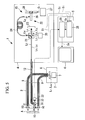
- the light intensity reaches the peak value at two positions (A1 and A2).
- the distance between the positions of the scanning mirror 25 corresponding to the peak values is obtained to calculate the distance from the tip surface 13a of the cover glass 13 at the tip of the insertion portion 3 to the surface of the body tissue A accurately.
- the image processing unit 5 includes a distance calculation correction unit (correction unit, distance calculation unit) 28 and an image composition unit (image forming unit) 29.
- the distance calculation correction unit 28 calculates the distance between the positions of the scanning mirror 25 corresponding to the two peak values at each pixel of the interference image pickup element 23 based on the interference image signal S 2 output from the interference image pickup element 23 and the position information S 1 of the scanning mirror 25 output from the mirror controller 27.
- the distance calculation correction unit 28 is allowed to accurately measure the distance from the tip surface 13a of the cover glass 13 at the tip of the insertion portion 3 to the respective portions on the surface of the body tissue A, and to correct the brightness information of the fluorescent image based on the calculated distance information.
- the brightness information S 3 of the fluorescent image detected by the respective pixels of the pickup element 19 of the image detection unit 14 is inversely proportional to the squared distance from the tip surface of the insertion portion 3 to the respective portions on the surface of the body tissue A. Accordingly, the distance calculation correction unit 28 is structured to multiply the correction coefficient that is proportional to the squared measured distance by the brightness information S 3 of the respective pixels of the fluorescent image. This makes it possible to obtain the fluorescent image information S 4 with the accurate fluorescent quantity on the surface of the body tissue A.
- the image composition unit 29 generates composition image information S 6 by overlapping the actual image information S 5 of the surface of the body tissue A obtained by the pickup element 18 for detecting the white light reflecting on the surface of the body tissue A and the fluorescence image information S 4 corrected by the distance calculation correction unit 28 which have been input.
- the generated information is output to the image display unit 6.
- the tip of the insertion portion 3 is inserted into the body cavity such that the white light L 1 and the excitation light L ex emitted from the light source unit 2, and the measurement light L 5 emitted from the low coherence light source 20 of the detection unit 4 are injected to the insertion portion 3, respectively.
- the white light L 1 and the excitation light L ex emitted from the light source unit 2 are injected to the light guide 9 of the insertion portion 3 and irradiated to the opposite body tissue A within the body cavity opposite the tip surface of the insertion portion 3 from the tip surface of the light guide 9 arranged at the tip of the insertion portion 3.
- the white light L 1 that reflects on the surface of the body tissue A transmits through the cover glass 13 attached to the insertion portion 3 and is collected by the objective lens 11, which is propagated outside the body cavity by the image guide 12.
- the excitation light L ex is irradiated to the body tissue A to excite the fluorescent substance within the body tissue A to generate the fluorescence L 2 .
- the generated fluorescence L 2 transmits through the cover glass 13 attached to the insertion portion 3 so as to be collected by the objective lens 11 and propagated outside the body cavity by the image guide 12.
- the white light L 1 and the fluorescence L 2 propagated outside the body cavity by the image guide 12 are injected to the detection unit 4, they are split from the other light by the first dichroic mirror 16 within the detection unit 4.
- the split white light L 1 and the fluorescence L 2 are further split by the second dichroic mirror 17 so as to be detected by the pickup elements 18 and 19, respectively.
- the actual image information S 5 of the surface of the body tissue A is obtained based on the detected white light L 1
- the brightness information S 3 of the fluorescent image which indicates the site at which the fluorescent substance exists within the body tissue A and the degree of the concentration of the fluorescent substance based on the detected fluorescence L 2 .
- the low coherence light L 3 emitted from the low coherence light source 20 of the detection unit 4 is split into the reference light L 4 and the measurement light L 5 by the beam splitter 21.
- the split measurement light L 5 transmits through the first dichroic mirror 16 to be injected to the image guide 12.
- the measurement light L 5 propagated through the image guide 12 transmits from the tip of the image guide 12 to the objective lens 11 and the cover glass 13 so as to be irradiated to the surface of the body tissue A.
- the measurement light L 5 irradiated to the surface of the body tissue A partially reflects on the surface to transmit through the cover glass 13 and the objective lens 11. It returns to the image guide 12 and propagates therethrough so as to be injected into the detection unit 4.
- the measurement light L 5 transmits through the first dichroic mirror 16 to be split from the white light L 1 and the fluorescence L 2 , and transmits through the beam splitter 21 to be detected by the interference image pickup element 23.
- the reference light L 4 split by the beam splitter 21 is injected to the reference light optical path length adjustment unit 22 and propagated by the optical path length determined in accordance with the position of the scanning mirror 25. It then returns to the beam splitter 21.
- the reference light L 4 is reflected by the beam splitter 21 so as to be detected by the interference image pickup element 23 in the state where it is combined with the measurement light L 5 .
- the reciprocating optical path length of the reference light L 4 from the splitting by the beam splitter 21 of the reference light optical path length adjustment unit 22 to return thereto is set to be substantially the same as that of the measurement light L 5 .
- the mirror controller 27 is operated to allow the mirror movement mechanism 26 to move the scanning mirror 25 in one direction. Then at the position where each reciprocating optical path length of the reference light L 4 and the measurement light L 5 accurately coincides with each other, the light quantity detected by the interference image pickup element 23 reaches the peak value.
- the measurement light L 5 reflects not only on the surface of the body tissue A but also on the tip surface 13a of the cover glass 13 to return as the base light L 6 .
- the interference image information S 2 output from the interference image pickup element 23 reaches the peak value mainly at two positions as shown in Fig. 3.
- the distance calculation correction unit 28 calculates the absolute distance from the tip surface 13a of the cover glass 13 to the body tissue A at each pixel of the interference image pickup element 23 based on the interference image information S 2 sent from the interference image pickup element 23 and the position information S 1 of the scanning mirror 25 sent from the mirror controller 27.
- the distance calculation correction unit 28 calculates the correction coefficient proportional to the squared absolute distance for the respective pixels, and multiplies the correction coefficient by the brightness information S 3 of the fluorescent image sent from the pickup element 19 for each pixel. Then the fluorescent image information S 4 with correct brightness distribution is generated and output to the image composition unit 29.
- the image composition unit 29 synthesizes the actual image information S 5 on the surface of the body tissue A sent from the pickup element 18 with the fluorescent image information S 4 sent from the distance calculation correction unit 28 by overlapping the respective information so as to be output to the image display unit 6.
- the image display unit 6 displays the actual image on the surface of the body tissue A within the body cavity overlapped with the fluorescent image with the correct brightness distribution.
- the image composition unit 29 may be structured to output the actual image information S 5 and the fluorescent image information S 4 independently to the image display unit 6 as necessary. This allows the image display unit 6 to selectively display the actual image within the body cavity, the fluorescent image, and the image both actual image and the fluorescent image overlapped.
- the brightness information S 3 of the fluorescent image obtained by the pickup element 19 is corrected using the absolute distance from the tip surface of the insertion portion 3 to the body tissue A.
- the distance measurement is performed using the low coherence light L 3 such that the optical system for the distance measurement may be commonly used for obtaining the images, thus making the device compact.
- the base light L 6 that returns after reflecting on the tip surface 13a of the cover glass 13 is detected.
- the invention is not limited to the aforementioned structure.
- a reflective film 30 may be formed on the tip surface 13a of the cover glass 13 so as to positively allow the base light L 6 to return after reflecting thereon. This may enhance the intensity of the base light L 6 that returns after reflecting on the tip surface 13a of the cover glass 13, thus allowing further accurate detection of the position of the tip surface 13a.
- the base light L 6 that returns after reflecting on the tip surface 13a of the cover glass 13 is detected.
- a reflective member such as the reflective film may be disposed at the position remote from the tip surface 13a of the cover glass 13 at a known interval to detect the base light L 6 that returns after reflecting the reflective member.
- the detected value may be converted into the distance between the tip surface 13a of the cover glass 13 and the surface of the body tissue A.
- all the white light L 1 , the fluorescence L 2 and the measurement light L 5 returning from the body tissue A are propagated to the detection unit 4 via the image guide 12, and then detected therein.
- the measurement light L 5 may only be returned to the detection unit 4 so as to be detected therein, and the white light L 1 and the fluorescence L 2 may be subjected to the image pickup by the pickup element 32 adjacent to the tip of the insertion portion 3 after being split by the dichroic mirror 31 also adjacent to the tip of the insertion portion 3.
- a reference numeral 33 in the drawing denotes a barrier filter which cuts the excitation light L ex .
- the actual image information S 5 of the white light L 1 and the brightness information S 3 of the fluorescent image of the fluorescence L 2 are output as the electric signals outside the body.
- the distance calculation correction unit 28 receives inputs of the brightness information S 3 of the fluorescent image
- the image composition unit 29 receives the input of the actual image information S 5 of the white light L 1 .
- a filter turret (not shown) with a plurality of filters may be prepared for the light source unit 2 such that the image information is obtained through the frame sequential method.
- the optical system for the distance measurement may be completely separated from the optical system for obtaining the image such that the measurement light L 5 guided from the low coherence light source 20 through the optical fiber (measurement light system) 34 such as the single mode fiber is irradiated to the surface of the body tissue A by an objective lens 35 separated from the object lens 11 for obtaining the image to interfere the measurement light L 5 that returns after reflecting on the surface with the reference light L 4 for measuring the distance.
- the interference image pickup element 36 for detecting the measurement light L 5 may be the photo diode as the optical detector, for example. This makes it possible to improve the resolution of the distance measurement.
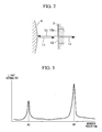
- the arrangement of an optical scanner 37 such as the scan mirror for two-dimensionally scanning the measurement light L 5 radiated from the tip of the optical fiber 34 allows the two-dimensional measurement of the distance between the tip surface of the insertion portion 3 and the surface of the body tissue A as shown in Fig. 7.
- the mirror controller 27 is operated to control the scanning position performed by the optical scanner 37, and the position information S 6 relevant thereto is also transmitted to the distance calculation correction unit 28. The distance between the insertion portion 3 and the body tissue A at the corresponding position may be calculated accurately.
- the tip of the insertion portion 3 is provided with the low coherence light source 20, the beam splitter 21, the interference image pickup element 36, the scanning mirror 25 and the mirror movement unit 26 as shown in Fig. 8, the measurement light L 5 does not have to be propagated for an elongated distance. This also makes it possible to obtain all the detected image information S 2 , S 3 and S 5 as the electric signals outside the body.
- the measurement light L 5 is propagated by the optical fiber 34 such as the single mode fiber.
- the white light L 1 , the excitation light L ex and the measurement light L 5 may be guided to the tip of the insertion portion 3 by the optical fiber 34 such as the single mode fiber so as to be two-dimensionally scanned by the optical scanner 37 like the scan mirror attached to the tip of the insertion portion 3 as shown in Fig. 9. This makes it possible to make all the optical systems commonly used, resulting in the compact structure.
- the endoscope observation device 40 of the embodiment is different from the endoscope observation device 1 according to the first embodiment in the structure of the reference light optical path length adjustment unit 41.
- the reference light optical path length adjustment unit (optical path length adjustment unit) 41 includes a plurality of beam splitters (reference light split unit) 42, 43 and a mirror 44 for splitting the reference light L 4 propagated by the fiber bundle 24 into a plurality of lights, a plurality of scanning mirrors 25 which reflect the respective split reference lights L 4 , a plurality of mirror movement mechanisms 26 that move those scanning mirrors 25, respectively, a plurality of beam splitters 45, 46 and a mirror 47 for splitting the measurement light L 5 and the base light L 6 which have transmitted through the beam splitter 21 after returning from the insertion portion 3 into a plurality of lights, a plurality of beam splitters 48 to 50 that combine the plurality pairs of the reference light L 4 , the measurement light L5 and the base light L 6 which have been split by those beam splitters 42, 43, 45 and 46, and a plurality of interference image pickup elements 23 that detect the plurality of pairs of the reference light L 4 , the measurement light L 5 and the base light L 6 that have been combined through the
- the optical path length on which the measurement light L 5 split by the beam splitter 21 is irradiated to the surface of the body tissue A via the image guide 12, returns after reflecting via the image guide 12, transmits through the first dichroic mirror 16 and the beam splitter 21, and reaches the respective beam splitters 45, 46 or the mirror 47 after being reflected by the respective beam splitters 45, 46 or the mirror 47 is set to be different.
- the optical path length on which the reference light L 4 split by the beam splitter 21 transmits through the fiber bundle 24 to be reflected by the beam splitters 42, 43 or the mirror 44, further transmits through the beam splitters 48 to 50 to be turned at the respective scanning mirrors 25 to reach the respective beam splitters 48 to 50 is set to be substantially the same as that of the measurement light L 5 that reaches the same beam splitters 48 to 50.
- Each range of the optical path length of the reference light L 4 adjusted by the respective scanning mirrors 25 is set to be adjacent with each other with no gap.
- the range of the optical path length of the reference light L 4 adjusted by the respective scanning mirror 25 may be adjacent with each other without being overlapped. Alternatively, the range may be overlapped.
- the endoscope observation device 40 is provided with a plurality of interference image pickup elements 23 to allow a plurality of the interference image pickup elements 23 to cover the range of the distance measurement from the tip of the insertion portion 3 to the surface of the body tissue A. Accordingly, the range for the distance measurement may be increased without enlarging the optical path length adjustment range of the reference light L 4 by the respective scanning mirrors 25. As a result, the displacement range of the scanning mirror 25 may be reduced to make the time required for measuring the distance short, thus accelerating the image processing.
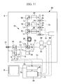
- the endoscope observation device 60 of the embodiment is different from the endoscope observation device 40 according to the second embodiment in the structure of the reference light optical path length adjustment unit 61 as shown in Fig. 11.
- the reference light optical path length adjustment unit (optical path length adjustment unit) 61 includes a plurality of beam splitters 62, 63 and a mirror 64 for splitting the reference light L 4 propagated by the fiber bundle 24 into a plurality of lights, optical modulators 65 to 67 for modulating the plurality of split reference lights L 4 at the different frequencies, a plurality of scanning mirrors 25 which reflect the modulated split reference lights L 4 , a plurality of mirror movement mechanisms 26 that move those scanning mirrors 25, respectively, a spectrum analyzer (frequency detector) 68 for subjecting the output signal from the interference image pickup element 23 to the frequency analysis, and a reference light identifying unit 69 for identifying the reference light L 4 that causes the interference in accordance with the frequency analysis result S 7 performed by the spectrum analyzer 68.
- a reference numeral 70 in the drawing denotes a filter.
- Each optical path length on which the reference lights L 4 split by the beam splitter 21 transmits through the fiber bundle 24 to be reflected by the beam splitters 62, 63 or the mirror 64, transmits through the respective optical modulators 65 to 67 to be turned by the respective scanning mirrors 25 to reach the beam splitter 21 on the same optical path is set to be different.
- Each range of the optical path length of the reference lights L 4 adjusted by the respective scanning mirrors 25 is set to be adjacent with each other with no gap.
- the range of the optical path length of the reference light L 4 adjusted by the respective scanning mirrors 25 may be adjacent with each other without being overlapped. However, the ranges may be overlapped with each other.
- the reference light L 4 split by the beam splitter 21 to transmit through the fiber bundle 24 is reflected by the beam splitters 62, 63 or the mirror 64 so as to be split into a plurality of, for example, three lights. Each split light is frequency modulated by the corresponding optical modulators 65 to 67 at the different frequency. Thereafter, the plurality of the reference lights L 4 are reflected by the respective scanning mirrors 25 to return on the same path. In the aforementioned process, the plurality of the reference lights L 4 are combined by the beam splitters 62 and 63, and transmit through the fiber bundle 24 to reach the beam splitter 21. The combined reference light L 4 is further combined with the measurement light L 5 and the base light L 6 returning from the insertion portion 3 in the beam splitter 21 so as to be detected by the interference image pickup element 23.
- the reference light L 4 that reaches the interference image pickup element 23 is synthesized with the reference light L 4 reflected by the plurality of scanning mirrors 25 to be propagated through the plurality of optical paths each having the different length.
- the reference lights L 4 passing through the respective optical paths are modulated to have different frequencies, and subjected to the frequency analysis by the spectrum analyzer 68 after being detected by the interference image pickup element 23.
- the reference light identifying unit 69 determines as to which frequency of the interference image subjected to the frequency analysis by the spectrum analyzer 68 has a peak value such that the reference light L 4 that causes the interference may be easily identified.
- the distance between the tip surface of the insertion portion 3 and the surface of the body tissue A may be accurately measured.
- the distance measurement range may be greatly enlarged without increasing the range where each of the scanning mirrors 25 displaces.
- the structure of the endoscope observation device 60 has the simple structure compared with that of the endoscope observation device 40 of the second embodiment as the single interference image pickup element 23 detects the measurement light L 5 and the base light L 6 without being split, resulting in the compact structure.
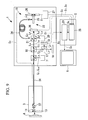
- An endoscope observation device 80 according to a fourth embodiment will be described referring to Fig. 12.
- the endoscope observation device 80 of the embodiment includes a probe 82 to be inserted into a forceps channel 81 of the long and thin insertion portion 3, and an optical fiber (measurement optical system) 83 connected to the probe 82 and the detection unit 4 such as the single mode fiber.
- a mirror (light emitting portion, light receiving portion) 84 that bends the optical axis at 90° is attached to the tip of the probe 82.
- the probe 82 further includes a rotator 85 that rotates the probe 82 at 360° around its axis and a probe controller 86 that controls the rotator 85.
- the detection unit 4 includes an excitation light source 87 that emits the excitation light L ex , a first dichroic mirror 88 that injects the excitation light L ex from the excitation light source 87, a second dichroic mirror 89 that splits the fluorescence L 2 returning from the probe 82, an optical detector 90 that detects the fluorescence L 2 and a distance measurement unit 15.
- the optical detector 90 formed of a device for detecting the brightness of the fluorescence L 2 such as a photo diode is employed to obtain the strip-shaped image over the entire periphery using the brightness information S 3 of the fluorescence L 2 obtained at each rotational angular position of the mirror 84 at the tip of the probe 82, and the rotational angular position information S 8 of the mirror 84 at that time.
- the insertion portion 3 that has been inserted into a body cavity B is moved along its axis as a whole or the movement mechanism 91 is operated to move the probe 82 in the axial direction with respect to the insertion portion 3 such that a plurality of the strip-shaped images over the entire periphery are obtained while being shifted in the axial direction. This makes it possible to obtain the fluorescent image over the wide range in the axial direction.
- the distance measurement unit 15 which is the same as the one shown in Fig. 1 employs a glass plate 92 for extending the actual optical path length in place of the fiber bundle 24 for keeping the optical path length of the reference light L 4 , thus realizing the compact structure.
- a detector 93 of the distance measurement unit 15 is formed of a photo diode, for example.
- An optical modulator 94 is disposed between the glass plate 92 and the scanning mirror 25.
- An acoustic optical modulator (AOM) or an electric optical modulator (EOM) may be employed as the optical modulator 94.
- the optical modulator 94 changes the frequency of the reference light L 4 to be different from those of the measurement light L 5 and the base light L 6 for the purpose of causing the beat in the light formed by combining the reference light L 4 , the measurement light L 5 and the base light L 6 .
- the maximum frequency component of the combined light is proportional to the value obtained by multiplying the scanning frequency of the scanning mirror 25 by the width of the tomogram of the obtained specimen in the depth direction and the inverse number of the resolution value.
- the optical modulator 94 may be disposed on the optical path of the measurement light L 5 .
- a band-pass filter (not shown) for extracting the signal at the beating frequency from the interference brightness information S 2 is provided at the side where the interference brightness information S 2 is input from the distance calculation correction unit 28 in the image processing unit 5.
- the excitation light L ex emitted from the excitation light source 87 is reflected by the first dichroic mirror 88 and injected to the optical fiber 83.
- the excitation light L ex injected to the optical fiber 83 propagates therethrough and is injected to the probe 82. It is bent at 90° by the mirror 84 at the tip of the probe 82 to be radiated in the lateral direction. It is then irradiated to the inner wall surface of the laterally positioned body cavity B.
- the fluorescence L 2 generated by irradiation of the excitation light L ex returns into the optical fiber 83 via the mirror 84 at the tip of the probe 82.
- the fluorescence L 2 that has been returned into the optical fiber 83 propagates therethrough and transmits through the first dichroic mirror 88. It is reflected by the second dichroic mirror 89 to be detected by the optical detector 90.
- the brightness information S 3 generated through detection of the fluorescence L 2 by the optical detector 90 is transmitted to the distance calculation correction unit 28 together with the rotational angular position information S 8 of the probe 82 output from the probe controller 86.
- the light obtained by combining the reference light L 4 , the measurement light L 5 and the base light L 6 is detected by the detector 93 to allow the interference brightness information S 2 sent from the detector 93 is transmitted to the distance calculation correction unit 28 together with the position information S 1 of the scanning mirror 25 such that the distance between the tip surface of the probe 82 and the inner wall surface of the body cavity B is calculated.
- the light obtained by combining the reference light L 4 , the measurement light L 5 and the base light L 6 exhibits the beat owing to the change in the frequency of the reference light L 4 modulated by the optical modulator 94.
- the interference brightness information S 2 sent from the detector 93 is input to the image processing unit 5 in the presence of the beat, and transmitted to the distance calculation correction unit 28 after extraction of the component of the beating frequency by the band-pass filter so as to be used for calculating the distance.
- the fluorescent brightness information S 3 sent from the optical detector 90 is corrected based on the calculated distance, which will be accumulated in the image composition unit 29.
- the brightness information S 3 of the fluorescence L 2 obtained at each rotational angular position during the rotation of the probe 82 at 360° is accumulated in the image composition unit 29 after the correction based on the distance calculated at each time. This makes it possible to generate the strip-shaped fluorescent image information with the correct brightness over the entire periphery.
- the fluorescent image in a predetermined range along the axis may be obtained.
- the band-pass filter extracts the component of the beating frequency generated by the optical modulator 94 from the interference brightness information S 2 , the component of the signal relevant to the interference of the reference light L 4 , the measurement light L 5 and the base light L 6 may be extracted from the interference brightness information S 2 such that the other noise component may be eliminated.
- the probe 82 having the mirror 84 attached to its tip is rotated around its axis. It may be structured to have the optical fiber 83 fixed as shown in Fig. 14 such that the mirror 84 obliquely arranged opposite the end surface of the end surface of the optical fiber 83 is rotated around its axis by the actuator such as a hollow motor 95, for example.
- a conical mirror 96 as shown in Fig. 15 may be attached to the opposite tip of a fiber bundle 83' so as to obtain the fluorescent image over the entire periphery at a time.
- the invention may be applied to the observation device equipped with no insertion portion 3 (not shown).
- An endoscope observation device 100 according to a fifth embodiment of the invention will be described referring to Figs. 16 and 17.
- the endoscope observation device 100 of the embodiment includes a probe 82 to be inserted into a forceps channel 81 of the long and thin insertion portion 3, an optical fiber 83 that propagates the light from the detection unit 4 to the probe 82, and a semi-transmissive film (base light split unit) 101 attached to the tip of the optical fiber 83 at the intermediate position of the probe 82 in the longitudinal direction.
- a semi-transmissive film (base light split unit) 101 attached to the tip of the optical fiber 83 at the intermediate position of the probe 82 in the longitudinal direction.
- the semi-transmissive film 101 splits part of the low coherence light L 3 emitted from the low coherence light source 20 and guided by the optical fiber 83 as the base light L 6 , and the measurement light L 5 as the rest of the low coherence light L 3 , which are allowed to transmit so as to be guided to the body cavity B as the specimen.
- the semi-transmissive film 101 is attached to the tip surface of the optical fiber 83.
- a half mirror 102 may be provided on the optical path of the measurement optical system as the reference light split unit.
- a reference numeral 103 denotes a collimated lens
- a reference numeral 104 denotes a coupling lens.
- the distance measurement unit 15 includes a low coherence light source 20, a first beam splitter 105 that reflects the low coherence light L 3 emitted from the low coherence light source 20 to guide the light to the optical fiber 83 while transmitting the measurement light L 5 and the base light L 6 returning from the optical fiber 83, a second beam splitter (interference light split unit: optical coupler) 106 that splits the measurement light L 5 and the base light L 6 which have been transmitted through the first beam splitter 105 into two interference optical paths, that is, the first and the second interference optical paths L A and L B , an optical path length difference adjustment unit 107 that is disposed on the first interference optical path L A for adjusting the difference in the optical path length between those two interference optical paths L A and L B , a mirror 108 that is disposed on the second interference optical path L B for returning the measurement light L 5 and the base light L 6 through reflection, and a detector 109 that detects the measurement light L 5 and the base light L 6 which have returned to the second beam splitter
- the optical path length difference adjustment unit 107 includes the scanning mirror 25 that returns the measurement light L 5 and the base light L 6 split to the first interference optical path L A by the second bema splitter 106 thereto, the mirror movement mechanism (mirror movement unit) 26 that moves the scanning mirror 25 along the first interference optical path L A , and the mirror controller 27 that controls the mirror movement mechanism 26 and outputs the position information S 1 of the scanning mirror 25.
- the scanning mirror 25 is structured to reciprocally move between the position where the optical path length D 1 with respect to the second beam splitter 106 becomes equal to the optical path length D 2 from the second beam splitter 106 to the mirror 108 and the position where the optical path length D 1 becomes longer than the optical path length D 2 by the length D 3 from the semi-transmissive film 101 to the inner surface of the body cavity B via the mirror 84.
- This makes it possible to measure the optical path length D 3 between the semi-transmissive film 101 and the inner surface of the body cavity B as the difference between the optical path length D 1 of the first interference optical path L A and the second optical path length D 2 of the second interference optical path L B .
- the mirror movement mechanism 26 is operated to perform the positional adjustment of the scanning mirror 25 such that the base light L 6 returned to the second beam splitter 106 through the first interference optical path L A interferes with the measurement light L 5 returned to the second beam splitter 106 through the second interference optical path L B when the difference between the optical path length D 1 of the first interference optical path L A and the optical path length D 2 of the second interference optical path L B coincides with the optical path length D 3 from the semi-transmissive film 101 to the inner surface of the body cavity B via the mirror 84.
- the base lights L 6 each passing through the respective interference optical paths L A and L B are expected to cause the interference.
- the light intensity detected by the detector 109 reaches the peak value.
- the second interference optical path L B between the second beam splitter 106 and the mirror 108 includes an optical modulator 110 for modulating each frequency of the measurement light L 5 and the base light L 6 passing through the second interference optical path L B .
- the optical modulator 110 changes the frequency of the light passing through the second interference optical path LB so as to be different from that of the light passing through the first interference optical path L A in order to cause the beat in the light obtained by combining the base light L 6 passing through the first interference optical path L A and the measurement light L 5 passing through the second interference optical path L B , and the light obtained by combining the base lights L 6 each passing through those two interference optical paths L A and L B .
- the optical modulator 110 may be disposed at the intermediate position of the first interference optical path L A .
- the image processing unit 5 is provided with the band-pass filter (not shown) for extracting the signal of the beating frequency from the interference brightness information S 2 at the side where the interference brightness information S 2 is input from the distance calculation correction unit 28.
- the distance calculation correction unit 28 is provided with a memory (not shown) that preliminarily stores the optical path length D 2 of the second interference optical path L B and an optical path length D 4 from the semi-transmissive film 101 to the tip surface of the probe 82.
- the distance calculation correction unit 28 calculates the difference between the optical path length D 1 of the first interference optical path L A and the optical path length D 2 of the second interference optical path L B at a time point when the interference occurs between the base light L 6 passing through the first interference optical path L A and the measurement light L 5 passing through the second interference optical path L B in the second beam splitter 106.
- the absolute distance between the tip surface of the probe 82 and the body cavity B may be calculated based on the value obtained by subtracting the optical path length D 4 stored in the memory from the calculated difference.
- the distance calculation correction unit 28 is structured to calculate the optical path length D 1 of the first interference optical path L A based on the position information S 1 of the scanning mirror 25 output from the mirror controller 27. Then the optical path length D 2 of the second interference optical path LB and the optical path length D 4 from the semi-transmissive film 101 to the tip surface of the probe 82 are read from the memory, and the sum of the optical path lengths of D 2 and D 4 is subtracted from the calculated optical path length D 1 .
- the distance calculation correction unit 28 is capable of calculating the absolute distance from the tip surface of the probe 82 and the body cavity B.
- the excitation light L ex emitted from the excitation light source 87 is reflected by the first dichroic mirror 88 to be injected into the optical fiber 83.
- the excitation light L ex injected into the optical fiber 83 propagates therethrough to be injected to the probe 82. It is bent at 90° by the mirror 84 attached to the tip of the probe 82 and laterally radiated to the inner wall surface of the body cavity B arranged in the lateral direction.
- the fluorescence L 2 generated through irradiation of the excitation light L ex returns into the optical fiber 83 via the mirror 84 at the tip of the probe 82.
- the fluorescence L 2 returned into the optical fiber 83 propagates therethrough and transmits the first dichroic mirror 88. It is reflected by the second dichroic mirror 89 to be detected by the optical detector 90.
- the brightness information S 3 generated through detection of the fluorescence L 2 by the optical detector 90 is transmitted to the distance calculation correction unit 28 together with the rotational angular position information S 8 of the probe 82 output from a probe controller 86.
- the low coherence light L 3 emitted from the low coherence light source 20 of the detection unit 4 is reflected by the first beam splitter 105 and further injected into the probe 82.
- the low coherence light L 3 propagated through the probe 82 is partially reflected by the semi-transmissive film 101 to be formed as the base light L 6 , and the rest of the low coherence light is formed as the measurement light L 5 that transmits through the semi-transmissive film 101 to be irradiated to the inner surface of the body cavity B.
- the base light L 6 reflected on the semi-transmissive film 101 and the measurement light L 5 returned after reflecting on the inner surface of the body cavity B transmit through the first beam splitter 105, and are split into two interference optical paths, that is, the first and the second optical paths L A and L B by the second beam splitter 106.
- the measurement light L 5 and the base light L 6 guided through the first interference optical path L A are reflected by the scanning mirror 25 of the optical path length difference adjustment unit 107, and return to the second beam splitter 106 again.
- the measurement light L 5 and the base light L 6 guided through the second interference optical path L B have the respective frequencies changed through passage of the optical modulator 110. They are reflected by the mirror 108 to return to the second beam splitter 106 again.
- the optical path length D 1 of the first interference optical path L A accurately coincides with the sum of the optical path length D 2 of the second interference optical path LB and the optical path length D 3 from the semi-transmissive film 101 to the inner surface of the body cavity B
- the optical path length of the measurement light L5 which is reflected on the inner surface of the body cavity B and injected into the second beam splitter 106 through the second interference optical path L B coincides with the optical path length of the base light L 6 which is split through the semi-transmissive film 101 and injected to the second beam splitter 106 through the first interference optical path L A .
- the optical path length D 1 accurately coincides with the optical path length D 2
- the optical path length of the base light L 6 injected into the second beam splitter 106 through the second interference optical path L B coincides with the optical path length of the base light L 6 injected into the second beam splitter 106 through the first interference optical path L A .
- the positional adjustment of the scanning mirror 25 is performed such that the measurement light L 5 and the base light L 6 each passing through the second interference optical path L B are interfered with the base light L 6 passing through the first interference optical path L A in the second beam splitter 106.
- the light intensity signal S 2 detected by the detector 109 reaches the peak value. Accordingly, the light intensity signal S 2 reaches the peak value twice as the position of the scanning mirror 25 is changed.
- the distance calculation correction unit 28 calculates the distance between two positions of the scanning mirrors 25 corresponding to the two peak values based on the position information S 1 of the scanning mirror 25 such that the optical path length D 3 from the semi-transmissive film 101 to the inner surface of the probe 82 is calculated. Then the distance calculation correction unit 28 reads the optical path length D 4 from the semi-transmissive film 101 to the tip surface of the probe 82 from the memory, and subtracts the optical path length D 4 from the calculated optical path length D 3 .
- the distance calculation correction unit 28 is capable of calculating the absolute distance between the tip surface of the probe and the inner surface of the body cavity B.
- the distance calculation correction unit 28 corrects the brightness information S 3 of the fluorescence L 2 detected by the optical detector 90 based on the calculated absolute distance.
- the corrected information is accumulated in the image generation unit 29.
- the brightness information S 3 of the fluorescence L 2 obtained at the respective rotational angular positions while rotating the probe at 360° is corrected based on the calculated distance, and accumulated in the image forming unit 29. This makes it possible to generate the strip-shaped fluorescent image information with the correct brightness over the entire periphery.
- the band-pass filter serves to extract the component of the beating frequency generated by the optical modulator 94 from the interference brightness information S 2 .
- the component of the signal relevant to the interference of the measurement light L 5 and the base light L 6 each passing through the second interference optical path L B with the base light L 6 passing through the first interference optical path L A is only extracted from the interference brightness information S 2 so as to eliminate the other component of noise.
- the absolute distance between the tip surface of the probe 82 and the inner surface of the body cavity B is obtained based on the distance between two positions of the scanning mirrors 25 corresponding to the two peak values generated in the optical intensity signal S 2 detected by the detector 109.
- the following process may be employed for calculating the absolute distance.
- the optical path length D 1 from the scanning mirror 25 to the second beam splitter 106 accurately coincides with the sum of the optical path length D 2 from the second beam splitter 106 to the mirror 108 and the optical path length D 3 from the semi-transmissive film 101 to the inner surface of the body cavity B
- the optical path length of the measurement light L 5 injected into the second beam splitter 106 through the second interference optical path LB coincides with the optical path length of the base light L 6 injected into the second beam splitter 106 through the first interference optical path L A .
- the calculation may be performed by replacing the optical path length D 3 between the semi-transmissive film 101 and the body cavity B with the difference between the optical path lengths D 1 and D 2 .
- the optical path length D 1 from the scanning mirror 25 to the second beam splitter 106 may only be obtained for calculating the absolute distance between the tip surface of the probe 82 and the inner surface of the body cavity B.
- the scanning mirror 25 is arranged only at the position at which the optical path length D 1 accurately coincides with the sum of the optical path lengths D 2 and D 3 .
- the information of the optical path lengths D 2 and D 4 is stored in the memory (not shown) of the distance calculation correction unit 28.
- the scanning mirror 25 is subjected to the positional adjustment such that the measurement light L 5 passing through the second interference optical path L B is interfered with the base light L 6 passing through the first interference optical path L A in the second beam splitter 106.
- the optical intensity signal detected by the detector 109 reaches the peak value.
- the optical intensity signal S 2 detected by the detector 109 is transmitted to the distance calculation correction unit 28 together with the position information S 1 of the scanning mirror 25.
- the distance calculation correction unit 28 calculates the difference between the lengths of two interference optical paths L A and L B at a time point when the base light L 6 passing through the first interference optical path L A is interfered with the measurement light L 5 passing through the second interference optical path L B in the second beam splitter 106.
- the distance calculation correction unit 28 calculates the optical path length D 1 of the first interference optical path L A based on the position information S 1 of the scanning mirror 25 at a time point when the measurement light L 5 passing through the second interference optical path L B is interfered with the base light L 6 passing through the first interference optical path L A .
- the distance calculation correction unit 28 reads the optical path length D 2 of the second interference optical path L B and the optical path length D 4 from the semi-transmissive film 101 to the tip surface of the probe 82 from the memory, and subtracts the sum of the optical path lengths D 2 and D 4 from the calculated optical path length D 1 .
- the distance calculation correction unit 28 is capable of calculating the absolute distance between the tip surface of the probe 82 and the inner surface of the body cavity B.
- the position information S 1 of the single scanning mirror 25 is only detected to allow calculation of the absolute distance between the tip surface of the probe 82 and the inner surface of the body cavity B, thus reducing the operation range of the scanning mirror 25. Accordingly, the absolute distance may further be easily calculated.
- the semi-transmissive film 101 is attached to the tip surface of the optical fiber 83 disposed at the intermediate position of the probe 82 in the longitudinal direction. Alternatively, it may be arranged at the tip surface of the probe 82.
- the optical path length difference adjustment unit 107 is disposed on the first interference optical path L A .
- it may be disposed on the second interference optical path L B .
- the semi-transmissive film 101 may be used for splitting the reference light L 4 and the absolute distance from the tip surface of the probe 82 to the inner surface of the body cavity B is calculated using the base light L 6 that returns after reflecting on the tip surface (for example, the tip surface of the cover glass) of the probe 82.
- the reference light L 4 , the measurement light L 5 and the base light L 6 return to the two interference optical paths L A and LB, respectively.
- the difference in the optical path length D 1 of the first interference optical path L A between the interference of the reference light L 4 with the measurement light L 5 and the interference of the reference light L 4 with the base light L 6 is calculated to accurately obtain the absolute distance between the tip surface of the probe 82 and the inner surface of the body cavity B.
- the optical path length D 2 of the second interference optical path L B and the position information of the semi-transmissive film 101 for splitting the reference light L 4 do not have to be stored.
- the required accuracy for installing the semi-transmissive film 101 or the mirror 108 is not so strict. This makes it possible to easily produce the device as well as simplify arithmetic processing.
- the interference light with high intensity may be obtained by enhancing the intensity of the reference light L 4 interfered with the measurement light L 5 and the base light L 6 . This makes it possible to improve the accuracy of the arithmetic operation of the absolute distance.
- the aforementioned structure allows the optical path of the reference light L 4 to be disposed within the probe 82, thus reducing the size of the detection unit 4 and further making the endoscope observation device 100 compact.
Priority Applications (1)
| Application Number | Priority Date | Filing Date | Title |
|---|---|---|---|
| EP10012568.1A EP2263517B1 (fr) | 2006-02-23 | 2007-02-21 | Dispositif d'observation endoscopique |
Applications Claiming Priority (1)
| Application Number | Priority Date | Filing Date | Title |
|---|---|---|---|
| JP2006046639A JP5044126B2 (ja) | 2006-02-23 | 2006-02-23 | 内視鏡観察装置および画像形成を行う内視鏡の作動方法 |
Related Child Applications (2)
| Application Number | Title | Priority Date | Filing Date |
|---|---|---|---|
| EP10012568.1A Division-Into EP2263517B1 (fr) | 2006-02-23 | 2007-02-21 | Dispositif d'observation endoscopique |
| EP10012568.1A Division EP2263517B1 (fr) | 2006-02-23 | 2007-02-21 | Dispositif d'observation endoscopique |
Publications (3)
| Publication Number | Publication Date |
|---|---|
| EP1829473A2 true EP1829473A2 (fr) | 2007-09-05 |
| EP1829473A3 EP1829473A3 (fr) | 2007-11-07 |
| EP1829473B1 EP1829473B1 (fr) | 2014-04-23 |
Family
ID=38279224
Family Applications (2)
| Application Number | Title | Priority Date | Filing Date |
|---|---|---|---|
| EP10012568.1A Expired - Fee Related EP2263517B1 (fr) | 2006-02-23 | 2007-02-21 | Dispositif d'observation endoscopique |
| EP07003573.8A Expired - Fee Related EP1829473B1 (fr) | 2006-02-23 | 2007-02-21 | Dispositif d'observation endoscopique |
Family Applications Before (1)
| Application Number | Title | Priority Date | Filing Date |
|---|---|---|---|
| EP10012568.1A Expired - Fee Related EP2263517B1 (fr) | 2006-02-23 | 2007-02-21 | Dispositif d'observation endoscopique |
Country Status (3)
| Country | Link |
|---|---|
| US (1) | US7967743B2 (fr) |
| EP (2) | EP2263517B1 (fr) |
| JP (1) | JP5044126B2 (fr) |
Cited By (6)
| Publication number | Priority date | Publication date | Assignee | Title |
|---|---|---|---|---|
| EP2505989A1 (fr) * | 2011-03-30 | 2012-10-03 | Karl Storz GmbH & Co. KG | Dispositif destiné au diagnostic par fluorescence |
| EP2589328A1 (fr) * | 2010-07-02 | 2013-05-08 | Olympus Corporation | Appareil de traitement d'image et procédé de traitement d'image |
| CN104146711A (zh) * | 2014-08-01 | 2014-11-19 | 深圳市开立科技有限公司 | 一种基于内窥镜的病灶尺寸测量方法和系统 |
| EP2588001A4 (fr) * | 2010-06-29 | 2016-01-20 | Mcneil Ppc Inc | Procédé de nettoyage de la cavité buccale |
| EP2588000A4 (fr) * | 2010-06-29 | 2016-01-20 | Mcneil Ppc Inc | Procédé de nettoyage de la cavité buccale |
| WO2016181076A1 (fr) | 2015-05-12 | 2016-11-17 | Commissariat à l'énergie atomique et aux énergies alternatives | Procédé de correction d'une image de fluorescence |
Families Citing this family (67)
| Publication number | Priority date | Publication date | Assignee | Title |
|---|---|---|---|---|
| JP5461753B2 (ja) | 2004-07-30 | 2014-04-02 | オリンパス株式会社 | 内視鏡装置 |
| JP2008043396A (ja) * | 2006-08-11 | 2008-02-28 | Olympus Corp | 内視鏡システム |
| JP5314841B2 (ja) * | 2006-08-22 | 2013-10-16 | オリンパス株式会社 | 内視鏡装置、及び内視鏡プローブ |
| US9079762B2 (en) * | 2006-09-22 | 2015-07-14 | Ethicon Endo-Surgery, Inc. | Micro-electromechanical device |
| JP2008148791A (ja) * | 2006-12-14 | 2008-07-03 | Olympus Corp | 内視鏡システム |
| US7713265B2 (en) | 2006-12-22 | 2010-05-11 | Ethicon Endo-Surgery, Inc. | Apparatus and method for medically treating a tattoo |
| US8273015B2 (en) | 2007-01-09 | 2012-09-25 | Ethicon Endo-Surgery, Inc. | Methods for imaging the anatomy with an anatomically secured scanner assembly |
| US8801606B2 (en) * | 2007-01-09 | 2014-08-12 | Ethicon Endo-Surgery, Inc. | Method of in vivo monitoring using an imaging system including scanned beam imaging unit |
| US8216214B2 (en) * | 2007-03-12 | 2012-07-10 | Ethicon Endo-Surgery, Inc. | Power modulation of a scanning beam for imaging, therapy, and/or diagnosis |
| JP5118867B2 (ja) * | 2007-03-16 | 2013-01-16 | オリンパス株式会社 | 内視鏡観察装置および内視鏡の作動方法 |
| US20080242967A1 (en) * | 2007-03-27 | 2008-10-02 | Ethicon Endo-Surgery, Inc. | Medical imaging and therapy utilizing a scanned beam system operating at multiple wavelengths |
| US7995045B2 (en) * | 2007-04-13 | 2011-08-09 | Ethicon Endo-Surgery, Inc. | Combined SBI and conventional image processor |
| US8626271B2 (en) * | 2007-04-13 | 2014-01-07 | Ethicon Endo-Surgery, Inc. | System and method using fluorescence to examine within a patient's anatomy |
| US20080275305A1 (en) * | 2007-05-01 | 2008-11-06 | Ethicon Endo-Surgery, Inc. | Medical scanned beam imager and components associated therewith |
| US8160678B2 (en) | 2007-06-18 | 2012-04-17 | Ethicon Endo-Surgery, Inc. | Methods and devices for repairing damaged or diseased tissue using a scanning beam assembly |
| JP5036423B2 (ja) * | 2007-06-28 | 2012-09-26 | 株式会社キーエンス | 画像撮像装置 |
| US7558455B2 (en) | 2007-06-29 | 2009-07-07 | Ethicon Endo-Surgery, Inc | Receiver aperture broadening for scanned beam imaging |
| US7982776B2 (en) | 2007-07-13 | 2011-07-19 | Ethicon Endo-Surgery, Inc. | SBI motion artifact removal apparatus and method |
| US9125552B2 (en) | 2007-07-31 | 2015-09-08 | Ethicon Endo-Surgery, Inc. | Optical scanning module and means for attaching the module to medical instruments for introducing the module into the anatomy |
| US7983739B2 (en) * | 2007-08-27 | 2011-07-19 | Ethicon Endo-Surgery, Inc. | Position tracking and control for a scanning assembly |
| US7925333B2 (en) * | 2007-08-28 | 2011-04-12 | Ethicon Endo-Surgery, Inc. | Medical device including scanned beam unit with operational control features |
| US20090060381A1 (en) * | 2007-08-31 | 2009-03-05 | Ethicon Endo-Surgery, Inc. | Dynamic range and amplitude control for imaging |
| US8582934B2 (en) | 2007-11-12 | 2013-11-12 | Lightlab Imaging, Inc. | Miniature optical elements for fiber-optic beam shaping |
| US7813609B2 (en) | 2007-11-12 | 2010-10-12 | Lightlab Imaging, Inc. | Imaging catheter with integrated reference reflector |
| US8050520B2 (en) | 2008-03-27 | 2011-11-01 | Ethicon Endo-Surgery, Inc. | Method for creating a pixel image from sampled data of a scanned beam imager |
| US8332014B2 (en) | 2008-04-25 | 2012-12-11 | Ethicon Endo-Surgery, Inc. | Scanned beam device and method using same which measures the reflectance of patient tissue |
| JP5190944B2 (ja) * | 2008-06-26 | 2013-04-24 | 富士フイルム株式会社 | 内視鏡装置および内視鏡装置の作動方法 |
| WO2010047190A1 (fr) | 2008-10-20 | 2010-04-29 | コニカミノルタオプト株式会社 | Sonde optique rotative |
| JP5429447B2 (ja) * | 2008-10-29 | 2014-02-26 | コニカミノルタ株式会社 | 光断層画像測定装置 |
| AU2009318141B2 (en) * | 2008-11-18 | 2014-05-22 | Stryker Corporation | Endoscopic LED light source having a feedback control system |
| JP5393216B2 (ja) * | 2009-03-24 | 2014-01-22 | オリンパス株式会社 | 蛍光観察システムおよび蛍光観察システムの作動方法 |
| US20120249764A1 (en) * | 2009-08-07 | 2012-10-04 | Ruben Kuon | Cervical, fetal-membrane, and amniotic examination and assessment device and method |
| KR101076757B1 (ko) * | 2009-12-17 | 2011-10-26 | (주)프로옵틱스 | 동축조명 내시경 광학계 |
| WO2011115095A1 (fr) * | 2010-03-18 | 2011-09-22 | オリンパス株式会社 | Dispositif d'observation de fluorescence et procédé d'observation de fluorescence |
| WO2012018796A2 (fr) * | 2010-08-02 | 2012-02-09 | The Johns Hopkins University | Système et endoscope avec focalisation automatique |
| KR101840312B1 (ko) * | 2010-08-02 | 2018-03-20 | 더 존스 홉킨스 유니버시티 | 협동 로봇 제어 및 음향 피드백을 사용하여 힘 센서 정보를 나타내기 위한 방법 |
| WO2012053160A1 (fr) * | 2010-10-21 | 2012-04-26 | パナソニック株式会社 | Dispositif d'essai échographique et procédé d'essai échographique |
| US20130310645A1 (en) * | 2011-01-28 | 2013-11-21 | Koninklijke Philips N.V. | Optical sensing for relative tracking of endoscopes |
| AU2012262258B2 (en) | 2011-05-31 | 2015-11-26 | Lightlab Imaging, Inc. | Multimodal imaging system, apparatus, and methods |
| JP5727326B2 (ja) * | 2011-08-02 | 2015-06-03 | 株式会社トプコン | 光断層画像化装置およびその動作制御方法 |
| JP5926909B2 (ja) | 2011-09-07 | 2016-05-25 | オリンパス株式会社 | 蛍光観察装置 |
| JP5875845B2 (ja) * | 2011-12-02 | 2016-03-02 | オリンパス株式会社 | 測距機能付内視鏡 |
| JP2014013150A (ja) * | 2012-07-03 | 2014-01-23 | Shimadzu Corp | 光照射装置 |
| JP5993237B2 (ja) * | 2012-07-25 | 2016-09-14 | オリンパス株式会社 | 蛍光観察装置 |
| US10206583B2 (en) | 2012-10-31 | 2019-02-19 | Covidien Lp | Surgical devices and methods utilizing optical coherence tomography (OCT) to monitor and control tissue sealing |
| US9702762B2 (en) | 2013-03-15 | 2017-07-11 | Lightlab Imaging, Inc. | Calibration and image processing devices, methods, and systems |
| JP6445439B2 (ja) * | 2013-09-11 | 2018-12-26 | オリンパス株式会社 | 接触検知装置および光学測定装置 |
| WO2015040882A1 (fr) * | 2013-09-20 | 2015-03-26 | オリンパスメディカルシステムズ株式会社 | Système endoscopique |
| JP6535020B2 (ja) * | 2014-03-02 | 2019-06-26 | ブイ.ティー.エム.(バーチャル テープ メジャー)テクノロジーズ リミテッド | 内視鏡画像内で可視の物体の3d距離および寸法を測定するシステム |
| US10499813B2 (en) | 2014-09-12 | 2019-12-10 | Lightlab Imaging, Inc. | Methods, systems and apparatus for temporal calibration of an intravascular imaging system |
| JP6484485B2 (ja) * | 2015-03-30 | 2019-03-13 | オリンパス株式会社 | 縞走査位置の補償構造及びそれを備えた内視鏡装置 |
| US10109058B2 (en) | 2015-05-17 | 2018-10-23 | Lightlab Imaging, Inc. | Intravascular imaging system interfaces and stent detection methods |
| US10646198B2 (en) | 2015-05-17 | 2020-05-12 | Lightlab Imaging, Inc. | Intravascular imaging and guide catheter detection methods and systems |
| US9996921B2 (en) | 2015-05-17 | 2018-06-12 | LIGHTLAB IMAGING, lNC. | Detection of metal stent struts |
| US10222956B2 (en) | 2015-05-17 | 2019-03-05 | Lightlab Imaging, Inc. | Intravascular imaging user interface systems and methods |
| CN112315427A (zh) | 2015-07-25 | 2021-02-05 | 光学实验室成像公司 | 血管内数据可视化方法 |
| US20180310860A1 (en) * | 2015-10-19 | 2018-11-01 | Sony Corporation | Distance measurement device and imaging system |
| CN108292433B (zh) | 2015-11-23 | 2022-12-27 | 光学实验室成像公司 | 血管内图像中的阴影的检测与验证 |
| ES2908571T3 (es) | 2016-04-14 | 2022-05-03 | Lightlab Imaging Inc | Identificación de ramas de un vaso sanguíneo |
| ES2854729T3 (es) | 2016-05-16 | 2021-09-22 | Lightlab Imaging Inc | Método y sistema para la detección de endoprótesis autoexpansible, o stent, intravascular absorbible |
| WO2018169868A1 (fr) | 2017-03-13 | 2018-09-20 | Intuitive Surgical Operations, Inc. | Systèmes et procédés pour procédures médicales utilisant une détection de tomographie par cohérence optique |
| EP3603478A4 (fr) | 2017-03-28 | 2020-02-05 | FUJIFILM Corporation | Dispositif d'aide à la mesure, système d'endoscope et processeur |
| EP3603477A1 (fr) | 2017-03-28 | 2020-02-05 | FUJIFILM Corporation | Dispositif de support de mesure, système endoscopique et processeur |
| CN112740666A (zh) | 2018-07-19 | 2021-04-30 | 艾科缇弗外科公司 | 自动手术机器人视觉系统中多模态感测深度的系统和方法 |
| WO2020210168A1 (fr) | 2019-04-08 | 2020-10-15 | Activ Surgical, Inc. | Systèmes et procédés d'imagerie médicale |
| US20210121132A1 (en) * | 2019-10-24 | 2021-04-29 | Canon U.S.A., Inc. | Apparatus, methods and systems for fluorescence imaging |
| US20230109202A1 (en) | 2021-10-04 | 2023-04-06 | Canon U.S.A., Inc. | Fluorescence calibration based on manual lumen detection |
Citations (1)
| Publication number | Priority date | Publication date | Assignee | Title |
|---|---|---|---|---|
| US20050168751A1 (en) | 1998-09-21 | 2005-08-04 | Olympus Corporation | Optical imaging apparatus |
Family Cites Families (17)
| Publication number | Priority date | Publication date | Assignee | Title |
|---|---|---|---|---|
| IT1233267B (it) | 1989-03-22 | 1992-03-26 | Cozzi Gualtiero | Endoscopio dentale a fibre ottiche |
| US5434669A (en) * | 1990-10-23 | 1995-07-18 | Olympus Optical Co., Ltd. | Measuring interferometric endoscope having a laser radiation source |
| US6134003A (en) * | 1991-04-29 | 2000-10-17 | Massachusetts Institute Of Technology | Method and apparatus for performing optical measurements using a fiber optic imaging guidewire, catheter or endoscope |
| US6485413B1 (en) * | 1991-04-29 | 2002-11-26 | The General Hospital Corporation | Methods and apparatus for forward-directed optical scanning instruments |
| JP3662336B2 (ja) * | 1996-04-30 | 2005-06-22 | 富士写真フイルム株式会社 | 距離測定可能な内視鏡 |
| JPH10243920A (ja) | 1997-03-07 | 1998-09-14 | Olympus Optical Co Ltd | 蛍光観察内視鏡装置 |
| JPH11148897A (ja) | 1997-11-14 | 1999-06-02 | Olympus Optical Co Ltd | 光イメージング装置 |
| GB2355310A (en) | 1999-09-28 | 2001-04-18 | Ocular Sciences Ltd | White light interferometer |
| US6468204B2 (en) * | 2000-05-25 | 2002-10-22 | Fuji Photo Film Co., Ltd. | Fluorescent endoscope apparatus |
| JP2002065581A (ja) * | 2000-08-25 | 2002-03-05 | Fuji Photo Film Co Ltd | 内視鏡装置 |
| JP3842101B2 (ja) * | 2000-10-31 | 2006-11-08 | 富士写真フイルム株式会社 | 内視鏡装置 |
| EP1441215B1 (fr) * | 2001-10-31 | 2012-08-01 | Olympus Corporation | Dispositif d'observation de type lecteur optique |
| US6943881B2 (en) | 2003-06-04 | 2005-09-13 | Tomophase Corporation | Measurements of optical inhomogeneity and other properties in substances using propagation modes of light |
| KR100583250B1 (ko) * | 2004-03-05 | 2006-05-24 | 한국전기연구원 | 개선된 영상 검출 모듈을 갖는 형광 내시경 장치 |
| JP4857589B2 (ja) | 2004-07-06 | 2012-01-18 | 日産自動車株式会社 | モータ動力伝達装置 |
| JP2006242570A (ja) * | 2005-02-28 | 2006-09-14 | Fuji Xerox Co Ltd | 表面形状測定装置 |
| US7400410B2 (en) * | 2005-10-05 | 2008-07-15 | Carl Zeiss Meditec, Inc. | Optical coherence tomography for eye-length measurement |
-
2006
- 2006-02-23 JP JP2006046639A patent/JP5044126B2/ja not_active Expired - Fee Related
-
2007
- 2007-02-15 US US11/707,204 patent/US7967743B2/en active Active
- 2007-02-21 EP EP10012568.1A patent/EP2263517B1/fr not_active Expired - Fee Related
- 2007-02-21 EP EP07003573.8A patent/EP1829473B1/fr not_active Expired - Fee Related
Patent Citations (1)
| Publication number | Priority date | Publication date | Assignee | Title |
|---|---|---|---|---|
| US20050168751A1 (en) | 1998-09-21 | 2005-08-04 | Olympus Corporation | Optical imaging apparatus |
Cited By (11)
| Publication number | Priority date | Publication date | Assignee | Title |
|---|---|---|---|---|
| EP2588001A4 (fr) * | 2010-06-29 | 2016-01-20 | Mcneil Ppc Inc | Procédé de nettoyage de la cavité buccale |
| EP2588000A4 (fr) * | 2010-06-29 | 2016-01-20 | Mcneil Ppc Inc | Procédé de nettoyage de la cavité buccale |
| EP2589328A1 (fr) * | 2010-07-02 | 2013-05-08 | Olympus Corporation | Appareil de traitement d'image et procédé de traitement d'image |
| EP2589328A4 (fr) * | 2010-07-02 | 2014-11-19 | Olympus Corp | Appareil de traitement d'image et procédé de traitement d'image |
| US9055862B2 (en) | 2010-07-02 | 2015-06-16 | Olympus Corporation | Image processing device and image processing method |
| EP2505989A1 (fr) * | 2011-03-30 | 2012-10-03 | Karl Storz GmbH & Co. KG | Dispositif destiné au diagnostic par fluorescence |
| CN104146711A (zh) * | 2014-08-01 | 2014-11-19 | 深圳市开立科技有限公司 | 一种基于内窥镜的病灶尺寸测量方法和系统 |
| WO2016181076A1 (fr) | 2015-05-12 | 2016-11-17 | Commissariat à l'énergie atomique et aux énergies alternatives | Procédé de correction d'une image de fluorescence |
| FR3036187A1 (fr) * | 2015-05-12 | 2016-11-18 | Commissariat Energie Atomique | Procede de correction d’une image de fluorescence |
| US20180136129A1 (en) * | 2015-05-12 | 2018-05-17 | Commissariat A L'energie Atomique Et Aux Energies Alternatives | Method of correcting a fluorescence image |
| US10634615B2 (en) | 2015-05-12 | 2020-04-28 | Commissariat A L'energie Atomique Et Aux Energies Alternatives | Method of correcting a fluorescence image |
Also Published As
| Publication number | Publication date |
|---|---|
| US20070197874A1 (en) | 2007-08-23 |
| JP2007222381A (ja) | 2007-09-06 |
| US7967743B2 (en) | 2011-06-28 |
| EP2263517A1 (fr) | 2010-12-22 |
| EP1829473A3 (fr) | 2007-11-07 |
| EP1829473B1 (fr) | 2014-04-23 |
| JP5044126B2 (ja) | 2012-10-10 |
| EP2263517B1 (fr) | 2014-04-16 |
Similar Documents
| Publication | Publication Date | Title |
|---|---|---|
| US7967743B2 (en) | Endoscope observation device, observation device and observation method using endoscope | |
| US6668185B2 (en) | Endoscope apparatus for setting a scanning area | |
| US6527708B1 (en) | Endoscope system | |
| US7649629B2 (en) | Optical imaging apparatus with spectral detector | |
| JP4471163B2 (ja) | 光断層画像取得装置 | |
| JP3869589B2 (ja) | ファイババンドル及び内視鏡装置 | |
| US8606350B2 (en) | Endoscope apparatus | |
| US8830483B2 (en) | Optical coherence tomography with refractive indexing of object | |
| EP2647334B1 (fr) | Appareil d'acquisition d'informations sur un objet | |
| US7953467B2 (en) | Method for non-invasive cancerous tissue diagnosis and tomography using terahertz imaging | |
| US7511822B2 (en) | Optical tomographic imaging apparatus | |
| US6999608B2 (en) | Imaging apparatus | |
| JP2002095663A (ja) | センチネルリンパ節光断層画像取得方法および装置 | |
| JP2000275529A (ja) | 走査型レーザ顕微鏡 | |
| JP2006026015A (ja) | 光断層画像取得システム | |
| CN107430270A (zh) | 光扫描装置的扫描轨迹测定方法、扫描轨迹测定装置和图像校准方法 | |
| KR101887033B1 (ko) | 치아 구조/기능 영상을 위한 복합영상장치 | |
| EP1850349A1 (fr) | Appareil d'imagerie | |
| JP2010051533A (ja) | 光断層画像読み取り装置 | |
| JP2004321696A (ja) | 光イメージング装置 | |
| JP2006510932A (ja) | コヒーレンス顕微鏡 | |
| JP2010502980A (ja) | 光断層撮影システムにおける変位検出 | |
| KR20190075795A (ko) | 다중 영상 내시경 시스템 | |
| KR102498742B1 (ko) | 초점 심도 향상을 위한 다중 초점 기반 고해상도 광간섭 단층 촬영 장치 | |
| JPH10118004A (ja) | 蛍光撮像装置 |
Legal Events
| Date | Code | Title | Description |
|---|---|---|---|
| PUAI | Public reference made under article 153(3) epc to a published international application that has entered the european phase |
Free format text: ORIGINAL CODE: 0009012 |
|
| AK | Designated contracting states |
Kind code of ref document: A2 Designated state(s): AT BE BG CH CY CZ DE DK EE ES FI FR GB GR HU IE IS IT LI LT LU LV MC NL PL PT RO SE SI SK TR |
|
| AX | Request for extension of the european patent |
Extension state: AL BA HR MK YU |
|
| PUAL | Search report despatched |
Free format text: ORIGINAL CODE: 0009013 |
|
| AK | Designated contracting states |
Kind code of ref document: A3 Designated state(s): AT BE BG CH CY CZ DE DK EE ES FI FR GB GR HU IE IS IT LI LT LU LV MC NL PL PT RO SE SI SK TR |
|
| AX | Request for extension of the european patent |
Extension state: AL BA HR MK YU |
|
| 17P | Request for examination filed |
Effective date: 20080125 |
|
| 17Q | First examination report despatched |
Effective date: 20080312 |
|
| AKX | Designation fees paid |
Designated state(s): DE FR |
|
| GRAP | Despatch of communication of intention to grant a patent |
Free format text: ORIGINAL CODE: EPIDOSNIGR1 |
|
| RIC1 | Information provided on ipc code assigned before grant |
Ipc: A61B 5/107 20060101ALI20131022BHEP Ipc: A61B 5/00 20060101ALI20131022BHEP Ipc: A61B 1/04 20060101AFI20131022BHEP Ipc: A61B 1/06 20060101ALI20131022BHEP Ipc: A61B 1/045 20060101ALI20131022BHEP |
|
| INTG | Intention to grant announced |
Effective date: 20131114 |
|
| GRAS | Grant fee paid |
Free format text: ORIGINAL CODE: EPIDOSNIGR3 |
|
| GRAA | (expected) grant |
Free format text: ORIGINAL CODE: 0009210 |
|
| AK | Designated contracting states |
Kind code of ref document: B1 Designated state(s): DE FR |
|
| REG | Reference to a national code |
Ref country code: DE Ref legal event code: R096 Ref document number: 602007036192 Country of ref document: DE Effective date: 20140605 |
|
| REG | Reference to a national code |
Ref country code: DE Ref legal event code: R097 Ref document number: 602007036192 Country of ref document: DE |
|
| REG | Reference to a national code |
Ref country code: FR Ref legal event code: PLFP Year of fee payment: 9 |
|
| PLBE | No opposition filed within time limit |
Free format text: ORIGINAL CODE: 0009261 |
|
| STAA | Information on the status of an ep patent application or granted ep patent |
Free format text: STATUS: NO OPPOSITION FILED WITHIN TIME LIMIT |
|
| 26N | No opposition filed |
Effective date: 20150126 |
|
| REG | Reference to a national code |
Ref country code: DE Ref legal event code: R097 Ref document number: 602007036192 Country of ref document: DE Effective date: 20150126 |
|
| PGFP | Annual fee paid to national office [announced via postgrant information from national office to epo] |
Ref country code: FR Payment date: 20150210 Year of fee payment: 9 |
|
| REG | Reference to a national code |
Ref country code: FR Ref legal event code: ST Effective date: 20161028 |
|
| PG25 | Lapsed in a contracting state [announced via postgrant information from national office to epo] |
Ref country code: FR Free format text: LAPSE BECAUSE OF NON-PAYMENT OF DUE FEES Effective date: 20160229 |
|
| PGFP | Annual fee paid to national office [announced via postgrant information from national office to epo] |
Ref country code: DE Payment date: 20190219 Year of fee payment: 13 |
|
| PGFP | Annual fee paid to national office [announced via postgrant information from national office to epo] |
Ref country code: DE Payment date: 20190219 Year of fee payment: 13 |
|
| REG | Reference to a national code |
Ref country code: DE Ref legal event code: R119 Ref document number: 602007036192 Country of ref document: DE |
|
| PG25 | Lapsed in a contracting state [announced via postgrant information from national office to epo] |
Ref country code: DE Free format text: LAPSE BECAUSE OF NON-PAYMENT OF DUE FEES Effective date: 20200901 |