EP1828829B1 - Objectif a grande ouverture et pupille obscurcie - Google Patents
Objectif a grande ouverture et pupille obscurcie Download PDFInfo
- Publication number
- EP1828829B1 EP1828829B1 EP05819425A EP05819425A EP1828829B1 EP 1828829 B1 EP1828829 B1 EP 1828829B1 EP 05819425 A EP05819425 A EP 05819425A EP 05819425 A EP05819425 A EP 05819425A EP 1828829 B1 EP1828829 B1 EP 1828829B1
- Authority
- EP
- European Patent Office
- Prior art keywords
- mirror
- mirrors
- concave
- image
- objective
- Prior art date
- Legal status (The legal status is an assumption and is not a legal conclusion. Google has not performed a legal analysis and makes no representation as to the accuracy of the status listed.)
- Expired - Fee Related
Links
- 210000001747 pupil Anatomy 0.000 title claims description 94
- 238000001393 microlithography Methods 0.000 claims abstract description 31
- 238000003384 imaging method Methods 0.000 claims description 37
- 238000005286 illumination Methods 0.000 claims description 33
- 239000000758 substrate Substances 0.000 claims description 18
- 238000000034 method Methods 0.000 claims description 5
- 238000011144 upstream manufacturing Methods 0.000 claims 1
- 230000003287 optical effect Effects 0.000 description 107
- 230000005855 radiation Effects 0.000 description 47
- 101000984189 Homo sapiens Leukocyte immunoglobulin-like receptor subfamily B member 2 Proteins 0.000 description 24
- 102100025583 Leukocyte immunoglobulin-like receptor subfamily B member 2 Human genes 0.000 description 24
- 102100038546 Fibronectin type III and SPRY domain-containing protein 1 Human genes 0.000 description 23
- 101001030521 Homo sapiens Fibronectin type III and SPRY domain-containing protein 1 Proteins 0.000 description 23
- 238000012546 transfer Methods 0.000 description 19
- 108091080995 Mir-9/mir-79 microRNA precursor family Proteins 0.000 description 17
- 108091047084 miR-9 stem-loop Proteins 0.000 description 17
- 230000009467 reduction Effects 0.000 description 17
- 101100128412 Homo sapiens LILRB1 gene Proteins 0.000 description 16
- 102100025584 Leukocyte immunoglobulin-like receptor subfamily B member 1 Human genes 0.000 description 16
- 101100077149 Human herpesvirus 8 type P (isolate GK18) K5 gene Proteins 0.000 description 15
- 239000010410 layer Substances 0.000 description 14
- 108091047102 miR-4 stem-loop Proteins 0.000 description 14
- 108091049748 miR-4-1 stem-loop Proteins 0.000 description 14
- 108091058497 miR-4-2 stem-loop Proteins 0.000 description 14
- 108091048196 miR-5 stem-loop Proteins 0.000 description 14
- 108091082444 miR-5-1 stem-loop Proteins 0.000 description 14
- 108091078363 miR-5-2 stem-loop Proteins 0.000 description 14
- 108091055813 miR-6 stem-loop Proteins 0.000 description 14
- 108091065445 miR-6-4 stem-loop Proteins 0.000 description 14
- 108091053743 miR-6-5 stem-loop Proteins 0.000 description 14
- 108091055911 miR-6-6 stem-loop Proteins 0.000 description 14
- 238000013461 design Methods 0.000 description 13
- 108091084679 miR-3 stem-loop Proteins 0.000 description 13
- 108091033354 miR-3-1 stem-loop Proteins 0.000 description 13
- 108091058771 miR-3-2 stem-loop Proteins 0.000 description 13
- 108091091149 miR-8 stem-loop Proteins 0.000 description 13
- 230000001419 dependent effect Effects 0.000 description 11
- 230000004075 alteration Effects 0.000 description 10
- 239000000463 material Substances 0.000 description 10
- 239000011248 coating agent Substances 0.000 description 8
- 238000000576 coating method Methods 0.000 description 8
- PWHULOQIROXLJO-UHFFFAOYSA-N Manganese Chemical compound [Mn] PWHULOQIROXLJO-UHFFFAOYSA-N 0.000 description 6
- 230000005540 biological transmission Effects 0.000 description 6
- 229910052748 manganese Inorganic materials 0.000 description 6
- 239000011572 manganese Substances 0.000 description 6
- 238000001459 lithography Methods 0.000 description 5
- 238000002310 reflectometry Methods 0.000 description 5
- 238000012937 correction Methods 0.000 description 4
- 238000004519 manufacturing process Methods 0.000 description 4
- 230000001902 propagating effect Effects 0.000 description 4
- 230000003595 spectral effect Effects 0.000 description 4
- 238000001228 spectrum Methods 0.000 description 4
- 238000001900 extreme ultraviolet lithography Methods 0.000 description 3
- 239000002365 multiple layer Substances 0.000 description 3
- 238000007493 shaping process Methods 0.000 description 3
- IJGRMHOSHXDMSA-UHFFFAOYSA-N Atomic nitrogen Chemical compound N#N IJGRMHOSHXDMSA-UHFFFAOYSA-N 0.000 description 2
- ZOKXTWBITQBERF-UHFFFAOYSA-N Molybdenum Chemical compound [Mo] ZOKXTWBITQBERF-UHFFFAOYSA-N 0.000 description 2
- XUIMIQQOPSSXEZ-UHFFFAOYSA-N Silicon Chemical compound [Si] XUIMIQQOPSSXEZ-UHFFFAOYSA-N 0.000 description 2
- 230000015572 biosynthetic process Effects 0.000 description 2
- 238000012512 characterization method Methods 0.000 description 2
- 238000010276 construction Methods 0.000 description 2
- 238000005520 cutting process Methods 0.000 description 2
- 230000007423 decrease Effects 0.000 description 2
- 230000000694 effects Effects 0.000 description 2
- 239000005357 flat glass Substances 0.000 description 2
- 238000013507 mapping Methods 0.000 description 2
- 108091026805 miR-10 stem-loop Proteins 0.000 description 2
- 229910052750 molybdenum Inorganic materials 0.000 description 2
- 239000011733 molybdenum Substances 0.000 description 2
- 230000010287 polarization Effects 0.000 description 2
- 229910052710 silicon Inorganic materials 0.000 description 2
- 239000010703 silicon Substances 0.000 description 2
- 239000000725 suspension Substances 0.000 description 2
- 229910018072 Al 2 O 3 Inorganic materials 0.000 description 1
- 101100437117 Arabidopsis thaliana AUF2 gene Proteins 0.000 description 1
- 229910004261 CaF 2 Inorganic materials 0.000 description 1
- 101100224614 Dictyostelium discoideum drkA gene Proteins 0.000 description 1
- 102000036541 Heterogeneous Nuclear Ribonucleoprotein D0 Human genes 0.000 description 1
- 108091021225 Heterogeneous Nuclear Ribonucleoprotein D0 Proteins 0.000 description 1
- -1 MIRB Proteins 0.000 description 1
- 229910004298 SiO 2 Inorganic materials 0.000 description 1
- VYPSYNLAJGMNEJ-UHFFFAOYSA-N Silicium dioxide Chemical compound O=[Si]=O VYPSYNLAJGMNEJ-UHFFFAOYSA-N 0.000 description 1
- 238000001015 X-ray lithography Methods 0.000 description 1
- 230000002411 adverse Effects 0.000 description 1
- 239000003570 air Substances 0.000 description 1
- XAGFODPZIPBFFR-UHFFFAOYSA-N aluminium Chemical compound [Al] XAGFODPZIPBFFR-UHFFFAOYSA-N 0.000 description 1
- 229910052782 aluminium Inorganic materials 0.000 description 1
- 239000006117 anti-reflective coating Substances 0.000 description 1
- 229910052790 beryllium Inorganic materials 0.000 description 1
- ATBAMAFKBVZNFJ-UHFFFAOYSA-N beryllium atom Chemical compound [Be] ATBAMAFKBVZNFJ-UHFFFAOYSA-N 0.000 description 1
- 230000003197 catalytic effect Effects 0.000 description 1
- 238000011161 development Methods 0.000 description 1
- 230000005670 electromagnetic radiation Effects 0.000 description 1
- 239000011521 glass Substances 0.000 description 1
- 238000007689 inspection Methods 0.000 description 1
- 238000009434 installation Methods 0.000 description 1
- 230000001788 irregular Effects 0.000 description 1
- 108091023818 miR-7 stem-loop Proteins 0.000 description 1
- 238000004377 microelectronic Methods 0.000 description 1
- 238000000386 microscopy Methods 0.000 description 1
- 229910052757 nitrogen Inorganic materials 0.000 description 1
- 229920002120 photoresistant polymer Polymers 0.000 description 1
- 230000000644 propagated effect Effects 0.000 description 1
- 239000004065 semiconductor Substances 0.000 description 1
- HBMJWWWQQXIZIP-UHFFFAOYSA-N silicon carbide Chemical compound [Si+]#[C-] HBMJWWWQQXIZIP-UHFFFAOYSA-N 0.000 description 1
- 229910010271 silicon carbide Inorganic materials 0.000 description 1
- 239000002356 single layer Substances 0.000 description 1
- 238000003860 storage Methods 0.000 description 1
- 230000001131 transforming effect Effects 0.000 description 1
- 238000002834 transmittance Methods 0.000 description 1
- XLYOFNOQVPJJNP-UHFFFAOYSA-N water Substances O XLYOFNOQVPJJNP-UHFFFAOYSA-N 0.000 description 1
- 101150118184 zwl-1 gene Proteins 0.000 description 1
Images


Classifications
-
- G—PHYSICS
- G02—OPTICS
- G02B—OPTICAL ELEMENTS, SYSTEMS OR APPARATUS
- G02B17/00—Systems with reflecting surfaces, with or without refracting elements
- G02B17/02—Catoptric systems, e.g. image erecting and reversing system
- G02B17/06—Catoptric systems, e.g. image erecting and reversing system using mirrors only, i.e. having only one curved mirror
-
- G—PHYSICS
- G03—PHOTOGRAPHY; CINEMATOGRAPHY; ANALOGOUS TECHNIQUES USING WAVES OTHER THAN OPTICAL WAVES; ELECTROGRAPHY; HOLOGRAPHY
- G03F—PHOTOMECHANICAL PRODUCTION OF TEXTURED OR PATTERNED SURFACES, e.g. FOR PRINTING, FOR PROCESSING OF SEMICONDUCTOR DEVICES; MATERIALS THEREFOR; ORIGINALS THEREFOR; APPARATUS SPECIALLY ADAPTED THEREFOR
- G03F7/00—Photomechanical, e.g. photolithographic, production of textured or patterned surfaces, e.g. printing surfaces; Materials therefor, e.g. comprising photoresists; Apparatus specially adapted therefor
- G03F7/70—Microphotolithographic exposure; Apparatus therefor
- G03F7/70216—Mask projection systems
- G03F7/70233—Optical aspects of catoptric systems, i.e. comprising only reflective elements, e.g. extreme ultraviolet [EUV] projection systems
-
- G—PHYSICS
- G02—OPTICS
- G02B—OPTICAL ELEMENTS, SYSTEMS OR APPARATUS
- G02B13/00—Optical objectives specially designed for the purposes specified below
- G02B13/14—Optical objectives specially designed for the purposes specified below for use with infrared or ultraviolet radiation
- G02B13/143—Optical objectives specially designed for the purposes specified below for use with infrared or ultraviolet radiation for use with ultraviolet radiation
-
- G—PHYSICS
- G02—OPTICS
- G02B—OPTICAL ELEMENTS, SYSTEMS OR APPARATUS
- G02B17/00—Systems with reflecting surfaces, with or without refracting elements
- G02B17/02—Catoptric systems, e.g. image erecting and reversing system
- G02B17/06—Catoptric systems, e.g. image erecting and reversing system using mirrors only, i.e. having only one curved mirror
- G02B17/0647—Catoptric systems, e.g. image erecting and reversing system using mirrors only, i.e. having only one curved mirror using more than three curved mirrors
- G02B17/0657—Catoptric systems, e.g. image erecting and reversing system using mirrors only, i.e. having only one curved mirror using more than three curved mirrors off-axis or unobscured systems in which all of the mirrors share a common axis of rotational symmetry
-
- G—PHYSICS
- G03—PHOTOGRAPHY; CINEMATOGRAPHY; ANALOGOUS TECHNIQUES USING WAVES OTHER THAN OPTICAL WAVES; ELECTROGRAPHY; HOLOGRAPHY
- G03F—PHOTOMECHANICAL PRODUCTION OF TEXTURED OR PATTERNED SURFACES, e.g. FOR PRINTING, FOR PROCESSING OF SEMICONDUCTOR DEVICES; MATERIALS THEREFOR; ORIGINALS THEREFOR; APPARATUS SPECIALLY ADAPTED THEREFOR
- G03F7/00—Photomechanical, e.g. photolithographic, production of textured or patterned surfaces, e.g. printing surfaces; Materials therefor, e.g. comprising photoresists; Apparatus specially adapted therefor
- G03F7/70—Microphotolithographic exposure; Apparatus therefor
- G03F7/70216—Mask projection systems
- G03F7/70225—Optical aspects of catadioptric systems, i.e. comprising reflective and refractive elements
Definitions
- the invention relates to a lens, in particular a projection objective, preferably a microlithography projection objective.
- the objective according to the invention is also suitable for microscopy or use in inspection systems.
- the lenses are in the entire wavelength range, i. also usable for wavelengths> 193 nm.
- a particularly preferred but not exclusive field of use is the use as a microlithography projection objective in microlithography projection exposure apparatus, in particular for wavelengths ⁇ 193 nm.
- dioptric lenses use refractive elements, for example lens elements to image light from an object plane into an image plane.
- Catalytic lenses use reflective elements, such as mirror elements to image light from an object plane into an image plane, and catadioptric objectives use both refractive and reflective elements to image light from an object plane into an image plane.
- high angles of incidence occur on at least some of the mirrors of the high-aperture projection objective.
- high angles of incidence lead to strong reflection losses and to phase differences of s- and p-polarized light that can not be corrected or only with great difficulty.
- high incidence angles or very large incidence angle variations occur over the mirror.
- the angle of incidence of the principal ray of the central field point of a field, for example a ring field in the object plane, on a mirror is considered. This is also called ⁇ CR .
- ⁇ CR Comes at the physical location of the mirror, which is located closest to the image plane, an intermediate image to lie as in the EP 1434093
- NA 0.5
- a disadvantage of this system is that the mirrors of the first partial objective according to the US 2004/0114217 openwork mirrors, ie mirrors with an opening.
- a disadvantage of a system with broken mirrors in the first partial objective is that it is unsuitable for large fields as in EUV lithography, since all mirrors are arranged close to the pupil and therefore there is no possibility of correcting field-dependent aberrations such as telecentricity and distortion.
- LEDs are also developed for the UV range, generate so strong chromatic aberrations that they can not be used as a light source in conventional refractive lithography systems.
- Light-emitting diodes so-called LEDs in the blue, in particular in the UV range, emit wavelengths of, for example, 365 nm, 280 nm or 227 nm.
- the bandwidth of these light-emitting diodes is between +/- 20 nm and +/- 50 nm.
- the light output powers are up to 100mW.
- the object of the invention is therefore to overcome the disadvantages of the prior art.
- a catoptric projection objective according to claim 1 is specified.
- a high-aperture objective in particular a projection lens is to be specified, which is characterized on the one hand by low angles of incidence, on the other hand should be given in a particularly preferred embodiment, a sufficient working distance of physically to the image plane nearest mirror.
- a telecentric beam guidance on the image side.
- a system is also to be specified with which structures smaller than 50 nm can be resolved. This should apply in particular to systems which are operated with wavelengths ⁇ 193 nm, in particular ⁇ 157 nm, very particularly ⁇ 100 nm.
- a system is to be specified, which allows the use of a broadband light source (eg LEDs), or which the use of various discrete Light wavelengths eg at 633nm and 248nm possible.
- a broadband light source eg LEDs
- various discrete Light wavelengths eg at 633nm and 248nm possible.
- the microlithography projection objective according to the invention is preferably subdivided into a first partial objective which has at least one mirror and a second partial objective which has at least two further mirrors.
- an objective in particular a microlithography projection objective with a first partial objective having at least one mirror and a second partial objective having a primary concave mirror and a secondary concave mirror, wherein the mirror of the first sub-objective no opening for the passage of a beam tuft, which passes through the projection lens from the object side to the image side has.
- at least two mirrors of the second partial objective which are designed as concave mirrors, namely as primary and secondary concave mirrors, have a passage for the beam tuft.
- a "mirror" is always understood to mean the optically used region of the mirror surface.
- the optically used area is the area to which the light rays passing through the lens from the object plane to the image plane impinge. Due to the configuration of the two mirrors of the second partial objective as a concave mirror, it is possible that the primary concave mirror has a distance from the image plane which is more than 12 mm, in particular more than 15 mm.
- Such a large distance of the primary concave mirror to the image plane enables on the one hand that the object to be illuminated, for example the wafer, can be easily handled in the image plane, but on the other hand also an embodiment of the mirror with a sufficient mirror thickness, which in turn increases it Stability of the mirror leads, as between the mirror and the image plane sufficient space is available.
- the distance of the primary concave mirror from the image plane is understood to be the distance of the vertex of the mirror surface of the primary concave mirror from the image plane.
- this distance is more than 12 mm, in particular more than 15 mm, particularly preferably more than 30 mm, in particular more than 60 mm.
- the projection system has a picture-side numerical aperture NA which is NA> 0.4 NA> 0.5, most preferably NA> 0.6, particularly preferably NA> 0.7.
- the primary concave mirror may be designed as a manganese mirror.
- the incident light beam passes through a lens material, such as CaF 2 at wavelengths of 157 nm or SiO 2 at 193 nm, and is reflected on the back of the lens, which may be provided with a reflective coating. In this way, it is possible to form a very thick and thus stable mirror, which has only a very small distance from the image plane in which the object to be illuminated is arranged.
- the at least one mirror of the first partial objective has a reflective surface, on which the beam tuft, which passes through the microlithography projection objective from the object plane to the image plane, and the reflective surface forms a first off-axis segment.
- the objectives in particular microlithography projection objectives according to the invention, have an axis of symmetry, which is also referred to as an optical axis.
- the mirrors are rotationally symmetrical to the optical axis.
- An off-axis segment or a so-called off-axis segment of a mirror is understood to mean a mirror segment which is only a part of the axis rotationally symmetrical about this axis Mirror surface, namely an off-axis part of the mirror comprises.
- the microlithography projection objective comprises a third partial objective in the light path from the object plane to the image plane after the first Partial lens and before the second part of the lens is formed.
- the third partial lens is also referred to as a so-called transfer group.
- a projection lens which is composed of a total of three partial lenses or three sub-groups, the first partial objective, the so-called field group, the object on a first intermediate image.
- the first partial objective lies in that part of the overall objective which has a low aperture
- shading-free beam guidance is also achieved when using off-axis or so-called off-axis mirror segments.
- off-axis segments in the first partial objective field-dependent aberrations such as telecentricity and distortion can be corrected because the off-axis segments can be arranged close to the field.
- an accessible pupil plane can be formed in the first partial objective, which is arranged either directly on a mirror or between two mirrors of the first partial objective and in which an aperture diaphragm and a shading element defining the pupil obscuration can be arranged.
- the first partial objective comprises more than two, namely four mirrors, wherein in particular the mirror sequence concave-convex-convex-concave of the four mirrors of the first partial objective is of particular advantage.
- the mirror sequence of the four mirrors of the first partial objective can also be convex-concave-convex-concave.
- the radius of curvature of the first mirror is chosen to be very large, in particular greater than 10,000 mm.
- the mirror sequences plan-concave-convex-concave or concave-concave-convex-concave are also possible for the four mirrors of the first partial objective.
- the first partial objective may comprise six mirrors. Different mirror sequences are conceivable for the six mirrors of the first partial objective.
- the mirror sequence is convex-concave-convex-concave-concave-convex, in a second embodiment convex-concave-concave-convex-convex-concave, in a third embodiment concave-concave-convex-concave-convex- concave, in a fourth embodiment concave - convex-concave - concave - convex - concave, and in a fifth embodiment concave - convex - concave - convex - convex - concave possible.
- the second mirror in the first partial objective in the light path from the object plane to the image plane, it is advantageous to form the second mirror in the first partial objective as concave mirror in the light path from the object plane to the image plane.
- the objective in particular the microlithography projection objective, comprises a third partial objective, which is also referred to as a transfer group.
- the third partial objective preferably consists of at least two mirrors, in a particularly advantageous embodiment of exactly two mirrors.
- This third partial objective has the task of transforming the low-aperture objective part into a high-aperture objective part, that is to say the objective of the invention. H. essentially to set the imaging scale or imaging factor. It is particularly advantageous if one of the two mirrors of the transfer group is convex and the other is concave. If the mirrors of the transfer group of the third mirror and the fourth mirror are referred to, this means that preferably either the third mirror is convex and the fourth mirror is concave or the third mirror is concave and the fourth mirror is convex.
- the microlithography projection system is configured such that the first partial objective images the object plane onto a first intermediate image, the third partial objective images the first intermediate image onto a second intermediate image and the second partial objective images the second intermediate image into the image plane.
- the openings i. keep the mirror holes as small as possible.
- the intermediate images of the system are formed between individual partial objectives in the vicinity of the mirror bores. It is particularly advantageous if the first intermediate image is physically in the vicinity of the fourth mirror and the second intermediate image is physically in the vicinity of the third mirror. Physically close by means that the distance of the respective intermediate image from the vertex of the mirror surface has a distance measured along the optical axis of less than 1/10 of the overall length of the objective.
- the length of the lens is understood to be the distance along the optical axis from the object plane to the image plane.
- the third partial objective produces the second intermediate image, which is generally inaccessible to the image plane due to the preferred position on the third mirror.
- the second intermediate image is preferably imaged by the second partial objective in the image plane in such a way that a working distance in front of the image plane sufficient, taking into account the necessary mirror thickness, can be maintained.
- the diameters of the third mirror and the secondary concave mirror are not as in the US 2004/0114217 A1 strongly different from each other but essentially of the same order of magnitude.
- the diameters of the two mirrors differ only by a factor of 2 from each other.
- the Diameter d1 and d2 of the secondary concave mirror (d1) and the third mirror (d2) and the distances of the intermediate image from the two mirror surfaces z1 and z2 of the condition d 1 d 2 ⁇ z ⁇ 1 z ⁇ 2 correspond, ie the ratio d ⁇ 1 d ⁇ 2 corresponds approximately to the ratio z ⁇ 1 z ⁇ 2
- D1 denotes the diameter of the secondary concave mirror
- the inventors have now found that if this condition is met, the obscuration of the system becomes minimal. In particular, an undesired enlargement of the pupil obscuration can be prevented.
- the mirror surfaces of the fourth-most in the light path from the object plane to the image plane and the last mirror are formed as a double mirror.
- the two reflective front and rear surfaces of a substrate are used, wherein in the double mirror an aperture opening, for example. In the form of a hole is recessed.
- the two sides of the substrate are coated in such a double mirror respectively on the front and back with a highly reflective layer, for example.
- ⁇ 13 nm comprising 40 layer pairs of Mo / Si.
- the fourth last mirror is the third mirror, and the last mirror in the light path from the object plane to the image plane is the secondary concave mirror.
- Such a double mirror has the advantage that it can be made and taken like a lens.
- An embodiment in the form of two mirrors would also be possible. However, then both mirrors must be made of a material, which has a high rigidity (eg silicon carbide)
- the aperture opening of the double mirror in this case the bore, is of conical design.
- a mangin mirror can also be used.
- lower incident angles are achieved on the mirrors by forming the second mirror in the light path from the object plane to the image plane as a concave mirror.
- the aperture stops and the shading apertures of the system are arranged not in one place, but in two mutually conjugate aperture planes, the aperture planes in turn representing conjugate planes to the entrance pupil of the projection objective, i. H. so-called pupil levels are.
- both the shading aperture and the aperture diaphragm By arranging both the shading aperture and the aperture diaphragm away from a mirror, both optical and mechanical advantages result.
- An aperture or obscuration diaphragm arranged directly in front of a mirror will inevitably pass twice from the light beam, so that unavoidable vignetting will occur which will impair the imaging quality.
- an arrangement of an aperture or Obscuration diaphragm close to a mirror difficult because on the one hand the space required to limit each other and narrow and on the other hand, the mechanical position tolerances must be kept very tight.
- the obscuration iris by an anti-reflective coating on a mirror - as in the US 6,750,648 is revealed - so a replacement of the obscuration, which are also referred to as shading, only by replacing the entire mirror possible, which is costly and expensive.
- the aperture stop limits the pencil of light to the outside and defines the outer radius, the so-called aperture radius
- the shading diaphragm defines the field-independent obscuration, ie the inner radius of the pencil of light passing through the projection system from the object plane to the image plane.
- microlithography projection objectives with a second partial objective which comprises two concave mirrors
- a first partial objective which is referred to as a so-called field group.
- the field group comprises only so-called off-axis mirror segments.
- These lenses have no third sub-objective, ie, no transfer group with mirrors that pass through a ray bundle.
- the advantage of such lenses is that by eliminating the transfer group two mirrors can be saved. As a result, the light transmission can be increased and the manufacturing costs are reduced.
- the effect of the transfer group namely the switching from the low-aperture field group to the high-aperture aperture group, is accomplished by field and aperture group itself.
- the field group comprises six mirrors, the mirror sequence being, for example, concave-concave-convex-concave-convex-concave or concave-convex-concave-convex-convex-concave.
- the mirror sequence being, for example, concave-concave-convex-concave-convex-concave or concave-convex-concave-convex-convex-concave.
- NA 0.7
- a lens is specified with which it is possible to resolve structures with a feature size in the range of 50 nm and less at a wavelength ⁇ 193 nm, ie in particular 193 nm, 157 nm or at a wavelength of about 100 nm ,
- This second aspect of the invention is achieved by a system wherein the system is constructed such that the image-side numerical aperture NA is greater than 0.7.
- the numerical aperture is greater than 0.72, preferably greater than 0.80, most preferably 0.90.
- An objective according to the second further aspect of the invention preferably has more than eight mirrors, in particular at least ten mirrors.
- an objective according to the second aspect of the invention may comprise an image field, wherein at least one image field dimension or image field dimension is greater than 1 mm.
- a system with a high numerical aperture is characterized in that the largest angle of incidence of the main beam to a central field point on all mirrors is less than 30 °
- the system comprises two subsystems, a first subsystem and a second subsystem.
- the first subsystem comprises only mirrors without a central opening, which is preferably arranged off-axis to a main axis of the projection lens. These mirrors are therefore formed by so-called off-axis segments.
- the first subsystem is also called a field group.
- the second subsystem comprises at least one mirror with a central opening.
- the second subsystem is also referred to as an aperture group.
- the invention includes the array of eight mirrors subdivided into a first six-mirror sub-lens subsystem and a second two-mirror sub-lens subsystem.
- the mirror sequence of the field group is preferably concave-concave-convex-concave-concave-convex-convex-concave. Because the field group comprises eight mirrors, field-dependent aberrations can be corrected very well.
- the aperture group in the first embodiment according to the further aspect of the invention comprises two concave mirrors.
- the field group comprises six mirrors with the mirror sequence concave-concave-convex-concave-convex-concave.
- the array is divided into a first partial lens subsystem having four mirrors and a second partial objective subsystem having two mirrors.
- the aperture group comprises a first partial objective subsystem of two concave mirrors and a second partial objective subsystem of two concave mirrors.
- a total of three intermediate images are formed in the lens according to the second embodiment.
- the second embodiment is characterized in that a very high aperture at very low angles of incidence is achieved.
- the angle of incidence of the main beam to the central field point in the second embodiment according to the further aspect of the invention is less than 30 °.
- the system according to the second embodiment of the second further aspect of the invention is characterized by large drift paths between the mirrors.
- the field group comprises six mirrors.
- the mirror sequence in the field group is: convex-concave-concave-convex-convex-concave.
- the aperture group is also divided into a first partial objective subsystem and a second partial objective subsystem.
- the mirror sequence in the aperture group is: convex-concave-concave-concave.
- the lens has two intermediate images. The lens is characterized in particular by a very high aperture.
- a system with at least eight mirrors wherein the system is constructed such that the image-side numerical aperture NA is greater than 0.5, in particular greater than 0.7, wherein in the beam path between the object plane and image plane maximally an intermediate image is formed.
- the system has two partial lenses and the second partial lens has at least one mirror which has an opening for the passage of a ray bundle.
- these systems are characterized in that the largest angle of incidence of the main beam to a central field point on all mirrors is less than 30 °, preferably less than 26 °.
- the first subsystem comprises only mirrors without a central opening, which is preferably arranged off-axis to a main axis of the projection objective. These mirrors are then formed by so-called off-axis segments.
- the first subsystem is also called a field group.
- the second subsystem preferably comprises at least one mirror with a central opening.
- the second subsystem is also referred to as an aperture group.
- the field group comprises six mirrors with the mirror sequence convex-concave-concave-convex-convex-concave and has a central shading in the pupil, the area is less than 12% of the total illuminated pupil.
- the advantage of this embodiment lies in the very low shading of the pupil.
- Another advantage of this embodiment is that the entrance pupil has a negative cutting width. This makes it possible to dispense with two mirrors in the lighting system, whereby the transmission for the entire system is increased.
- the field group comprises six mirrors with the mirror sequence concave-concave-convex-concave-concave-convex, wherein the radius of curvature of the first mirror is so large that it can alternatively be designed flat or convex.
- the intercept of the entrance pupil is positively designed in this example, so that particularly small angles of incidence on the mirror surfaces in the field group occur, which are ⁇ 26 °.
- a transmissive mask i. H. a transmission mask
- a beam splitter or semitransparent mirror can be installed in the beam path.
- the aperture group in a preferred embodiment comprises two mirrors.
- the first mirror of the aperture group is a convex mirror and the second mirror of the aperture group is a concave mirror.
- exactly one intermediate image is formed between the field group and the aperture group.
- the aperture is in the optical path between the first mirror of the aperture group, i. H. the seventh mirror and the second mirror of the aperture group, d. H. the eighth mirror arranged.
- the aperture diaphragm it is possible to interpret this as an iris diaphragm, since there is enough adjacent space available.
- the aperture can also be arranged in the field group near or on a mirror.
- lithographic projection exposure apparatus an illumination system illuminates a structure-carrying mask (reticle), which is imaged by the projection objective onto a photosensitive substrate.
- reticle structure-carrying mask
- Such lithographic projection exposure systems are well known from the prior art, for example.
- EUV lithography from US 5,212,588 . US 5,003,567 . US 6,452,661 or US 6,195,201 and for lithography with wavelengths ⁇ 193 nm US 6,512,641 and EP 1069448 ,
- double-faceted illumination systems are preferred, in particular those in which the field facets of the field facet mirror have the shape of the field to be illuminated in the reticle plane, ie. H. when to be illuminated annular field in the field facet plane, the field facets are annular.
- a field-shaping mirror is not needed in such a system.
- Microstructured semiconductor devices are manufactured in a variety of individual, very complex process steps.
- An essential process step relates to the exposure of photosensitive substrate (Wafem), for example, provided with photoresist silicon substrates.
- the corresponding reticle is imaged by the projection objective onto the wafer.
- the projection lenses may have a large image-side numerical aperture and relatively low angles of incidence of the radiation impinging on the reflective elements of the projection lens. Accordingly, intensity variations of the radiation reflected by the reflective elements can be reduced compared to projection lenses in which the radiation impinges on one or more reflective elements in a wide angular range. The reduced intensity variations cause a better image quality to be achieved. Furthermore, certain embodiments of the projection lenses shown here have a large image-side numerical aperture and a relatively large working distance, which leads to sufficient space z. B. is provided for the wafer days, and the image plane is easily accessible. For example, the image side working distance may be 15mm or more.
- the projection objectives are telecentric on the image side.
- the projection objectives may include mirrors having openings for the passage of radiations formed such that only slight obscurations of the pupil occur.
- Certain embodiments are characterized by a very large resolution.
- the projection objectives can resolve structures with feature sizes ⁇ 50 nm. This high resolution can be achieved in the projection lenses according to the invention together with a high image-side numerical aperture.
- the projection lenses are designed for the use of short wavelengths, for example. Wavelengths between 10 nm and 30 nm.
- the projection lenses provide a low aberration image.
- the projection lenses have a wavefront error of 10 m ⁇ or less.
- the distortions are corrected to values better than 1 nm.
- the projection objectives may comprise one or more pupil planes, which may be designed to be accessible for introducing an aperture stop or an obscuration stop or shadowing stop in the pupil plane.
- the projection lenses described herein may be configured for operation at a variety of different wavelengths, for example wavelengths in the visible region of the light or UV wavelengths. Most preferably, the embodiments are designed for operation at EUV wavelengths. In a further embodiment of the invention, embodiments may be designed for use at one or more wavelengths or in a wavelength range.
- very low angles can be present at the reticle with a relatively high image-side aperture.
- radiation of the illumination system may impinge on the reticle at angles ⁇ 10 ° or less, for example about 7 °, with respect to the optical axis, the projection objective having a picture-side numerical aperture of 0.4 or more.
- the projection lenses have features that allow for a reduction in the complexity of the lighting system.
- the position of the entrance pupil of the projection objective can lie in the light path in front of the object plane.
- principal rays emanating from different field points are divergent with respect to each other and with respect to the optical axis. This makes the entrance pupil of the projection objective or the exit pupil of the illumination system accessible, without an optical component, for example a telescope system in the illumination system, being necessary in order to image the exit pupil of the illumination system at the location of the entrance pupil of the projection objective.
- the projection lenses may have a relatively large workspace close to the position where the optical axis intersects the object plane. This allows the arrangement of components, in particular components of the illumination system near the reticle. In some embodiments, this can be achieved by designing the projection lens so that the mirror that is physically closest to the object plane is positioned relatively far from the optical axis. In such embodiments, it may be that the beam that travels from the reticle to the first mirror of the projection lens intersects with the beam traveling from the second mirror to the third mirror of the projection lens.
- FIGS. 1a to 1p For example, general terms used in a variety of embodiments and referring to a variety of embodiments are described in detail with reference to the figures.
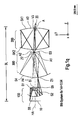
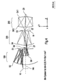
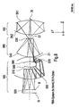
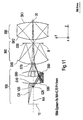
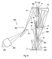
- FIG. 1a a microlithography projection exposure apparatus 2100 is shown.
- the microlithography projection exposure apparatus comprises a light source 2110, an illumination system 2120, a projection objective 2101 as well as a support structure or work surface 2130. Further, a Cartesian Coordinate system shown.
- the radiation of the light source 2110 is supplied to an illumination system 2120.
- the illumination system 2120 influences the radiation emanating from the light source 2110, for example, in which the radiation is homogenized or by directing a radiation beam 2122 of the radiation onto a mask 2140 which is positioned in an object plane 2103.
- the projection objective 2101 images the radiation reflected by the mask 2140 onto a substrate surface 2150 that is positioned in an image plane 2102.
- the pencil of rays on the image side of the projection objective 2101 is identified by reference numeral 2152.
- the substrate 2150 is supported by a support structure 2130, the support structure 2130 moving the substrate 2150 relative to the projection objective 2101 so that the projection objective 2101 images the mask 2140 onto different areas of the substrate 2150.
- the projection lens 2101 includes an optical axis 2105. As in FIG. 1a 2, the projection objective 2101 forms part of the mask 2140, which does not encompass the optical axis of the projection objective 2101, into an image plane 2102. In alternative embodiments, not shown, objects that lie on the optical axis HA of the projection objective can also be imaged into the image plane 2102.
- the light source 2110 is selected to provide electromagnetic radiation at an operating wavelength ⁇ at which the microlithography projection exposure apparatus 2100 is operated.
- the light source 2110 is a laser light source such as a laser plasma source for emission of EUV radiation or a KrF laser for wavelengths at 248 nm or an ArF laser at 193 nm.
- light sources other than laser light sources may be used are, such as light emitting diodes (LED) emit the radiation in the blue or UV range of the electromagnetic spectrum, for example. At 365 nm, 280 nm or 227 nm.
- the operating wavelength ⁇ of the microlithography projection exposure apparatus is in the ultraviolet or extreme ultraviolet (EUV) region of the electromagnetic spectrum.
- the operating wavelength can be 400 nm or less, 300 nm or less, in particular 200 nm or less, very particularly 100 nm or less.
- the operating wavelength can be in the range of 193 nm, preferably in the range of 157 nm, very particularly preferably in the EUV wavelength range, in particular in the region of 13 nm.
- the illumination system 2120 includes optical components that provide a collimated beam having a substantially homogeneous intensity profile.
- the lighting system 2120 further includes optics to direct the beam tuft 2122 onto the mask 2140.
- the illumination system 2120 further includes components that provide a particular polarization profile of the beam.
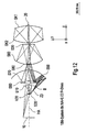
- the image plane 2103 has a distance L to the object plane 2102, which is also referred to as the overall length BL of the projection objective 2101. In general, this length depends on the specific configuration of the projection objective 2101 and the wavelength at which the microlithography projection exposure apparatus 2100 is operated. In the described embodiments, the overall length is in the range of one meter to about three meters, preferably in the range of about 1.5 m to 2.5 m.
- the overall length is less than 2 m, for example less than 1.9 m, preferably less than 1.8 m, very preferably less than 1.7 m, more preferably less than 1.6 m, particularly preferably less than 1.5 m.
- the projection lens 2101 has an imaging factor related to the ratio of the dimensions of the field in the object plane 2103 to the corresponding dimensions of the imaged field in the image plane 2102.
- the projection lenses used in lithography equipment are reduction projection lenses, i. that the dimensions of the image are smaller than those of the object.
- the projection lens 2101 may generate a field in the image plane 2102 whose dimensions are a factor of 2x or more, preferably 3x or more, more preferably 4x or more, most preferably 5x or more, particularly preferably 6x or more, preferably 7x or more preferably 8x or more, more preferably 9x or more, most preferably 10x or more, compared with the dimensions in the object plane 2103.
- projection lenses may also be developed that have an enlarged image or image of the same size as the object provide.
- FIG. 1b are the marginal rays 2152 of the light tufts that represent the objects in the image plane 2102 shown.
- the marginal rays 2152 define a beam cone.
- the angle of the beam cone is related to the image-side numerical aperture (NA) of the projection lens 2101.
- n 0 refers to the refractive index of the medium adjacent to the substrate 2150.
- This medium can, for example. Air, nitrogen, water or Be a vacuum.
- ⁇ max is the angle defined by the marginal rays of the projection lens 2101.
- projection objectives 2101 have a relatively high image-side numerical aperture NA.
- the image-side numerical aperture NA of the projection objective 2101 is more than 0.4, in particular more than 0.45, in particular more than 0.5, in particular more than 0.55, in particular more than 0.6, in particular more than 0 , 65, in particular more than 0.7, in particular more than 0.75, in particular more than 0.8, in particular more than 0.85, in particular more than 0.9.
- the resolution of the projection lens 2101 varies depending on the wavelength ⁇ and the image-side numerical aperture NA.
- R denotes the minimum dimension of the projection objective that can be resolved
- k is a dimensionless constant and is called a process factor.
- the process factor k varies depending on various factors, for example the polarization properties of the resist material. Typically, k ranges from 0.4 to 0.8, but k may also be below 0.4 and greater than 0.8, for specific applications.
- the projection objective 2101 has a relatively high resolution, ie, the value of R is relatively small.
- R may have a value of 150 nm or less, preferably 130 nm or less, most preferably 100 nm or less, more preferably 75 nm or less, most preferably 50 nm or less, preferably 40 nm or less, particularly preferably 35 nm or less, more preferably 32 nm or less, in particular 30 nm or less, preferably 28 nm or less, in particular 25 nm or less, particularly preferably 22 nm or less, preferably 20 nm or less, particularly preferably 18 nm or less, in particular 17 nm or less, very preferably 16 nm or less , in particular 15 nm or less, particularly preferably 14 nm or less, very preferably 13 nm or less, in particular 12 nm or less, preferably 11 nm or less, particularly preferably 10 nm or less.
- the quality of an image formed by the projection lens 2001 can be quantified in various ways.
- images may be characterized or quantified based on the measured or calculated deviations of the image from ideal conditions that can be achieved with Gaussian optics. These deviations are generally known as aberrations.
- One measure used to quantify the deviation of a wavefront from the ideal or desired shape is the root-mean-square wavefront error, the so-called RMS value W RMS .
- W RMS is, for example, as in " Handbook of Optics, Vol. 1, 2nd, edited by Michael Bass (McGraw Hill), Inc. 1995 on page 35.3 Are defined.
- the lower the W RMS value for a lens the less the wavefront deviates from the desired or ideal shape, and hence the better the quality of the image.
- the projection lens 2101 has very small values for W RMS of the image in the image plane 2102.
- a projection lens 2101 may have a W RMS value of about 0.1 ⁇ or less, more preferably less than 0.07 ⁇ , more preferably less than 0.06 ⁇ , more preferably less than 0.05 ⁇ , preferably less than 0.045 ⁇ ⁇ , in particular less than 0.04 ⁇ ⁇ , most preferably less than 0.035 ⁇ ⁇ , particularly preferably less than 0.03 ⁇ ⁇ , particularly preferably less than 0.025 ⁇ ⁇ , particularly preferably less than 0.02 ⁇ ⁇ , in particular preferably less than 0.15 ⁇ ⁇ , more preferably less than 0.01 ⁇ ⁇ have.
- the field curvature is defined as the peak-to-valley value of the axial focal plane position as a function of the field point.
- the projection lens 2101 has a relatively small field curvature for images in the image plane 2102. For example.
- the projection objective 2101 has an image-side field curvature of less than 20 nm, preferably less than 15 nm, more preferably less than 12 nm, more preferably less than 10 nm, most preferably less than 9 nm, preferably less than 8 nm, preferably less than 7 nm, more preferably less than 6 nm, more preferably less than 5 nm, most preferably less than 4 nm, more preferably less than 3 nm, preferably less than 2 nm, most preferably less than 1 nm.
- the distortion is defined as the maximum absolute value of the field-point-dependent storage of the pixel from the ideal pixel position in the image plane.
- the projection objective has a relatively small distortion of 10 nm or less, preferably 9 nm or less, more preferably 8 nm or less, particularly preferably 7 nm or less, most preferably 6 nm or less, particularly preferably 5 nm or less, in particular 4 nm or less, preferably 3 nm or less, very preferably 2 nm, preferably 1 nm or less.
- the projection objective 2101 comprises a plurality of mirrors arranged such that the radiation passing from a mask 2140 to a substrate 2150 is reflected such that an image of the mask 2140 on the surface of the substrate 2150 is formed.
- a projection lens Specific embodiments of a projection lens are as described in the following description educated. Generally speaking, the number, size and structure of the mirrors are determined by the desired optical properties of the projection objective 2101 and the physical constraints of the projection exposure apparatus 2100.
- the number of mirrors in the projection lens 2101 may vary. Typically, the number of mirrors is linked to different requirements for the optical properties of the objective.
- the projection lens 2101 has at least four mirrors, preferably at least five mirrors, more preferably at least six mirrors, more preferably at least seven mirrors, most preferably at least eight mirrors, preferably at least nine mirrors, more preferably at least ten mirrors, most preferably at least eleven mirrors, more preferably at least twelve mirrors.
- the projection objective 2101 in which mirrors of the objective are arranged between the object plane and the image plane, has an even number of mirrors, for example four mirrors, six mirrors, eight mirrors or even ten mirrors.
- the projection objective 2101 generally includes one or more mirrors with positive optical power. In other words, this means that the reflecting portion of the mirror, ie the effective area of the mirror, has a concave surface and is accordingly called a concave mirror or concave mirror.
- the projection objective 2101 may comprise two or more, for example, three or more, in particular four or more, very particularly five or more, in particular six or more concave mirrors.
- the projection lens 2101 may also include one or more mirrors having negative optical power. This means that one or more of the mirrors have a reflective section, ie a useful area with a convex surface. Such mirrors are also referred to as convex mirrors or convex mirrors.
- the projection lens 2101 have two or more, in particular three or more, especially four or more, in particular five or more, especially six or more convex mirror.
- the mirrors are arranged in projection lenses 2101 such that the radiation emanating from the object plane 2103 forms one or more intermediate images.
- Embodiments of the invention have one or more intermediate images and comprise two or more pupil planes.
- an aperture stop is arranged physically accessible at least in one of these pupil planes.
- the mirrors are configured such that a large portion of the light substantially reflects the operating wavelength ⁇ of the projection lens that impinges on the mirror surface at an angle or angular range.
- the mirrors can be designed such that they have, for example, more than 50%, preferably more than 60%, very preferably more than 70%, particularly preferably more than 80%, very particularly preferably more than 90% of the radiation incident on the surface a wavelength ⁇ are reflected.
- the mirrors comprise a multi-layer stack, called a multilayer stack, of layers of different material, the stack being configured to substantially reflect incident radiation of wavelength ⁇ on the surface.
- the multiple-layer stacks may comprise 20 or more, preferably 30 or more, more preferably 40 or more, most preferably 50 or more layers.
- the material chosen to form the multi-layer stacks is selected from the materials suitable for the operating wavelength ⁇ of the microlithography equipment.
- the multiple-layer system consists of alternating multiple layers consisting of molybdenum and silicon or molybdenum and beryllium to form mirrors that reflect radiation in the wavelength range of 10 nm to 30 nm, for example at a wavelength ⁇ of 13 nm or 11 nm.
- the mirrors are made of quartz glass coated with a single layer of aluminum. This in turn is overcoated, that is, overcoated with dielectric layers comprising materials such as MgF 2 , LaF 2 , Al 2 O 3 , for example for wavelengths of approximately 193 nm.
- the proportion of radiation reflected from a mirror varies as a function of the angle of incidence of the radiation on the mirror surface. Since the imaging radiation propagates through a catoptric projection lens along a variety of different paths, the angle of incidence of the radiation on each mirror can vary.
- Figure 1c shows part of a mirror 2300 in meridional section, that is, in the meridional plane.
- the meridional plane is a plane of the projection lens that includes the optical axis.
- the mirror 2300 includes a concave reflective mirror surface 2301.
- the imaging radiation impinging on the surface 2301 along different paths includes, for example, the paths represented by the beams 2310, 2320, 2330.
- the beams 2310, 2320, and 2330 are incident on a part of the mirror surface 2301.
- the normal to the surface of the mirror are different in this area of the mirror surface 2301.
- the direction of the surface normals in this area are represented by the straight lines 2311, 2321 and 2331, which are corresponding to the beams 2310, 2320 and 2330.
- the rays 2310, 2320, and 2330 strike the surface at the angles ⁇ 2310 , ⁇ 2320, and ⁇ 2330 .
- the angles of incidence of the imaging rays can be represented in a variety of ways.
- One possible representation is the maximum angle of the rays impinging on each mirror in the meridional section of the projection objective 2101. This maximum Angle is denoted by ⁇ max .
- the angle ⁇ max of different mirrors of the projection lens 2101 may vary.
- the maximum value ⁇ max (max) for all mirrors of the projection objective 2101 is 75 ° or less, preferably 70 ° or less, more preferably 65 ° or less, particularly preferably 60 ° or less, preferably 55 ° or less , in particular 50 ° or less, in particular 45 ° or less.
- the maximum angle ⁇ max (max) is relatively low.
- the maximum angle ⁇ max (max) may be 40 ° or less, preferably 35 ° or less, very preferably 30 ° or less, in particular 25 ° or less, particularly preferably 20 ° or less, in particular 15 ° or less, in particular 13 ° or less, more preferably 10 ° or less.
- ⁇ CR ⁇ CR .
- ⁇ CR ⁇ CR .
- a maximum angle ⁇ CR (max) in the projection lens can be defined as the maximum principal ray angle of the central field point.
- This angle ⁇ CR (max) can be relatively low, for example, the maximum angle ⁇ CR (max) in the projection lens is less than 35 °, preferably less than 30 °, very preferably less than 25 °, in particular less than 15 °, in particular less than 13 °, in particular preferably less than 10 °, preferably less than 8 ° or very preferably less than 5 °.
- Each mirror in the projection objective 2101 may further be characterized by a range of angles of incidence in the meridonal section of the projection objective 2101.
- the range in which the angle ⁇ varies on each mirror is referred to as ⁇ .
- ⁇ is defined by the difference between an angle ⁇ (max) and ⁇ (min) , where ⁇ (min) is the minimum angle of incidence of the imaging rays on a mirror surface in the meridional section of the projection objective 2101 and ⁇ (max) is the maximum value of the incident imaging rays on a mirror surface, as previously defined.
- the range ⁇ varies for each mirror in the projection lens 2101.
- ⁇ may be relatively small.
- ⁇ may be less than 10 °, preferably less than 8 °, particularly preferably less than 5 °, very preferably less than 3 °, in particular less than 2 °.
- ⁇ may be relatively large.
- ⁇ may be 20 ° or more, in particular 25 ° or more, particularly preferably 30 ° or more, particularly preferably 35 ° or more, very particularly 40 ° or more.
- the maximum value for ⁇ , the value ⁇ max, the maximum value of the angular variation on a mirror for all mirrors in the projection lens 2101 may be relatively low.
- the value ⁇ max may be less than 25 °, in particular less than 20 °, very particularly less than 15 °, in particular less than 12 °, in particular less than 10 °, in particular less than 8 °, in particular less than 7 ° less than 6 °, more preferably less than 5 °, most preferably less than 4 °.
- catoptric projection lenses are designed to take into account the obscuration of the light path caused by the reflective elements, as opposed to transmissive elements used in dioptric systems.
- FIG Figure 1d An example of a mirror 2600 comprising an opening for the passage of a jet tuft is in FIG Figure 1d shown.
- the mirror 2600 includes an aperture 2610.
- the mirror 2600 may be disposed in the projection lens 2101 such that the optical axis 2105 intersects the aperture 2610.
- the mirror 2600 is circular in shape with a diameter D. In general, D is determined by the design of the projection lens 2101.
- D is 1500 mm or less, preferably 1400 mm or less, more preferably 1300 mm or less, especially 1200 mm or less, very particularly 1100 mm or less, most preferably 1000 mm or less, particularly preferably 900 mm or less, very particularly preferably 800 mm or less, very preferably 700 mm or less, in particular 600 mm or less, preferably 500 mm or less, very particularly 400 mm or less, very preferably 300 mm or less, in particular 200 mm or less, very preferably 100 mm or less.
- the mirrors of the projection lens 2101 may include an aperture of circular or non-circular shape.
- Mirrors which are not of circular shape may have a maximum dimension which is less than 1500 mm, preferably less than 1400 mm, in particular less than 1300 mm, preferably less than 1200 mm, in particular less than 1100 mm, preferably less than 1000 mm , in particular less than 900 mm, preferably less than 800 mm, in particular less than 700 mm, preferably less than 600 mm, in particular less than 500 mm, preferably less than 400 mm, in particular less than 300 mm, preferably less than 200 mm, in particular less than 100 mm.
- the opening 2610 is, for example, circular with a diameter D 0 .
- D 0 depends on the design of the projection lens 2101 and is generally sized to provide a sufficiently large aperture for the passage of radiation from the object plane 2103 to the image plane 2102.
- the opening can also be non-circular.
- non-circular openings include polygonal openings such as a square opening, a rectangular opening, a hexagonal opening, an octagonal opening and non-circular arcuate openings, for example elliptical openings or irregular curved openings.
- Openings of non-circular shape may have a maximum diameter of 0.75D or less, more preferably 0.5D or less, preferably 0.4D or less, more preferably 0.3D or less, preferably 0.2D or less, especially 0.1 D or less, preferably 0.05 D or less.
- mirrors may include non-circular openings having a maximum dimension of about 50 mm or less, preferably 45 mm or less, more preferably 40 mm or less, preferably 35 mm or less, in particular 30 mm or less, preferably 25 mm or less , in particular 20 mm or less, preferably 15 mm or less, in particular 10 mm or less, in particular 5 mm or less.
- the apertures may be formed in different mirrors of the same shape or different shape. Furthermore, the openings for the passage of radiation in different mirrors may have the same dimension or different dimensions.
- FIG. 1 e An example of a mirror 2660 that does not include an opening is in FIG FIG. 1 e shown.
- the mirror 2660 has the shape of a ring segment.
- the mirror 2660 corresponds in shape to a segment of a circular mirror 2670 having a diameter D.
- the mirror 2660 has a maximum dimension in the x direction given by M x .
- M x may be 1500 mm or less, preferably 1400 mm or less, in particular 1300 mm or less, in particular 1200 mm or less, preferably 1100 mm or less, in particular 1000 mm or less, preferably 900 mm or less, in particular 800 mm or less, preferably 700 mm or less, in particular 600 mm or less, in particular 500 mm or less, preferably 400 mm or less, in particular 300 mm or less, preferably 200 mm or less, in particular 100 mm or less.
- the mirror 2660 is symmetric with respect to the meridian 2675.
- the mirror 2660 has a dimension M x along the meridian 2675.
- M y may be less than or greater than M x .
- M x is in the range of 0.1 M x , preferably 0.2 M x or more, in particular 0.3 M x or more, in particular 0.4 M x or more, preferably 0.5 M x or more, in particular 0, 6 M x or more, preferably 0.7 or more, in particular 0.8 M x or more, very preferably 0.9 M x or more.
- M y may be 1.1 M x or more, preferably 1.5 M x or more, or in the range of 2 M x 10 M x .
- M y may be about 1000 mm or less, preferably 900 mm or less, more preferably 800 mm or less, preferably 700 mm or less, more preferably 600 mm or less, preferably 500 mm or less, more preferably 400 mm or less, especially 300 mm or less , in particular 200 mm or less, preferably 100 mm or less.
- Mirrors that do not include an aperture may be arranged so that the optical axis 2105 intersects the mirror or else that the optical axis 2105 does not intersect the mirror.
- the projection lens 2100 can include mirrors of different shapes and sizes, depending on the design.
- the maximum dimension of each mirror of the projection lens may be 1500 mm or less, preferably 1400 mm or less, in particular 1300 mm or less, preferably 1200 mm or less, in particular 1100 mm or less, especially 1000 mm or less, in particular 900 mm or less, preferably 800 mm or less, in particular 700 mm or less.
- the projection lens 2101 includes a group of mirrors, for example, 2 or more mirrors, 3 or more mirrors, 4 or more mirrors, 5 or more mirrors, 6 or more mirrors that have no opening and that are arranged to be one Mapping object, for example, in an image plane 2102 or in an intermediate image plane.
- the projection objective 2101 comprises groups or groups of mirrors
- the group of mirrors is referred to as a partial objective or subsystem.
- the projection lens 2101 may include more than one sub-objective.
- the projection objective may comprise two partial objectives, three partial objectives, four partial objectives or more than four partial objectives.
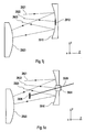
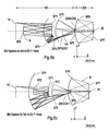
- An example of a partial lens is the partial lens 2400, which is shown in FIG. 1f is shown.
- the partial objective 2400 comprises mirrors 2410, 2420, 2430 and 2440 arranged in such a way as to image the radiation from an object plane 2403, which corresponds to the object plane 2103 or an intermediate image plane, into an image plane 2402 corresponding to the image plane 2102 or an intermediate image plane.
- the reflective surfaces of the mirrors 2410, 2420, 2430, and 2440 are portions of axially symmetric surfaces in which the remainder of the mirror surface has been removed to provide a path for the imaging radiation.
- the parts of the mirrors are the portions of the mirror surface to which radiation impinges. They are also referred to as useful areas.
- the first mirror in the path of the radiation which passes through the projection lens, ie in the beam path or light path, is present mirror 2420 which is closest to, ie in the vicinity of the plane 2402, while the second mirror in the light path, ie Beam path of the mirror 2410 is the closest to, that is, located near the plane 2403.
- the in Figure 1g The partial objective 2450, mirrors 2460, 2470, 2480 and 2490, which image light of an object plane 2453, which can correspond, for example, to the object plane 2103 or an intermediate image plane, into an image plane 2452, for example corresponding to the image plane 2102 or an intermediate image plane.
- the mirrors forming sub-objective 2400, ie mirrors 2460, 2470, 2480 and 2490, are portions of axially symmetric surfaces in which the remainder of the mirror surface would be removed to provide an optical path for the imaging beam path (s), ie In the present case, only the areas of the mirrors are shown that reflect light, the so-called. Nutz Schemee.
- the third mirror in the beam path, the mirror 2480 is closest to the plane 2452, whereas the second mirror in the beam path or the light path of the mirror 2460 is closest to the plane 2403.
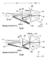
- a partial objective may also be formed from mirrors that include an aperture.
- a partial objective 2500 is shown, which consists of mirrors 2510, 2520, in which the mirror 2510 has an opening 2511.
- the partial objective 2500 is constructed in such a way that it images rays into an image plane 2502, which may correspond, for example, to the image plane 2102 or an intermediate image plane.
- partial objective 2550 Another example of a sub-objective constructed on mirrors comprising an aperture is shown.
- This partial objective is referred to as partial objective 2550.
- the partial objective 2550 comprises mirrors 2560 and 2570.
- the mirror 2560 comprises an opening 2561 and mirror 2570 comprises an opening 2571.
- the partial objective 2550 is designed such that it images radiation or light into an image plane 2552, the image plane forming the image plane Image plane 2102 or an intermediate image plane corresponds.
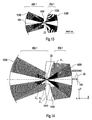
- Partial lenses that use mirrors that have an aperture cause part of the pupil of the partial objective to obscure. Accordingly, embodiments of a projection lens 2101 having such a partial objective have an obscured pupil.
- the extent to which the pupil of the projection objective 2101 is obscured can be characterized by the value R obs , which indicates the proportion of the aperture radius of the projection objective 2101 that is obscured in the pupil plane in a meridional section or in the meridional plane of the projection objective 2101. Due to the rotational symmetry of the system with respect to the optical axis, it is sufficient to calculate the obscuration radius in the meridional plane.
- the projection objective 2100 may have a very low pupil obscuration.
- R obs may be 30% or less, preferably 25% or less, more preferably 22% or less, preferably 20% or less, more preferably 18% or less, preferably 15% or less, more preferably 12% or less preferably 10% or less of Aperturradius amount.
- the projection lens 2101 includes one or more pupil planes that are physically accessible to.
- Light obscuring element z. B. to arrange a shading diaphragm substantially in the pupil plane, wherein the pupil plane intersects the optical axis 2105.
- An arrangement of an obscuration diaphragm or a shading diaphragm in a pupil position can lead to a field-independent obscuration of the pupil.
- the shading diaphragms are preferably formed of a material or consist of a coating which does not reflect radiation at the operating wavelength ⁇ , ie the material substantially absorbs incident radiation of the operating wavelength ⁇ .
- the shading diaphragm is designed such that no scattered radiation enters the system.
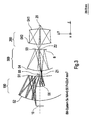
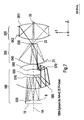
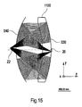
- a mirror 2910 is shown which is disposed substantially in a pupil plane of the projection lens 2101 and has an obscuration aperture 2912 on the mirror surface.
- the obscuration diaphragm 2912 can, for example, consist of a non-reflective coating for radiation at a wavelength ⁇ .
- the obscuration stop 2912 blocks radiation propagating along certain beam paths. This is in Fig. 1j illustrated by rays 2921, 2922 and 2923.
- Rays 2921 and 2923 intersect the reflective portion of mirror 2910, whereas beam 2922 intersects shading panel 2912. Accordingly, the mirror 2910 reflects radiation propagating along the path 2921 and 2923 to a downstream mirror 2920. On the other hand, the radiation propagated along the beam path 2922 is blocked by the obscuration shutter 2912.
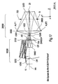
- the obscuration stop may be disposed between the mirrors in the projection lens 2101.
- an obscuration stop may be placed in a pupil plane that does not coincide with planes of other mirrors arranged in the projection objective.
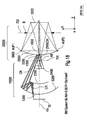
- a shadow stop 2926 is placed between mirrors 2910 and 2920 to block radiation propagating along certain beam paths between the mirrors.
- the obscuration orifice may be placed with the aid of an auxiliary beam 2928 that passes through an opening 2924 of the mirror.
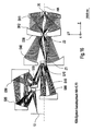
- an obscuration stop 2930 is placed between the mirrors 2910 and 2920 with the obscuration stop being held by a retainer ring 2932 whose inner diameter is larger than the aperture of the projection objective in the pupil plane in which the obscuration stop 2930 is located.
- the obscuration shutter 2930 is held on an annular frame member 2932 by means of radial suspensions 2934.
- the suspensions 2934 are designed to block non-significant radiation or light.
- a shading stop which is arranged substantially in a pupil plane, can be removed or exchanged with another shading stop without having to exchange a mirror of the projection objective.
- the obscuration apertures may be disposed on transmissive optical elements.
- transmissive optical elements For example, at operating wavelengths where materials exist that are sufficiently transmissive and have sufficient mechanical strength, an obscuration stop can be held on a transmissive flat element.
- the shading apertures can be realized by coating or placing an obscuration stop on a flat glass element of sufficient size that the flat glass segments are held by the body of the objective 2101.
- Obscuration apertures can be used in embodiments in which at least one mirror of the projection objective 2101 has an opening for the passage of radiation.
- the size of the obscuration apertures may vary.
- the obscuration stop is selected to have the smallest possible size that must be provided to provide substantially field independent obscuration of the exit pupil of the projection objective.
- the obscuration shutter may have a radial dimension of about 60% or less, more preferably 55% or less, more preferably 50% or less, more preferably 45% or less, most preferably 40% or less, in particular 35% or less, in particular 30% or less, in particular 25% or less, especially 20% or less of the radius of the pupil aperture.
- the shape of the field of the projection lens 2101 may vary.
- the field may have an arcuate shape, for example, the shape of a segment of a ring, a so-called ring field.
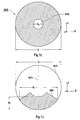
- a projection lens may have the partial lenses formed of mirrors without an aperture, as the partial lenses 2400 and 2450 described above, a field in the form of a ring field, In FIG. 1f a ring segment 2700 or ring field is shown.
- This ring segment 2700 can be characterized by an x-dimension D x , a y-dimension D y and a radial dimension D r .
- D x and D y correspond to the dimension of the field or to the dimension of the field along the x-direction and the y-direction. These quantities are given in the description below.
- D r corresponds to the ring radius measured from the optical axis 2105 to the inner boundary of the field 2700.
- the ring field segment 2700 is symmetrical with respect to the plane parallel to the yz plane, as indicated by the line 2710.
- the size of D x , D y and D r is variable and depends on the design of the projection lens 2101.
- D x is greater than D y .
- the relative size of the field dimensions D x , D y and D r in the object plane 2103 and the image plane 2102 vary depending on the magnification or reduction of the projection lens 2101. In some embodiments, D x in the image plane 2103 is relatively large.
- D x in the image plane 2101 may be greater than 1 mm, preferably greater than 3 mm, in particular greater than 4 mm, preferably greater than 5 mm, in particular greater than 6 mm, in particular greater than 7 mm, preferably greater than 8 mm, in particular greater than 9 mm, preferably greater than 10 mm, in particular greater than 11 mm, preferably greater than 12 mm, in particular greater than 13 mm, preferably greater than 14 mm, in particular greater than 15 mm, preferably greater than 18 mm, in particular greater than 20 mm, preferably larger than 25 mm.
- D y in the image plane 2102 can be in the range of 0.5 mm to 5 mm, for example up to 1 mm, preferably up to 2 mm, in particular up to 3 mm, very particularly preferably up to 4 mm.
- D r in the image plane 2102 is in the range of 10 mm to 50 mm.
- D r may be, for example, 15 mm or more, for example 20 mm or more, in particular 25 mm or more, preferably 30 mm or more in the image plane 2102.
- the central field point 2705 for the ring field 2700 is shown.
- the projection objective 2101 can have a maximum field dimension or field dimension of more than 1 mm, in particular more than 3 mm, preferably more than 4 mm, in particular more than 5 mm, preferably more than 6 mm, in particular more than 7 mm. preferably more than 8 mm, in particular more than 9 mm, preferably more than 10 mm, in particular more than 11 mm, preferably more than 12 mm, in particular more than 13 mm, preferably more than 14 mm, in particular more than 15 mm, preferably more than 18 mm, in particular more than 20 mm or more than 25 mm in the image plane 2102 amount.
- the embodiment of the projection lens 2101 has a relatively large image-side free working distance.
- the image-side free working distance refers to the shortest distance between the image plane 2102 and the mirror surface of the mirror, which is arranged geometrically closest to the image plane 2102. This is in Figure 1o showing a mirror 2810 geometrically located closest to the image plane 2102. The radiation is reflected by the surface 2811 onto the mirror 2810.
- the image-side free working distance is denoted by D w .
- D w is 25 mm or more, preferably 30 mm or more, in particular 35 mm or more, preferably 40 mm or more, in particular 45 mm or more, preferably 50 mm or more, in particular 55 mm or more, preferably 60 mm or more, especially 65 mm or more.
- a relatively large working distance is desirable because it allows the surface of the substrate 2150 to be in the Image plane 2102 can be arranged without the one side of the mirror 2810, which is indicative of the image plane 2102, is touched.
- the object-side free working distance refers to the shortest of the distance between the object plane 2103 and the plane of the reflective side of the mirror in the projection lens 2101, which is geometrically located closest to the object plane 2103.
- the projection lens 2101 has a large object-side free working distance.
- the projection lens 2101 may have an object-side free working distance of 50 mm or more, preferably 100 mm or more, more preferably 150 mm or more, preferably 200 mm or more, more preferably 250 mm or more, preferably 300 mm or more, especially 350 mm or more , in particular 400 mm or more, preferably 450 mm or more, preferably 500 mm or more, in particular 550 mm or more, preferably 600 mm or more, in particular 650 mm or more, preferably 700 mm or more, preferably 750 mm or more, in particular 800 mm or more, preferably 850 mm or, in particular 900 mm or more, in particular 950 mm or more, in particular 1000 mm or more.
- a relatively large object-side free working distance may be advantageous in embodiments in which the space between the projection objective 2101 and the object plane 2103 must be accessible.
- the mask 2140 is reflective, it is necessary to illuminate the mask from the side facing the objective 2101. Therefore, there should be enough space between the projection lens 2101 and the object plane 2103 to illuminate the mask by the illumination system 2120 at a certain illumination angle.
- a large object-side free working distance allows flexibility in the design of the remainder of the microlithography projection objective, for example, by providing sufficient space for attaching other components of the projection objective 2101 and the support structure for the mask 2140.
- the mirror that is closest to the object plane 2103 is positioned to be a long distance from the optical axis 2105. In other words, this means that the optical axis 2105 does not intersect the mirrors that are closest to the object plane 2103.
- FIG. 1p shown. This in FIG. 1p The system shown comprises four mirrors 2941 to 2944, with mirror 2941 located closest to the object plane 2103. The minimum distance between the mirror 2941 and the optical axis 2105 is the distance 2946.
- the distance 2946 may be 50 mm or more, preferably 60 mm or more, in particular 70 mm or more, very particularly 80 mm or more, in particular 90 mm or more, very particularly 100 mm or more, in particular 110 mm or more, especially 120 mm or more, in particular 130 mm or more, very particularly 140 mm or more, in particular 150 mm or more, in particular 160 mm or more, in particular 170 mm or more, in particular 180 mm or more, in particular 190 mm or more, in particular 200 mm or more, in particular 210 mm or more, in particular 220 mm or more, in particular 230 mm or more, in particular 240 mm or more, in particular 250 mm or more, in particular 260 mm or more, in particular 270 mm or more, in particular 280 mm or more, especially 290 mm or more, more preferably 300 mm or more.
- the distance to the optical axis 2946 is relatively large, as this provides a very large space near the location where the optical axis 2105 intersects the object plane 2103.
- This space can be used to arrange other components of the exposure system or of the lithographic tool, such as, for example, one or more optical components of the illumination system, for example a gracing-incidence mirror, a so-called reflective gracing-incidence element.
- Some of the radiations projected by the projection lens follow light path 2947.
- the rays intersect the mirrors in the following order: mirrors 2942, mirror 2941, mirror 2943 and mirror 2944.
- the light path 2947 intersects with itself in the meridional plane between the mirrors 2941 and 2943 before being reflected at the mirror 2942.
- the projection lens 2101 is configured so that principal rays from the reticle 2140 either converge to or diverge from or parallel to the optical axis 2105.
- the position of the entrance pupil of the projection objective 2101 with respect to the object plane 2103 may vary depending on the Design of the projection lens.
- the object plane 2103 lies between the projection lens 2101 and the entrance pupil of the projection objective 2101.
- the entrance pupil may be positioned between the object plane 2103 and the projection objective 2101.
- the illumination system 2120 may be arranged such that the exit pupil of the illumination system is arranged substantially at the location of the entrance pupil of the projection objective 2101.
- the illumination system 2120 includes a telescope system that projects the exit pupil of the illumination system to the location of the entrance pupil of the projection objective 2101.
- the exit pupil of the illumination system 2120 is placed in the area of the entrance pupil of the projection objective 2101, without a telescope system being present in the illumination system. For example.
- the exit pupil of the illumination system 2120 coincides with the entrance pupil of the projection objective without having to use a telescope system in the illumination system.
- the projection lens 2101 can be designed using commercially available optical design programs such as ZEMAX, OSLO, Code V. Starting with the definition of the wavelength, the field size and the numerical aperture, the optical properties can be optimized are required for a projection lens, such as the wavefront error, the telecentricity, the uniformity and the distortion.
- optical design programs such as ZEMAX, OSLO, Code V.
- the image scale is sixfold, ie the image is 6 times smaller in the image plane than the object and the resolution is 15 nm.
- the image-side W RMS 0.024 ⁇ and the image field curvature, ie the field curvature 3 nm.
- the overall length of the system is 1745 mm.
- the projection objective according to the invention comprises three partial objectives, the first partial objective 100, the second partial objective 200 and the third partial objective 300.
- the first partial objective comprises a total of four mirrors, S1, S2, S5 and S6. Seen in the light path from the object plane 10 to the image plane 20, the mirror S1 is a concave mirror, the mirror S2 is a convex mirror, the seventh mirror S5 is a convex mirror, and the mirror S6 is a concave mirror.
- the imaging factor of the first partial objective is 1.77x.
- An aperture stop B is arranged on the mirror S5.
- the object plane in which, for example, the reticle comes to rest is denoted by 10.
- the optical axis about which the individual mirror segments are rotationally symmetric is designated HA and the total length of the system from the object plane 10 to the image plane 20, which is also referred to as the overall length, is BL.
- the first partial objective is also referred to as a field group and comprises at least two mirrors, the mirror S1 and the mirror S2.
- Mirror S1 and mirror S2 are like Fig. 1 shows off-axis mirror segments so-called off-axis mirror segments that allow the correction of field-dependent aberrations.
- the first partial objective 100 is followed by a transfer group, referred to herein as the third partial objective 300, comprising two mirrors, the mirror S3 and the mirror S4, where S3 is a convex mirror and S4 is a concave mirror.
- an intermediate image Z1 is formed in or near the concave mirror S4, and an intermediate image Z2 of the projection objective is physically formed in the vicinity of the convex mirror S3.
- the imaging factor of the third partial objective which is also referred to as a transfer group, is 2.88x.
- the third partial objective is followed by a so-called relay group, which is also referred to as the second partial objective 200 and has an imaging factor of 1.18x.
- the second partial objective 200 in the present case comprises two mirrors, which are both designed as concave mirrors. These mirrors are therefore also referred to as primary concave mirror SK1 and secondary concave mirror SK2.
- the mirror S3 includes an aperture opening A1
- the secondary concave mirror SK2 includes an aperture opening A2, the primary concave mirror an aperture aperture A3, and the mirror S4 an aperture aperture A4.
- the mirror S3, S4 SK1 and SK2 mirror with an opening through which a beam tuft passes in the sense of the application.
- the mirror S3, S4, SK1, SK2 in the context of this application from a second sub-objective, which has only mirror with an opening for the passage of a beam tuft.
- the resulting radius providing the field-independent obscuration is 43% of the aperture radius.
- the mirrors S1, S2, S5 and S6 form a first sub-objective which does not have a mirror with an opening for the passage of a beam tuft, ie no pierced mirror.
- the object-side free working distance is 100 mm.
- the second partial objective 200 images the second intermediate image Z 2 into the image plane 20.
- the third partial objective connects the lower-aperture objective part to the high-aperture objective part.
- the third partial objective is therefore also called a transfer group.
- the maximum angle of incidence ⁇ CR (max) of the main beam to the central field point is auf max (max) 33.8 ° on the mirrors S1, S2, S3, S4, S5, S6, SK1, SK2.
- the maximum angle of incidence of each beam on the mirrors S1, S2, S3, S4, S5, S6, SK1 and SK2 is 38.6 °.
- the maximum angle range ⁇ max of the incident rays on each mirror S1, S2, S3, S4, S5, S6, SK1 and SK2 is 12 °.
- the size of the largest mirror in the meridional section, ie in the meridional plane is 669 mm.
- the size of the largest mirror in the x-direction is 675 mm.
- optical data of the system according to Figure 1q can be taken from the following Table 1.
- the first part of Table 1 represents the optical data and the second part of Table 1 represents the aspheric constants of the respective mirror surfaces.
- Table 1 ⁇ / u> Surface radius Thickness Fashion Object INFINITY 316480 Mirror 1 -375233 -77,505 REFL Mirror 2 2976.73 51007 REFL STOP INFINITY 0000 Mirror 3 127889 -189982 REFL Mirror 4 329839 1029.934 REFL Mirror 5 787.6 -596052 REFL Mirror 6 735437 1171.383 REFL Mirror 7 -1195.158 -512255 REFL Mirror 8 977668 552254 REFL image INFINITY 0000 Surface K A B C Mirror 1 0.00000E + 00 -3.72335E-09 -1.17134E-13 -9.45919E-19 Mirror 2 0.00000E + 00 -6.42297E-08 5.78359E-13 -1.12102E-17 Mirror 3 0.00000E + 00 -1.89730E-07 1.46577E
- the operating wavelength 1 is 13.5 nm.
- the resolution of the lens is 17 nm and the overall length is 1711 mm.
- the image side W RMS is 0.044 ⁇ and the image side field curvature is 12 nm.
- the obscuration radius, which provides field independent obscuration, is 36% of the aperture radius.
- the image-side free working distance is 69 mm and the object-side free working distance 100 mm.
- the maximum angle of incidence ⁇ CR (max) of the main beam to the central field point on the mirrors S1, S2, S3, S4, S5, S6, SK1 and SK2 is 19.4 °.
- the maximum angle of incidence ⁇ max (max) of any beam on the mirrors S1, S2, S3, S4, S5, S6, SK1 and SK2 is 21.8 °.
- the maximum angle range ⁇ max of the incident rays on each mirror S1, S2, S3, S4, S5, S6, SK1 and SK2 is 15 °.
- the largest mirror has a dimension in the meridional section of 385 mm and the size of the largest mirror in the x-direction is 616 mm.
- the first part of Table 2 represents the optical data and the second part of Table 2 represents the aspherical constants of the respective mirror surfaces.
- Table 2 ⁇ / u> Surface radius Thickness Fashion Object INFINITY 762134 Mirror 1 44367.928 -662134 REFL Mirror 2 1027.348 717444 REFL Mirror 3 122696 -209209 REFL Mirror 4 298792 645481 REFL STOP INFINITY 0000 Mirror 5 1184.237 -391582 REFL Mirror 6 518111 780329 REFL Mirror 7 -834844 -288328 REFL Mirror 8 612533 357344 REFL image INFINITY 0000 Surface K
- a B 1 0.00000E + 00 -7.47500E-11 -1.75668E-16 Mirror 2 0.00000E + 00 -1.89057E-11 -2.80932E-17 Mirror 3 0.00000E + 00 4.36794E-08 -1.06646E-11 Mirror 4 0.00000E + 00 2.82491E-10 8.34214E
- the size of the field which is determined by the lens FIG. 2 is 13 x 1 mm 2 in the image plane.
- the aperture stop B at the in FIG. 2 shown embodiment on the convex mirror of the transfer group - this is the mirror S3 - arranged.
- the partial objective 100 comprises the mirrors S1, S2, S5 and S6 and forms an intermediate image Z1 in or near the mirror S4.
- the second partial objective 200 comprises the mirrors SK1 and SK2 and the third partial objective 300 comprises the mirrors S3 and S4.
- the third partial lens forms an intermediate image Z2 in or near the mirror S3.
- FIG. 3 is a similar 8-mirror system as in FIG. 2
- the magnification or the imaging factor in the exemplary embodiment is shown in FIG. 3 5x ie the image is reduced 5-fold compared to the object.
- the resolution of the system is 17 nm, the length of the system 1509 mm.
- the image-side W RMS is 0.01 ⁇ and the image-side field curvature is 2 nm.
- the image-side free working distance is 69 mm and the object-side free working distance 104 mm.
- the maximum angle of incidence ⁇ CR (max) to the mirrors S1, S2, S3, S4, S5, S6, SK1 and SK2 of the main beam to the central field point is 23.1 °.
- the maximum angle of incidence ⁇ max (max) of each beam to a mirror S1, S2, S3, S4, S5, S6, SK1 and SK2 is 26.6 °.
- the maximum incidence range ⁇ max on any mirror S1, S2, S3, S4, S5, S6, SK1 and SK2 is 16 °.
- the size of the largest mirror in the meridional section is 394 mm and the size of the largest mirror in the x-direction is 669 mm.
- the obscuration radius which provides field independent obscuration, is 35% of the aperture radius.
- the mirrors S3, S4, SK1 and SK2 include openings. The mirrors are designed so that three partial lenses are formed.
- the first partial objective comprises the mirrors S1, S2, S5 and S6 and forms an intermediate image Z1 in or near the mirror S5.
- the second partial objective 300 comprises two mirrors SK1 and SK2.
- the third partial objective comprises two mirrors S3 and S4.
- the diaphragm is formed on the third mirror S3.
- the first part of Table 3 represents the optical data and the second part of Table 3 represents the aspheric constants of the respective mirror surfaces.
- Table 3 ⁇ / u> Surface radius Thickness Fashion Object INFINITY 546051 Mirror 1 1813.761 -442075 REFL Mirror 2 659925 484056 REFL Mirror 3 124229 -230251 REFL Mirror 4 297991 681239 REFL STOP INFINITY 0000 Mirror 5 1044.821 -388855 REFL Mirror 6 513480 790082 REFL Mirror 7 -788712 -300808 REFL Mirror 8 679931 369811 REFL image INFINITY 0000 Surface K A B Mirror 1 0.00000E + 00 -1.19695E-10 -8.52500E-16 Mirror 2 0.00000E + 00 -3.36861 E-12 -7.92767E-18 Mirror 3 0.00000E + 00 9.84422E-08 1.34188E-11 Mirror 4 0.00000E + 00 1.55138E-09 3.79123E-14 Mirror 5
- FIG. 1 and 2 Same components as in FIG. 1 and 2 are in FIG. 3 with the same reference numerals.
- the mirrors S3, S4, SK1 and SK2 include openings.
- the mirrors S1, S2, S5 and S6 do not include openings.
- the first partial objective 100 comprises the mirrors S1, S2, S5 and S6.
- the first partial objective forms an intermediate image Z1 in the vicinity of the mirror S5.
- the second partial objective 200 comprises the mirrors SK1, SK2 and the third partial objective comprises the mirrors S3 and S4.
- the third partial objective 300 forms an intermediate image Z2.
- the system has three pupil levels and two intermediate images. At least one of the pupil planes is accessible to the placement of an aperture stop.
- the first part of Table 4 represents the optical data and the second part of Table 4 represents the aspherical constants of the respective mirror surfaces.
- Table 4 ⁇ / u> Surface radius Thickness Fashion Object INFINITY 541176 Mirror 1 1654.286 -438932 REFL Mirror 2 662227 486164 REFL Mirror 3 124521 -234334 REFL Mirror 4 296656 684148 REFL STOP INFINITY 0000 Mirror 5 1078.372 -388948 REFL Mirror 6 513362 789957 REFL Mirror 7 -788995 -300590 REFL Mirror 8 680459 369601 REFL image INFINITY 0000 Surface K A B Mirror 1 0.00000E + 00 -2.36631 E-10 -8.55660E-16 Mirror 2 0.00000E + 00 -5.67713E-12 -1.95884E-17 Mirror 3 0.00000E + 00 1.11517E-07 1.37540E-11 Mirror 4 0.00000E + 00 1.49061E-09 3.64316E
- the aperture diaphragm B is arranged on the mirror S3 in the transfer group.
- the size of the field is according to the embodiment FIG. 4 18 ⁇ 1 mm 2 .
- the resolution of the system is 17 nm, the overall length is 2000 mm.
- the image-side W RMS is 0.033 ⁇ and the image-side field curvature 7nm.
- the image-side free working distance is 61 mm and the object-side free working distance 100 mm.
- the maximum angle of incidence ⁇ CR (max) to a mirror S1, S2, S3, S4, S5, S6, SK1 and SK2 of the main beam to the central field point is 15.9 °.
- the maximum angle of incidence ⁇ max (max) of each beam on the mirrors S1, S2, S3, S4, S5, S6, SK1 and SK2 is 17.9 °.
- the maximum range ⁇ max of the angles of incidence on each mirror S1, S2, S3, S4, S5, S6, SK1 and SK2 is 10.6 °.
- the size of the largest mirror in the meridional section, ie in the meridional plane is 574 mm and the size of the largest mirror in the x-direction is 602 mm.
- the system shown is the first partial objective 100, the so-called. Field group comprising the mirror S1, S2, S5 and S6 constructed substantially the same, as in the embodiments according to FIG. 2 . 3 and 4 ,
- the mirrors S1, S2, S5 and S6 have the following mirror sequence: convex-concave-convex-concave, ie the first mirror S1 in the light path from the object plane to the image plane has a convex mirror surface, the second mirror in the light path from the image plane to the object plane, the mirror S2 - has a concave mirror surface, the third mirror in the light path from the object plane 10 to the image plane 20 - the mirror S5 - has a convex mirror surface and the fourth mirror in the light path from the object plane 10 to the image plane 20 - the mirror S6 - has a concave mirror surface.
- the second partial objective 200 comprises the mirrors SK1 and SK2 and the third partial objective, the so-called transfer group, the mirrors S3 and S4.
- the mirrors S3, S4, SK1 and SK2 include openings, and the mirrors S1, S2, S5 and S6 do not include openings.
- the radius of the first mirror in the light path from the object plane to the image plane ie, the radius of the mirror S1 is very large, eg. In the embodiment according to FIG. 5 greater than 10 m.
- the first mirror S1 is thus formed almost flat and could not only be convex, in alternative embodiments also have a flat surface or a concave surface.
- the resulting obscuration radius which provides field independent obscuration, is 21% of the aperture radius.
- the first part of Table 5 represents the optical data and the second part of Table 5 represents the aspheric constants of the respective mirror surfaces.
- Table 5 ⁇ / u> Surface radius Thickness Fashion Object INFINITY 718810 Mirror 1 15385.939 -618810 REFL Mirror 2 1044.688 695118 REFL Mirror 3 147529 -266967 REFL Mirror 4 330139 870985 REFL STOP INFINITY 0000 Mirror 5 1943.227 -572412 REFL Mirror 6 750946 1111.744 REFL Mirror 7 -1056.656 -459333 REFL Mirror 8 963397 520863 REFL image INFINITY 0000 Surface K A B C Mirror 1 0.00000E + 00 1.03935E-09 2.87706E-15 2.44500E-21 Mirror 2 0.00000E + 00 1.49306E-10 4.00929E-18 1.48243E-22 Mirror 3 0.00000E + 00 1.18016E-07 -3.53495E-12 -4.55098E-17 Mirror 4
- the resolution of the system is 14 nm, the length is 2500 mm.
- the image-side W RMS is 0.017 ⁇ .
- the image-side field curvature is 1 nm.
- the resulting obscuration radius, which provides field-independent obscuration, is 22% of the aperture radius.
- the image-side free working distance is 55 mm, the object-side free working distance 100 mm.
- the maximum angle of incidence ⁇ CR (max) on the mirrors S1, S2, S3, S4, S5, S6, SK1 and SK2 of the main beam to the central field point is 28.3 °.
- the maximum angle of incidence ⁇ max (max) of each beam on the mirrors S1, S2, S3, S4, S5, S6, SK1 and SK2 is 36.6 °.
- the maximum angle range ⁇ max of the incident rays on each mirror S1, S2, S3, S4, S5, S6, SK1 and SK2 is 16.6 °.
- the size of the largest mirror in meridonal section is 778 mm.
- the size of the largest mirror in the x-direction is 806 mm.
- FIG. 6a shown system three pupil planes are formed and two intermediate images, wherein at least one pupil plane is accessible to the arrangement of an aperture diaphragm.
- the first part of Table 6a represents the optical data and the second part of Table 6a represents the aspherical constants of the respective mirror surfaces.
- Table 6a ⁇ / u> Surface radius Thickness Fashion Object INFINITY 257565 Mirror 1 384091 -157565 REFL Mirror 2 503282 1033.640 REFL Mirror 3 319.62 -732625 REFL Mirror 4 847883 1465.334 REFL STOP INFINITY 0000 Mirror 5 2114.302 -643385 REFL Mirror 6 842763 1221.637 REFL Mirror 7 -1165.231 -498252 REFL Mirror 8 1000.806 553650 REFL image INFINITY 0000 Surface K A B C Mirror 1 0.00000E + 00 -1.77573E-09 3.48952E-15 -6.57559E-19 Mirror 2 0.00000E + 00 -1.90688E-10 -1.12202E-16 -8.55933E-21 Mirror 3 0.00000E + 00 8.18543E-09 1.94772E-13
- FIG. 6b shown lens has in contrast to the in FIG. 6a lens shown no transfer group, but only a field group, ie, a first partial lens 100 and a second partial objective 200, which is also referred to as a relay group.
- the relay group comprises two concave mirrors SK1 and SK2.
- the field group includes mirrors SP1, SP2, SP3, SP4, SP5 and SP6.
- the mirror sequence of the six mirrors of the array SP1, SP2, SP3, SP4, SP5 and SP6 of the first sub-objective 100 is concave-concave-convex-concave-convex-concave. All SP1, SP2, SP3, SP4, SP5 and SP6 of the array are off-axis mirror segments. None of the mirrors has an opening for the passage of a jet tuft.
- FIG. 6b The system shown has two intermediate images BETWEEN1 and BETWEEN2.
- the diaphragm B is arranged in the first subsystem 100 on or near the second mirror SP2. However, it can also be placed in this system between the two concave mirrors of the aperture group, since there is a conjugated diaphragm plane.
- the image-side free working distance is 15 mm and the object-side free working distance 100 mm.
- the resulting obscuration radius which provides field independent obscuration, is 22% of the aperture radius.
- the maximum angle of incidence ⁇ CR (max) on the mirrors SP1 to SP8 of a main beam to a central field point is 30.1 °.
- the maximum angle of incidence ⁇ max (max) of each beam on a mirror SP1 to SP8 is 31.5 °.
- the maximum incident angle range ⁇ max of the incident rays on any mirror SP1 to SP8 is 29 °.
- the size of the largest mirror in the meridonal section is 621 mm and the size of the largest mirror in the x-direction is 668 mm.
- the overall length of the system is 2000 mm.
- the optical data of the system according to FIG. 6b are to be taken from Table 6b: This designates Mirror 1: the mirror SP1 Mirror 2: the mirror SP2 Mirror 3: the mirror SP3 Mirror 4: the mirror SP4 Mirror 5: the mirror SP5 Mirror 6: the mirror SP6 Mirror 7: the primary concave mirror SK1 Mirror 8: the secondary concave mirror SK2
- the first part of Table 6b represents the optical data and the second part of Table 6b represents the aspherical constants of the respective mirror surfaces.
- FIG. 6c is a variant of in FIG. 6b shown embodiment shown.
- the mirror sequence in the array with the mirrors SP1, SP2, SP3, SP4, SP5 and SP6 is the same as in the embodiment in FIG. 6b , namely concave - concave - convex - concave - convex - concave.
- the aperture group consists of two concave mirrors SP7 and SP8.
- the aperture stop is not on the mirror SP2 but between the concave mirrors SP7 and SP8 of the aperture group.
- the mirror with the smallest axial distance along the main axis HA of the objective to the object plane 10 is not the second mirror SP2 of the field group but the fourth mirror SP4 of the field group.
- the resolution of the system is 14 nm.
- the image-side W RMS is 0.015 ⁇ and the image-side field curvature is 1 nm.
- the resulting obscuration radius, which provides field-independent obscuration, is 29 ° of the aperture radius.
- the image-side free working distance is 40 mm and the object-side free working distance 322 mm.
- the maximum angle ⁇ CR (max) of the main beam to the central field point on any mirror SP1 to SP8 is 21 °.
- the maximum angle ⁇ max (max) of any beam on any mirror SP1 to SP8 is 25.2 °.
- the maximum angle range ⁇ max on any mirror SP1 to SP8 is 24.9 °.
- the size of the largest mirror in the meridional section is 682 mm and the size of the largest mirror in the x-direction is 694 mm.
- the objective again comprises two partial objectives, a first partial objective comprising the mirrors SP1, SP2, SP3, SP4, SP5 and SP6 and a second partial objective comprising the mirrors SP7 and SP8.
- the first part of Table 6c represents the optical data and the second part of Table 6c represents the aspheric constants of the respective mirror surfaces.
- This in FIG. 6d shown lens has as the embodiment FIG. 6b unlike that in FIG. 6a lens shown no transfer group, but only a field group, ie, a first partial lens 100 and a second partial objective 200, which is also referred to as a relay group.
- the relay group, ie the second partial objective 200 comprises two concave mirrors SK1 and SK2.
- the field group, ie the partial objective 100 comprises the mirrors SP1, SP2, SP3, SP4, SP5 and SP6, which are designed as off-axis segments.
- the mirror sequence of the six mirrors of the array SP1, SP2, SP3, SP4, SP5 and SP6 of the first sub-objective 100 is concave-convex-concave-convex-convex-concave.
- This in FIG. 6d shown system comprises two intermediate images BETWEI and BETWEEN 2.
- the diaphragm B is arranged between the first concave mirror SK1 and the second concave mirror SK2 of the second partial objective 200.
- the aperture diaphragm can also be placed between the first and the second mirror or directly on the first or directly on the second mirror.
- the resolution is 14 nm and the length of the system, ie the length 2000 mm.
- the image-side W RMS is 0.025 ⁇ and the image-side field curvature, ie the field curvature is 5 nm.
- the resulting obscuration radius which provides a field-independent obscuration, is 26% of the aperture radius.
- the image-side free working distance is 41 mm.
- the object-side working distance is 402 mm.
- the maximum angle of incidence ⁇ CR (max) on a mirror SP1 to SP8 of a main beam of a central field point is 26.1 °.
- the maximum angle of incidence ⁇ max (max) of any beam on the mirrors SP1 to SP8 is 29.8 °.
- the maximum incident angle range ⁇ max on any mirror SP1 to SP8 is 21 °.
- the size of the largest mirror in the meridional section is 753 mm and the size of the largest mirror in the x direction is 765 mm.
- the first part of Table 6d represents the optical data and the second part of Table 6d represents the aspheric constants of the respective mirror surfaces.
- FIG. 6e is a variant of in FIG. 6d shown embodiment shown.
- the embodiment according to FIG. 6e has a similar mirror sequence in the field group, ie the first partial objective with the mirrors SP1, SP2, SP3, SP4, SP5 and SP6 as the embodiment according to FIG. 6d , namely concave-concave-concave-convex-convex-concave, the radius of the mirror 2 (Mirror 2) is so large that this mirror can also be designed flat or convex.
- Intermediate image INTER1 lies within the array between mirrors SP2 and SP3 and physically at the bottom of mirror SP4.
- the beam cross section at the mirror SP4 can be kept very small and the field group has a particularly compact construction on. Furthermore, the embodiment is characterized by very low angles of incidence of the main beam to the central field point. The largest angle of incidence of the main beam to the central field point occurs on the mirror SP4 and is only 24 °. The length of the lens is 1974 mm.
- the resolution is 12 nm and the length of the system 1974 mm.
- the image-side W RMS is 0.021 ⁇ and the image-side field curvature 1 nm.
- the image-side free working distance is 41 mm and the object-side free working distance 100 mm.
- the maximum angle of incidence ⁇ CR (max) on a mirror SP1 to SP8 of a main beam to a central field point is 22.9 °.
- the maximum angle of incidence ⁇ max (max) of any beam onto a mirror SP1 to SP8 is 26.7 °.
- the maximum incident angle range ⁇ max to any mirror SP1 to SP8 is 23.3 °.
- the resulting obscuration radius, which provides field independent obscuration, is 23% of the aperture radius.
- the size of the largest mirror in the meridional section is 904 mm, the size of the largest mirror in the x-direction is 916 mm.
- the first part of Table 6e represents the optical data and the second part of Table 6e the aspheric constants of the respective mirror surfaces.
- Table 6e Optical data for the system according to FIG. 6e Surface radius Thickness Fashion Object INFINITY 810260 Mirror 1 -1005.764 -710260 REFL Mirror 2 9426.007 1272.991 REFL Mirror 3 -1182.815 -429596 REFL Mirror 4 -11133,428 450166 REFL Mirror 5 186619 -433300 REFL Mirror 6 477126 972102 REFL Mirror 7 -4183.615 -150374 REFL STOP INFINITY -408999 Mirror 8 818267 600845 REFL image INFINITY 0000 Surface K A B C Mirror 1 0.00000E + 00 3.11825E-10 3.24549E-15 -6.83571E-20 Mirror 2 0.00000E + 00 -2.27912E-09 -4.60552E-15 -2.48079E-19 Mirror 3 0.00000E + 00 -5.548
- This system has two intermediate images. Same components as in FIG. 1 are marked with the same reference numbers.
- the first partial objective 100 denotes the first partial objective, 200 the second partial objective and 300 the third partial lens.
- the first partial objective 100 comprises a mirror S10, a mirror S20, a mirror S50, a mirror S60, a mirror S70 and a mirror S80.
- the mirror S10 is a convex mirror with a very large radius of more than 10,000 mm. Because of this large radius, the mirror S1 can be made both flat and concave.
- the mirror S20 following in the light path is a concave mirror
- the mirror S70 is a convex mirror
- the mirror S80 is a concave mirror
- the mirror S90 is a concave mirror
- the mirror S100 is a convex mirror so that the mirror sequence is convex-concave-convex-concave - concave-convex results.
- the mirror sequences could also be concave-concave-convex-concave-concave-convex or plan-concave-convex-concave-concave-convex.
- the aperture diaphragm B is arranged on the mirror S20.
- the imaging factor of the first partial objective 100 is 1.85x
- the imaging factor of the third partial objective 300 is 3.38x
- the imaging factor of the second partial objective 200 is 1.3.
- the overall length of the system is 2508 mm.
- the resolution of the system is approximately 11 nm, the image-side field curvature less than 1 nm.
- the resulting obscuration radius, which provides field-independent obscuration, is 55% of the aperture radius.
- the image-side free working distance is 41 mm and the object-side free working distance 100 mm.
- the maximum angle ⁇ CR (max) impinging on a mirror S10, S20, S30, S40, S50, S60, S70, S80, SK1 and SK2 of the main beam of a central field point is 32.9 °.
- the maximum angle of incidence ⁇ max (max) of any beam on a mirror S10, S20, S30, S40, S50, S60, S70, S80, SK1 and SK2 is 45.1 °.
- the maximum incident angle range ⁇ max to any mirror S10, S20, S30, S40, S50, S60, S70, S80, SK1 and SK2 is 28 °.
- the size of the largest mirror in the meridional section is 932 mm and the size of the largest Mirror in x-direction 1034 mm.
- the mirrors S30, S40, S70, SK1 and SK2 include openings.
- the mirrors S10, S20, S50, S60, S80 have no openings.
- the first partial objective 100 comprises the mirrors S10, S20, S50, S60, S70 and S80.
- the first partial objective forms the intermediate image Z1 in a position between the mirror S40 and S70.
- the second partial objective comprises the mirrors SK1 and SK2 and the third partial objective comprises the mirrors S30 and S40.
- the system is characterized according to FIG. 7 and also FIG. 8 in that it is a pupil-obscured system with at least one mirror with an opening for the passage of a ray bundle, wherein the aperture diaphragm B, which in the present case is arranged on the second mirror S20, is arranged in front of the intermediate image Z2. Due to the fact that the aperture diaphragm is arranged in front of the last intermediate image (Z2), at least one intermediate image lies between the aperture diaphragm B and the image plane 20.
- Mirror 1 the mirror S10 Mirror 2: the mirror S20 Mirror 3: the mirror S50 Mirror 4: the mirror S60 Mirror 5: the mirror S70 Mirror 6: the mirror S80 Mirror 7: the mirror S30 Mirror 8: the mirror S40 Mirror 9: the primary concave mirror SK1 Mirror 10: the secondary concave mirror SK2
- the second part of Table 7 gives the aspheric constants of the individual mirror surfaces. ⁇ u> Table 7 ⁇ / u> Surface radius Thickness Fashion Object INFINITY 808072 Mirror 1 12007.16 -708072 REFL STOP INFINITY 0000 Mirror 2 1319.376 769858 REFL Mirror 3 433361 -403578 REFL Mirror 4 987208 756549 REFL Mirror 5 -693043 -152971 REFL Mirror 6 -376637 770120 REFL Mirror 7 772539 -617149 REFL Mirror 8 734604 1245.295 REFL Mirror 9 -1353.169 -488680 REFL Mirror 10 976954 528680 REFL image INFINITY 0000 Surface K A B C D Mirror 1 0.00000E + 00 9.27937E-10 -4.60321 E-15 1.33022E-20 -1.46239E-25 Mirror 2 0.00000E + 00 -1.48167E-10 -6.18894E-16 -1.75227E-21 -8.392
- FIG. 8 is a variation of the embodiment as in FIG. 7 shown shown shown.
- system is the wavefront on a middle Wavefront error W rms of 0.024 ⁇ and the resolution is 11 nm and the length of the system 2511 mm.
- the image-side field curvature is 3 nm.
- the resulting obscuration radius which provides field-independent obscuration, is 55% of the aperture radius.
- the image-side free working distance is 40 mm and the object-side free working distance 100 mm.
- the maximum angle of incidence ⁇ CR (max) on a mirror S10 to S80, SK1 and SK2 of a main beam to a central field point is 32.5 °.
- the maximum angle of incidence ⁇ max (max) of any beam on a mirror S10 to S80, SK1 and SK2 is 45.1 °.
- the maximum incident angle range ⁇ max to any mirror S10 to S80, SK1 and SK2 is 28.9 °.
- the size of the largest mirror in the meridional section is 933 mm, the size of the largest mirror in the x-direction is 1028 mm.
- the third partial lens both in FIG. 7 as in FIG. 8 is denoted by 300 and includes the convex mirror S30 and the concave mirror S40.
- the first intermediate image is denoted by Z1, the second intermediate image by Z2.
- the second partial objective 200 comprises two concave mirrors, namely the primary concave mirror SK1 and the secondary concave mirror SK2.
- the secondary concave mirror SK2 is the last mirror in the light path
- the mirror S30 is the fourth-last mirror in the light path with respect to the image plane 20.
- the system in FIG. 8 is divided into three partial lenses, a first partial objective 100, a second partial objective 200 and a third partial objective 300.
- the first partial objective comprises the mirrors S10, S20, S50, S60, S70 and S80, the second partial objective the mirrors SK1 and SK2 and the third partial objective the mirrors S30 and S40.
- the mirror S10 is a convex mirror
- the mirror S20 is a concave mirror
- the mirror S50 is a convex mirror
- the mirror S60 is a concave mirror
- the mirror S70 is a concave mirror
- the mirror S80 is a convex mirror
- Mirror S30 is a convex mirror
- mirror S40 is a concave mirror
- mirror SK1 is a concave mirror
- mirror SK2 is a concave mirror.
- the mirrors S30, S40, S70, SK1 and SK2 include openings.
- the mirrors S10, S20, S50, S60 and S80 do not include openings.
- the aperture stop B is arranged on the second mirror.
- Mirror 1 the mirror S10 Mirror 2: the mirror S20 Mirror 3: the mirror S50 Mirror 4: the mirror S60 Mirror 5: the mirror S70 Mirror 6: the mirror S80 Mirror 7: the mirror S30 Mirror 8: the mirror S40 Mirror 9: the primary concave mirror SK1 Mirror 10: the secondary concave mirror SK2
- the second part of Table 8 gives the aspheric constants of the individual mirror surfaces.
- Table 8 ⁇ / u> Surface radius Thickness Fashion Object INFINITY 800266 Mirror 1 10314.848 -700266 REFL STOP INFINITY 0000 Mirror 2 1313.221 772471 REFL Mirror 3 435263 -403381 REFL Mirror 4 987208 756370 REFL Mirror 5 -693635 -152988 REFL Mirror 6 -376671 770162 REFL Mirror 7 773821 -617174 REFL Mirror 8 734569 1245.278 REFL Mirror 9 -1353.223 -488675 REFL Mirror 10 976962 528674 REFL image INFINITY 0000 Surface K A B C D Mirror 1 0.00000E + 00 9.53114E-10 -4.86644E-15 1.31711E-20 -1.00791E-25 Mirror 2 0.00000E + 00 -1.47585E-10 -6.60664E-16 -1.36568E-21 -4.71682
- the resolution is 12 nm and the overall length of the system 2494 mm.
- the image-side W rms is 0.018 ⁇ and the image-side field curvature less than 1 nm.
- the resulting obscuration radius which provides field independent obscuration, is 26% of the aperture radius.
- the image-side free working distance is 40 mm and the object-side free working distance 100 mm.
- the maximum angle of incidence ⁇ CR (max) on a mirror S10 to S80, SK1 and SK2 of a main beam to a central field point is 32.7 °.
- the maximum angle of incidence ⁇ max (max) of any beam onto a mirror S10 to S80, SK1 and SK2 is 42.3 °.
- the maximum incident angle range ⁇ max to any mirror S10 to S80, SK1 and SK2 is 18.8 °.
- the size of the largest mirror in the meridional section is 858 mm, the size of the largest mirror in the x-direction is 891 mm.
- the system according to FIG. 9 includes three partial lenses.
- the first partial objective comprises the mirrors S10, S20, S50, S60, S70 and S80 and forms an intermediate image Z1 near or at the mirror S40.
- the second partial objective comprises the mirrors SK1 and SK2.
- the third partial objective comprises the mirrors S30 and S40 and forms an intermediate image Z2 between the mirror S30 and SK2.
- the mirror S10 is a convex mirror
- the mirror S20 is a concave mirror
- the mirror S50 is a concave mirror
- the mirror S60 is a convex mirror
- the mirror S70 is a convex mirror
- the mirror S80 is a concave mirror
- the mirror S30 Convex mirror
- the mirror S40 a concave mirror
- the mirror SK1 a concave mirror
- the mirror SK2 a concave mirror.
- Mirror 1 the mirror S10 Mirror 2: the mirror 520 Mirror 3: the mirror S50 Mirror 4: the mirror S60 Mirror 5: the mirror S70 Mirror 6: the mirror S80 Mirror 7: the mirror S30 Mirror 8: the mirror S40 Mirror 9: the primary concave mirror SK1 Mirror 10: the secondary concave mirror SK2
- the second part of Table 9 gives the aspheric constants of the individual mirror surfaces. ⁇ u> Table 9 ⁇ / u> Surface radius Thickness Fashion Object INFINITY 576457 Mirror 1 743152 -443481 REFL Mirror 2 1348.018 992889 REFL Mirror 3 -1386.925 -349408 REFL Mirror 4 -1014.795 496732 REFL Mirror 5 324055 -856578 REFL Mirror 6 941.81 1510.551 REFL STOP INFINITY 0000 Mirror 7 2311.955 -670058 REFL Mirror 8 862319 1196.518 REFL Mirror 9 -1133.435 -426460 REFL Mirror 10 831304 466461 REFL image INFINITY 0000 Surface K A B C D Mirror 1 0.00000E + 00 -1.74588E-09 5.73560E-15 -2.18120E-20 8.88355E-26 Mirror 2 0.00000E + 00 -8.27033E-11 -3.72143E-17 6.51400E-24 5.625
- the systems according to the Figures 2 . 3 . 4 . 5 . 6 . 7 . 8th and 9 further have the advantageous property that the lens, in particular the microlithography projection lens a first sub-objective, which has no mirror with an opening for the passage of a beam tuft, ie no pierced mirror, and a second sub-objective, which no mirror without an opening for the passage of a beam tuft comprises, and the geometric distance between the first sub-objective and the second sub-objective is at least 10% of a length of the projection system.
- the length of an objective is understood to be the distance along the optical axis HA from the object plane 10 to the image plane 20.
- the distance from the vertex or the vertex of the mirror of the first sub-objective, which has the smallest distance to the image plane, to the vertex of the mirror of the second sub-objective is defined by the geometric or spatial distance between the first sub-objective SUBO1 and the second sub-objective SUBO2. which has the smallest distance to the object plane understood.
- the mirror of the second super-lens, which has the smallest distance to the object plane, is also referred to as the second mirror objective of the second sub-objective, the mirror of the first sub-lens having the smallest distance to the image plane, referred to as the wafer-next mirror of the first sub-objective.
- Such an arrangement has the advantage that when the second mirror objective of the second sub-objective has only a small distance to the wafer-near mirror of the first sub-objective, the inner ring-field radius and thus the Obscuration can be kept small.
- the systems are characterized according to the Figures 2 . 3 . 4 . 5 . 6a . 9 as well as in the following Figures 16 . 17 and 18 represented by a negative average distance of the entrance pupil.
- a negative intercept of the entrance pupil means that the main rays of the various field points in the light direction from the object plane start divergent into the objective, ie in the light direction.
- This means that the entrance pupil of the projection objective in the light path from a light source of an illumination system to the object plane in which a reflective reticle is arranged is arranged in front of the object plane.
- Such projection lenses and projection exposure systems are for example in the WO2004 / 010224 whose disclosure content is fully included in the present application.
- the first subsystem 100 of this projection objective has an intermediate image Z3 which is arranged between the fourth and the fifth mirror, the mirrors S60 and S70, in the light path from the object plane to the image plane.
- the magnifications of the first sub-objective 100, the third sub-objective 300 and the second sub-objective 200 are respectively 2.78x, 2.24x and 1.29x.
- the embodiment according to FIG. 10 is characterized by the fact that the angles of incidence of the main beam of the central field point of the field to be imaged in the field plane are particularly small in the present example. Furthermore, the system is characterized by the fact that the area fraction of obscuration in the pupil is only 10%. Same components as in the FIGS. 7 and 8th are assigned the same reference numbers.
- the aperture diaphragm B lies on the second mirror S20.
- the resolution is 12 nm and the length of the system 2500 mm.
- the image-side W rms is 0.041 ⁇ .
- the image-side field curvature is 4 nm.
- the resulting obscuration radius, which provides field-independent obscuration, is 27% of the aperture radius.
- the image-side free working distance is 40 mm and the object-side free working distance 100 mm.
- the maximum angle of incidence ⁇ CR (max) on a mirror S10 to S80, SK1 and SK2 of a main beam CR to a central field point is 20 °.
- the maximum angle of incidence ⁇ max (max) of any beam to a mirror S10 to S80, SK1 and SK2 is 27.7 °.
- the maximum incident angle range ⁇ max to any mirror S10 to S80, SK1 and SK2 is 20.9 °.
- the size of the largest mirror in the meridional section is 884 mm, the size of the largest mirror in the x-direction is 927 mm.
- the lens shown comprises three partial lenses, a first partial objective 100 with the mirrors S10, S20, S50, S60, S70 and S80, a second partial objective with the mirrors SK1 and SK2 and a third partial objective with the mirrors S30 and S40.
- Mirror 1 the mirror S10 Mirror 2: the mirror S20 Mirror 3: the mirror S80 Mirror 4: the mirror S60 Min-or 5: the mirror S70 Mirror 6: the mirror S80 Mirror 7: the mirror S30 Mirror 8: the mirror S40 Mirror 9: the primary concave mirror SK1 Mirror 10: the secondary concave mirror SK2
- the second part of Table 10 gives the aspherical constants of the individual mirror surfaces. ⁇ u> Table 10 ⁇ / u> Surface radius Thickness Fashion Object INFINITY 565102 Mirror 1 55533.824 -465102 REFL STOP INFINITY 0000 Mirror 2 852374 542952 REFL Mirror 3 281088 -498503 REFL Mirror 4 759.16 966921 REFL Mirror 5 309453 -386183 REFL Mirror 6 515051 1141.014 REFL Mirror 7 1674.294 -583849 REFL Mirror 8 758.67 1177.650 REFL Mirror 9 -1322.155 -496668 REFL Mirror 10 927879 536666 REFL image INFINITY 0000 Surface K A B C Mirror 1 0.00000E + 00 1.52016E-09 -3.52459E-14 6.75945E-19 Mirror 2 0.00000E + 00 1.08280E-10 -6.34141E-15 5.18470E-19 Mirror 3 0.00000E + 00 00 -5.96955E-09
- the first partial objective 100 comprises six mirrors S10, S20, S50, S60, S70, S80 with the mirror sequence concave-convex-concave-concave-convex-concave.
- the mirrors SK1, SK2 of the second partial objective 200 are two concave mirrors.
- the mirror S30 is a convex mirror and the mirror S40 is a concave mirror.
- the aperture diaphragm B is according to the embodiment FIG. 11 on the seventh in the light path mirror, ie the mirror S30, arranged and thus in the third part of the objective 300, ie the transfer group relocated.
- the resolution is 12 nm and the system length is 2246 mm.
- the image-side W rms is 0.3 ⁇ .
- the image-side field curvature is 27 nm.
- the resulting obscuration radius which provides field-independent obscuration, is 28% of the aperture radius.
- the image-side free working distance is 40 mm and the object-side free working distance 468 mm.
- the maximum angle of incidence ⁇ CR (max) on a mirror S10 to S80, SK1 and SK2 of a main beam to a central field point is 35.3 °.
- the maximum angle of incidence ⁇ max (max) of any beam on a mirror S10 to S80, SK1 and SK2 is 42.4 °.
- the maximum incident angle range ⁇ max to any mirror S10 to S80, SK1 and SK2 is 18.9 °.
- the size of the largest mirror in the meridional section is 836 mm, the size of the largest mirror in the x-direction is 834 mm.
- the optical data can be taken from Table 11.
- Mirror 1 the mirror S10 Mirror 2: the mirror S20 Mirror 3: the mirror S50 Mirror 4: the mirror S60 Mirror 5: the mirror S70 Mirror 6: the mirror S80 Mirror 7: the mirror S30 Mirror 8: the mirror S40 Mirror 9: the primary concave mirror SK1 Mirror 10: the secondary concave mirror SK2
- the second part of Table 11 gives the aspheric constants of the individual mirror surfaces.
- Table 11 ⁇ / u> Surface radius Thickness Fashion Object INFINITY 559181 Mirror 1 -245847 -91,621 REFL Mirror 2 -106241 409943 REFL Mirror 3 -797047 -329100 REFL Mirror 4 1288.083 544097 REFL Mirror 5 471444 -352779 REFL Mirror 6 391.18 895651 REFL STOP INFINITY 0000 Mirror 7 89550.706 -575938 REFL Mirror 8 769632 1146.221 REFL Mirror 9 -1294.759 -470344 REFL Mirror 10 921525 510244 REFL image INFINITY 0000 Surface K A B C Mirror 1 0.00000E + 00 7.66254E-09 2.77417E-14 1.36582E-18 Mirror 2 0.00000E + 00 7.08392E-07 8.77265E-11 -1.08467E-13 Mirror 3 0.00000E + 00 3.26115
- the first partial objective comprises six mirrors, namely the mirrors S10, S20, S50, S60, S70, S80.
- the mirror sequence is concave - convex - concave - convex - convex - concave.
- an intermediate image Z3 is formed between the second mirror S20 in the light path from object to image and the third mirror S50 in the light path from the object to the image.
- the aperture diaphragm B is arranged on the mirror S10 in the illustrated embodiment.
- the resolution is 12 nm and the length of the system 2800 mm.
- the image-side W rms is 0,052 ⁇ and the image-side field radius 7 nm.
- the image-side free working distance is 41 mm and the object-side free working distance 729 mm.
- the maximum angle of incidence ⁇ CR (max) on a mirror S10 to S80, SK1 and SK2 of a main beam to a central field point is 35 °.
- the maximum angle of incidence ⁇ max (max) of any beam onto a mirror S10 to S80, SK1 and SK2 is 39.6 °.
- the maximum incident angle range ⁇ max to any mirror S10 to S80, SK1 and SK2 is 24.5 °.
- the size of the largest mirror in the meridional section is 871 mm, the size of the largest mirror in the x-direction is 918 mm.
- the mirrors S30, S40, SK1 and SK2 include openings, the mirrors S10, S20, S50, S60, S70 and S80 have no openings.
- Mirror 1 the mirror S10 Mirror 2: the mirror S20 Mirror 3: the mirror S50 Mirror 4: the mirror S60 Mirror 5: the mirror S70 Mirror 6: the mirror S80 Mirror 7: the mirror S30 Mirror 8: the mirror S40 Mirror 9: the primary concave mirror SK1 Mirror 10: the secondary concave mirror SK2
- the second part of Table 12 gives the aspherical constants of the individual mirror surfaces. ⁇ u> Table 12 ⁇ / u> Surface radius Thickness Fashion Object INFINITY 984370 STOP INFINITY 0000 Mirror 1 -487824 -255596 REFL Mirror 2 -203.99 720214 REFL Mirror 3 -618943 -342547 REFL Mirror 4 -467367 522697 REFL Mirror 5 1517.781 -594768 REFL Mirror 6 691924 1170.936 REFL Mirror 7 2075.314 -583106 REFL Mirror 8 756671 1136.329 REFL Mirror 9 -1247.404 -502341 REFL Mirror 10 947118 543813 REFL image INFINITY 0000 Surface K A B C Mirror 1 0.00000E + 00 3.07073E-10 -2.63762E-14 -4.75987E-19 Mirror 2 0.00000E + 00 -5.92526E-09 -1.01630E-12 3.61436E-16 Mirror 3 0.00000E + 00
- the in the Figures 11 and 12 are further characterized in that they are systems with six or more mirrors, wherein at least one mirror has no opening for the passage of a beam tuft and the mirror, which has no opening and has the smallest distance to the object plane 10, has a distance to the object plane that is greater than 15% of the overall length of the lens.
- Such a large object-side working distance results in sufficient space for mechanical components, eg a reticle layer or additional optical components, eg optical filter elements, which are to achieve a field-dependent effect and therefore have to be arranged in the vicinity of a field plane.
- mechanical components eg a reticle layer or additional optical components, eg optical filter elements
- the mirror which has no opening and the smallest distance to the object plane along the optical axis, has the mirror S20.
- the distance of the mirror S20 to the object plane 10 is in turn defined by the distance of the vertex V20 of the mirror S20 to the object plane 10, the overall length as indicated above.
- FIG. 13 the second subsystem 200 and the third subsystem 300 of the projection objectives described in the application are shown in detail.
- the intermediate image Z2 at the location of the convex mirror 1000 of the third sub-objective 300 is arranged.
- the intermediate image at the location of the convex mirror according to FIG. 13 leads to an area obscuration of 10% in the pupil of the projection objective. If, however, the intermediate image Z2 as in FIG.
- the surface obscuration becomes minimum and is 10% instead of 10% in the embodiment of FIG. 13 in the embodiment in FIG. 14 only 8%.
- FIG. 15 a system is shown in which instead of a mirror element 1020, a manganese level is used.
- a system with a manganese mirror has the advantage that the installation space required for the mirror is provided by the optical element 1100 through which the light must pass and the reflecting surface, ie the mirror surface on the rear side of the optical element 1100 is located. As a result, the mirror next to the wafer can be arranged very close to the image plane without impairing the stability.
- FIG. 16 An embodiment of a projection lens with a mangin mirror 1100 is shown.
- the first lens part 100 includes six mirrors S10, S20, S50, S60, S70, S80, the third lens part includes two mirrors S30 and S40 and the second objective part include two concave mirrors SK1 and SK2, and the primary concave mirror SK1 closest to the image plane is a mangin mirror 1100 as described above.
- the reduction of the system is 8x and the resolution is 100nm.
- the length of the system is 2500mm.
- the image-side W rms is 0.023 ⁇ and the image-side field curvature 59 nm.
- the resulting Obskurationsradius is 28% of the aperture radius.
- the image-side optical free working distance is 10 mm and the object-side free working distance 100 mm.
- the maximum angle of incidence ⁇ CR (max) on a mirror S10 to S80, SK1 and SK2 of a main beam to a central field point is 37.6 °.
- the maximum angle of incidence ⁇ max (max) of any beam onto a mirror S10 to S80, SK1 and SK2 is 49.4 °.
- the maximum incident angle range ⁇ max to any mirror S10 to S80, SK1 and SK2 is 22.4 °.
- the size of the largest mirror in the meridional section is 889 mm, the size of the largest mirror in the x-direction is 883 mm.
- the mirror SK1 is a mangin mirror as described above.
- the object-side working distance is 100 mm and the image-side working distance is 10 mm.
- the first partial objective comprises the mirrors S10, S20, S50, S60, S70 and S80 and forms an intermediate image Z1 near the mirror S40.
- the second partial objective comprises the mirrors SK1 and SK2.
- the third partial objective comprises the mirrors S30 and S40.
- the mirrors S30, S40, SK1 and SK2 include openings.
- the mirrors S10, S20, S50, S60, S70 and S80 do not include openings.
- optical data of the system according to FIG. 16 are given in Table 13.
- Mirror 1 the mirror S10 Mirror 2: the mirror S20 Mirror 3: the mirror S50 Mirror 4: the mirror S60 Mirror 5: the mirror S70 Mirror 6: the mirror S80 Mirror 7: the mirror S30 Mirror 8: the mirror S40 Mirror 9: the primary concave mirror SK1 Mirror 10: the secondary concave mirror SK2
- the second part of Table 13 gives the aspherical constants of the individual mirror surfaces. ⁇ u> Table 13 ⁇ / u> Surface radius Thickness Fashion n Object INFINITY 533185 Mirror 1 998875 -433185 REFL Mirror 2 1507.19 966402 REFL Mirror 3 -1186.286 -333216 REFL Mirror 4 -774298 492401 REFL Mirror 5 345555 -796615 REFL Mirror 6 875806 1462.434 REFL STOP INFINITY 0000 Mirror 7 2012.09 -663855 REFL Mirror 8 868.41 1161.917 REFL Sphere -1142.612 99999 REFR 1.560491 Mirror 9 -1173.131 -99,999 REFL 1.560491 Sphere -1142.612 -398063 REFR Mirror 10 864134 398063 REFL Sphere -1142.612 99999 REFR 1.560491 Asphere -1173.131 9950 REFR image INFINITY 0000 Surface K A B C Mirror 1 0.00000E + 00 -
- the second mirror in the first optical path is in the optical path Partial lens not convex as in the US 6,750,948 is formed, but as a concave mirror.
- the formation of the second mirror in the light path of the first partial objective as a concave mirror leads to low angles of incidence on all mirrors.
- Low angles of incidence facilitate the production of the coating, since in this case no lateral layer thickness variation has to be produced on the mirror, but the layers can have a constant thickness above the mirror.
- FIG. 17 an embodiment of a 6-mirror system is shown in which, in order to obtain low angles of incidence, the second mirror S200 in the beam path from the object plane 10 to the image plane 20 is concave.
- the aperture diaphragm B is arranged in the beam path between the fifth mirror S500 and the sixth mirror S600 in the light path from the object plane to the image plane.
- the obscuration-defining shading AB lies in the beam path between the third mirror S300 and the fourth mirror S400.
- the arrangement of the shading aperture AB between the third mirror S300 and the fourth mirror S400 achieves field-independent obscuration of approximately 25% at full aperture.
- the image field has a size of 13 ⁇ 1 mm, ie the image-side field width D x is 13 mm, the image-side field length D y is 1 mm and the image-side field radius D r 9.75 mm.
- the resolution is 17 nm, the length of the system 1521 mm.
- the image side radius is 0.025 ⁇ , the image side field curvature is 10 nm.
- the resulting obscuration radius, which provides field independent obscuration, is 25% of the aperture radius.
- the image-side free working distance is 39 mm and the object-side free working distance 158 mm.
- the maximum angle ⁇ CR (max) on one of the mirrors S100, S200, S300, S400, S500 and S600 to the main beam CR of the central field point is 12.3 °.
- the maximum angle of incidence ⁇ max (max) on any mirror S100, S200, S300, S400, S500 and S600 is 16.9 °.
- the maximum angle range ⁇ max of the angle of incidence on any mirror S100, S200, S300, S400, S500 and S600 is 7.5 °.
- the size of the largest mirror in the meridional section is 675 mm.
- the size of the largest mirror in the x-direction is 687 mm.
- the angle of incidence of the principal ray to the central field point on both mirrors is significantly less than 20 ° relative to the local surface normal.
- the maximum angle of incidence of the main beam on the central field point occurs on the mirror S300 and is 12.3 ° as described above.
- high transmittance of the entire system is achieved by the low angle of incidence.
- the reflectance of the p-polarized component of the light decreases as the angle of incidence increases.
- the first partial objective 10000 includes the mirrors S100, S200, S300, S400 and the second partial objectives 20000 the mirrors S500 and S600.
- the first partial objective 10000 substantially corresponds to the first partial objective 100 of FIGS FIGS. 1 to 12 and the second partial objective the third partial objective 300 from the FIGS. 1 to 12 ie, the 6-mirror lenses according to the Figures 17 and 18 do not have a relay group.
- the division into two partial lenses provides 2 pupil levels and an intermediate image.
- the mirror S100 is a concave mirror
- the mirror S200 is a concave mirror
- the mirror S300 is a convex mirror
- the mirror S400 is a concave mirror
- the mirror S500 is a convex mirror
- the mirror S600 is a concave mirror.
- the mirrors S500 and S600 include openings, whereas the mirrors S100, S200, S300 and S400 have no openings.
- the arrangement of the shading diaphragm, which defines the inner radius of the illuminated field and thus the obscuration, between two mirrors, ie remote from a mirror, is achieved that the Shading diaphragm is traversed only once in the light path of the imaging beam and thus no vignetting effects occur, mechanically has a sufficiently large space available, which is not restricted by Spiegelbautechnik, and is also easily replaceable, since the Abschattungsblende not applied by one on a mirror Antireflection coating is realized.
- the shading diaphragm which defines the field-independent obscuration, was always on a mirror and was realized by an antireflection coating, so that a variation of the shading diaphragm is possible only by replacing the diaphragm.
- FIG. 17 The system shown shows the aperture diaphragm B and the shading diaphragm AB in two different diaphragm planes conjugated to each other, these planes being distant from a mirror.
- the aperture stop B lies in the diaphragm plane 700 and the shading diaphragm in the diaphragm 704.
- the diaphragm planes are conjugate to the entrance pupil of the projection lens and arise as an intersection of the main beam, the so-called Chief rays CR with the optical axis HA of the microlithography projection objective.
- Table 14 Surface radius Thickness Fashion Object INFINITY 670918 Mirror 1 -119254,844 -513109 REFL Mirror 2 1058.494 657514 REFL Mirror 3 236520 -352038 REFL Mirror 4 406062 1018.792 REFL Mirror 5 2416.511 -213326 REFL STOP INFINITY -406623 Mirror 6 813393 659142 REFL image INFINITY 0 Surface K A B Mirror 1 0.00000E + 00 -1.71227E-10 1.21604E-16 Mirror 2 0.00000E + 00 -3.98375E-11 -5.16759E-17 Mirror 3 0.00000E + 00 2.49910E-09 5.14762E-13 Mirror 4 0.00000E + 00 6.84051E-10 5.83113E-15 Mirror 5 0.00000E + 00 1.05935E-09 2.78882E-15 Mirror 6 0.00000E + 00 2.33770E-11 5.31421 E-17 Surface C D
- FIG. 18 of a 6-mirror system in which the second mirror S200 is designed as a concave mirror for generating low angles of incidence This in FIG. 18
- the size of the image field is 13 ⁇ 1 mm 2 , ie the image-side field width D x is 13 mm, the image-side field length D y is 1 mm and the image-side field radius D r 12.5 mm.
- the resolution is 17 nm, the length of the lens 1500 mm.
- the image-side W rms is 0.02 ⁇ , the image-side field curvature 7 nm.
- the mirrors S500 and S600 include openings.
- the mirrors S100, S200, S300, S400 have no openings.
- the resulting obscuration radius, which provides field independent obscuration, is 22% of the aperture radius.
- the image-side free working distance is 30 mm and the object-side free working distance 100 mm.
- the maximum angle of incidence ⁇ CR (max) on one of the mirrors S100, S200, S300, S400, S500 and S600 to the main beam CR of the central field point is 27.4 °.
- the maximum angle ⁇ max (max) on any mirror S100, S200, S300, S400, S500 and S600 is 34.9 °.
- the maximum angle range ⁇ max on any mirror S100, S200, S300, S400, S500 and S600 is 15 °.
- the size of the largest mirror in the meridional section is 664 mm.
- the size of the largest mirror in the x-direction is 677 mm.
- the aperture stop B is located between the fifth mirror S500 and the sixth mirror S600 and the shading stop AB between the third mirror S300 and the fourth mirror S400. Between the mirrors S500 and S600, the aperture stop B is positioned.
- FIG. 16 and 17 The difference of in FIG. 16 and 17 The system shown lies in the beam guidance in the region of the first two mirrors S100, S200. While in the embodiment according to FIG. 17 the third mirror is physically located between the first and second mirrors and the beam paths overlap in the area between the first and second mirrors are in the embodiment according to FIG. 18 the mirror groups are separated and the beam paths do not overlap.
- the system data of in FIG. 18 shown embodiment can be taken from the following table 15.
- the in the Figures 17 and 18 6-mirror systems shown with a first sub-objective have only one intermediate image, which is why the first sub-objective with the first partial objective 10000 and the second sub-objective with the second partial objective 20000 coincides.
- the first sub-objective includes the four mirrors S100, S200, S300, S400, and the second sub-objective includes the mirrors S500 and S600.
- the in the Figures 17 and 18 shown lenses have the following advantageous properties described below.
- the system according to FIG. 17 an image-side numerical aperture NA greater than 0.4 and the incident angle of the main beam of the central field point are on all mirrors less than 20 ° to the local surface normal.
- the maximum angle of incidence of the principal ray of the central field point occurs in the FIG. 17 shown system on the third mirror S300 and amounts to only 12.3 ° .Dnch that the angles of incidence on the mirrors are kept small, results in a higher reflectivity of the mirror, so that a higher transmission of the entire system is achieved.
- the reflectivity of the p-polarization component of the light decreases with increasing angle of incidence
- the distance along the optical axis HA of the intermediate image BETWEEN the geometrically closest mirror of the field group, ie the first partial objective 10000, is less than 15% of the overall length of the system.
- the geometrically closest mirror of the array is in accordance with the present embodiments FIG. 17 and 18 the mirror S300.
- the distance from the intermediate image BETWEEN to the next mirror S300 is, as in all previous embodiments, given by the distance of the vertex V300 of the mirror S300 to the intermediate image ZWISCH along the optical axis.
- the distance along the optical axis HA of the intermediate image is BETWEEN to the geometric one nearest mirror of the aperture group, that is, the second partial objective 20000 is less than 8% of the overall length of the system.
- the geometrically closest mirror of the aperture group is in accordance with the present embodiments FIG. 17 or 18 the mirror S600.
- the distance from intermediate image BETWEEN to the next mirror S600 is given, as in all previous embodiments, by the distance of the vertex V600 of the mirror S600 to the intermediate image ZWISCH along the optical axis.
- the field group in the Figures 17 and 18 shown systems a spatial extent, ie the distance from the vertex V200 of the object plane 10 closest mirror S200 of the array to Vertex V300 of the image plane 20 closest mirror S300 greater than 16% in particular greater than 18% of the length of the system ,
- the ratio of the diameter D600 of the largest diameter mirror S600 in the projection lens to the system length is smaller than 0.9 times the image side numerical aperture.
- the diameter of a mirror is understood to be the distance, measured perpendicular to the optical axis, between the points of impingement AUF1, AUF2 of the marginal rays on the mirror S600 in the meridional plane.
- these systems are characterized by very large imaging factor, i. Reductions of more than 4x.
- the obscured surface area in the pupil can be limited to less than 5%.
- FIG. 19 is the construction of a projection exposure machine with another 8-mirror objective according to the invention shown with obscured pupil.
- the 8-mirror objective is identified by the reference numeral 2000 and the lighting system by the reference numeral 3000.
- the illumination system 3000 comprises a light source 3010 and a grazing-incidence collector 3010, as shown for example in US Pat EP 1 225 481 is described. This is followed by a spectral filter element 3020, which can be designed as a diffractive spectral filter. Together with a diaphragm 3030 in the vicinity of an intermediate image ZQ of the light source, undesired radiation with, for example, wavelengths substantially greater than the desired wavelength can thus be prevented from entering the part of the illumination system behind the diaphragm 3030.
- a first rastered mirror with first raster elements, so-called field facets 3040 is arranged in the beam path after the diffractive spectral filter 3030.
- the field facets decompose the tuft of light 3050 incident from the spectral filter into a multiplicity of individual light tufts, each with associated secondary light source.
- the secondary light sources come to rest in the vicinity of the individual grid elements of the second rastered mirror.
- the raster elements of the second rasterized mirror are referred to as pupil facets.
- Double faceted lighting systems are for example from the US 6,195,201 become known, in which the so-called.
- Field raster elements or field facets have the shape of the field to be illuminated in the object plane and thus determine the shape of the field in the object plane. If, for example, the field in the object plane is a circular arc-shaped field, then the field facets are likewise curved.
- the field grid elements may be rectangular.
- Such a lighting system is in the US 6,198,793 shown. In this illumination system, field shaping is performed by means of a field-shaping mirror.
- the object plane 3100 into which the field is formed coincides with the object plane of the projection objective. This maps the field in the object plane into a field in the image plane 3200.
- the projection objective 2000 is a projection objective according to the exemplary embodiment in FIG. 2 , Accordingly, the mirrors are designated by the same reference numerals as in the embodiment FIG. 2 ie, for example, the first mirror in the light path is denoted by S1. For the details of the projection lens, refer to the description FIG. 2 directed.
- the mirrors S1 to S6, SK1 and SK2 are all aspherical mirrors.
- the projection lens projects radiation from the object plane 3100 into the image plane 3200 with a reduction or a mapping factor 4x and a resolution of 17 nm.
- the optical axis to which the projection objective is symmetrical is denoted by HA and the total length of the system by the object plane 2100 to the image plane 3200 is 1711 mm.
- the projection lens 2000 has a ring field segment.
- the image-side width of the ring field segment D x is 13 mm
- the image-side field length D y is 1 mm
- the image-side field radius D r 13 mm The image-side W rms is 0.04 ⁇ , the image-side field curvature 12 nm.
- the mirrors S3, S4, SK1 and SK2 include openings.
- the mirrors S1, S2, S5 and S6 have no openings.
- the resulting obscuration radius, which provides field independent obscuration, is 36% of the aperture radius.
- the image-side free working distance is 69 mm and the object-side free working distance 100 mm.
- the maximum angle of incidence ⁇ CR (max) to one of the mirrors S1 to S6, SK1 and SK2 to the main beam CR of the central field point is 19.4 °.
- the maximum angle ⁇ max (max) on any mirror S1 to S6, SK1 and SK2 is 21.8 °.
- the maximum angle range ⁇ max on any mirror S1 to S6, SK1 and SK2 is 15 °.
- the size of the largest mirror in the meridional section is 385 mm.
- the size of the largest mirror in the x-direction is 616 mm.
- the projection objective 2000 is divided into a total of 3 partial lenses and accordingly has three pupil planes and two intermediate images. At least one of the pupil planes is accessible for placement of an aperture stop. At least one further pupil plane is accessible to the arrangement of the obscuration diaphragm or shading diaphragm, for example a shading diaphragm can be arranged between the mirrors S1 and S2.
- a substrate with a photosensitive layer for example a wafer, may be arranged.
- the projection exposure apparatus shown is characterized in that the main rays enter divergently into the entrance pupil of the projection objective, which coincides with the exit pupil of the illumination system. This means that the entrance pupil of the projection objective in the light path from the light source to the object plane 3100 is arranged in front of the object plane 3100.
- the projection exposure apparatus can then by successive exposure of one or more photosensitive layers and their exclusive development of a microelectronic device are produced.
- Embodiments are illustrated for lenses that allow the imaging of structures with feature sizes smaller than 50 nm at a wavelength of ⁇ 193 nm, in particular in the wavelength range ⁇ 157 nm, in particular ⁇ 100 nm wavelength, with image-side apertures NA greater than 0.7.
- the objective comprises ten mirrors, a first mirror MIR1, a second mirror MIR2, a third mirror MIR3, a fourth mirror MIR4, a fifth mirror MIR5, a sixth mirror MIR6, a seventh mirror MIR7, an eighth mirror MIR8, a ninth mirror MIR9 and a tenth MIR10 mirror.
- the first embodiment consists of a first sub-objective with the eight mirrors MIR1, MIR2, MIR3, MIR4, MIR5, MIR6, MIR7, MIR8 and the mirror sequence concave-concave-convex-concave-concave-convex-convex-concave.
- the second sub-objective comprises the mirrors MIR9 and MIR10, which are designed as concave mirrors.
- the optical data of the system are shown in Table 16.
- the system has two intermediate images ZWl1 and ZWl2.
- the object plane is denoted by 10 as in the preceding figures, the image plane by 20, the aperture diaphragm by B.
- the image field size is 13 x 1 mm 2 in the image plane. This embodiment is characterized by a good correction for field-dependent aberrations.
- the image-side field width D x is 13 mm, the image-side field length D y is 1 mm and the image-side field radius D r 15 mm.
- the resolution of the projection system according to Table 16 is 49 nm.
- the image-side W RMS 0.0036 ⁇ , the image-side field curvature 2 nm and the overall length 1374 mm.
- the mirrors MIR7, MIR8, MIR9 and MIR10 include openings.
- the mirrors MIR1, MIR2, MIR3, MIR4, MIR5 and MIR6 do not include openings.
- the resulting obscuration radius, which provides field independent obscuration, is 32% of the aperture radius.
- the image-side free working distance is 20 mm and the object-side free working distance 50 mm.
- the maximum angle of incidence on one of the mirrors MIR1 to MIR10 to the main beam of the central field point is 48 °.
- the maximum angle to any mirror MIR1 to MIR10 is 48.9 °.
- the maximum angle range to any mirror MIR1 to MIR10 is 35.6 °.
- the size of the largest mirror in the meridional section is 366 mm.
- the size of the largest mirror in the x-direction is 378 mm.
- the mirrors of the projection objective are constructed such that two partial objectives are formed.
- the first partial objective comprises the mirrors MIR1 to MIR8 and forms a first intermediate image ZW1 between the mirrors MIR6 and MIR7.
- the first partial objective further forms a second intermediate image ZWl2 in a position near the mirror MIR7.
- the second partial lens comprises two mirrors, the mirrors MIR9 and MIR10.
- An aperture B can be arranged between the mirrors MIR9 and MIR10.
- the object plane Mirror 1 the mirror MIR1 Mirror 2: the mirror MIR2 Mirror 3: the mirror MIR3 Mirror 4: the mirror MIR4 Mirror 5: the mirror MIR5 Mirror 6: the mirror MIR6 Mirror 7: the mirror MIR7 Mirror 8: the mirror MIR8 Mirror 9: the mirror MIR9 Mirror 10: the mirror MIR10 STOP: the aperture stop Image: the picture plane
- Table 16 shows the aspheric constants of the mirror surfaces of each mirror: Table 16: Optical data of the system according to FIG. 20 Surface radius Thickness Fashion Object INFINITY 750158 Mirror 1 -3645.207 -700158 REFL Mirror 2 1388.693 700158 REFL Mirror 3 421919 -239680 REFL Mirror 4 928703 450888 REFL Mirror 5 -316927 -82,283 REFL Mirror 6 -232317 253878 REFL Mirror 7 138033 -203878 REFL Mirror 8 231384 424892 REFL Mirror 9 -631742 -28,814 REFL STOP INFINITY -179600 Mirror 10 359774 228408 REFL image INFINITY 0000 Surface K A B C Mirror 1 -6.06373E + 01 0.00000E + 00 1.35009E-14 -2.59993E-19 Mirror 2 2.31409E + 01 0.00000E + 00 -1.13367E-14 -1.77547E-19 Mirror 3 7.6628
- FIG. 21 a second embodiment of an objective for imaging feature sizes less than 50 nm is shown.
- the objective comprises ten mirrors, a first mirror MIR1, a second mirror MIR2, a third mirror MIR3, a fourth mirror MIR4, a fifth mirror MIR5, a sixth mirror MIR6, a seventh mirror MIR7, an eighth mirror MIRB, a ninth mirror MIR9 and a tenth MIR10 mirror.
- the second embodiment of an objective for imaging structures smaller than 50 nm consists of a first sub-objective 29000 with the six mirrors MIR1, MIR2, MIR3, MIR4, MIR5, MIR6 and the mirror sequence concave-concave-convex-concave-convex-concave.
- the first sub-objective 29000 is divided into a first sub-objective subsystem 30000 with the mirrors MIR1, MIR2, MIR3, MIR4 and a second sub-objective subsystem 30002 MIR5, MIR6.
- the second sub-objective 29010 comprises the mirrors MIR7, MIR8, MIR9 and MIR10, all of which are designed as concave mirrors.
- the second sub-objective 29010 comprises a first partial objective subsystem 30004 with mirrors MIR7 and MIR8 and a second sub-objective subsystem 30006 with mirrors MIR9 and MIR 10.
- the image field size is 13 ⁇ 1 mm 2 in the image plane, ie the image-side field width D x is 13 mm, the image-side field length D y is 1 mm and the image-side field radius D r 14.5 mm.
- the resolution is 41 nm, the length of the lens 1942 mm.
- the image side heat is 0.013 ⁇ , the image side field curvature is 6 nm.
- the mirrors MIR7, MIR8, MIR9 and MIR10 comprise openings.
- the mirrors MIR1, MIR2, MIR3, MIR4, MIR5 and MIR6 have no openings.
- the resulting obscuration radius which provides field independent obscuration, is 28% of the aperture radius.
- the image-side free working distance is 15 mm and the object-side free working distance 50 mm.
- the maximum angle of incidence ⁇ CR (max) on one of the mirrors MIR1 to MIR10 of the main beam to a central field point is 30 °.
- the maximum angle ⁇ max (max) on any mirror MIR1 to MIR10 is 32.4 °.
- the maximum angular range ⁇ max to any mirror MIR1 to MIR10 is 33.3 °.
- the size of the largest mirror in the meridional section is 650 mm.
- the size of the largest mirror in the x-direction is 704 mm.
- the shown projection lens includes at least 4 pupil planes. At least one pupil plane is accessible for positioning an aperture stop, and at least one further pupil plane is accessible for positioning an obscuration stop.
- a shade can be placed on the mirror MIR2.
- the optical data of the system are given in Table 17.
- the system has a total of three intermediate images ZWI1, ZWI2, ZWl3. This embodiment is characterized by low angles of incidence of less than 30 ° for the main beam of the central field point.
- the aperture stop B is disposed on or near the second mirror MIR2. Alternatively, however, it can also be arranged in the second sub-objective, for example on the mirror MIR 7 or else between the mirrors MIR 9 and MIR 10.
- Table 17 shows the aspheric constants of the mirror surfaces of each mirror: Table 17: Optical data of the system according to FIG. 21 Surface radius Thickness Fashion Object INFINITY 381457 Mirror 1 -1379.982 -331458 REFL STOP INFINITY 0000 Mirror 2 862420 409088 REFL Mirror 3 294135 -393417 REFL Mirror 4 674870 1003.719 REFL Mirror 5 159301 -486152 REFL Mirror 6 519366 977030 REFL Mirror 7 -1878.719 -448038 REFL Mirror 8 805537 814366 REFL Mirror 9 -1449.005 -316328 REFL Mirror 10 452987 331329 REFL image INFINITY 0000 Surface K A B C Mirror 1 0.00000E + 00 2.55145E-09 -6.09305E-14 4.98564E-19 Mirror 2 0.00000E + 00 -2.87984E-10 1.89704E-13 -1.31315E-16 Mirror 3 0.00000E + 00 -9.84
- the system according to FIG. 21 is characterized by a number of advantageous measures taken alone or in total.
- the first sub-objective with a first partial objective subsystem 30000 and a second partial objective subsystem 30002 comprises at least five mirrors and an intermediate image ZWI1 between the fourth mirror MIR4 and the fifth mirror MIR5.
- the overall system as in FIG. 21 showed at most two convex mirrors.
- high angles of incidence arise on convex mirrors, which leads to reflectivity losses. Therefore, the use of the lowest possible number of convex mirrors for the transmission of the overall system is advantageous.
- the second sub-objective 29010 consisting of the partial objective subsystems 30004 and 30006 has no convex mirror.
- a convex mirror in the second sub-objective typically has a smaller diameter than a concave mirror arranged there.
- the necessary diameter of the necessary for the shadow-free beam guide bore is the same in both cases. Therefore, the obscured portion of the pupil is larger for a convex mirror than for a concave mirror, which adversely affects the contrast of the image.
- FIG. 22 a third embodiment of an objective for imaging feature sizes less than 50 nm is shown.
- the objective comprises ten mirrors, a first mirror MIR1, a second mirror MIR2, a third mirror MIR3, a fourth mirror MIR4, a fifth mirror MIR5, a sixth mirror MIR6, a seventh mirror MIR7, an eighth mirror MIR8, a ninth mirror MIR9 and a tenth MIR10 mirror.
- the third embodiment consists of a first sub-objective 29000 with the mirrors MIR1, MIR2, MIR3, MIR4, MIR5, MIR6 and the mirror sequence convex-concave-concave-convex-convex-concave.
- the second sub-objective 29010 comprises the mirrors MIR7, MIRB, MIR9 and MIR10 with the mirror sequence convex-concave-concave-concave.
- the second sub-objective in this exemplary embodiment is also subdivided into a first partial objective subsystem 30004 with mirrors MIR7, MIR8 and a second partial objective subsystem 10006 with mirrors MIR9, MIR10.
- the image-side field radius D r 2.5 mm.
- the image-side W RMS is 0.02 ⁇ .
- the mirrors MIR7, MIR8, MIR9 and MIR10 include openings.
- the mirrors MIR1, MIR2, MIR3, MIR4, MIR5 and MIR6 do not include openings.
- the resulting obscuration radius, which provides field independent obscuration, is 24% of the aperture radius.
- the image-side free working distance is 20 mm and the object-side free working distance 120 mm.
- the maximum angle of incidence on the mirrors MIR1 to MIR10 of a main beam to a central field point ⁇ CR (max) is 36.1 °.
- the maximum angle of incidence ⁇ max (max) of any beam incident on the mirrors MIR1 to MIR10 is 44.4 °.
- the maximum angle range ⁇ max of the angles of incidence on any of the mirrors MIR1 to MIR10 is 24.2 °.
- the size of the largest mirror in the meridional plane is 767 mm and the size of the largest mirror in the x direction is 780 mm.
- the optical data of the system are given in Table 18.
- the system has a total of two intermediate images ZW11, ZW12.
- Table 18 shows the aspheric constants of the mirror surfaces of each mirror: Table 18: Optical data of the system according to FIG. 22 Surface radius Thickness Fashion Object INFINITY 245168 Mirror 1 249951 -124703 REFL Mirror 2 523716 501550 REFL Mirror 3 -667566 -226847 REFL Mirror 4 -552364 256530 REFL Mirror 5 206660 -297653 REFL Mirror 6 368135 762143 REFL STOP INFINITY 0000 Mirror 7 4031.704 -435563 REFL Mirror 8 577321 809677 REFL Mirror 9 -988316 -324113 REFL Mirror 10 566943 344114 REFL image INFINITY 0000 Surface K A B C Mirror 1 0.0000E + 00 -3.11456E-08 9.16528E-13 -3.54546E-17 Mirror 2 -5.59339E-01 -1.88162E-09 8.43476E-15 -2.59617E-20 Mirror 3 6.87474E-01 2.77052E-10
- FIG. 22 shown system is advantageously characterized in that the first sub-objective 29000 not in subsystems as in the case of the embodiment according to FIG. 21 is divided, but at least five mirrors and no intermediate image comprises.
- the second sub-objective 29010 comprises two sub-objectives 30004 and 30006.
- the projection objective according to the invention comprises two partial objectives, a first partial objective 8100, and the second partial objective 8200.
- the first partial objective comprises a total of six mirrors, S1, S2, S3, S4, S5 and S6.
- the mirror S1 is a convex mirror
- the mirror S2 is a concave mirror
- the mirror S3 is a concave mirror
- the mirror S4 is a convex mirror
- the mirror S5 is a convex mirror
- the mirror S6 is a concave mirror.
- the imaging factor of the first partial objective is -0.33.
- the object plane in which, for example, the reticle comes to rest is designated 8010.
- the optical axis about which the individual mirror segments are rotationally symmetric is designated HA, and the total length of the system from the object plane 8010 to the image plane 8020, which is also referred to as the overall length, is BL and is 1300 mm.
- the first partial objective is also referred to as field group and comprises the mirrors S1, S2, S3, S4, S5 and S6. These mirrors are off-axis mirror segments so-called off-axis mirror segments, which allow the correction of field-dependent aberrations.
- the first partial objective 8100 is followed by a second partial objective 8200, which is also referred to as an aperture group and has an imaging factor of -0.38.
- the second partial objective 8200 comprises two mirrors, the first mirror being designed as a convex mirror and the second mirror of the aperture group as a concave mirror.
- the convex mirror of the aperture group is designated SK1 and the concave mirror SK2.
- the concave mirror SK2 comprises an aperture opening A for the passage of a ray bundle, which passes through the projection lens from the object plane 8010 to the image plane 8020.
- the distance D the so-called image-side working distance, between the vertex VSK1, i. the vertex of the convex mirror SK1 and the image plane 8020 greater than 12 mm, preferably greater than 15 mm, more preferably greater than 30 mm.
- At most one intermediate image ZW1 is formed, namely between the field group and the aperture group, ie. H. between the first partial lens 8100 and the second partial lens 80200.
- the intermediate image ZW1 is located near the aperture opening A of the concave mirror SK2 of the aperture group.
- the accessible aperture B at the in Fig. 23 illustrated embodiment is arranged in the beam path in the aperture group between the convex mirror SK1 and the concave mirror SK2
- the last in the optical beam path mirror S6 of the array is a concave mirror.
- a particularly small Pupillenabschattung is achieved, which is less than 12% in the present example.
- the illustrated embodiment of the invention has a negative cutting width of the entrance pupil.
- the image field is 13 ⁇ 1 mm 2 , ie the image-side field width D x is 13 mm, the image-side field length D y is 1 mm and the image-side field radius D r 12 mm.
- the resolution is 50 nm.
- the image-side W rms is 0.007 ⁇ , the image-side field curvature 8 nm.
- the mirror SK1 and SK2 include openings.
- the mirrors S1 to S6 have no openings.
- the resulting obscuration radius, which provides field independent obscuration, is 34% of the aperture radius.
- the image-side free working distance is 30 mm and the object-side free working distance 103 mm.
- the maximum angle of incidence ⁇ CR (max) to one of the mirrors S1 to S6, SK1 and SK2 of the main beam CR to a central field point is 39.7 °.
- the maximum angle ⁇ max (max) on any mirror S1 to S6, SK1 and SK2 is 52.2 °.
- the maximum angular range ⁇ max on any mirror S1 to S6, SK1 and SK2 is 23.6 °.
- the size of the largest mirror in the meridional section is 693 mm.
- the size of the largest mirror in the x-direction is 706 mm.
- optical data of the system according to FIG. 23 can be found in Table 19 below.
- the first part of Table 19 represents the optical data and the second part of Table 19 represents the aspheric constants of the respective mirror surfaces.
- Table 19 ⁇ / u> Surface radius Thickness Fashion Object INFINITY 165327 Mirror 1 249504 -62,783 REFL Mirror 2 343765 670215 REFL Mirror 3 -828212 -218641 REFL Mirror 4 -1067.352 268921 REFL Mirror 5 332014 -264244 REFL Mirror 6 338358 712058 REFL Mirror 7 1159.033 -164051 REFL STOP INFINITY -283661 Mirror 8 567471 477708 REFL image INFINITY 0 Surface K A B C Mirror 1 2.99269E-02 0.00000E + 00 -2.13755E-13 6.46731 E-18 Mirror 2 -3.44285E-01 0.00000E + 00 2.07475E-15 -1.50695E-19 Mirror 3 2.56188E-01 0.00000E + 00 4.13017E-15 -8.73809E-20 Mirror
- the first part of Table 20 represents the optical data and the second part of Table 20 represents the aspheric constants of the respective mirror surfaces.
- Table 20 ⁇ / u> Surface radius Thickness Fashion Object INFINITY 450606 Mirror 1 -28568,210 -350616 REFL Mirror 2 851174 350616 REFL Mirror 3 442020 -350606 REFL Mirror 4 987208 696277 REFL Mirror 5 -512086 -134752 REFL Mirror 6 -273167 779239 REFL Mirror 7 348346 -282337 REFL STOP INFINITY -362208 Mirror 8 724665 674286 REFL image INFINITY 0000 Surface K A B C Mirror 1 0.00000E + 00 9.08199E-09 -6.44794E-13 2.73864E-17 Mirror 2 0.00000E + 00 -3.95755E-09 -4.59326E-14 -7.77764E-18 Mirror 3 0.00000E + 00 -2.26321E-08 2.00888E-13 4.015
- the size of the field in the image plane is for the embodiment in FIG. 24 13 x 1 mm 2 , ie the image-side field width D x is 13 mm, the image-side field length D y is 1 mm and the image-side field radius D r 17.5 mm.
- the resolution is 50 nm.
- the overall length of the lens is 1470 mm.
- the image-side W rms is 0.14 ⁇ , the image-side field curvature 125 nm.
- the mirror SK1 and SK2 include openings.
- the mirrors S1 to S6 have no openings.
- the resulting obscuration radius providing field independent obscuration is 57% of the aperture radius.
- the image-side free working distance is 30 mm and the object-side free working distance 100 mm.
- the maximum angle of incidence ⁇ CR (max) to one of the mirrors S1 to S6, SK1 and SK2 of the main beam CR to a central field point is 25.4 °.
- the maximum angle ⁇ max (max) on any mirror S1 to S6, SK1 and SK2 is 32.4 °.
- the maximum angle range ⁇ max to any mirror S1 to S6, SK1 and SK2 is 20.5 °.
- the size of the largest mirror in the meridional section is 945 mm.
- the size of the largest mirror in the x-direction is 960 mm.
- the last mirror S6 of the first partial objective 8100 in the beam path is a convex mirror.
- the incision width of the entrance pupil is positive. This has the advantage that, in particular in the first partial objective, very small angles of incidence are present and the system can be designed to be very compact.
- the aperture stop may also be arranged in the array (not shown) preferably close to or directly on one of the mirrors, for example the second mirror. This has the advantage that the obscuration diaphragm defining the pupil shading can likewise be arranged on this mirror and realized, for example, by an antireflection coating.
Landscapes
- Physics & Mathematics (AREA)
- General Physics & Mathematics (AREA)
- Optics & Photonics (AREA)
- Health & Medical Sciences (AREA)
- Toxicology (AREA)
- Lenses (AREA)
- Exposure And Positioning Against Photoresist Photosensitive Materials (AREA)
- Exposure Of Semiconductors, Excluding Electron Or Ion Beam Exposure (AREA)
Abstract
Claims (17)
- Objectif de projection catoptrique, dans lequel un faisceau de rayons passe à travers l'objectif de projection d'un plan objet (10) à un plan image (20), constitué d'un premier objectif partiel (100) et d'un second objectif partiel (200),
dans lequel le premier objectif partiel (100) forme l'image d'un objet dans le plan objet (10) sur une image intermédiaire (ZWISCH2),
dans lequel le second objectif partiel (200) forme l'image de l'image intermédiaire (ZWISCH2) dans le plan image (20),
dans lequel le premier objectif partiel (100) est constitué d'une pluralité de miroirs (Sp1, Sp2, Sp3, Sp4, Sp5, Sp6) qui présentent une ouverture destinée au passage du faisceau de rayons, et
dans lequel le second objectif partiel (200) est constitué d'un miroir primaire (SP7) et d'un miroir secondaire concave (SP8) qui présentent chacun une ouverture destinée au passage du faisceau de rayons, caractérisé en ce que le miroir primaire (SP7) est un miroir concave. - Objectif de projection catoptrique selon la revendication 1, dans lequel le chemin optique du faisceau lumineux du miroir secondaire concave (SP8) est disposé sur le chemin optique en aval du miroir primaire concave (SP7) et en amont du plan image (20) et le miroir primaire concave (SP7) présente par rapport au plan image un espacement (A) supérieur à 12 mm.
- Objectif de projection catoptrique selon l'une quelconque des revendications 1 à 2, dans lequel l'objectif présente une ouverture numérique du côté image NA supérieure à 0,4.
- Objectif de projection catoptrique selon l'une quelconque des revendications 1 à 3, dans lequel le facteur de formation d'image de l'objectif est supérieur ou égal à 4x.
- Objectif de projection catoptrique selon l'une quelconque des revendications 1 à 4, dans lequel un champ situé du côté image est formé dans le plan image avec une dimension maximale (Dx, Dy), la dimension maximale (Dx, Dy) du champ du côté image étant supérieure à 1 mm.
- Objectif de projection catoptrique selon l'une quelconque des revendications 1 à 5, dans lequel l'objectif de projection présente une distance focale positive de la pupille d'entrée.
- Objectif de projection catoptrique selon l'une quelconque des revendications 1 à 6, dans lequel le premier objectif partiel ne comprend que des miroirs qui sont disposés de manière désaxée par rapport à un axe principal de l'objectif de projection.
- Objectif de projection catoptrique selon l'une quelconque des revendications 1 à 7, dans lequel le second miroir situé sur le chemin optique allant du plan objet au plan image, parmi la pluralité des miroirs du premier objectif partiel, est un miroir concave.
- Objectif de projection catoptrique selon l'une quelconque des revendications 1 à 8, dans lequel le premier objectif partiel (100) comprend six miroirs.
- Objectif de projection catoptrique selon la revendication 9, dans lequel la série de miroirs constituée des six miroirs (SP1, SP2, SP3, SP4, SP5, SP6) situés sur le chemin optique allant du plan objet (10) au plan image (20) dans le premier objectif partiel est la suivante : concave - concave - convexe - concave - convexe - concave.
- Objectif de projection catoptrique selon la revendication 9, dans lequel la série de miroirs constituée des six miroirs (SP1, SP2, SP3, SP4, SP5, SP6) situés sur le chemin optique allant du plan objet (10) au plan image (20) dans le premier objectif partiel (100) est la suivante : concave - convexe - concave - convexe - convexe - concave.
- Objectif de projection catoptrique selon l'une quelconque des revendications 9 à 11, dans lequel un diaphragme d'ouverture est disposé dans le premier objectif partiel (100) sur un second miroir (S20) sur le chemin optique allant du plan objet (10) au plan image (20) ou à proximité d'un second miroir (S20) situé sur le chemin optique allant du plan objet (10) au plan image (20).
- Objectif de projection catoptrique selon l'une quelconque des revendications 9 à 12, dans lequel un diaphragme d'ouverture est disposé entre le miroir primaire concave (SK1) et le miroir secondaire concave (SK2) du second objectif partiel (200).
- Objectif de projection catoptrique selon l'une quelconque des revendications 9 à 13, caractérisé en ce que l'objectif de projection comprend deux images intermédiaires (ZWISCH1, ZWISCH2).
- Objectif de projection catoptrique selon l'une quelconque des revendications 9 à 14, caractérisé en ce que l'angle d'incidence ΘCR du rayon principal par rapport au point de champ central sur chacun des huit miroirs (SP1, SP2, SP3, SP4, SP5, SP6, SK1, SK2) est inférieur à 24°.
- Système d'éclairement de projection de microlithographie comprenant un système d'éclairement et un objectif de projection catoptrique selon l'une quelconque des revendications 1 à 15, dans lequel l'objectif de projection catoptrique forme l'image d'un masque portant une structure sur un substrat photosensible.
- Procédé d'éclairement de substrats photosensibles au moyen d'un système d'éclairement par projection de microlithographie selon la revendication 16, dans lequel un masque portant une structure est éclairé par le système d'éclairement au moyen d'un faisceau de rayons, dans lequel l'image du faisceau de rayons réfléchi par le masque est formée par l'objectif de projection catoptrique sur le substrat photosensible et dans lequel le substrat est éclairé à travers celui-ci.
Applications Claiming Priority (6)
| Application Number | Priority Date | Filing Date | Title |
|---|---|---|---|
| DE102004063313 | 2004-12-23 | ||
| US66503605P | 2005-03-24 | 2005-03-24 | |
| US69545505P | 2005-06-30 | 2005-06-30 | |
| US69890905P | 2005-07-13 | 2005-07-13 | |
| DE102005042005A DE102005042005A1 (de) | 2004-12-23 | 2005-09-05 | Hochaperturiges Objektiv mit obskurierter Pupille |
| PCT/EP2005/013841 WO2006069725A1 (fr) | 2004-12-23 | 2005-12-22 | Objectif a grande ouverture et pupille obscurcie |
Publications (2)
| Publication Number | Publication Date |
|---|---|
| EP1828829A1 EP1828829A1 (fr) | 2007-09-05 |
| EP1828829B1 true EP1828829B1 (fr) | 2012-08-22 |
Family
ID=35888429
Family Applications (1)
| Application Number | Title | Priority Date | Filing Date |
|---|---|---|---|
| EP05819425A Expired - Fee Related EP1828829B1 (fr) | 2004-12-23 | 2005-12-22 | Objectif a grande ouverture et pupille obscurcie |
Country Status (5)
| Country | Link |
|---|---|
| EP (1) | EP1828829B1 (fr) |
| JP (3) | JP5366405B2 (fr) |
| KR (1) | KR101148589B1 (fr) |
| CN (1) | CN101713864B (fr) |
| WO (1) | WO2006069725A1 (fr) |
Families Citing this family (46)
| Publication number | Priority date | Publication date | Assignee | Title |
|---|---|---|---|---|
| US7884998B2 (en) * | 2003-02-21 | 2011-02-08 | Kla - Tencor Corporation | Catadioptric microscope objective employing immersion liquid for use in broad band microscopy |
| EP1924888B1 (fr) | 2005-09-13 | 2013-07-24 | Carl Zeiss SMT GmbH | Système optique de projection pour microlithographie, procédé de fabrication d'un dispositif et procédé de conception d'une surface optique |
| DE102006014380A1 (de) * | 2006-03-27 | 2007-10-11 | Carl Zeiss Smt Ag | Projektionsobjektiv und Projektionsbelichtungsanlage mit negativer Schnittweite der Eintrittspupille |
| WO2007115597A1 (fr) | 2006-04-07 | 2007-10-18 | Carl Zeiss Smt Ag | Système optique de projection pour microlithographie, outil et procédé de production |
| DE102006047387A1 (de) * | 2006-10-06 | 2008-04-10 | Carl Zeiss Smt Ag | Kompaktes 3-Spiegel-Objektiv |
| US7929114B2 (en) | 2007-01-17 | 2011-04-19 | Carl Zeiss Smt Gmbh | Projection optics for microlithography |
| EP1950594A1 (fr) * | 2007-01-17 | 2008-07-30 | Carl Zeiss SMT AG | Système optique, installation d'éclairage à projection pour la microlithographie dotée d'une telle système optique, procédé de fabrication d'un composant microstructuré à l'aide d'une telle installation d'éclairage à projection, composant microstructuré fabriqué selon ce procédé de fabrication, ainsi qu'utilisation d'une telle système optique |
| EP2191331B1 (fr) * | 2007-09-21 | 2017-05-31 | Carl Zeiss SMT GmbH | Objectif de projection avec pupille obscurcie pour une microlithographie |
| DE102007045396A1 (de) | 2007-09-21 | 2009-04-23 | Carl Zeiss Smt Ag | Bündelführender optischer Kollektor zur Erfassung der Emission einer Strahlungsquelle |
| DE102007051671A1 (de) | 2007-10-26 | 2009-05-07 | Carl Zeiss Smt Ag | Abbildende Optik sowie Projektionsbelichtungsanlage für die Mikrolithographie mit einer derartigen abbildenden Optik |
| KR101592136B1 (ko) | 2007-10-26 | 2016-02-04 | 칼 짜이스 에스엠티 게엠베하 | 결상 광학 시스템 및 이러한 유형의 결상 광학 시스템을 갖는 마이크로리소그래피용 투영 노광 장치 |
| KR101542272B1 (ko) * | 2007-10-26 | 2015-08-06 | 칼 짜이스 에스엠티 게엠베하 | 결상 광학 시스템 및 이러한 유형의 결상 광학 시스템을 구비하는 마이크로리소그래피용 투영 노광 장치 |
| DE102008017645A1 (de) | 2008-04-04 | 2009-10-08 | Carl Zeiss Smt Ag | Vorrichtung zur mikrolithographischen Projektionsbelichtung sowie Vorrichtung zur Inspektion einer Oberfläche eines Substrats |
| JP5489034B2 (ja) * | 2008-08-28 | 2014-05-14 | 国立大学法人東北大学 | 反射型投影光学装置 |
| DE102008046699B4 (de) | 2008-09-10 | 2014-03-13 | Carl Zeiss Smt Gmbh | Abbildende Optik |
| CN102341738B (zh) | 2009-03-06 | 2015-11-25 | 卡尔蔡司Smt有限责任公司 | 成像光学部件以及具有该类型成像光学部件的用于微光刻的投射曝光装置 |
| JP5597246B2 (ja) | 2009-03-30 | 2014-10-01 | カール・ツァイス・エスエムティー・ゲーエムベーハー | 結像光学系及びこの種の結像光学系を備えたマイクロリソグラフィ用の投影露光装置 |
| WO2010148293A2 (fr) | 2009-06-19 | 2010-12-23 | Kla-Tencor Corporation | Système d'inspection de débit élevé d'ultraviolet extrême pour la détection de défauts sur des masques à ultraviolet extrême à motifs, des ébauches de masque et des tranches |
| DE102009030501A1 (de) | 2009-06-24 | 2011-01-05 | Carl Zeiss Smt Ag | Abbildende Optik zur Abbildung eines Objektfeldes in ein Bildfeld sowie Beleuchtungsoptik zur Ausleuchtung eines Objektfeldes |
| DE102009035583A1 (de) | 2009-07-29 | 2011-02-03 | Carl Zeiss Sms Gmbh | Vergrößernde abbildende Optik sowie Metrologiesystem mit einer derartigen abbildenden Optik |
| DE102009035582A1 (de) * | 2009-07-29 | 2011-02-03 | Carl Zeiss Sms Gmbh | Vergrößernde abbildende Optik sowie Metrologiesystem mit einer derartigen abbildenden Optik |
| DE102010038748A1 (de) | 2009-08-07 | 2011-03-24 | Carl Zeiss Smt Gmbh | Verfahren zur Herstellung eines Spiegels mit wenigstens zwei Spiegelflächen, Spiegel einer Projektionsbelichtungsanlage der Mikrolithographie und Projektionsbelichtungsanlage |
| DE102009049640B4 (de) | 2009-10-15 | 2012-05-31 | Carl Zeiss Smt Gmbh | Projektionsobjektiv für eine mikrolithographische EUV-Projektionsbelichtungsanlage |
| DE102009046685A1 (de) * | 2009-11-13 | 2011-05-26 | Carl Zeiss Smt Gmbh | Abbildende Optik |
| DE102010039745A1 (de) | 2010-08-25 | 2012-03-01 | Carl Zeiss Smt Gmbh | Abbildende Optik |
| DE102010040108A1 (de) | 2010-09-01 | 2012-03-01 | Carl Zeiss Smt Gmbh | Obskurationsblende |
| US9075322B2 (en) | 2010-09-10 | 2015-07-07 | Nikon Corporation | Reflective imaging optical system, exposure apparatus, and method for producing device |
| DE102010041746A1 (de) * | 2010-09-30 | 2012-04-05 | Carl Zeiss Smt Gmbh | Projektionsbelichtungsanlage der EUV-Mikrolithographie und Verfahren zur mikrolithographischen Belichtung |
| US8837041B2 (en) | 2010-11-23 | 2014-09-16 | Carl Zeiss Smt Gmbh | Magnifying imaging optical system and metrology system with an imaging optical system of this type |
| DE102011084255A1 (de) | 2010-11-24 | 2012-05-24 | Carl Zeiss Smt Gmbh | Vergrößernde abbildende Optik sowie Metrologiesystem mit einer derartigen abbildenden Optik |
| DE102011003302A1 (de) | 2011-01-28 | 2012-08-02 | Carl Zeiss Smt Gmbh | Vergrößerte abbildende Optik sowie Metrologiesystem mit einer derartigen abbildenden Optik |
| DE102011006468B4 (de) | 2011-03-31 | 2014-08-28 | Carl Zeiss Smt Gmbh | Vermessung eines abbildenden optischen Systems durch Überlagerung von Mustern |
| JP6116128B2 (ja) * | 2011-04-11 | 2017-04-19 | エーエスエムエル ネザーランズ ビー.ブイ. | リソグラフィ装置および方法 |
| DE102013213842A1 (de) | 2013-07-16 | 2015-01-22 | Carl Zeiss Smt Gmbh | Optisches Bauelement |
| DE102015226531A1 (de) * | 2015-04-14 | 2016-10-20 | Carl Zeiss Smt Gmbh | Abbildende Optik zur Abbildung eines Objektfeldes in ein Bildfeld sowie Projektionsbelichtungsanlage mit einer derartigen abbildenden Optik |
| WO2016188934A1 (fr) | 2015-05-28 | 2016-12-01 | Carl Zeiss Smt Gmbh | Optique de représentation pour représenter un champ d'objet dans un champ d'image et système d'éclairage par projection pourvu d'une optique de représentation de ce type |
| DE102015215948A1 (de) | 2015-08-20 | 2015-10-15 | Carl Zeiss Smt Gmbh | Obskurationsvorrichtung |
| WO2017029383A1 (fr) | 2015-08-20 | 2017-02-23 | Carl Zeiss Smt Gmbh | Installation de lithographie extrême ultraviolet et procédé y relatif |
| DE102015219671A1 (de) | 2015-10-12 | 2017-04-27 | Carl Zeiss Smt Gmbh | Optische Baugruppe, Projektionssystem, Metrologiesystem und EUV-Lithographieanlage |
| DE102015221983A1 (de) * | 2015-11-09 | 2017-05-11 | Carl Zeiss Smt Gmbh | Abbildende Optik zur Abbildung eines Objektfeldes in ein Bildfeld sowie Projektionsbelichtungsanlage mit einer derartigen abbildenden Optik |
| DE102017216458A1 (de) * | 2017-09-18 | 2019-03-21 | Carl Zeiss Smt Gmbh | Verfahren zur Herstellung eines Spiegels als optischer Komponente für ein optisches System einer Projektionsbelichtungsanlage für die Projektionslithographie |
| DE102019117964A1 (de) | 2019-07-03 | 2020-07-23 | Asml Netherlands B.V. | Lithographieanlage mit einer Überwachungseinrichtung für ein Pellikel |
| EP3928683A1 (fr) | 2020-06-24 | 2021-12-29 | Carl Zeiss Vision International GmbH | Dispositif et procédé pour déterminer au moins une aberration oculaire |
| DE102020208007A1 (de) | 2020-06-29 | 2021-12-30 | Carl Zeiss Smt Gmbh | Optisches System mit einer Aperturblende |
| DE102020211663A1 (de) | 2020-09-17 | 2022-03-17 | Carl Zeiss Smt Gmbh | Optisches System, insbesondere Lithographiesystem |
| CN114371548B (zh) * | 2021-12-28 | 2023-03-21 | 中国科学院长春光学精密机械与物理研究所 | 一种二维大视场成像平面对称自由曲面光学系统 |
Family Cites Families (17)
| Publication number | Priority date | Publication date | Assignee | Title |
|---|---|---|---|---|
| DE3343868A1 (de) * | 1983-12-03 | 1985-06-13 | Zeiss Carl Fa | Objektiv mit kegelschnittflaechen fuer die mikrozonenabbildung |
| GB2197962A (en) * | 1986-11-10 | 1988-06-02 | Compact Spindle Bearing Corp | Catoptric reduction imaging apparatus |
| US5003567A (en) * | 1989-02-09 | 1991-03-26 | Hawryluk Andrew M | Soft x-ray reduction camera for submicron lithography |
| US5212588A (en) * | 1991-04-09 | 1993-05-18 | The United States Of America As Represented By The United States Department Of Energy | Reflective optical imaging system for extreme ultraviolet wavelengths |
| DE4327656A1 (de) * | 1993-08-17 | 1995-02-23 | Steinheil Optronik Gmbh | Infrarot-Objektiv |
| US5686728A (en) * | 1996-05-01 | 1997-11-11 | Lucent Technologies Inc | Projection lithography system and method using all-reflective optical elements |
| US6396067B1 (en) * | 1998-05-06 | 2002-05-28 | Koninklijke Philips Electronics N.V. | Mirror projection system for a scanning lithographic projection apparatus, and lithographic apparatus comprising such a system |
| EP1093021A3 (fr) * | 1999-10-15 | 2004-06-30 | Nikon Corporation | Système d'exposition par projection, ainsi qu'un appareil et des méthodes utilisant ce système |
| JP2001185480A (ja) * | 1999-10-15 | 2001-07-06 | Nikon Corp | 投影光学系及び該光学系を備える投影露光装置 |
| US6621557B2 (en) * | 2000-01-13 | 2003-09-16 | Nikon Corporation | Projection exposure apparatus and exposure methods |
| DE10052289A1 (de) * | 2000-10-20 | 2002-04-25 | Zeiss Carl | 8-Spiegel-Mikrolithographie-Projektionsobjektiv |
| JP2004516500A (ja) * | 2000-12-12 | 2004-06-03 | カール ツァイス エスエムテー アーゲー | Euvリソグラフィ用の投影系 |
| DE10139177A1 (de) * | 2001-08-16 | 2003-02-27 | Zeiss Carl | Objektiv mit Pupillenobskuration |
| JP2003114387A (ja) * | 2001-10-04 | 2003-04-18 | Nikon Corp | 反射屈折光学系および該光学系を備える投影露光装置 |
| JP2004138926A (ja) * | 2002-10-21 | 2004-05-13 | Nikon Corp | 投影光学系および該投影光学系を備えた露光装置 |
| JP2004252358A (ja) * | 2003-02-21 | 2004-09-09 | Canon Inc | 反射型投影光学系及び露光装置 |
| JP2004258178A (ja) * | 2003-02-25 | 2004-09-16 | Nikon Corp | 投影光学系および該投影光学系を備えた露光装置 |
-
2005
- 2005-12-22 JP JP2007547354A patent/JP5366405B2/ja not_active Expired - Fee Related
- 2005-12-22 KR KR1020077010535A patent/KR101148589B1/ko not_active IP Right Cessation
- 2005-12-22 EP EP05819425A patent/EP1828829B1/fr not_active Expired - Fee Related
- 2005-12-22 CN CN2009102526330A patent/CN101713864B/zh not_active Expired - Fee Related
- 2005-12-22 WO PCT/EP2005/013841 patent/WO2006069725A1/fr active Application Filing
-
2012
- 2012-03-12 JP JP2012054126A patent/JP5996892B2/ja active Active
-
2014
- 2014-01-08 JP JP2014001941A patent/JP5762579B2/ja not_active Expired - Fee Related
Also Published As
| Publication number | Publication date |
|---|---|
| CN101713864B (zh) | 2013-10-30 |
| KR20070084117A (ko) | 2007-08-24 |
| JP2014123131A (ja) | 2014-07-03 |
| CN101713864A (zh) | 2010-05-26 |
| EP1828829A1 (fr) | 2007-09-05 |
| JP5762579B2 (ja) | 2015-08-12 |
| WO2006069725A1 (fr) | 2006-07-06 |
| JP5996892B2 (ja) | 2016-09-21 |
| JP2008525831A (ja) | 2008-07-17 |
| KR101148589B1 (ko) | 2012-05-22 |
| JP5366405B2 (ja) | 2013-12-11 |
| JP2012168541A (ja) | 2012-09-06 |
Similar Documents
| Publication | Publication Date | Title |
|---|---|---|
| EP1828829B1 (fr) | Objectif a grande ouverture et pupille obscurcie | |
| DE102005042005A1 (de) | Hochaperturiges Objektiv mit obskurierter Pupille | |
| EP1840622A2 (fr) | Objectif de projection et installation d'exposition de projection à distance focale négative de la pupille d'entrée | |
| EP1282011B1 (fr) | Lentille de projection réflective pour la photolithographie dans l'ultraviolet extrême | |
| EP1480082B1 (fr) | Système de quatre miroirs à champ annulaire pour lithographie EUV | |
| EP1855160B1 (fr) | Dispositif d'éclairage de projection, procédé d'éclairage de projection et utilisation d'un objectif de projection | |
| DE102010039745A1 (de) | Abbildende Optik | |
| EP1199590A1 (fr) | Lentille de projection microlithographique à 8 miroirs | |
| EP1845417B1 (fr) | Système d'éclairage doté d'un objectif à zoom | |
| EP1327172A1 (fr) | Objectif de projection par microlithographie a 8 miroirs | |
| DE102014208770A1 (de) | Projektionsoptik zur Abbildung eines Objektfeldes in ein Bildfeld sowie Projektionsbelichtungsanlage mit einer derartigen Projektionsoptik | |
| DE102008043162A1 (de) | Abbildende Optik sowie Projektionsbelichtungsanlage für die Mikrolithographie mit einer derartigen abbildenden Optik | |
| EP1102100A2 (fr) | Objectif catadioptrique avec diviseur de faisceau | |
| WO2016046088A1 (fr) | Optique d'éclairage pour lithographie par projection et composant de guide d'onde creux approprié | |
| KR100738594B1 (ko) | 마이크로리소그래피 축소 대물렌즈 및 투영 노광 장치 | |
| DE102022206110A1 (de) | Abbildende EUV-Optik zur Abbildung eines Objektfeldes in ein Bildfeld | |
| EP1037115A2 (fr) | Objectif de projection microlithographique et appareil d' exposition par projection | |
| DE102022206112A1 (de) | Abbildende EUV-Optik zur Abbildung eines Objektfeldes in ein Bildfeld | |
| WO2015036225A1 (fr) | Optique d'éclairage pour lithographie par projection dans l'extrême ultraviolet (euv) | |
| EP1456705A2 (fr) | Objectif catadioptrique | |
| DE102022204098A1 (de) | Beleuchtungsoptik für die Projektionslithografie | |
| WO2023227397A1 (fr) | Objectif de projection catadioptrique, système d'éclairage par projection et procédé d'éclairage par projection | |
| DE10002626A1 (de) | Katadioptrisches Objektiv mit Asphären |
Legal Events
| Date | Code | Title | Description |
|---|---|---|---|
| PUAI | Public reference made under article 153(3) epc to a published international application that has entered the european phase |
Free format text: ORIGINAL CODE: 0009012 |
|
| 17P | Request for examination filed |
Effective date: 20070620 |
|
| AK | Designated contracting states |
Kind code of ref document: A1 Designated state(s): DE FR GB IT NL |
|
| RBV | Designated contracting states (corrected) |
Designated state(s): DE FR GB IT NL |
|
| DAX | Request for extension of the european patent (deleted) | ||
| 17Q | First examination report despatched |
Effective date: 20080626 |
|
| RAP1 | Party data changed (applicant data changed or rights of an application transferred) |
Owner name: CARL ZEISS SMT GMBH |
|
| GRAP | Despatch of communication of intention to grant a patent |
Free format text: ORIGINAL CODE: EPIDOSNIGR1 |
|
| RIN1 | Information on inventor provided before grant (corrected) |
Inventor name: SHAFER, DAVID Inventor name: MANN, HANS-JUERGEN Inventor name: ULRICH, WILHELM |
|
| GRAS | Grant fee paid |
Free format text: ORIGINAL CODE: EPIDOSNIGR3 |
|
| GRAA | (expected) grant |
Free format text: ORIGINAL CODE: 0009210 |
|
| AK | Designated contracting states |
Kind code of ref document: B1 Designated state(s): DE FR GB IT NL |
|
| REG | Reference to a national code |
Ref country code: GB Ref legal event code: FG4D Free format text: NOT ENGLISH |
|
| REG | Reference to a national code |
Ref country code: DE Ref legal event code: R096 Ref document number: 502005013035 Country of ref document: DE Effective date: 20121018 |
|
| REG | Reference to a national code |
Ref country code: NL Ref legal event code: T3 |
|
| PG25 | Lapsed in a contracting state [announced via postgrant information from national office to epo] |
Ref country code: IT Free format text: LAPSE BECAUSE OF FAILURE TO SUBMIT A TRANSLATION OF THE DESCRIPTION OR TO PAY THE FEE WITHIN THE PRESCRIBED TIME-LIMIT Effective date: 20120822 |
|
| PLBE | No opposition filed within time limit |
Free format text: ORIGINAL CODE: 0009261 |
|
| STAA | Information on the status of an ep patent application or granted ep patent |
Free format text: STATUS: NO OPPOSITION FILED WITHIN TIME LIMIT |
|
| 26N | No opposition filed |
Effective date: 20130523 |
|
| GBPC | Gb: european patent ceased through non-payment of renewal fee |
Effective date: 20121222 |
|
| REG | Reference to a national code |
Ref country code: DE Ref legal event code: R097 Ref document number: 502005013035 Country of ref document: DE Effective date: 20130523 |
|
| REG | Reference to a national code |
Ref country code: FR Ref legal event code: ST Effective date: 20130830 |
|
| PG25 | Lapsed in a contracting state [announced via postgrant information from national office to epo] |
Ref country code: GB Free format text: LAPSE BECAUSE OF NON-PAYMENT OF DUE FEES Effective date: 20121222 Ref country code: FR Free format text: LAPSE BECAUSE OF NON-PAYMENT OF DUE FEES Effective date: 20130102 |
|
| PGFP | Annual fee paid to national office [announced via postgrant information from national office to epo] |
Ref country code: NL Payment date: 20161221 Year of fee payment: 12 Ref country code: DE Payment date: 20161213 Year of fee payment: 12 |
|
| REG | Reference to a national code |
Ref country code: DE Ref legal event code: R119 Ref document number: 502005013035 Country of ref document: DE |
|
| REG | Reference to a national code |
Ref country code: NL Ref legal event code: MM Effective date: 20180101 |
|
| PG25 | Lapsed in a contracting state [announced via postgrant information from national office to epo] |
Ref country code: NL Free format text: LAPSE BECAUSE OF NON-PAYMENT OF DUE FEES Effective date: 20180101 |
|
| PG25 | Lapsed in a contracting state [announced via postgrant information from national office to epo] |
Ref country code: DE Free format text: LAPSE BECAUSE OF NON-PAYMENT OF DUE FEES Effective date: 20180703 |
|
| P01 | Opt-out of the competence of the unified patent court (upc) registered |
Effective date: 20230525 |