EP1827895B1 - Beschlag für einen fahrzeugsitz - Google Patents
Beschlag für einen fahrzeugsitz Download PDFInfo
- Publication number
- EP1827895B1 EP1827895B1 EP05804976A EP05804976A EP1827895B1 EP 1827895 B1 EP1827895 B1 EP 1827895B1 EP 05804976 A EP05804976 A EP 05804976A EP 05804976 A EP05804976 A EP 05804976A EP 1827895 B1 EP1827895 B1 EP 1827895B1
- Authority
- EP
- European Patent Office
- Prior art keywords
- fitting
- eccentric
- driver
- running
- fitting part
- Prior art date
- Legal status (The legal status is an assumption and is not a legal conclusion. Google has not performed a legal analysis and makes no representation as to the accuracy of the status listed.)
- Ceased
Links
- 230000033001 locomotion Effects 0.000 claims abstract description 26
- 238000005096 rolling process Methods 0.000 claims abstract description 21
- 230000000694 effects Effects 0.000 claims abstract 3
- 230000008878 coupling Effects 0.000 claims description 9
- 238000010168 coupling process Methods 0.000 claims description 9
- 238000005859 coupling reaction Methods 0.000 claims description 9
- 230000000149 penetrating effect Effects 0.000 claims description 6
- 230000035515 penetration Effects 0.000 claims description 4
- 230000004048 modification Effects 0.000 description 11
- 238000012986 modification Methods 0.000 description 11
- 230000000903 blocking effect Effects 0.000 description 6
- 239000007769 metal material Substances 0.000 description 3
- 229910000831 Steel Inorganic materials 0.000 description 2
- 230000009471 action Effects 0.000 description 2
- 238000006073 displacement reaction Methods 0.000 description 2
- 239000000463 material Substances 0.000 description 2
- 239000010959 steel Substances 0.000 description 2
- 230000004913 activation Effects 0.000 description 1
- 230000008901 benefit Effects 0.000 description 1
- 230000005540 biological transmission Effects 0.000 description 1
- 230000008859 change Effects 0.000 description 1
- 230000001419 dependent effect Effects 0.000 description 1
- 238000005553 drilling Methods 0.000 description 1
- 238000000926 separation method Methods 0.000 description 1
- IHQKEDIOMGYHEB-UHFFFAOYSA-M sodium dimethylarsinate Chemical class [Na+].C[As](C)([O-])=O IHQKEDIOMGYHEB-UHFFFAOYSA-M 0.000 description 1
- 230000001960 triggered effect Effects 0.000 description 1
Images


Classifications
-
- B—PERFORMING OPERATIONS; TRANSPORTING
- B60—VEHICLES IN GENERAL
- B60N—SEATS SPECIALLY ADAPTED FOR VEHICLES; VEHICLE PASSENGER ACCOMMODATION NOT OTHERWISE PROVIDED FOR
- B60N2/00—Seats specially adapted for vehicles; Arrangement or mounting of seats in vehicles
- B60N2/02—Seats specially adapted for vehicles; Arrangement or mounting of seats in vehicles the seat or part thereof being movable, e.g. adjustable
- B60N2/22—Seats specially adapted for vehicles; Arrangement or mounting of seats in vehicles the seat or part thereof being movable, e.g. adjustable the back-rest being adjustable
- B60N2/225—Seats specially adapted for vehicles; Arrangement or mounting of seats in vehicles the seat or part thereof being movable, e.g. adjustable the back-rest being adjustable by cycloidal or planetary mechanisms
- B60N2/2252—Seats specially adapted for vehicles; Arrangement or mounting of seats in vehicles the seat or part thereof being movable, e.g. adjustable the back-rest being adjustable by cycloidal or planetary mechanisms in which the central axis of the gearing lies inside the periphery of an orbital gear, e.g. one gear without sun gear
-
- B—PERFORMING OPERATIONS; TRANSPORTING
- B60—VEHICLES IN GENERAL
- B60N—SEATS SPECIALLY ADAPTED FOR VEHICLES; VEHICLE PASSENGER ACCOMMODATION NOT OTHERWISE PROVIDED FOR
- B60N2/00—Seats specially adapted for vehicles; Arrangement or mounting of seats in vehicles
- B60N2/02—Seats specially adapted for vehicles; Arrangement or mounting of seats in vehicles the seat or part thereof being movable, e.g. adjustable
- B60N2/20—Seats specially adapted for vehicles; Arrangement or mounting of seats in vehicles the seat or part thereof being movable, e.g. adjustable the back-rest being tiltable, e.g. to permit easy access
-
- B—PERFORMING OPERATIONS; TRANSPORTING
- B60—VEHICLES IN GENERAL
- B60N—SEATS SPECIALLY ADAPTED FOR VEHICLES; VEHICLE PASSENGER ACCOMMODATION NOT OTHERWISE PROVIDED FOR
- B60N2/00—Seats specially adapted for vehicles; Arrangement or mounting of seats in vehicles
- B60N2/02—Seats specially adapted for vehicles; Arrangement or mounting of seats in vehicles the seat or part thereof being movable, e.g. adjustable
- B60N2/22—Seats specially adapted for vehicles; Arrangement or mounting of seats in vehicles the seat or part thereof being movable, e.g. adjustable the back-rest being adjustable
- B60N2/225—Seats specially adapted for vehicles; Arrangement or mounting of seats in vehicles the seat or part thereof being movable, e.g. adjustable the back-rest being adjustable by cycloidal or planetary mechanisms
- B60N2/2254—Seats specially adapted for vehicles; Arrangement or mounting of seats in vehicles the seat or part thereof being movable, e.g. adjustable the back-rest being adjustable by cycloidal or planetary mechanisms provided with braking systems
Definitions
- the invention relates to a fitting for a vehicle seat with the features of the preamble of claim 1.
- the invention is based on the object to improve a fitting of the type mentioned, in particular to reduce the operating forces against the load direction. This object is achieved by a fitting with the features of claim 1.
- Advantageous embodiments are the subject of the dependent claims.
- the driving torque of the driver is coaxial with the running eccentric, so that a movement can take place with constant friction conditions.
- the claimed lateral freedom should therefore be understood to mean that minimal lateral forces, which are caused for example by component tolerances, are allowed, as long as they do not substantially change the friction.
- the transverse force-free applying is achieved for example in that the contact points between the driver and the running eccentric are evenly distributed over the circumference and have the same distance from the common axis of rotation of the driver and the Laufexzenters.
- slot-pin guides which offers the advantage of an empty path for determining the timing of the activation of locking eccentric and running eccentric, for example, two pins and two slots are point symmetrical to each other with respect to the axis of rotation of the driver and the Laufexzenters arranged, the assignment of pins and slots to the driver on the one hand and to the running eccentric on the other hand is arbitrary.
- non-rotatable connection between the driver and the barrel eccentric, for example by the - are formed without play - preferably defined by pins and holes - contact points.
- the non-rotatable connection can be developed such that the driver and the running eccentric form a single component, i. the driver is designed as a running eccentric.
- the running eccentric is mounted both with respect to the first fitting part and with respect to the second fitting part by means of a respective rolling or plain bearing bush, a low friction between the running eccentric and the rolling or plain bearing bushes (or between a rolling or plain bearing bush and the associated fitting part) be selected, which is smaller than the friction required for locking the fitting between the locking eccentric and at least one of the fitting parts. This reduces the operating forces.
- the locking eccentric is used to lock the fitting and the game release. From a geometrical point of view, the bearing of the running eccentric on the rolling or plain bearing bushes takes place with respect to its axis of rotation radially outside and radially inside.
- each of the two rolling or plain bearing bushes can be rotatably connected to its associated fitting part, for example, pressed into an opening or a collar or pressed onto a collar.
- one (or both) of the two rolling or sliding bearing bushes can be connected in a rotationally fixed manner to the running eccentric, for example, pressed into or onto the running eccentric.
- the running eccentric may be crescent-shaped and extend in the circumferential direction, for example over more than 180 °. But it is also possible that the running eccentric is annular, i. is completely closed in the circumferential direction. In the variants with low-friction relative movement between the corresponding rolling or plain bearing bush and the associated fitting part and a crescent-shaped running eccentric, the rolling or plain bearing bushing need only be formed over a part of the circumference tuned to the running eccentric, i. it can be designed as a crescent-shaped rolling or plain bearing segment.
- the control of preferably consisting of two wedge segments Sperrexzenters can be done by means of a driver segment of the driver, so that the wedge segments approach each other and cancel the blocking effect, the degree of approximation usually varies and depends on the local friction conditions and component tolerances. Also, the entrainment of the running eccentric is possible by means of a driver segment, which is effective in an annular barrel eccentric, for example, within a recess.
- the control can also be such that the driver brings the wedge segments in abutment against each other, by moving both wedge segments or by moving only a wedge segment, for example, with respect to the load direction less loaded wedge segment.
- the movement of the wedge segments is preferably carried out using an annular spring, which is provided in the locking starting position for pushing apart the wedge segments.
- the driver preferably acts on one or both of the end fingers of the annular spring, which engage in the wedge segments, for example in holes thereof.
- the action can take place by means of suitably designed scenes, which are provided for example on a coupled with the driver, pivoting link rocker. If the running eccentric is arranged axially between the driver and the locking eccentric, slits penetrating the running eccentric can be provided in order to allow the end fingers of the annular spring to pass unimpeded to the wedge segments.
- a tilt adjustment of a backrest can be made.
- the insert can also be used to adjust another pivotable area of a vehicle seat.
- the fitting according to the invention is preferably designed for a manual drive, but can also be driven by a motor.
- the invention can also be used with other manually or motor-driven geared fittings.
- a vehicle seat 1 for a motor vehicle has a seat part 3 and a backrest 4 that is manually adjustable in its inclination relative to the seat part 3.
- the inclination adjustment of the backrest 4 by means of a laterally provided handwheel and a drive shaft, which two fittings 10, which are respectively mounted on one of the two sides of the vehicle seat 1 and carry the back 4, drives together.
- Each fitting 10 is designed as a geared fitting, in which a first fitting part 11 and a second fitting part 12 are connected to each other via a gear for locking and setting.
- the two fitting parts 11 and 12 have a substantially flat shape and made of steel.
- the first fitting part 11 is presently connected to the structure of the back 4 (lean) and therefore shown in the drawing above. Accordingly, the second fitting part 12 in the present case seat fixed and shown in the drawing below.
- the positions of the fitting parts 11 and 12 can also be exchanged, so that the bearings and the movements of the components relative to each other conceptually always in the relative system of the fitting 10 can be seen and not restrictive to understand.
- a toothed wheel 16 with external teeth and, on the first fitting part 11, a toothed ring 17 with internal toothing, which mesh with one another, are formed on the second fitting part 12.
- the diameter of the top circle of the external toothing of the toothed wheel 16 is smaller by at least one tooth height than the diameter of the root circle of the internal toothing of the ring gear 17.
- the corresponding difference in the number of teeth of the toothed wheel 16 and ring gear 17 enables a rolling movement of the ring gear 17 on the toothed wheel 16.
- the first fitting part 11 has on the side facing the gear 16 concentric with the internal toothing of the ring gear 17 on a molded collar 19, refer to the center of the direction used below in cylindrical coordinates.
- a driver which is designated in the first embodiment with 21, is mounted by means of a central hub 22 with clearance in the collar 19 of the first fitting part 11.
- the driver 21 consists for example of plastic or a metallic material.
- the driver 21 is provided with a central, the hub 22 penetrating, suitably profiled to a spline shaft profile of the drive shaft, axial receptacle 23.
- a cover of larger diameter on the driver 21 may be formed.
- the driver 21 is axially secured on the outside of the first fitting part 11 by a clip-on circlip 24.
- a retaining plate 25 is welded to the two fitting parts 11 and 12, which engages over the respective other fitting part, without hindering the adjustment movement. For the sake of clarity, only one of these holding plates 25 is shown in the drawing.
- Two wedge segments 27, which are preferably made of steel (in particular sintered material) or another metallic material and arranged axially between the driver 21 and the first fitting part 11, define a locking eccentric.
- the wedge segments 27 are supported by means of their circular arc-shaped curved inner sides on the collar 19. With their likewise arcuate curved, eccentric to the insides outer sides serve the wedge segments 27 of the bearing rolling or plain bearing bush, which is referred to below as the first plain bearing bushing 28.
- the first plain bearing bush 28 is pressed against rotation in the second fitting part 12.
- the friction between the first sliding bearing bushing 28 and the wedge segments 27 is significantly less than the friction between the wedge segments 27 and the collar 19.
- the facing broad sides of the wedge segments 27 each take one with a bore 29 (or a mouth opening in the circumferential direction) angled end fingers of a prestressed annular spring 30, which acts on the wedge segments 27 and these apart in the circumferential direction presses to lock the fitting 10 in the starting position.
- a running eccentric is arranged, which is designated in the first embodiment with 31.
- the running eccentric 31 is made for example of plastic or a metallic material.
- the running eccentric 31 is located radially on the outside with its arcuately curved outside on the first plain bearing bushing 28 and also serves their storage. Radially inside the running eccentric 31 is located with its also circular arc-shaped inner side, which is arranged eccentrically to the outside, to another rolling or plain bearing bush, which is referred to below as the second plain bearing bushing 33.
- the second plain bearing bushing 33 is rotatably inserted into the running eccentric 31 (and rotatable relative to the collar 19 with little force) or alternatively rotatably seated on the collar 19 (wherein the running eccentric 31 is rotatable relative to the common bearing bushing 33).
- the friction between the plain bearing bush 28 and 33rd on the one hand and the running eccentric 31 or the collar 19 on the other hand is also significantly less than the friction between the wedge segments 27 and the collar 19th
- the running eccentric 31 depends on the eccentricity of the Sperrexzenters, so that two eccentrics are arranged side by side. Priority, i. normally alone, the locking eccentric takes over the storage of the two fittings 11 and 12 each other and the play release and thus the blocking effect. Occasionally, the running eccentric 31 contributes proportionally to the storage. In a drive of the driver 21, an approximation of the wedge segments 27 against the force of the annular spring 30, whereby the blocking effect is canceled. The running eccentric 31 takes priority, i. usually alone, the storage of the two fittings 11 and 12 (and thus the drive of the rolling motion).
- wedge segments 27 can contribute to storage and the drive.
- the running eccentric 31 slides - during its rotation about the collar 19 of the first fitting part 11 - along the second fitting part 12 with displacement of the direction of eccentricity and thus with displacement of the point of engagement of the gear 16 in the ring gear 17, which is represented as the tumbling rolling motion.
- driver 21, locking eccentric and running eccentric 31 is the same for all embodiments and their modifications. Differences exist in the further, described below detailed training of these and other components.
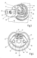
- a driver segment 35 is formed on the driver 21 on the front side with the hub 22, which is limited in the circumferential direction of the driver 21 by a respective driver lug 36.
- the driver segment 35 summarizes with its driving lugs 36 with play between the narrow sides of the Wedge segments 27.
- the running eccentric 31 is sickle-shaped and arranged axially between the driver 21 and the wedge segments 27. Two extending in the circumferential direction and the running eccentric 31 axially penetrating slots 37 allow play with the final fingers of the annular spring 30 unimpeded penetration into the holes 29 of the wedge segments 27, without coupling the wedge segments 27 with the running eccentric 31.
- two axially projecting pins 38 are formed on the driver 21 facing the end face, which are radially opposite each other. Each pin 38 engages in a circumferentially arranged slot 39. In the initial position, the pin 38 is arranged approximately in the middle of the slot 39. The pins 38 and slots 39 are arranged so that when a system of a pin 38 at the closer to the driver segment 35 located end of the associated slot 39 (in the Fig. 1 and 3 the lower end) of the running eccentric 31 is still spaced from the driving lug 36.
- a torque is first introduced into the driver 21 and then transmitted to the locking eccentric by one of the driving lugs 36, the associated wedge segment 27 is applied and compresses the wedge segments 27. If, with the further rotation of the driver 21, the idle travel predetermined by the oblong holes 39 is passed through, the running eccentric 31 is acted upon and taken along by the journal 38.
- a second modification to the first embodiment is similar to the first modification and the first embodiment, unless otherwise described, which is why the same components are provided with the same reference numerals and equivalent components with reference numerals with two apostrophes.
- the shape of the rockers 45 “conditionally causes the end fingers of the annular spring 30 to move toward one another until the wedge segments 27 abut each other, so that the blocking effect is canceled ,
- the running eccentric 31 in turn turns without lateral force.
- a third modification to the first embodiment is similar to the previous modifications and the first embodiment, unless otherwise described, which is why identical components are provided with the same reference numerals and equivalent components with reference numerals with three apostrophes.
- the driver 21 "' is coupled to a coupling point 48"' with a coupling 41 "', which is rotatably mounted on a link rocker 43"'.
- the link rocker 43 "' is slightly asymmetrical and has only one link 45"', on the side of the lower loaded wedge segment 27, while on the other side the link rocker 43 "'by means of the associated (left in the drawing) end finger the annular spring 30 is mounted in the higher loaded wedge segment 27.
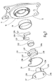
- a second embodiment is similar to the first embodiment, which is why identical components bear the same reference numerals and equivalent components by 200 higher reference numerals.
- the driver 221 is on the front side with the hub 222 a driver segment 235 formed, which is bounded in the circumferential direction of the driver 221 by a respective driver nose 236.
- the driver segment 235 seizes with its driving lugs 236 with clearance between the narrow sides of the wedge segments 227.
- the wedge segments 227 sit directly on the collar 19 of the first fitting part, while the first plain bearing bush 28 is in turn pressed into the second fitting part 12.
- the running eccentric 231 is annular and arranged axially between the driver 221 and the wedge segments 227.
- Two circumferentially extending and the running eccentric 231 axially penetrating slots 237 allow play with the end fingers of the annular spring 30 unimpeded penetration into the provided instead of holes, mouths opening 229 of the wedge segments 227, without coupling the wedge segments 227 with the running eccentric 231.
- On running eccentric 231 two axially projecting pin 238 are formed on the driver 221 facing end face, which are radially opposite each other. Each pin 238 engages positively in a circumferentially arranged hole 239.
- driver 221 and the barrel eccentric 231 are rotatably connected to each other, i. coupled to rotatable driving.
- the second plain bearing bushing 233 is pressed onto a hub-like, axial projection 231 b of the barrel eccentric 231 and disposed within the collar 19, i. stored in the collar 19.
- the hub 222 of the driver 221 is disposed within the barrel eccentric 231, i. the driver 221 is mounted with the interposition of the barrel eccentric 231 together with second plain bearing bushing 233 on the first fitting part 11.
- a third embodiment is similar to the first and second embodiments, unless otherwise described, why identical components bear the same reference numerals and equivalent components by 300 or 100 higher reference numerals.
- the driver 321 of the third embodiment is also designed as a running eccentric and takes over its tasks, i. Carrier and running eccentric are integrally formed or only different areas of the same component.
- a driver segment 335 is integrally formed on the front side with the hub 322, which is bounded in the circumferential direction of the driver 321 by a respective driver lug 336.
- the driver segment 335 grips with its driving lugs 336 with clearance between the narrow sides of the wedge segments 227.
- the wedge segments 227 sit directly on the collar 19 of the first fitting part, while the first plain bearing bush 28 is in turn pressed into the second fitting part 12.
- the second journal bearing sleeve 233 is pressed onto the hub 322 of the driver 321 and disposed within the collar 19, i. stored in the collar 19.
- Two circumferentially extending and the driver 321 axially penetrating slots 337 allow play with the final fingers of the annular spring 30 unimpeded penetration into the provided instead of holes, mouths opening 229 of the wedge segments 227, without at this point the wedge segments 227 with the driver 321 couple. In a modified embodiment, exactly this could be desirable, i. the slots 337 to be further developed scenes for the end fingers of the annular spring 30, holes in the wedge segments and be omitted the driver segment.
- a torque is introduced into the driver 321 and then transmitted to the locking eccentric by one of the driving lugs 336 acts on the associated wedge segment 227 and compresses the wedge segments 227. Due to the one-piece design, the driver rotates 321 free of lateral forces. It slides with substantially the same (less) friction on the plain bearing bushes 28 and 233, resulting in the rolling movement of the fitting parts 11 and 12 relative to each other.
Landscapes
- Engineering & Computer Science (AREA)
- Aviation & Aerospace Engineering (AREA)
- Transportation (AREA)
- Mechanical Engineering (AREA)
- Chairs For Special Purposes, Such As Reclining Chairs (AREA)
- Braking Arrangements (AREA)
- Seats For Vehicles (AREA)
Priority Applications (1)
| Application Number | Priority Date | Filing Date | Title |
|---|---|---|---|
| PL05804976T PL1827895T3 (pl) | 2004-12-23 | 2005-12-14 | Okucie siedzenia pojazdu |
Applications Claiming Priority (2)
| Application Number | Priority Date | Filing Date | Title |
|---|---|---|---|
| DE102004062049A DE102004062049A1 (de) | 2004-12-23 | 2004-12-23 | Beschlag für einen Fahrzeugsitz |
| PCT/EP2005/013428 WO2006069630A2 (de) | 2004-12-23 | 2005-12-14 | Beschlag für einen fahrzeugsitz |
Publications (2)
| Publication Number | Publication Date |
|---|---|
| EP1827895A2 EP1827895A2 (de) | 2007-09-05 |
| EP1827895B1 true EP1827895B1 (de) | 2010-11-03 |
Family
ID=36590470
Family Applications (1)
| Application Number | Title | Priority Date | Filing Date |
|---|---|---|---|
| EP05804976A Ceased EP1827895B1 (de) | 2004-12-23 | 2005-12-14 | Beschlag für einen fahrzeugsitz |
Country Status (8)
| Country | Link |
|---|---|
| US (1) | US20070298891A1 (zh) |
| EP (1) | EP1827895B1 (zh) |
| JP (1) | JP4568762B2 (zh) |
| KR (1) | KR101155672B1 (zh) |
| CN (1) | CN101087706B (zh) |
| DE (2) | DE102004062049A1 (zh) |
| PL (1) | PL1827895T3 (zh) |
| WO (1) | WO2006069630A2 (zh) |
Families Citing this family (13)
| Publication number | Priority date | Publication date | Assignee | Title |
|---|---|---|---|---|
| JP4720660B2 (ja) * | 2006-07-13 | 2011-07-13 | トヨタ紡織株式会社 | 連結装置 |
| DE102007039024B4 (de) * | 2007-01-04 | 2016-11-10 | Johnson Controls Gmbh | Verstelleinrichtung für eine Fahrzeugkomponente |
| DE102009053250B4 (de) * | 2009-11-10 | 2013-04-04 | Keiper Gmbh & Co. Kg | Beschlag für einen Fahrzeugsitz und Fahrzeugsitz |
| DE102010023966A1 (de) * | 2010-06-09 | 2011-12-15 | Keiper Gmbh & Co. Kg | Beschlag für einen Fahrzeugsitz |
| DE102011113747B4 (de) * | 2011-09-14 | 2025-01-23 | Keiper Seating Mechanisms Co., Ltd. | Beschlagsystem für einen Fahrzeugsitz und Fahrzeugsitz |
| KR101283186B1 (ko) * | 2011-12-21 | 2013-07-05 | 주식회사다스 | 차량용 리클라이너 장치 |
| DE102015217246B4 (de) | 2015-09-09 | 2018-09-27 | Continental Automotive Gmbh | Verfahren und Steuergerät |
| DE102018221238B4 (de) | 2018-12-07 | 2025-01-09 | Brose Fahrzeugteile SE & Co. Kommanditgesellschaft, Coburg | Drehbeschlag für einen Fahrzeugsitz, Fahrzeugsitz und Verfahren zur Herstellung eines solchen Drehbeschlags |
| US11845367B2 (en) | 2019-04-18 | 2023-12-19 | Fisher & Company, Incorporated | Recliner heart having lubricant member |
| US11766957B2 (en) | 2021-02-16 | 2023-09-26 | Fisher & Company, Incorporated | Release mechanism for seat recliner assembly |
| US11897372B2 (en) * | 2021-05-06 | 2024-02-13 | Fisher & Company, Incorporated | Recliner heart having biasing members |
| US11850975B2 (en) | 2021-06-11 | 2023-12-26 | Fisher & Company, Incorporated | Vehicle seat recliner mechanism with welded spring |
| KR102542569B1 (ko) * | 2021-08-10 | 2023-06-12 | 현대트랜시스 주식회사 | 차량의 시트 리클라이너 |
Family Cites Families (20)
| Publication number | Priority date | Publication date | Assignee | Title |
|---|---|---|---|---|
| DE3914084A1 (de) * | 1989-04-28 | 1990-10-31 | Keiper Recaro Gmbh Co | Uebertragungswelle fuer auf beiden seiten eines sitzes angeordnete gelenkbeschlaege |
| US5277672A (en) * | 1989-06-30 | 1994-01-11 | Ets. Cousin Freres | Clearance take up device for so-called continuous epicycloidal train articulations, and its mounting mode |
| DE3941215C2 (de) * | 1989-12-14 | 1995-07-20 | Keiper Recaro Gmbh Co | Rücklehnenverstellbeschlag für Sitze, insbesondere Kraftfahrzeugsitze |
| DE4138420C2 (de) * | 1991-09-05 | 2001-03-08 | Faure Bertrand Sitztech Gmbh | Verstellbeschlag für Kraftfahrzeugsitze |
| JP3477747B2 (ja) * | 1993-07-13 | 2003-12-10 | アイシン精機株式会社 | 噛合継手 |
| US5524970A (en) * | 1994-08-10 | 1996-06-11 | Hoover Universal, Inc. | Rotary recliner |
| DE19517441C1 (de) * | 1995-05-12 | 1996-10-02 | Keiper Recaro Gmbh Co | Gelenkbeschlag für Sitze mit verstellbarer Rückenlehne, insbesondere Kraftfahrzeugsitze |
| DE19548809C1 (de) * | 1995-12-27 | 1997-05-22 | Keiper Recaro Gmbh Co | Ver- und Feststelleinrichtung für Sitze, wie Kraftfahrzeugsitze, zur Verstellung der Rückenlehne |
| JP3540952B2 (ja) * | 1998-12-21 | 2004-07-07 | 富士機工株式会社 | 車両用座席装置の調節及び固定装置 |
| DE19938666C5 (de) * | 1999-08-14 | 2008-01-03 | Keiper Gmbh & Co.Kg | Verstellbeschlag für Sitze mit neigungseinstellbarer Lehne, insbesondere für Kraftfahzeugsitze |
| JP2002010851A (ja) | 2000-06-29 | 2002-01-15 | Fuji Kiko Co Ltd | 車両用シートリクライニング装置 |
| US6830298B2 (en) * | 2001-02-21 | 2004-12-14 | Faurecia Autositze Gmbh & Co. | Adjustment-locking mechanism for an automobile seat back |
| JP4766765B2 (ja) | 2001-03-30 | 2011-09-07 | 富士機工株式会社 | 車両用シートリクライニング装置及びその製造方法 |
| JP2003009978A (ja) | 2001-04-23 | 2003-01-14 | Aisin Seiki Co Ltd | シートリクライニング装置 |
| JP4170906B2 (ja) * | 2001-09-06 | 2008-10-22 | カイペル ゲーエムベーハー アンド カンパニー カーゲー | 車両座席用取り付け具およびそれを備えた車両座席 |
| JP3936227B2 (ja) * | 2002-04-11 | 2007-06-27 | シロキ工業株式会社 | リクライニング機構 |
| JP4336503B2 (ja) * | 2003-01-31 | 2009-09-30 | 富士機工株式会社 | シートリクライニング装置 |
| DE10328300B4 (de) * | 2003-06-23 | 2006-09-21 | Faurecia Autositze Gmbh & Co. Kg | Verstellbeschlag für Kraftfahrzeugsitz |
| KR100549199B1 (ko) * | 2003-11-26 | 2006-02-02 | 주식회사다스 | 컨티뉴즐리타입 자동차용 시트 리클라이닝장치 |
| US7086699B1 (en) * | 2004-12-21 | 2006-08-08 | Dura Global Technologies, Inc. | Recliner assembly for vehicle seats |
-
2004
- 2004-12-23 DE DE102004062049A patent/DE102004062049A1/de not_active Withdrawn
-
2005
- 2005-12-14 DE DE502005010497T patent/DE502005010497D1/de active Active
- 2005-12-14 PL PL05804976T patent/PL1827895T3/pl unknown
- 2005-12-14 CN CN2005800448178A patent/CN101087706B/zh not_active Expired - Fee Related
- 2005-12-14 WO PCT/EP2005/013428 patent/WO2006069630A2/de active Application Filing
- 2005-12-14 JP JP2007547275A patent/JP4568762B2/ja not_active Expired - Fee Related
- 2005-12-14 KR KR1020077009353A patent/KR101155672B1/ko not_active IP Right Cessation
- 2005-12-14 EP EP05804976A patent/EP1827895B1/de not_active Ceased
-
2007
- 2007-06-22 US US11/821,427 patent/US20070298891A1/en not_active Abandoned
Also Published As
| Publication number | Publication date |
|---|---|
| PL1827895T3 (pl) | 2011-03-31 |
| DE502005010497D1 (de) | 2010-12-16 |
| JP4568762B2 (ja) | 2010-10-27 |
| DE102004062049A1 (de) | 2006-07-06 |
| WO2006069630A2 (de) | 2006-07-06 |
| CN101087706B (zh) | 2011-05-25 |
| JP2008525065A (ja) | 2008-07-17 |
| EP1827895A2 (de) | 2007-09-05 |
| WO2006069630A3 (de) | 2007-05-10 |
| CN101087706A (zh) | 2007-12-12 |
| KR101155672B1 (ko) | 2012-06-13 |
| KR20070083791A (ko) | 2007-08-24 |
| US20070298891A1 (en) | 2007-12-27 |
Similar Documents
| Publication | Publication Date | Title |
|---|---|---|
| EP1827896B1 (de) | Beschlag für einen fahrzeugsitz | |
| EP1202870B9 (de) | Verstellbeschlag für sitze mit neigungseinstellbarer lehne, insbesondere für kraftfahrzeugsitze | |
| EP1893437B1 (de) | Beschlag für einen fahrzeugsitz | |
| EP1928691B1 (de) | Beschlag für einen fahrzeugsitz | |
| DE102005046807B3 (de) | Beschlag für einen Fahrzeugsitz | |
| DE69506189T2 (de) | Drehbare Neigung | |
| DE69619339T2 (de) | Neigungsverstellvorrichtung für Sitze | |
| EP1827895B1 (de) | Beschlag für einen fahrzeugsitz | |
| DE102005054490B4 (de) | Beschlag für einen Fahrzeugsitz | |
| DE602006000028T2 (de) | Sitzneigungsverstellvorrichtung für Fahrzeuge | |
| DE102006044490A1 (de) | Beschlag für einen Fahrzeugsitz | |
| DE20023454U1 (de) | Rastbeschlag für einen Fahrzeugsitz | |
| WO2004056605A1 (de) | Antrieb mit schubelement für einen fahrzeugsitzeinsteller | |
| EP1144219A1 (de) | Stelleinrichtung, insbesondere zur verstellung eines kraftfahrzeugsitzes | |
| DE102009002478B4 (de) | Ver- und Feststellvorrichtung eines Verstellbeschlages | |
| EP2193043A2 (de) | Rastbeschlag und mit rastbeschlag ausgestatteter fahrzeugsitz | |
| DE10157274B4 (de) | Verstellbeschlag für Kraftfahrzeugsitze | |
| DE102023101988A1 (de) | Einrichtung zum Verstellen der Neigung einer Rückenlehne in Bezug auf eine Sitzfläche eines Sitzes | |
| EP1240050A1 (de) | Beidseitig wirkender antrieb für verstellvorrichtungen in kraftfahrzeugen | |
| DE3401646A1 (de) | Drehgelenk, insbesondere fuer sitze mit verstellbarer rueckenlehne | |
| DE202005010561U1 (de) | Verstellbeschlag |
Legal Events
| Date | Code | Title | Description |
|---|---|---|---|
| PUAI | Public reference made under article 153(3) epc to a published international application that has entered the european phase |
Free format text: ORIGINAL CODE: 0009012 |
|
| 17P | Request for examination filed |
Effective date: 20070320 |
|
| AK | Designated contracting states |
Kind code of ref document: A2 Designated state(s): AT BE BG CH CY CZ DE DK EE ES FI FR GB GR HU IE IS IT LI LT LU LV MC NL PL PT RO SE SI SK TR |
|
| AX | Request for extension of the european patent |
Extension state: AL BA HR MK YU |
|
| RIN1 | Information on inventor provided before grant (corrected) |
Inventor name: NORBISRATH, ANDREAS Inventor name: STEMMER, JUERGEN Inventor name: MESSERSCHMIDT, RAINER Inventor name: VOSS, HEINZ Inventor name: LEHMANN, ULRICH Inventor name: SCHOLZ, GRIT Inventor name: EWALD, TOBIAS Inventor name: KOMAINDA, ARTUR |
|
| DAX | Request for extension of the european patent (deleted) | ||
| RBV | Designated contracting states (corrected) |
Designated state(s): DE FR GB PL |
|
| 17Q | First examination report despatched |
Effective date: 20080408 |
|
| GRAP | Despatch of communication of intention to grant a patent |
Free format text: ORIGINAL CODE: EPIDOSNIGR1 |
|
| GRAS | Grant fee paid |
Free format text: ORIGINAL CODE: EPIDOSNIGR3 |
|
| GRAA | (expected) grant |
Free format text: ORIGINAL CODE: 0009210 |
|
| AK | Designated contracting states |
Kind code of ref document: B1 Designated state(s): DE FR GB PL |
|
| REG | Reference to a national code |
Ref country code: GB Ref legal event code: FG4D Free format text: NOT ENGLISH |
|
| REF | Corresponds to: |
Ref document number: 502005010497 Country of ref document: DE Date of ref document: 20101216 Kind code of ref document: P |
|
| REG | Reference to a national code |
Ref country code: PL Ref legal event code: T3 |
|
| PGFP | Annual fee paid to national office [announced via postgrant information from national office to epo] |
Ref country code: PL Payment date: 20101206 Year of fee payment: 6 |
|
| PLBE | No opposition filed within time limit |
Free format text: ORIGINAL CODE: 0009261 |
|
| STAA | Information on the status of an ep patent application or granted ep patent |
Free format text: STATUS: NO OPPOSITION FILED WITHIN TIME LIMIT |
|
| 26N | No opposition filed |
Effective date: 20110804 |
|
| REG | Reference to a national code |
Ref country code: DE Ref legal event code: R097 Ref document number: 502005010497 Country of ref document: DE Effective date: 20110804 |
|
| REG | Reference to a national code |
Ref country code: DE Ref legal event code: R082 Ref document number: 502005010497 Country of ref document: DE |
|
| REG | Reference to a national code |
Ref country code: PL Ref legal event code: LAPE |
|
| PG25 | Lapsed in a contracting state [announced via postgrant information from national office to epo] |
Ref country code: PL Free format text: LAPSE BECAUSE OF NON-PAYMENT OF DUE FEES Effective date: 20111214 |
|
| REG | Reference to a national code |
Ref country code: DE Ref legal event code: R081 Ref document number: 502005010497 Country of ref document: DE Owner name: JOHNSON CONTROLS COMPONENTS GMBH & CO. KG, DE Free format text: FORMER OWNER: KEIPER GMBH & CO. KG, 67657 KAISERSLAUTERN, DE Effective date: 20140710 Ref country code: DE Ref legal event code: R081 Ref document number: 502005010497 Country of ref document: DE Owner name: ADIENT LUXEMBOURG HOLDING S.A.R.L., LU Free format text: FORMER OWNER: KEIPER GMBH & CO. KG, 67657 KAISERSLAUTERN, DE Effective date: 20140710 Ref country code: DE Ref legal event code: R081 Ref document number: 502005010497 Country of ref document: DE Owner name: ADIENT LUXEMBOURG HOLDING S.A R.L., LU Free format text: FORMER OWNER: KEIPER GMBH & CO. KG, 67657 KAISERSLAUTERN, DE Effective date: 20140710 |
|
| REG | Reference to a national code |
Ref country code: FR Ref legal event code: PLFP Year of fee payment: 11 |
|
| REG | Reference to a national code |
Ref country code: FR Ref legal event code: PLFP Year of fee payment: 12 |
|
| PGFP | Annual fee paid to national office [announced via postgrant information from national office to epo] |
Ref country code: GB Payment date: 20161222 Year of fee payment: 12 |
|
| REG | Reference to a national code |
Ref country code: DE Ref legal event code: R081 Ref document number: 502005010497 Country of ref document: DE Owner name: ADIENT LUXEMBOURG HOLDING S.A.R.L., LU Free format text: FORMER OWNER: JOHNSON CONTROLS COMPONENTS GMBH & CO. KG, 67657 KAISERSLAUTERN, DE Ref country code: DE Ref legal event code: R081 Ref document number: 502005010497 Country of ref document: DE Owner name: ADIENT LUXEMBOURG HOLDING S.A R.L., LU Free format text: FORMER OWNER: JOHNSON CONTROLS COMPONENTS GMBH & CO. KG, 67657 KAISERSLAUTERN, DE |
|
| REG | Reference to a national code |
Ref country code: FR Ref legal event code: PLFP Year of fee payment: 13 |
|
| PGFP | Annual fee paid to national office [announced via postgrant information from national office to epo] |
Ref country code: FR Payment date: 20171228 Year of fee payment: 13 |
|
| REG | Reference to a national code |
Ref country code: DE Ref legal event code: R081 Ref document number: 502005010497 Country of ref document: DE Owner name: ADIENT LUXEMBOURG HOLDING S.A R.L., LU Free format text: FORMER OWNER: ADIENT LUXEMBOURG HOLDING S.A.R.L., LUXEMBOURG, LU |
|
| PGFP | Annual fee paid to national office [announced via postgrant information from national office to epo] |
Ref country code: DE Payment date: 20171231 Year of fee payment: 13 |
|
| GBPC | Gb: european patent ceased through non-payment of renewal fee |
Effective date: 20171214 |
|
| PG25 | Lapsed in a contracting state [announced via postgrant information from national office to epo] |
Ref country code: GB Free format text: LAPSE BECAUSE OF NON-PAYMENT OF DUE FEES Effective date: 20171214 |
|
| REG | Reference to a national code |
Ref country code: DE Ref legal event code: R119 Ref document number: 502005010497 Country of ref document: DE |
|
| PG25 | Lapsed in a contracting state [announced via postgrant information from national office to epo] |
Ref country code: DE Free format text: LAPSE BECAUSE OF NON-PAYMENT OF DUE FEES Effective date: 20190702 Ref country code: FR Free format text: LAPSE BECAUSE OF NON-PAYMENT OF DUE FEES Effective date: 20181231 |