EP1818573A2 - Steuereinrichtung für ein automatisches Getriebe - Google Patents
Steuereinrichtung für ein automatisches Getriebe Download PDFInfo
- Publication number
- EP1818573A2 EP1818573A2 EP07000126A EP07000126A EP1818573A2 EP 1818573 A2 EP1818573 A2 EP 1818573A2 EP 07000126 A EP07000126 A EP 07000126A EP 07000126 A EP07000126 A EP 07000126A EP 1818573 A2 EP1818573 A2 EP 1818573A2
- Authority
- EP
- European Patent Office
- Prior art keywords
- disengagement
- malfunction
- frictional engaging
- automatic transmission
- speed
- Prior art date
- Legal status (The legal status is an assumption and is not a legal conclusion. Google has not performed a legal analysis and makes no representation as to the accuracy of the status listed.)
- Granted
Links
Images



Classifications
-
- F—MECHANICAL ENGINEERING; LIGHTING; HEATING; WEAPONS; BLASTING
- F16—ENGINEERING ELEMENTS AND UNITS; GENERAL MEASURES FOR PRODUCING AND MAINTAINING EFFECTIVE FUNCTIONING OF MACHINES OR INSTALLATIONS; THERMAL INSULATION IN GENERAL
- F16H—GEARING
- F16H61/00—Control functions within control units of change-speed- or reversing-gearings for conveying rotary motion ; Control of exclusively fluid gearing, friction gearing, gearings with endless flexible members or other particular types of gearing
- F16H61/12—Detecting malfunction or potential malfunction, e.g. fail safe ; Circumventing or fixing failures
-
- F—MECHANICAL ENGINEERING; LIGHTING; HEATING; WEAPONS; BLASTING
- F16—ENGINEERING ELEMENTS AND UNITS; GENERAL MEASURES FOR PRODUCING AND MAINTAINING EFFECTIVE FUNCTIONING OF MACHINES OR INSTALLATIONS; THERMAL INSULATION IN GENERAL
- F16H—GEARING
- F16H61/00—Control functions within control units of change-speed- or reversing-gearings for conveying rotary motion ; Control of exclusively fluid gearing, friction gearing, gearings with endless flexible members or other particular types of gearing
-
- F—MECHANICAL ENGINEERING; LIGHTING; HEATING; WEAPONS; BLASTING
- F16—ENGINEERING ELEMENTS AND UNITS; GENERAL MEASURES FOR PRODUCING AND MAINTAINING EFFECTIVE FUNCTIONING OF MACHINES OR INSTALLATIONS; THERMAL INSULATION IN GENERAL
- F16H—GEARING
- F16H59/00—Control inputs to control units of change-speed- or reversing-gearings for conveying rotary motion
- F16H59/68—Inputs being a function of gearing status
- F16H59/70—Inputs being a function of gearing status dependent on the ratio established
- F16H2059/706—Monitoring gear ratio in stepped transmissions, e.g. by calculating the ratio from input and output speed
-
- F—MECHANICAL ENGINEERING; LIGHTING; HEATING; WEAPONS; BLASTING
- F16—ENGINEERING ELEMENTS AND UNITS; GENERAL MEASURES FOR PRODUCING AND MAINTAINING EFFECTIVE FUNCTIONING OF MACHINES OR INSTALLATIONS; THERMAL INSULATION IN GENERAL
- F16H—GEARING
- F16H61/00—Control functions within control units of change-speed- or reversing-gearings for conveying rotary motion ; Control of exclusively fluid gearing, friction gearing, gearings with endless flexible members or other particular types of gearing
- F16H61/12—Detecting malfunction or potential malfunction, e.g. fail safe ; Circumventing or fixing failures
- F16H2061/122—Avoiding failures by using redundant parts
-
- F—MECHANICAL ENGINEERING; LIGHTING; HEATING; WEAPONS; BLASTING
- F16—ENGINEERING ELEMENTS AND UNITS; GENERAL MEASURES FOR PRODUCING AND MAINTAINING EFFECTIVE FUNCTIONING OF MACHINES OR INSTALLATIONS; THERMAL INSULATION IN GENERAL
- F16H—GEARING
- F16H61/00—Control functions within control units of change-speed- or reversing-gearings for conveying rotary motion ; Control of exclusively fluid gearing, friction gearing, gearings with endless flexible members or other particular types of gearing
- F16H61/12—Detecting malfunction or potential malfunction, e.g. fail safe ; Circumventing or fixing failures
- F16H2061/1232—Bringing the control into a predefined state, e.g. giving priority to particular actuators or gear ratios
-
- F—MECHANICAL ENGINEERING; LIGHTING; HEATING; WEAPONS; BLASTING
- F16—ENGINEERING ELEMENTS AND UNITS; GENERAL MEASURES FOR PRODUCING AND MAINTAINING EFFECTIVE FUNCTIONING OF MACHINES OR INSTALLATIONS; THERMAL INSULATION IN GENERAL
- F16H—GEARING
- F16H61/00—Control functions within control units of change-speed- or reversing-gearings for conveying rotary motion ; Control of exclusively fluid gearing, friction gearing, gearings with endless flexible members or other particular types of gearing
- F16H61/12—Detecting malfunction or potential malfunction, e.g. fail safe ; Circumventing or fixing failures
- F16H2061/1256—Detecting malfunction or potential malfunction, e.g. fail safe ; Circumventing or fixing failures characterised by the parts or units where malfunctioning was assumed or detected
- F16H2061/1276—Detecting malfunction or potential malfunction, e.g. fail safe ; Circumventing or fixing failures characterised by the parts or units where malfunctioning was assumed or detected the failing part is a friction device, e.g. clutches or brakes
-
- Y—GENERAL TAGGING OF NEW TECHNOLOGICAL DEVELOPMENTS; GENERAL TAGGING OF CROSS-SECTIONAL TECHNOLOGIES SPANNING OVER SEVERAL SECTIONS OF THE IPC; TECHNICAL SUBJECTS COVERED BY FORMER USPC CROSS-REFERENCE ART COLLECTIONS [XRACs] AND DIGESTS
- Y10—TECHNICAL SUBJECTS COVERED BY FORMER USPC
- Y10S—TECHNICAL SUBJECTS COVERED BY FORMER USPC CROSS-REFERENCE ART COLLECTIONS [XRACs] AND DIGESTS
- Y10S477/00—Interrelated power delivery controls, including engine control
- Y10S477/906—Means detecting or ameliorating the effects of malfunction or potential malfunction
Definitions
- the present invention generally relates to a control system for an automatic transmission. More specifically, the present invention relates to an automatic transmission control system for preventing disengagement malfunction of a frictional engaging element.
- a disengagement malfunction of one (first) frictional engaging element may cause a secondary malfunction of a disengagement malfunction of another (second) frictional engaging element.
- disengagement malfunction refers to a malfunction in which a frictional engaging element remains engaged irrespective of a release command, encompassing not only a state in which it remains fully engaged (no relative rotation) but also a state in which it remains partially engaged to allow transmission of a portion of power.
- one of the frictional engaging elements is produced with a torque transmission capacity higher than required for normal torque transmission in order to avoid occurrence of disengagement malfunction in this the frictional engaging element.
- the frictional engaging element is produced with additional capacity to prevent the disengagement malfunction due to another frictional engaging element having a disengagement malfunction.
- one object to provide an automatic transmission control system for an automatic transmission which detects an event in time when a disengagement malfunction of a first frictional engaging element occurred, and prevents a disengagement malfunction of a second frictional engaging element, without raising a required torque transmission capacity of the second frictional engaging elements higher than needed.
- an automatic transmission control system that basically comprises a disengagement malfunction determining section and a disengagement malfunction preventing section.
- the disengagement malfunction determining section is configured to determine a disengagement malfunction with a first frictional engaging element from among a plurality of frictional engaging elements of an automatic transmission in which the frictional engaging elements are selectively engaged and disengaged to change a rotational speed of a main power source.
- the disengagement malfunction preventing section is configured to prevent disengagement malfunction of a second frictional engaging element from among the frictional engaging elements of the automatic transmission by lowering the rotational speed of the main power source to a level which will prevent the disengagement malfunction in the second frictional engaging element, when the disengagement malfunction determining section determines that the disengagement malfunction of the first frictional engaging element exist while the automatic transmission is in non-running range.
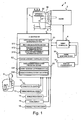
- Figure 1 is a schematic view of a vehicle power train of a vehicle equipped with an automatic transmission control system in accordance with a first embodiment of the present invention
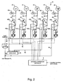
- FIG. 2 is a hydraulic pressure circuit diagram of the automatic transmission in accordance with the first embodiment of the present invention.
- Figure 3 is a schematic skeleton diagram illustrating a change-speed planetary gearing of the automatic transmission that is used with the automatic transmission control system in accordance with the illustrated embodiment of the present invention
- Figure 4 is a frictional (clutch and brake) engagement operating chart for the automatic transmission that is used with the automatic transmission control system in accordance with the illustrated embodiment of the present invention for showing the relationship between a combination of engagement and release of each of the transmission frictional engagement elements and each shifting step;
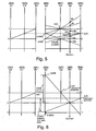
- Figure 5 is a speed shifting diagram representing operation of the change-speed planetary gearing
- Figure 6 is a speed shifting diagram representing operation of the change-speed planetary gearing when disengagement malfunction occurs
- FIG. 7 is a flowchart showing an automatic transmission control program executed by the automatic transmission control system during engine starting in accordance with the illustrated embodiment of the present invention.
- Figure 8 is a graph the plots engine rotational speed versus time to show a change in the engine rotational speed over time due to outputting a fuel-cut command signal and stopping the output of the fuel-cut command signal;
- a vehicle power train 1 is schematically illustrated that is equipped with an automatic transmission control system in accordance with a first embodiment of the present invention.
- the vehicle power train 1 has an engine 2 that is a main power source, an automatic transmission 3, an engine controller 4, an automatic transmission controller 5, a gear position selection lever 6 and various sensors 10 ⁇ 16.
- the automatic transmission 3, which features transverse mounting for a front engine front drive system, has a torque converter 30, a change-speed planetary gearing 31 (see Figure 3), a final gear (not shown) and a differential gear (not shown). Via the torque converter 30, engine torque is input to an input shaft IN of the automatic transmission 3.
- the change-speed planetary gearing 31 changes speed of input rotation at a gear ratio of a selected one of shifting steps, transmitting torque to an output shaft (not shown).
- the various sensors 10 ⁇ 16 includes an engine rotational speed sensor 10, a throttle position sensor 11, a range position sensor 12, a turbine speed sensor 13, a vehicle speed sensor 14, a brake sensor (a brake pedal switch) 15 and a hydraulic pressure sensor or switch 16.
- the engine rotational speed sensor 10 is configured and arranged to detect an engine rotational speed of the engine 2, and produce a control signal indicative of the engine rotational speed of the engine 2 that is sent to the engine controller 4.
- the throttle position sensor 11 is configured and arranged to detect a throttle position, and produce a control signal indicative of the throttle position that is sent to the engine controller 4.
- the range position sensor 12 is configured and arranged to detect the range which has been selected by a driver manipulation of the gear position selection lever 6 or the shifting steps which has been selected, and produce a control signal indicative of the selected gear range position that is sent to the automatic transmission controller 5.
- the turbine speed sensor 13 is configured and arranged to detect rotational speed of the automatic transmission input shaft IN, and produce a control signal indicative of the rotational speed of the turbine 30 that is sent to the automatic transmission controller 5.
- the vehicle speed sensor 14 is configured and arranged to detect the rotational speed of the automatic transmission output shaft, and produce a control signal indicative of the vehicle speed that is sent to the automatic transmission controller 5.
- the brake sensor 15 is configured and arranged to detect the driver depressing the brake pedal, and produce a control signal indicative of the driver depressing the brake pedal that is sent to the automatic transmission controller 5.
- the hydraulic pressure sensor 16 is configured and arranged to detect a hydraulic pressure (described later), and produce a control signal indicative of the hydraulic pressure that is sent to the automatic transmission controller 5.
- the engine controller 4 receives the detected signals from the engine rotational speed sensor 10 and the throttle position sensor 11, and outputs control signal for the engine 2 for controlling the engine rotational speed and etc. In addition, it outputs an engine rotational speed signal and a throttle position signal for the automatic transmission controller 5.
- the automatic transmission controller 5 performs shifting control. That is to say, firstly, the automatic transmission controller 5 determines a target shifting step by referring to a shift schedule, which has been set beforehand and memorized therein, based on the vehicle speed signal and throttle position signal. Secondary, the automatic transmission controller 5 outputs a shift command signal for the automatic transmission 3, executing a shift by controlling engagement and release (disengagement) of the frictional engaging elements, accomplishing the above-mentioned target shifting step.
- the automatic transmission controller 5 inputs the respective detected signals from the range position sensor 12, the turbine speed sensor 13, the vehicle speed sensor 14, the brake switch 15 and the hydraulic fluid pressure sensor 16 and carries out operation processing based on these signals.
- the automatic transmission controller 5 calculates vehicle speed and vehicle deceleration based on the rotational speed of the output shaft speed detected by the vehicle speed sensor 14.
- the automatic transmission controller 5 calculates a gear ratio based on the turbine rotational speed detected by the turbine speed sensor 13 and the output shaft rotational speed detected by the vehicle speed sensor 14.
- the controllers 4 and 5 each preferably include a microcomputer with a control program that controls the power train 1 as discussed below.
- the controllers 4 and 5 also include other conventional components such as an input interface circuit, an output interface circuit, and storage devices such as a ROM (Read Only Memory) device and a RAM (Random Access Memory) device. While the controllers 4 and 5 are shown as separate units, the controllers 4 and 5 can be a single integrated unit. It will be apparent to those skilled in the art from this disclosure that the precise structure and algorithms for the controllers 4 and 5 can be any combination of hardware and software that will carry out the functions of the present invention. In other words, "means plus function" clauses as utilized in the specification and claims should include any structure or hardware and/or algorithm or software that can be utilized to carry out the function of the "means plus function” clause.
- FIG. 2 shows a hydraulic pressure circuit 32 via which the automatic transmission controller 5 controls engagement and release of the frictional engaging elements.
- the hydraulic pressure circuit 32 is provided with a plurality of hydraulic pressure control valves 40 ⁇ 44 for the respective plurality of frictional engaging elements.
- the automatic transmission controller 5 outputs signals to these hydraulic pressure control valves 40 ⁇ 44, controlling open or close of them, controlling hydraulic pressures supplied to the frictional engaging elements.
- Each element namely, a low clutch L/C, a high clutch H/C, a 2-6 brake 2-6/B, a 3-5 reverse clutch 3-5R/C, and a low & reverse brake L&R/B, is engaged when a D range pressure or a R range pressure, which is an engagement pressure, is supplied to its piston chamber 20 ⁇ 24 and the element is released when the pressure is drained from the piston chamber.
- a D range pressure or a R range pressure which is an engagement pressure
- Line pressure PL is supplied to a manual valve 46 via a line-pressure hydraulic line 60.
- a D range pressure which appears only when a D range position is selected, and an R range pressure, which appears only when an R range position is selected, is the line pressure PL which appears after passing through the manual valve 46.
- the line pressure PL is supplied also to a pilot valve 45, and the pilot valve 45 regulates the line pressure PL to let a pilot pressure occur.
- the hydraulic pressure control valves 40 ⁇ 44 namely the first ⁇ fifth hydraulic control valves, for the respective frictional engaging elements control engagement pressures supplied to the above-mentioned engagement piston chambers 20 ⁇ 24, respectively.
- the first ⁇ third hydraulic pressure control valves 40 ⁇ 42 are supplied with D range pressure coming from the manual valve 46 through a D range pressure hydraulic line 62. It is made possible that the fourth hydraulic pressure control valve 43 is supplied with the line pressure PL directly or it is supplied with R range pressure coming from the manual valve 46.
- the fifth hydraulic pressure control valve 44 is supplied with the line pressure PL directly.
- each of the hydraulic pressure control valves 40 ⁇ 44 is supplied with the pilot pressure coming through the pilot pressure hydraulic line 61.
- the first hydraulic pressure control valve 40 includes a duty solenoid 40a and a hydraulic pressure regulator valve 40b.
- the second ⁇ fifth hydraulic pressure control valves 41 ⁇ 44 include duty solenoids 41a ⁇ 44a and hydraulic pressure regulator valves 41b ⁇ 44b, respectively.
- the duty solenoids 40a ⁇ 44a produce the respective shift control pressures depending on the respective solenoid forces.
- the hydraulic pressure regulator valves 40b ⁇ 42b of the first ⁇ third pressure control valves 40 ⁇ 42 regulate engaging pressures applied to the engaging piston chambers 20 ⁇ 22, respectively.
- the hydraulic pressure regulator valve 43b of the fourth pressure control valve 43 regulates engaging pressure applied to the engaging piston chamber 23 when the D range position is selected.
- R range pressure as a working signal pressure, it supplies line pressure PL, which is R range pressure, to the 3-5 reverse clutch 3-5R/C as it is when the R range position is selected.
- the hydraulic pressure regulator valve 44b of the fifth hydraulic pressure control valve 44 regulates engaging pressure applied to the engaging piston chamber 24.
- Hydraulic lines 65 ⁇ 69 which connect the respective hydraulic pressure control valves 40 ⁇ 44 to the associated engaging piston chambers 20 ⁇ 24, are equipped with hydraulic pressure switches 16a ⁇ 16e for the frictional engaging elements, respectively.
- the hydraulic pressure switches 16a ⁇ 16e detect whether or not the engaging pressures supplied to the respective frictional engaging elements are greater than or equal to a predetermined value, outputting an ON switch signal indicative of presence of engaging pressure (greater than or equal to the predetermined value) or an OFF switch signal indicative of absence of engaging pressure (less than the predetermined value) to the automatic transmission controller 5.
- the automatic transmission controller 5 outputs a control signal to the engine controller 4, controlling the engine 2 through the engine controller 4.
- the automatic transmission 3 is equipped with the select lever 6, making it possible for the driver to perform selection of each of P (parking) range, R (reverse) range, N (neutral) range, D (drive) range and M (manual) range manually by operating this select lever 6.
- the range position sensor 12 such as an inhibitor switch converts operation of the select lever 6 into a range position signal, outputting this range position signal to the automatic transmission controller 5.
- an automatic shifting control of six shifting steps, 1 speed ⁇ 6 speed, is performed based on a shift command signal for the automatic transmission 3, which is outputted in accordance with a shift schedule.
- the automatic shifting control When M range is selected, the automatic shifting control is not operated, allowing, irrespective of the shift schedule, a shift to a shifting step that is selected by the select lever 6. Selecting the M range makes engine braking effective while driving in first gear (speed).
- the range position sensor 12 converts selection of a shifting step into a shift position signal, outputting this shift position signal to the automatic transmission controller 5.
- Figure 3 is a skeleton diagram showing a power train of the change-speed planetary gearing 31 of the automatic transmission 3.
- the change-speed planetary gearing 31 includes a simple planetary gear set G 1 and a Ravigneaux planetary gear set G2.
- the planetary gear set G1 includes a first sun gear S1, a first carrier C1, and a first ring gear R1, providing a reduced rotation, as an input, to the planetary gear set G2.
- the planetary gear set G2 includes a large diameter second sun gear S2, a small diameter third sun gear S3, a second carrier C2, and a second ring gear R2.
- the second carrier C2 supports a plurality of pairs, each pair including a short pinion P and a long pinion P2. Each short pinion P 1 meshes with the third sun gear S3 and each long pinion P2 meshes with the second sun gear S2.
- the input shaft IN which inputs engine torque via a torque converter, is directly connected to the first ring gear R1 via a first member M1.
- the inputs shaft IN is connected to the second carrier C2 via a second member M2 and a high clutch H/C.
- the first carrier C1 is connected to the third sun gear S3 via a third member M3, a low clutch L/C and a fifth member M5.
- the first carrier C 1 is connected to the second sun gear S2 via the third member M3, a 3-5 reverse clutch 3-5R/C and a sixth member M6.
- the first sun gear S 1 is fixed to a transmission case TC via a fourth member M4.
- a sixth member M6 can be fixed to and released from its fixed connection to the transmission case TC via a 2-6 brake 2-6/B.
- the second carrier C2 is rotatably supported with respect to the transmission case TC via a seventh member M7 and a low reverse brake L&R/B such that its rotation can be fixed or released.
- the second carrier C2 is rotatably supported for rotation in one direction only with respect to the transmission case TC via the seventh member M7 and a low one-way clutch L/OWC such that its direction of rotation can be regulated.
- the low & reverse brake L&R/B and low one-way clutch L/OWC are arranged in parallel such that one operation of the two can be selected.
- the second ring gear R2 is connected to an output gear OUT via an eighth member M8.
- the automatic transmission 3 which has been constituted as mentioned above, realizes shifting steps, 6-speed (1st ⁇ 6th) forward and 1-speed reverse (Rev) by engaging or releasing each of the frictional engaging elements in accordance with various combinations as shown in Figure 4.
- a O mark indicates that a frictional engaging element is engaged;
- a no-mark indicates that a frictional engaging element is released;
- a ⁇ mark indicates that engagement of a frictional engaging element is effective during engine braking;
- a • mark indicates that a frictional engaging element is mechanically engaged (rotation regulation) only during engine driving.
- Figure 5 shows how the change-speed planetary gearing 31 works due to engagement or release of each frictional engaging element in a speed diagram (collinear diagram).
- This speed diagram has a plurality of parallel vertical axes. These parallel vertical axes indicate the frictional engaging elements, respectively, by the corresponding reference characters that have been placed near top ends thereof, and they indicate the rotary elements also, which are connected directly to these elements, by the reference characters that have been written in parentheses.
- the speed diagram shows a gear ratio between any two of these frictional engaging elements also by a width between the two of the parallel vertical axes which indicate the two frictional engaging elements.
- the speed diagram shows the speed ratio of each of these frictional engaging elements which assumes input rotational speed, which is applied to the change-speed planetary gearing 31, (rotational speed of the input shaft IN) 1 by length along the one of the parallel vertical axes which indicates the element.
- a positive value on each vertical axis indicates a rotation of the frictional engaging element which is indicated by the vertical axis in the same direction as the input shaft IN, and a negative value on the vertical axis indicates a rotation of the frictional engaging element in the opposite direction to the input shaft IN.
- a • mark indicates that each frictional engaging element is engaged, and a O mark indicates an output rotation at the shifting step.
- Shifting steps at low speed side are accomplished by selectively engaging other frictional engaging elements together with engaging the low clutch L/C, so a reduced speed rotation is fed to the third sun gear S3 when the low clutch L/C is engaged, it is subjected to a further change in speed due to selectively engaging other frictional engaging elements, and the further changed reduced speed rotation is outputted to an output gear OUT.
- First speed (1st) is accomplished by engaging the low & reverse brake L&R/B or the low one-way clutch L/WC together with engaging the low clutch L/C.
- Engine rotation is reduced in the process of passing from the input shaft IN through the first member M1 and the planetary gear set G1, and then it passes from the third member M3 through the low clutch L/C and the fifth member M5 to, as an input, the third sun gear S3.
- the second planetary gear set G2 receiving a reaction force by the second carrier C2 that is anchored to the transmission case TC due to engagement of the low one-way clutch L/OWC, the second ring gear R2 rotates at reduced speeds, outputting the reduced rotation at the greatest reduction ratio from the output gear OUT via the eighth member M8.
- the low & reverse brake L&R/B is applied to replace the low one-way clutch L/OWC that is idling, receiving torque to generate a reaction force.
- Second speed (2nd) is accomplished by engaging the 2-6 brake 2-6B together with engaging the low one-way clutch L/OWC.
- Rotation that has been reduced in the process of passing from the input shaft IN through the first member M 1 and the planetary gear set G 1 passes from the third member M3 through the low clutch L/C and the fifth member M5 to, as an input, the third sun gear S3.
- the second ring gear R2 rotates at reduced speeds, outputting the reduced rotation at a reduction ratio, which is smaller than the greatest reduction ratio for first speed, from the output gear OUT via the eighth member M8.
- Third speed (3rd) is accomplished by engaging the 3-5 reverse clutch 3-5R/C together with engaging the low clutch L/C.
- Rotation that has been reduced in the process of passing from the input shaft IN through the first member M1 and the planetary gear set G1 passes from the third member M3 through the low clutch L/C and the fifth member M5 to, as an input, the third sun gear S3.
- the second ring gear R2 rotates at the same speed (rpm) as both of the sun gears S2 and S3 because the Ravigneaux planetary gear set G2 is locked, outputting the reduced rotation at a reduction ratio, which is smaller than the reduction ratio for second speed, from the output gear OUT via the eighth member M8.
- Shifting steps at low high side namely fourth, fifth, and sixth speed, are accomplished by selectively engaging other frictional engaging elements together with engaging the high clutch H/C, so an unreduced speed rotation is fed to the second carrier C2 when the high clutch H/C is engaged, it is subjected to a change in speed due to selectively engaging other frictional engaging elements, and the changed speed rotation is outputted to the output gear OUT.
- Fourth speed is accomplished by engaging the low clutch L/C and the high clutch H/C.
- Rotation that has been reduced in the process of passing from the input shaft IN through the first member M1 and the planetary gear set G1 passes from the third member M3 through the low clutch L/C and the fifth member M5 to, as an input, the third sun gear S3.
- rotation that has the same rotational speed as the input shaft IN passes from the input shaft IN through the second member M2 and the high clutch H/C to, as an input, the second carrier C2.
- the second ring gear R2 rotates at a rotational speed that falls in a range between rotational speeds of these two input rotations, outputting a reduced speed rotation that is slightly reduced in speed as compared to the input rotation from the output gear OUT via the eighth member M8.
- Fifth speed (5th) is accomplished by engaging the 3-5 reverse clutch 3-5R/C and the high clutch H/C.
- Rotation that has the same rotational speed as the input shaft IN passes from the input shaft IN through the second member M2 and the high clutch H/C to, as an input, the second carrier C2.
- rotation that has been reduced in the process of passing from the input shaft IN through the first member M1 and the planetary gear set G1 passes from the third member M3 through the 3-5 reverse clutch 3-5R/C and the sixth member M6 to, as an input, the second sun gear S2.
- the second ring gear R2 rotates due to these two input rotations, outputting an increased speed rotation that is slightly increased in speed as compared to the input rotation from the output gear OUT via the eighth member M8.
- Sixth speed (6th) is accomplished by applying the high clutch H/C and the 2-6 brake 2-6B.
- Rotation that has the same rotational speed as the input shaft IN passes from the input shaft IN through the second member M2 and the high clutch H/C to, as an input, the second carrier C2.
- the second ring gear R2 rotates at increased speeds, outputting the increased rotation that is increased in speed as compared to speed for fifth speed from the output gear OUT via the eighth member M8.
- Reverse is accomplished by applying the 3-6 reverse clutch 3-5R/C and the low & reverse brake L&R/B.
- Rotation that has been reduced in the process of passing from the input shaft IN through the first member M1 and the planetary gear set G1 passes from the third member M3 through the 3-5 reverse clutch 3-5R/C and the sixth member M6 to, as an input, the second sun gear S2.
- the second ring gear R2 rotates in the reverse direction at decreased speeds, outputting the decreased in speed rotation from the output gear OUT via the eighth member M8.
- the automatic transmission controller 5 has failsafe control rule other than shift control rule, and processes operation based on this failsafe control rule.
- a control system for an automatic transmission (hereinafter called “a control system") is constituted by sections carrying out failsafe control, and it detects disengagement malfunction of at least one frictional engaging element based on inputs from various sensors 10 ⁇ 16 and controls engine rotational speed via the engine controller 4.
- a failsafe control component of the automatic transmission controller 5 has a disengagement malfunction determining section 51 that is so constructed and arranged as to determine whether or not a first frictional engaging element is disengagement malfunction, a danger-avoidance controlling section 52, and a disengagement malfunction preventing section 53 that is so constructed and arranged as to prevent a second frictional engaging element from having disengagement malfunction.
- the first frictional engaging element is the high clutch H/C
- the second frictional engaging element is the 2-6 brake 2-6/B.
- the disengagement malfunction determining section 51 has a shift position detecting section 511 that is so constructed and arranged as to detect a selected range position and a selected shifting step; an abnormal gear ratio determination section 512 that is so constructed and arranged as to determine whether or not a gear ratio of the automatic transmission 3 is abnormal; and a vehicle deceleration abnormality determination section 513 that is so constructed and arranged as to determine whether or not the vehicle deceleration is abnormal.
- the disengagement malfunction determining section 51 determines whether or not the first frictional engaging element has disengagement malfunction based on the result of processing by the abnormal gear ratio determination section 512 and the vehicle deceleration abnormality determination section 513.
- the gear ratio abnormality determination section 52 determines whether or not a current gear ratio that has been calculated by the automatic transmission controller 5 is a predetermined gear ratio. In particular, it determines whether or not the current gear ratio is an abnormal gear ratio for fourth speed that would materialize if the first frictional engaging element should have disengagement malfunction in D range first speed.
- the vehicle deceleration abnormality determination section 513 determines whether or not the vehicle deceleration that is calculated by the automatic transmission controller 5 is greater than or equal to a predetermined value, and, in particular, whether or not the vehicle deceleration is greater than or equal to a lower limit value of the vehicle decelerations which warrant determination that interlock is occurring in the shifting step.
- the interlock is the state in which the automatic transmission 3 fails to work well due to too much power added to the planetary gearing 31 when a frictional engaging element is engaged extra other than the frictional engaging element which is to be engaged in the shifting step.
- the danger-avoidance controlling section 52 performs a danger-avoidance control depending on the situation when the disengagement malfunction determining section 51 determines that the first frictional engaging element has disengagement malfunction.
- the disengagement malfunction preventing section 53 has a shift position detecting section (that is similar to the shift position detecting section 511 of the disengagement malfunction determining section 51, but omitted in Figure 1), an engine rotational speed determining section 531 that is so constructed and arranged as to determine whether or not engine rotational speed is greater than or equal to a predetermined value, and an engine rotational speed controlling section 532 that is so constructed and arranged as to control engine rotational speed less than the above-mentioned predetermined value.
- a shift position detecting section that is similar to the shift position detecting section 511 of the disengagement malfunction determining section 51, but omitted in Figure 1
- an engine rotational speed determining section 531 that is so constructed and arranged as to determine whether or not engine rotational speed is greater than or equal to a predetermined value
- an engine rotational speed controlling section 532 that is so constructed and arranged as to control engine rotational speed less than the above-mentioned predetermined value.
- the disengagement malfunction preventing section 53 controls or restricts engine rotational speed lower than the rotational speeds which will cause occurrence of disengagement malfunction in the second frictional engaging element.
- the disengagement malfunction preventing section 53 outputs a fuel-cut command signal to the engine controller 4, reducing engine rotational speed via the engine controller 4.
- Figure 6 is a speed diagram showing the operation of the change-speed planetary gearing 31 at the time of disengagement malfunction outbreak.
- the high clutch H/C has disengagement malfunction and the P range or N range is selected
- turning the engine 2 at the time of a halt causes the second sun gear S2 and the sixth member M6 to turn at abnormally high speed, causing occurrence of excessively high rotational in the 2-6 brake 2-6B.
- the high clutch H/C is arranged with respect to the seventh member M7 which is adjacent the eighth member M8, on the speed diagram, connected to the output shaft, other sixth member M6 that is not adjacent the eighth member M8 (connected to the output shaft) will rotate at a speed higher than the seventh member M7 depending on a gear ratio of the planetary gearing.
- the 2-6 brake 2-6B arranged with respect to the sixth member M6 will rotate excessively.
- the control system determines whether or not the high clutch H/C has disengagement malfunction as the first stage in order to prevent disengagement malfunction of the 2-6 brake 2-6B. It is running at first, second, and third speed in D range (or M range) that the control system performs this determination of disengagement malfunction because normally the high clutch H/C is not engaged.
- the low clutch L/C and the low one-way clutch L/OWC are engaged (See Figure 4).
- the high clutch H/C has disengagement malfunction
- rotation having the same rotational speed as the input shaft IN is fed from the input shaft IN to the second carrier C2 and the seventh member M7, and the low one-way clutch L/OWC is automatically released (See Figure 3).
- the low clutch L/C and the high clutch H/C are engaged, establishing the same combination of frictional engaging elements as that for running at fourth speed in D range. Therefore, the control system can determine that the high clutch H/C has disengagement malfunction upon finding that the actual gear ratio for fourth speed is established when the vehicle has started to move at first speed in D range.
- the control system can determine that the high clutch H/C has disengagement malfunction upon finding that abnormal vehicle deceleration occurs when driving at first speed in M range or at second or third speed in D range (or M range).
- disengagement malfunction is less likely to occur in the high clutch H/C when a vehicle is running because there is a relative rotation between the clutch plates, but it is likely to occur when the relative rotation reduces after the vehicle has stopped or in the process that the clutch plates that were melted by friction heat get cold and harden in the state the vehicle stopped. Therefore, when making a determination whether or not a disengagement malfunction has occurred in the high clutch H/C, a determination based on gear ratio abnormality upon (re-start) start of the vehicle at first speed in D range plays a key role rather than a determination based on vehicle deceleration abnormality when the vehicle is running at first speed in M range or at second or third speed in D range (M range).
- the control system can detect a disengagement malfunction immediately after starting a vehicle, providing higher safety.
- the control system carries out a disengagement malfunction prevention control that controls or restricts engine rotational speed lower than a predetermined level when a vehicle is at a standstill with a P or N range selected. Controlling or restricting engine rotational speed lowers rotational speed of the second carrier C2 (See Figure 3), in turn lowering rotational speed of the second sun gear S2 and the sixth member M6. This prevents excessive rotational in the 2-6 brake 2-6/B, thus preventing disengagement malfunction of the 2-6 brake 2-6/B.
- Figure 7 is its flow chart.
- steps S1 ⁇ S9 the disengagement malfunction determining section 51 determines whether or not a disengagement malfunction has occurred in the high clutch H/C.
- Steps S1 ⁇ S3 are provided for determining whether or not there is gear ratio abnormality when there is an order for first speed in D range.
- Steps S4 ⁇ S6 are provided for detecting an interlock phenomenon based on vehicle deceleration abnormality when a vehicle is put in second speed or third speed in D range.
- Steps S7, S8 and S6 are provided for detecting an interlock phenomenon based on vehicle deceleration abnormality when the vehicle is put in first speed in M range or second speed in M range or third speed in M range.
- step S1 during running, the shift position detecting section 511 determines based on a signal outputted by the range position sensor 12 whether or not the selected range is D. When the selected range is D range, the processing shifts to step S2, and when the selected range is not D range, the processing shifts to step S7.
- step S2 the shift position detecting section 511 detects a shifting order signal, which has been outputted by the automatic transmission controller 5 to the automatic transmission 3, to determine whether or not the shifting order signal indicates first speed.
- the processing shifts to step S3, and when the shifting order signal does not indicate first speed, the processing shifts to step S4.
- step S3 the gear ratio abnormality determination section 512 determines whether or not a gear ratio, which has been calculated by the automatic transmission controller 5, is for fourth speed.
- the processing shifts to step S9, and when the gear ratio is not for fourth speed, the processing returns to step S1.
- step S4 the shift position detecting section 511 detects a shifting order signal, which has been outputted by the automatic transmission controller 5 to the automatic transmission 3, to determine whether or not the shifting order signal indicates second or third speed.
- the processing shifts to step S5, and when the shifting order signal does not indicate second or third speed, the processing returns to step S 1.
- step S5 in order to calculate the vehicle deceleration accurately in step S6, the vehicle deceleration abnormality determination section 513 determines based on the detected signal by the brake sensor 15 whether or not the brake pedal is stepped on.
- the processing shifts to step S6, and when the brake pedal is stepped on, the processing returns to step S2.
- step S6 the vehicle deceleration abnormality determination section 513 determines whether or not a vehicle deceleration, which has been calculated by the automatic transmission controller 5, is greater than or equal to a predetermined value.
- the processing shifts to step S9, and when the vehicle deceleration is less than the predetermined value, the processing return to step S1.
- the vehicle deceleration is calculated after it has been confirmed in step S5 that the brake is OFF, the vehicle deceleration can be calculated without any influence by ON/OFF of the brake.
- step S7 the shift position detecting section 511 determines based on a signal outputted by the range position sensor 12 whether or not the selected range is M range, and it determines whether or not the selected shifting step is first speed or second speed or third speed when the selected range is M range.
- the processing shifts to step S8, and when first or second or third speed in M range is selected, the processing returns to step S 1.
- step S8 the vehicle deceleration abnormality determination section 513 determines based on the detected signal by the brake sensor 15 whether or not the brake pedal is stepped on.
- the processing shifts to step S6, and when the brake pedal is stepped on, the processing returns to step S8.
- step S6 the vehicle deceleration abnormality determination section 513 determines whether or not a vehicle deceleration is greater than or equal to the predetermined value.
- the processing shifts to step S9, and when the vehicle deceleration is less than the predetermined value, the processing return to step S1.
- step S9 the disengagement malfunction determining section 51 determines that a disengagement malfunction occurs in the high clutch H/C, and the processing shifts to step S10. In other words, it determines that the high clutch H/C has disengagement malfunction upon detection of the gear ratio for fourth speed in D range (S1 ⁇ S3), and it determines that the high clutch H/C has disengagement malfunction upon detection of interlock phenomenon by appearance of vehicle deceleration abnormality when the vehicle is put in first, second or third speed in M range or it is put in second or third speed in D range (S4 ⁇ S8).
- step S10 the danger-avoidance controlling section 52 performs a danger-avoidance control.
- the danger-avoidance controlling section 52 outputs an engagement order on the low clutch L/C at the same time it outputs an engagement order to secure engagement of the high clutch H/C by applying hydraulic pressure thereto.
- the danger-avoidance controlling section 52 does not usually perform any danger-avoidance control. However, you may change gears into a suitable danger-avoidance shifting step.
- the danger-avoidance controlling section 52 can determine a suitable danger-avoidance shifting step utilizing disengagement malfunction of the high clutch H/C and change gears into this shifting step at the same time it outputs release orders on all of the frictional engaging elements to put the automatic transmission into neutral.
- the disengagement malfunction preventing section 53 performs a control processing to prevent occurrence of disengagement malfunction within the 2-6 brake 2-6/B.
- step S 11 the shift position detecting section 511 determines based on a signal outputted by the range position sensor 12 whether or not the selected range is P range or N range.
- the processing shifts to step S12, and when other range is selected, the processing returns to step S 11.
- the 2-6 brake 2-6/B may be subjected to excessively high rotational (See Figure 6) when, in P range or N range where no load is applied to the engine, the accelerator pedal is stepped on; the following control is carried out in P range or N range.
- step S12 receiving an engine rotational signal detected by the engine rotational sensor 10 and outputted by the engine controller 4, an engine rotational determining section 531 determines whether or not the engine rotational speed is greater than or equal to a predetermined threshold.
- the processing shifts to step S 13, and when it is less than the prescribed threshold, the processing returns to step S 11.
- the prescribed threshold is 3000 rpm in the illustrated embodiment.
- This rotational speed is lower than the engine rotational speed (for example, 7000 rpm) which is determined to prevent occurrence of an excessive engine rotational (so called "overspeed") on the assumption that all of the frictional engaging elements operate normally.
- the engine rotational speed for example, 7000 rpm
- it is the lower limit of the engine rotational speeds which cause chain of occurrence of disengagement malfunction within the second frictional engaging element that is the 2-6 brake 2-6/B when the first frictional engaging element that is the high clutch H/C has disengagement malfunction.
- step S 13 an engine rotational controlling section 532 outputs a fuel cut order signal to the engine control unit 4, reducing fuel supply to the engine 2, controlling the engine rotational speed lower than the prescribed threshold (3000 rpm).
- the engine rotational controlling section 532 stops outputting the fuel cut order signal when the engine rotational speed drops equal to or below a predetermined value (recovery engine rotational speed). This action allows the engine rotational speed to rise again. Therefore, as shown in Figure 8, the engine rotational speed goes up and down at every beginning of outputting the fuel cut order signal and ending of outputting it. This transmits the occurrence of abnormal event to the driver.
- the first embodiment of a control system for an automatic transmission has the following effects as listed below.
- the automatic transmission control system of the first embodiment is employed in the automatic transmission 3, which establishes a target shifting step by engagement and release of the high clutch H/C, the 2-6 brake 2-6/B, and the plurality of the other of the frictional engaging elements L/C, L&RB and L/OWC, and changes speed of power from the engine 2 to output the speed changed power.
- This automatic transmission control system includes the disengagement malfunction determining section 51 that determines whether or not the high clutch H/C (first frictional engaging element) has a disengagement malfunction, and the disengagement malfunction preventing section 53 that prevents disengagement malfunction of the 2-6 brake 2-6/B (second frictional engaging element) by lowering the rotational speed of the engine 2 (main power source) to a level which will prevent the disengagement malfunction in the 2-6 brake 2-6/B (second frictional engaging element), when the disengagement malfunction determining section determines 51 that the disengagement malfunction of the high clutch H/C (first frictional engaging element) exists while the automatic transmission 3 is in non-running range (P range or N range). Rotational speed of the engine 2 lower than the rotational speed (the lower limit is 3000 rpm) which will cause occurrence of disengagement malfunction in the 2-6 brake 2-6/B.
- the automatic transmission 3 possesses the change speed planetary gearing 31, which includes the eighth member M8 fixed to the output gear OUT, the seventh member M7 that is adjacent to the eighth member M8 in a speed diagram, and the sixth member M6 that is not adjacent to the eighth member M8 in the speed diagram, and the high clutch H/C is arranged on the seventh member M7, and the 2-6 brake 2-6/B is arranged on the sixth member M6.
- the disengagement malfunction determining section 51 determines that the high clutch H/C has disengagement malfunction by determining whether or not there is gear ratio abnormality in the automatic transmission 3 when a first speed in D range, which is achieved by engaging the low clutch L/C that is other frictional engaging element than the high clutch H/C and activating the low one-way clutch L/OWC, is being ordered.
- first speed in D range which uses the low one-way clutch L/OWC
- interlock phenomenon does not occur even if disengagement malfunction of the high clutch H/C that is arranged on the seventh member M7 occurs
- fourth speed that is different from the ordered first speed in D range is established (See Figure 5) because the low one-way clutch L/OWC only regulates rotational of the seventh member M7 and second carrier C2 in one direction. Therefore, as different from the case when a shifting step that is established by engagement of two frictional engaging elements without using the one-way clutch is ordered, it is possible to determine occurrence of disengagement malfunction of the high clutch H/C by determining occurrence of gear ratio abnormality.
- the disengagement malfunction determining section 51 determines whether or not disengagement malfunction of the high clutch H/C occurs by determining gear ratio abnormality of the automatic transmission 3 when first speed in D range that is a start-up shifting step is ordered.
- a determination based on gear ratio abnormality upon (re-start) start of the vehicle at first speed in D range plays a key role.
- a determination based on gear ratio abnormality is more accurate than a determination based on vehicle deceleration abnormality.
- the control system can detect a disengagement malfunction immediately after starting a vehicle. Therefore, this embodiment has an effect that it is possible to prevent disengagement malfunction of the 2-6 brake 2-6/B while securing higher safety.
- the constitution of the second embodiment of a control system for an automatic transmission is the same as that of the first embodiment.
- the second embodiment of a control system is different from the first embodiment in that it detects disengagement malfunction of a low clutch L/C (not a high clutch) as the first frictional engaging element, and performs control processing to prevent disengagement malfunction of a 3-5 reverse clutch 3-5/C (not a 2-6 brake 2-6/B) as the second frictional engaging element.
- a disengagement malfunction determining section 51 determines whether or not disengagement malfunction of the low clutch L/C occurs based mainly on a hydraulic pressure switch signal as different from the first embodiment.
- the other actions of the second embodiment are the same as those of the first embodiment.
- the rotational of the third member M3 is transmitted to the clutch plates of the 3-5 reverse clutch 3-5R/C which are fixed to the third member M3, and at the same time it is transmitted via the low clutch L/C to the fifth member M5 and a third sun gear S3. Because rotational of an output gear OUT and a second ring gear R2 is fixedly held zero when the vehicle is at a halt, rotational of the third sun gear S3 in the positive direction is changed to rotational of a second carrier C2 in the negative direction. The rotational of the second carrier C2 is transmitted to a second sun gear S2, causing the second sun gear S2 to revolve in the negative direction at increased speed. On this account, a sixth member M6 fixed to the second sun gear S2 revolves in the negative direction at such increased speed (See Figure 6).
- the control system determines, as the first stage, whether or not disengagement malfunction of the low clutch L/C occurs by determining whether or not there is hydraulic pressure supply to the low clutch L/C in order to prevent disengagement malfunction of the 3-5 reverse clutch 3-5R/C. In particular, it makes such determination based on an ON/OFF signal of a hydraulic pressure switch 16a arranged on a hydraulic fluid line 65 to the low clutch L/C.
- a disengagement malfunction determining section 51 determines that hydraulic pressure is supplied to the low clutch L/C for false engagement and disengagement malfunction of the low clutch L/C occurs when the signal of the hydraulic pressure switch 16a, which the automatic transmission controller 5 detects, is ON level in such shifting steps (for example, fifth speed and sixth speed) where normally the low clutch L/C will not be engaged.
- the trouble determination may be performed based on gear ratio abnormality or vehicle deceleration abnormality in the same manner as the first embodiment.
- the danger-avoidance control determines a suitable danger-avoidance shifting step that utilize disengagement malfunction of the low clutch L/C and changes gears into the shifting step upon determination, based on the ON/OFF signal of the hydraulic pressure switch 16a, that disengagement malfunction of the low clutch L/C occurs.
- the control system performs, as the second stage, disengagement malfunction prevention control to restrict engine rotational speed lower than a predetermined value in P range or N range upon determination that disengagement malfunction of the low clutch L/C occurs in order to prevent occurrence of disengagement malfunction of the 3-5 reverse clutch 3-5R/C.
- the control system controls or restricts engine rotational speed lower than or equal to the lower limit of the rotational speeds which will cause occurrence of disengagement malfunction of the 3-5 reverse clutch 3-5R/C that is the second frictional engaging element.
- Controlling or restricting engine rotational speed lowers rotational speed of the first carrier C1 (See Figure 3), in turn lowering rotational speed, in positive direction, of those plates of the 3-5 reverse clutch 3-5R/C which are fixed to the third member M3 and lowering rotational speed, in negative direction, of those plates of the 3-5 reverse clutch 3-5R/C which are fixed to the sixth member M6. This prevents excessive rotation in the 3-5 reverse clutch 3-5R/C, thus preventing disengagement malfunction of the 3-5 reverse clutch 3-5R/C.
- the automatic transmission 3 possesses a change speed planetary gearing 31, which includes the eighth member M8 fixed to the output gear OUT, the fifth member M5 that is adjacent to the eighth member M8 in the speed diagram, and the sixth member M6 that is not adjacent to the eighth member M8 in the speed diagram, and the low clutch L/C is arranged on the fifth member M5, and the 3-5 reverse clutch 3-5R/C is arranged on the sixth member M6.
- Unnecessary control can be avoided by limiting control for restriction on engine rotational speed when disengagement malfunction is likely to occur in the low clutch L/C that satisfies the above-mentioned conditions. Therefore, because excessive control is not performed, this embodiment has effect that the inconveniences that the driver has a feel of incongruity and performance of the automatic transmission 3 drops do not occur.
- control system is different from the first embodiment in that it determines disengagement malfunction of the low clutch L/C based on the hydraulic pressure switch signal and thus has effect that it can determine disengagement malfunction with good precision.
- control system according to present invention is applicable to an automatic transmission having a gear train (a planetary gear train) different from that of the first embodiment.
- disengagement malfunction preventing section 53 used in the first and second embodiments performs control to restrict engine rotational speed in P range or N range during a stop, nut it may perform the above-mentioned control in N range during a run as well as during a stop.
- the disengagement malfunction determining section 51 used in the first embodiment detects disengagement malfunction by determining gear ratio abnormality when first speed in D range is being ordered.
- the control system may detect disengagement malfunction of the above-mentioned first frictional engaging element by determining gear ratio abnormality during ordering a shifting step, if available, which is achieved by engagement of other frictional engaging element than the first frictional engaging element (corresponding to the high clutch H/C in the first embodiment) and action of a one-way clutch as well as first speed in D range.
- the control system may detect disengagement malfunction by determining gear ratio abnormality during ordering the second speed for starting the vehicle.
- detect as used herein to describe an operation or function carried out by a component, a section, a device or the like includes a component, a section, a device or the like that does not require physical detection, but rather includes determining, measuring, modeling, predicting or computing or the like to carry out the operation or function.
- Configured as used herein to describe a component, section or part of a device includes hardware and/or software that is constructed and/or programmed to carry out the desired function.
- terms that are expressed as “means-plus function” in the claims should include any structure that can be utilized to carry out the function of that part of the present invention.
- degree such as “substantially”, “about” and “approximately” as used herein mean a reasonable amount of deviation of the modified term such that the end result is not significantly changed.
Landscapes
- Engineering & Computer Science (AREA)
- General Engineering & Computer Science (AREA)
- Mechanical Engineering (AREA)
- Control Of Transmission Device (AREA)
- Control Of Driving Devices And Active Controlling Of Vehicle (AREA)
- Control Of Vehicle Engines Or Engines For Specific Uses (AREA)
Applications Claiming Priority (1)
| Application Number | Priority Date | Filing Date | Title |
|---|---|---|---|
| JP2006017018A JP4297286B2 (ja) | 2006-01-26 | 2006-01-26 | 自動変速機の制御装置 |
Publications (3)
| Publication Number | Publication Date |
|---|---|
| EP1818573A2 true EP1818573A2 (de) | 2007-08-15 |
| EP1818573A3 EP1818573A3 (de) | 2010-12-15 |
| EP1818573B1 EP1818573B1 (de) | 2012-03-28 |
Family
ID=37964781
Family Applications (1)
| Application Number | Title | Priority Date | Filing Date |
|---|---|---|---|
| EP07000126A Ceased EP1818573B1 (de) | 2006-01-26 | 2007-01-04 | Steuereinrichtung für ein automatisches Getriebe |
Country Status (5)
| Country | Link |
|---|---|
| US (1) | US7637844B2 (de) |
| EP (1) | EP1818573B1 (de) |
| JP (1) | JP4297286B2 (de) |
| KR (1) | KR101386866B1 (de) |
| CN (1) | CN101008445B (de) |
Families Citing this family (16)
| Publication number | Priority date | Publication date | Assignee | Title |
|---|---|---|---|---|
| JP5463620B2 (ja) * | 2008-02-26 | 2014-04-09 | 日産自動車株式会社 | 自動変速機搭載車のシフトバイワイヤ故障時制御装置 |
| JP5132409B2 (ja) * | 2008-04-25 | 2013-01-30 | ヤマハ発動機株式会社 | 変速機構の制御装置、制御方法及び原動機付き車両の制御方法 |
| JP5055318B2 (ja) * | 2009-03-31 | 2012-10-24 | ジヤトコ株式会社 | 自動変速機の制御装置 |
| JP5440536B2 (ja) * | 2011-03-31 | 2014-03-12 | アイシン・エィ・ダブリュ株式会社 | 自動変速装置および変速機の変速段の異常判定方法 |
| KR101283044B1 (ko) | 2011-06-01 | 2013-07-05 | 기아자동차주식회사 | 하이브리드 차량의 변속기어단 고장시 차량 구동원 제어방법 |
| JP6146296B2 (ja) * | 2013-12-26 | 2017-06-14 | トヨタ自動車株式会社 | 車両の制御装置 |
| JP6465204B2 (ja) * | 2015-03-30 | 2019-02-06 | アイシン・エィ・ダブリュ株式会社 | 車両用駆動装置の制御装置 |
| US10174833B2 (en) * | 2015-12-22 | 2019-01-08 | GM Global Technology Operations LLC | Vehicle deceleration control systems and methods |
| CN108431463B (zh) | 2016-01-29 | 2019-12-31 | 加特可株式会社 | 离合器误联接对应控制装置 |
| JP6624974B2 (ja) * | 2016-03-03 | 2019-12-25 | 株式会社クボタ | 多目的車両 |
| US10041586B2 (en) * | 2016-03-24 | 2018-08-07 | GM Global Technology Operations LLC | Method and apparatus for transmission range monitoring |
| CN105818803B (zh) * | 2016-04-22 | 2018-05-08 | 北京理工大学 | 混合动力轨道车辆驱动装置的转矩控制系统及方法 |
| JP6440762B2 (ja) * | 2017-03-27 | 2018-12-19 | 本田技研工業株式会社 | 自動変速機 |
| WO2021006086A1 (ja) * | 2019-07-08 | 2021-01-14 | ジヤトコ株式会社 | 自動変速機の診断装置 |
| JP2021051399A (ja) | 2019-09-20 | 2021-04-01 | キオクシア株式会社 | 記憶システムおよび保護方法 |
| CN112594383B (zh) * | 2020-12-18 | 2022-06-24 | 潍柴动力股份有限公司 | 离合器故障处理方法、控制器和车辆 |
Citations (2)
| Publication number | Priority date | Publication date | Assignee | Title |
|---|---|---|---|---|
| JP2003254429A (ja) | 2002-03-05 | 2003-09-10 | Aisin Aw Co Ltd | 自動変速機の制御装置 |
| JP2005163916A (ja) | 2003-12-02 | 2005-06-23 | Aisin Aw Co Ltd | 自動変速機の油圧制御装置 |
Family Cites Families (7)
| Publication number | Priority date | Publication date | Assignee | Title |
|---|---|---|---|---|
| JP2515808Y2 (ja) * | 1990-10-01 | 1996-10-30 | 相川鉄工株式会社 | 製紙用ストレーナ |
| JPH06109129A (ja) * | 1992-09-24 | 1994-04-19 | Mitsubishi Electric Corp | 自動変速機の制御装置 |
| JP3541087B2 (ja) * | 1995-06-16 | 2004-07-07 | トヨタ自動車株式会社 | 自動変速機の制御装置 |
| DE19601618A1 (de) * | 1996-01-18 | 1997-07-24 | Zahnradfabrik Friedrichshafen | Sicherheitssystem für ein Automatgetriebe |
| JPH09324663A (ja) * | 1996-06-03 | 1997-12-16 | Toyota Motor Corp | エンジンおよび自動変速機の一体制御装置 |
| US6319170B1 (en) * | 2000-05-19 | 2001-11-20 | General Motors Corporation | Model-based engine torque control for power-on downshifting in an automatic transmission |
| US6966862B2 (en) * | 2001-09-28 | 2005-11-22 | Jatco Ltd | Shift control system of automatic transmission |
-
2006
- 2006-01-26 JP JP2006017018A patent/JP4297286B2/ja not_active Expired - Lifetime
- 2006-12-26 US US11/644,957 patent/US7637844B2/en active Active
-
2007
- 2007-01-04 EP EP07000126A patent/EP1818573B1/de not_active Ceased
- 2007-01-12 KR KR1020070003551A patent/KR101386866B1/ko not_active Expired - Fee Related
- 2007-01-16 CN CN2007100017977A patent/CN101008445B/zh active Active
Patent Citations (2)
| Publication number | Priority date | Publication date | Assignee | Title |
|---|---|---|---|---|
| JP2003254429A (ja) | 2002-03-05 | 2003-09-10 | Aisin Aw Co Ltd | 自動変速機の制御装置 |
| JP2005163916A (ja) | 2003-12-02 | 2005-06-23 | Aisin Aw Co Ltd | 自動変速機の油圧制御装置 |
Also Published As
| Publication number | Publication date |
|---|---|
| KR101386866B1 (ko) | 2014-04-17 |
| CN101008445A (zh) | 2007-08-01 |
| JP2007198234A (ja) | 2007-08-09 |
| EP1818573A3 (de) | 2010-12-15 |
| EP1818573B1 (de) | 2012-03-28 |
| CN101008445B (zh) | 2012-11-14 |
| JP4297286B2 (ja) | 2009-07-15 |
| KR20070078370A (ko) | 2007-07-31 |
| US7637844B2 (en) | 2009-12-29 |
| US20070213164A1 (en) | 2007-09-13 |
Similar Documents
| Publication | Publication Date | Title |
|---|---|---|
| EP1818573B1 (de) | Steuereinrichtung für ein automatisches Getriebe | |
| EP1903261B1 (de) | System und Verfahren zur Steuerung automatischer Getriebe | |
| JP3965386B2 (ja) | 自動変速機の変速制御装置 | |
| KR101319230B1 (ko) | 자동 변속기 | |
| EP2384404B1 (de) | Steuerungsvorrichtung für automatikgetriebe und steuerungsverfahren dafür | |
| CN101779064A (zh) | 自动变速器的控制装置 | |
| KR20130141411A (ko) | 자동 변속기의 제어 장치 | |
| US7419452B2 (en) | Control apparatus of vehicular automatic transmission | |
| CN101828052B (zh) | 车辆控制装置 | |
| US7740559B2 (en) | Shift control device of vehicular automatic transmission | |
| US8214118B2 (en) | Control apparatus for automatic transmission | |
| WO2012077170A1 (ja) | 車両用自動変速機の制御装置 | |
| US7901315B2 (en) | Automatic transmission and method of preventing over-revolution of the same | |
| WO2014156368A1 (ja) | 車両制御装置、及びその制御方法 | |
| JP4736708B2 (ja) | 自動変速機の変速制御装置 | |
| WO2012086092A1 (ja) | 車両用自動変速機の制御装置 | |
| JPS63135636A (ja) | 自動変速機の変速制御装置 | |
| JP4952188B2 (ja) | 車両用自動変速機の変速制御装置 | |
| JP4539375B2 (ja) | 車両の駆動力制御装置 | |
| JP2008151190A (ja) | 車両用自動変速機の制御装置 | |
| JP5029394B2 (ja) | 自動変速機の制御装置、制御方法およびその方法をコンピュータに実現させるプログラムならびにそのプログラムを記録した記録媒体 | |
| JP2003156143A (ja) | 自動変速機の制御装置 | |
| JP2017133657A (ja) | 変速装置 |
Legal Events
| Date | Code | Title | Description |
|---|---|---|---|
| PUAI | Public reference made under article 153(3) epc to a published international application that has entered the european phase |
Free format text: ORIGINAL CODE: 0009012 |
|
| AK | Designated contracting states |
Kind code of ref document: A2 Designated state(s): AT BE BG CH CY CZ DE DK EE ES FI FR GB GR HU IE IS IT LI LT LU LV MC NL PL PT RO SE SI SK TR |
|
| AX | Request for extension of the european patent |
Extension state: AL BA HR MK YU |
|
| PUAL | Search report despatched |
Free format text: ORIGINAL CODE: 0009013 |
|
| AK | Designated contracting states |
Kind code of ref document: A3 Designated state(s): AT BE BG CH CY CZ DE DK EE ES FI FR GB GR HU IE IS IT LI LT LU LV MC NL PL PT RO SE SI SK TR |
|
| AX | Request for extension of the european patent |
Extension state: AL BA HR MK RS |
|
| 17P | Request for examination filed |
Effective date: 20110125 |
|
| AKX | Designation fees paid |
Designated state(s): DE FR GB IT |
|
| GRAP | Despatch of communication of intention to grant a patent |
Free format text: ORIGINAL CODE: EPIDOSNIGR1 |
|
| GRAS | Grant fee paid |
Free format text: ORIGINAL CODE: EPIDOSNIGR3 |
|
| GRAA | (expected) grant |
Free format text: ORIGINAL CODE: 0009210 |
|
| RIN1 | Information on inventor provided before grant (corrected) |
Inventor name: MICHIOKA, HIROFUMIC/O JATCO LTD Inventor name: TASAKA, HAJIMEC/O JATCO LTD Inventor name: NAGASHIMA, FUMITAKAC/O JATCO LTD |
|
| AK | Designated contracting states |
Kind code of ref document: B1 Designated state(s): DE FR GB IT |
|
| REG | Reference to a national code |
Ref country code: GB Ref legal event code: FG4D |
|
| REG | Reference to a national code |
Ref country code: DE Ref legal event code: R096 Ref document number: 602007021543 Country of ref document: DE Effective date: 20120531 |
|
| PLBE | No opposition filed within time limit |
Free format text: ORIGINAL CODE: 0009261 |
|
| STAA | Information on the status of an ep patent application or granted ep patent |
Free format text: STATUS: NO OPPOSITION FILED WITHIN TIME LIMIT |
|
| PG25 | Lapsed in a contracting state [announced via postgrant information from national office to epo] |
Ref country code: IT Free format text: LAPSE BECAUSE OF FAILURE TO SUBMIT A TRANSLATION OF THE DESCRIPTION OR TO PAY THE FEE WITHIN THE PRESCRIBED TIME-LIMIT Effective date: 20120328 |
|
| 26N | No opposition filed |
Effective date: 20130103 |
|
| REG | Reference to a national code |
Ref country code: DE Ref legal event code: R097 Ref document number: 602007021543 Country of ref document: DE Effective date: 20130103 |
|
| GBPC | Gb: european patent ceased through non-payment of renewal fee |
Effective date: 20130104 |
|
| PG25 | Lapsed in a contracting state [announced via postgrant information from national office to epo] |
Ref country code: GB Free format text: LAPSE BECAUSE OF NON-PAYMENT OF DUE FEES Effective date: 20130104 |
|
| REG | Reference to a national code |
Ref country code: DE Ref legal event code: R082 Ref document number: 602007021543 Country of ref document: DE Representative=s name: HOEFER & PARTNER, DE |
|
| REG | Reference to a national code |
Ref country code: DE Ref legal event code: R081 Ref document number: 602007021543 Country of ref document: DE Owner name: NISSAN MOTOR CO., LTD., YOKOHAMA-SHI, JP Free format text: FORMER OWNER: JATCO LTD, FUJI, SHIZUOKA, JP Effective date: 20120405 Ref country code: DE Ref legal event code: R081 Ref document number: 602007021543 Country of ref document: DE Owner name: JATCO LTD., FUJI-SHI, JP Free format text: FORMER OWNER: JATCO LTD, FUJI, SHIZUOKA, JP Effective date: 20140129 Ref country code: DE Ref legal event code: R081 Ref document number: 602007021543 Country of ref document: DE Owner name: JATCO LTD., FUJI-SHI, JP Free format text: FORMER OWNER: JATCO LTD, FUJI, SHIZUOKA, JP Effective date: 20120405 Ref country code: DE Ref legal event code: R081 Ref document number: 602007021543 Country of ref document: DE Owner name: NISSAN MOTOR CO., LTD., YOKOHAMA-SHI, JP Free format text: FORMER OWNER: JATCO LTD, FUJI, SHIZUOKA, JP Effective date: 20140129 Ref country code: DE Ref legal event code: R081 Ref document number: 602007021543 Country of ref document: DE Owner name: JATCO LTD., JP Free format text: FORMER OWNER: JATCO LTD, FUJI, JP Effective date: 20140129 Ref country code: DE Ref legal event code: R081 Ref document number: 602007021543 Country of ref document: DE Owner name: JATCO LTD., JP Free format text: FORMER OWNER: JATCO LTD, FUJI, JP Effective date: 20120405 Ref country code: DE Ref legal event code: R082 Ref document number: 602007021543 Country of ref document: DE Representative=s name: HOEFER & PARTNER PATENTANWAELTE MBB, DE Effective date: 20140129 Ref country code: DE Ref legal event code: R081 Ref document number: 602007021543 Country of ref document: DE Owner name: NISSAN MOTOR CO., LTD, YOKOHAMA-SHI, JP Free format text: FORMER OWNER: JATCO LTD, FUJI, SHIZUOKA, JP Effective date: 20140129 Ref country code: DE Ref legal event code: R081 Ref document number: 602007021543 Country of ref document: DE Owner name: NISSAN MOTOR CO., LTD, YOKOHAMA-SHI, JP Free format text: FORMER OWNER: JATCO LTD, FUJI, SHIZUOKA, JP Effective date: 20120405 Ref country code: DE Ref legal event code: R081 Ref document number: 602007021543 Country of ref document: DE Owner name: JATCO LTD, JP Free format text: FORMER OWNER: JATCO LTD, FUJI, JP Effective date: 20140129 Ref country code: DE Ref legal event code: R081 Ref document number: 602007021543 Country of ref document: DE Owner name: NISSAN MOTOR CO., LTD., JP Free format text: FORMER OWNER: JATCO LTD, FUJI, JP Effective date: 20120405 Ref country code: DE Ref legal event code: R081 Ref document number: 602007021543 Country of ref document: DE Owner name: JATCO LTD, JP Free format text: FORMER OWNER: JATCO LTD, FUJI, JP Effective date: 20120405 Ref country code: DE Ref legal event code: R081 Ref document number: 602007021543 Country of ref document: DE Owner name: NISSAN MOTOR CO., LTD., JP Free format text: FORMER OWNER: JATCO LTD, FUJI, JP Effective date: 20140129 Ref country code: DE Ref legal event code: R082 Ref document number: 602007021543 Country of ref document: DE Representative=s name: HOEFER & PARTNER, DE Effective date: 20140129 |
|
| REG | Reference to a national code |
Ref country code: FR Ref legal event code: TQ Owner name: NISSAN MOTOR CO., LTD., JP Effective date: 20140129 Ref country code: FR Ref legal event code: TQ Owner name: JATCO LTD, JP Effective date: 20140129 |
|
| REG | Reference to a national code |
Ref country code: FR Ref legal event code: PLFP Year of fee payment: 10 |
|
| REG | Reference to a national code |
Ref country code: FR Ref legal event code: PLFP Year of fee payment: 11 |
|
| REG | Reference to a national code |
Ref country code: FR Ref legal event code: PLFP Year of fee payment: 12 |
|
| PGFP | Annual fee paid to national office [announced via postgrant information from national office to epo] |
Ref country code: FR Payment date: 20171211 Year of fee payment: 12 |
|
| PGFP | Annual fee paid to national office [announced via postgrant information from national office to epo] |
Ref country code: DE Payment date: 20171222 Year of fee payment: 12 |
|
| REG | Reference to a national code |
Ref country code: DE Ref legal event code: R119 Ref document number: 602007021543 Country of ref document: DE |
|
| PG25 | Lapsed in a contracting state [announced via postgrant information from national office to epo] |
Ref country code: DE Free format text: LAPSE BECAUSE OF NON-PAYMENT OF DUE FEES Effective date: 20190801 Ref country code: FR Free format text: LAPSE BECAUSE OF NON-PAYMENT OF DUE FEES Effective date: 20190131 |