EP1809525B1 - Durch wind oder eine andere kraft angetriebenes amphibienfahrzeug, das mit rädern und einem flotationsmittel ausgestattet ist - Google Patents
Durch wind oder eine andere kraft angetriebenes amphibienfahrzeug, das mit rädern und einem flotationsmittel ausgestattet ist Download PDFInfo
- Publication number
- EP1809525B1 EP1809525B1 EP05802665A EP05802665A EP1809525B1 EP 1809525 B1 EP1809525 B1 EP 1809525B1 EP 05802665 A EP05802665 A EP 05802665A EP 05802665 A EP05802665 A EP 05802665A EP 1809525 B1 EP1809525 B1 EP 1809525B1
- Authority
- EP
- European Patent Office
- Prior art keywords
- vehicle
- frame
- wheels
- water
- wheel
- Prior art date
- Legal status (The legal status is an assumption and is not a legal conclusion. Google has not performed a legal analysis and makes no representation as to the accuracy of the status listed.)
- Not-in-force
Links
Images


Classifications
-
- B—PERFORMING OPERATIONS; TRANSPORTING
- B60—VEHICLES IN GENERAL
- B60F—VEHICLES FOR USE BOTH ON RAIL AND ON ROAD; AMPHIBIOUS OR LIKE VEHICLES; CONVERTIBLE VEHICLES
- B60F3/00—Amphibious vehicles, i.e. vehicles capable of travelling both on land and on water; Land vehicles capable of travelling under water
- B60F3/0061—Amphibious vehicles specially adapted for particular purposes or of a particular type
- B60F3/0069—Recreational amphibious vehicles
-
- B—PERFORMING OPERATIONS; TRANSPORTING
- B62—LAND VEHICLES FOR TRAVELLING OTHERWISE THAN ON RAILS
- B62B—HAND-PROPELLED VEHICLES, e.g. HAND CARTS OR PERAMBULATORS; SLEDGES
- B62B15/00—Other sledges; Ice boats or sailing sledges
- B62B15/001—Other sledges; Ice boats or sailing sledges propelled by sails
- B62B15/003—Other sledges; Ice boats or sailing sledges propelled by sails having floats
-
- B—PERFORMING OPERATIONS; TRANSPORTING
- B62—LAND VEHICLES FOR TRAVELLING OTHERWISE THAN ON RAILS
- B62B—HAND-PROPELLED VEHICLES, e.g. HAND CARTS OR PERAMBULATORS; SLEDGES
- B62B15/00—Other sledges; Ice boats or sailing sledges
- B62B15/001—Other sledges; Ice boats or sailing sledges propelled by sails
- B62B15/004—Other sledges; Ice boats or sailing sledges propelled by sails having wheels
-
- B—PERFORMING OPERATIONS; TRANSPORTING
- B63—SHIPS OR OTHER WATERBORNE VESSELS; RELATED EQUIPMENT
- B63H—MARINE PROPULSION OR STEERING
- B63H9/00—Marine propulsion provided directly by wind power
- B63H9/04—Marine propulsion provided directly by wind power using sails or like wind-catching surfaces
- B63H9/06—Types of sail; Constructional features of sails; Arrangements thereof on vessels
Definitions
- the invention relates to a vehicle propelled by wind or other force, provided with wheels and a flotation means, in particular an amphibious sailboat.
- All these sports or leisure activities have in common the strength of the wind as a means of propulsion, whether it is exercised on a sail stretched over a mast, as for windsurfing, dinghy, catamaran, sailboat, speed-sail or sand yachting, or on a sail stretched by strings / lines as for kite or kite-surfing.
- the invention proposes to meet this need to create a material that can be easily passed from a terrestrial environment to an aquatic environment and vice versa, which is manageable, pleasant to use, powerful, source of sensations , easy to assemble / disassemble, reliable and compact.
- the flotation means comprises at least one float linked to or integrated with the chassis and having a waterline.
- the flotation means has a waterline inclined relative to this plane so that once the vehicle is immersed, at least one wheel is raised out of the water under the effect of the pressure exerted by the water on said flotation means.
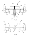
- FIGS. 1 to 5 represent a first embodiment of a wind powered vehicle 10 propelled by the present invention.
- an amphibious sailboat comprising for this purpose a rigid tubular frame 20, for example made of corrosion resistant metal (including saline) such as stainless steel or aluminum.
- the tubular frame 20 comprises a double-bent hollow tube at 90 ° forming two longitudinal lateral tubes 22 and 23 parallel to each other and a rear tube 24.
- the frame also comprises two transverse bars or reinforcing transverse tubes respectively before and 25 intermediate 26, fixed, for example by welding or brazing, to the lateral tubes 22 and 23, parallel to the rear tube 24.
- the rigid tubular frame 20 is about 1875 mm long and about 1150 mm wide.
- the transverse reinforcing tubes 25 and 26 are spaced from each other by 1025 mm and are 1050 mm wide.
- the intermediate reinforcing bar 26 is situated approximately 325 mm from the rear tube 24, and the front reinforcing transverse bar 25 is located approximately 475 mm from the end of the lateral tubes 22 and 23 of the frame 20.
- the frame 20 also includes a mast foot 30 welded to the center of the front transverse bar 25 and making an angle of about 100 ° with the frame (see figure 2 ) to be tilted backwards.
- the mast foot 30 comprises a hollow tube 32 of 70mm diameter and 250 m in length capable of receiving a mast (not shown) of metal such as aluminum, or composite material, said mast supporting a wing type known (not shown), such as a windsurf sail or sailboat made of synthetic material.
- Tensile elements of the sail such as pulleys and ropes (not shown), are also provided for maneuvering the sail yacht according to the wind, as well as on firm ground such as sand, than on the water.
- the mast foot 30 also has a reinforcement 34 in the form of a bent tube welded to both the hollow tube 32 of the mast foot 30 and the front transverse tube 25 (see FIG. figure 4 ).
- the chassis 20 is provided with three wheels distributed, with respect to the usual direction of movement of the tank from the rear to the front, in a rear guide wheel 51 and two front wheels 52 and 53.
- the rear steering wheel 51 is mounted in rotation about an axis 54 on a profiled fork 55 of stainless steel or aluminum, itself pivotally mounted on a rigid plate 56 welded to the center of the rear tube 24.
- the fork 55 is typically about 360 mm in height (see figure 3 ).
- the rear wheel 51 made of aluminum is thin, solid and profiled to act as a rudder once the sand yacht 10 immersed.
- This rear wheel 51 is provided with a tire 57 with air chamber and it measures about 560 mm in diameter and 110 mm thick at its axis of rotation 54.
- the front wheels 52 and 53 are rotated respectively around axes 58 and 59, on either side of the lateral tubes 22 and 23.
- the pins 58 and 59 are located substantially 45 mm from the end of each of said lateral tubes.
- the front wheels 52 and 53 are plastic hub provided with a tube-type air tube tire, and each measure about 400 mm in diameter and 200 mm wide in order to have a good ground resistance, especially in a sporting use.
- the front portion of the frame 20, that is to say close to the end of the side tubes 22 and 23, is located at about 20 cm from the ground
- the chassis 20 of the sailboat 10 of the present invention is inclined relative to the reference plane P defined by the contact of the three wheels with the ground.
- a steering system 60 is provided to cooperate with the rear steering wheel 51.
- a spreader 61 which can be manipulated by the user's feet, is connected directly to the fork 55 of the rear wheel 51 via two cables 62 stretched through rings 63 welded under the reinforcing transverse bars 25 and 26 (see figures 1 , 3 and 4 ).
- the spreader 61 is also slidably mounted on a longitudinal rail 64 so that it can be adjusted according to the length of the legs of the user and / or his position on the sailboat 10.
- This trampoline 80 thus serves as comfortable multi-position seat zone 82 for at least one user, or even two, like a catamaran.
- the dimensions of the trampoline are about 1850 mm long and 800 mm wide.
- buoyancy means 90 are connected to the tubular frame 20. More specifically, two hollow floats 91 and 92 at bottom substantially flat are arranged under the frame 20, partially on either side of the lateral tubes 22 and 23, as is visible in particular on the figures 1 and 3 . These floats 91 and 92 are each constituted by a hollow volume of injection-molded plastic material, by injection inflation, or by rotational molding, such as polyester or a composite material for example based on fiberglass, carbon or kevlar.
- Each float 91 or 92 is attached to a lateral tube 22 or 23 via two pairs 93 and 94 of circular plates welded to the tubular frame 20 at the junction between the side tubes and the transverse reinforcement bars.
- Each plate 93 or 94 is made of stainless steel or aluminum, and has a diameter of about 150 mm and holes 95 for fixing screw passage to the floats 91 and 92.
- the vehicle also has a waterline 96 which is inclined relative to the reference plane P.
- the overall length of the sailplane 10, that is from the axis of the rear wheel 51 to the axis of the front wheels 52 and 53, is about 2200 mm.
- the sailboat 10 of the present invention can pass directly from a position of use on a firm ground, such as for example a paved road or, more frequently, a sandy beach, to a position of use on the water (lake, sea, ocean, river, basin ...), without any manipulation of any kind for the user.
- a firm ground such as for example a paved road or, more frequently, a sandy beach
- the transition from a rolling mode of travel to a floating mode of movement, and vice versa is immediate, and is simply done thanks to the force of the wind blowing in the sail to advance the tank 10.
- the floats 91 and 92 swing gradually by pivoting about themselves about a virtual axis substantially perpendicular to the main direction of elongation of the tank, so that the front wheels 52 and 53 are completely and automatically raised above the water level, as shown on the figure 5 .
- the entry of the sailboat 10 in the water causes a mass displacement towards the center of gravity of the floats which is located towards the rear of the tubular frame 20 because of the particular shape of said floats 91 and 92.
- the front of the tank 10 lifts several centimeters or tens of centimeters so that the water line 96 (illustrated on the figure 2 ) of each float 91 and 92 substantially coincides with the level E of the water and is mainly located below the bottom of the front wheels 52 and 53 to prevent them coming into contact with water.
- the rear wheel 51 thin, solid and connected to the steering system "terrestrial" is located partly below the waterline 96 and serves as a rudder to guide the sand yacht 10 in the water.
- the user can easily navigate the amphibious sand yacht using the rudder 61 in its nautical use.
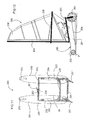
- FIGS. 6 to 10 illustrate a second preferred embodiment of the amphibious sand yacht of the present invention.
- the sand yacht 100 essentially differs from the first embodiment of the Figures 1 to 5 in that it comprises a fully floating frame 120 and a flotation means 190 formed by three floats 191, 192 and 193 molded in one piece of hollow plastic material with said frame 120.
- This solution easier and more quick to implement, also allows to create highly variable shapes while reducing the structure of the vehicle without losing the rigidity characteristic of the chassis.
- a multi-position seating area 182 arranged for example at the rear and in the center of the sailwear 100, is integrally molded to the frame 120. This area receives one or more people according to the dimensions of the tank 100.
- the sand yacht 100 also has an inclined mast foot 130 which is also integrally molded in the frame 120 and which can optionally be reinforced internally by a rigid tube (not shown).
- This mast base can receive the same type of mast and sail as in the previous embodiment.
- the sail-boat 100 has a front steering wheel 151 and two rear wheels 152 and 153.
- the front wheel is placed at the end of the central float 193, and the rear wheels 152 and 153 are integrated under the side floats 191 and 192, at the rear of the tank (see figure 8 ).
- a rudder system (not shown) is also provided to maneuver the steering wheel 151 on firm ground.
- a retractable rudder 155 is also mounted at the rear of the frame 120 to maneuver the sailboat 110 once it in the water.
- the tank also has a water line 196 inclined relative to the reference plane P defined by the three wheels 151, 152 and 153 when in the position of use on firm ground, as illustrated by the figure 7 .
- the sand yacht of the second embodiment is approximately 3000 mm long by 1600 mm wide.
- the frame 120 When the sand yacht 100 leaves the firm ground, for example a sand beach, and advances in the water, the frame 120 gradually tilts backwards due to the effect of the pressure of the water. exerting on the floats 191, 192 and 193, and the particular form thereof. Thus, the front portion of the vehicle is raised to automatically plan the front wheel 151 which then go completely above the level E of the water, as illustrated by the figure 9 .
- the chassis 120 floats and its waterline 196 substantially coincides with the water level E.
- the rudder 155 dives into the water, either automatically due to the tilting of the frame 120, or manually to the using a joint.
- this sand yacht 100 is similar to that of the sailboat 10 of the first embodiment.
- the user is seated in the seat area 182.
- the user rotates the front wheel 151 for example using a rudder (not shown ) while stretching and orienting the sail.
- the user uses the rudder 155 by hand using for example a bar (not shown), always tending and orienting the sail.
- the frame 120 can be port or starboard so that one of the rear wheels 152 or 153 can also be found above the level E of the vehicle. water (see figure 10 ), which further reduces the friction in the water due to the wake. This also allows the user to perform acrobatic tricks without loss of maneuverability, speed or stability of the vehicle. Thus, reducing the wake of the vehicle in the water due to the projection of the front wheel can improve its performance in speed.
- the sailboat 200 comprises a flotation means 290 provided with two elongate hollow floats 291 and 292 connected in parallel with each other via a tubular frame 220 upper stainless steel or aluminum.
- the frame 220 is constituted by two lateral tubes 222 and 223, a rear tube 224, a front tube 225 and an intermediate tube 226, which are firmly fixed to each other, for example by welding, to form a rectangular rectangular frame.
- a trampoline 80 is stretched between the tubes 222, 223, 225 and 226, to form a comfortable seat for the user.
- Two fine rear guide wheels 251 and 251 ', and no longer one, are attached to the rear corners of the tubular frame 220, substantially to the connection between the rear tube 224 and the side tubes 222 and 223. These rear guide wheels 151 and 151 allow the yacht 200 to be steered when it is moved on firm ground or in the water.
- the vehicle 200 In its front part, the vehicle 200 is provided with front wheels 252 and 253 which are non-steered respectively in each of the floats 291 and 292.
- the vehicle 200 thus has four wheels, unlike the two previous embodiments which have only three.
- the vehicle 200 and in particular the floats 291 and 292, has a waterline 296 which is inclined with respect to the reference plane P defined by the contact surfaces of the vehicle wheels when it rests on firm ground (see FIG. figure 12 ).
- the frame 220 is also provided, substantially in the middle of the front tube 225, with a hollow tube forming a foot 230 for receiving the mast 234 of a wing such as a standard sailboard 236, that is to say to say an articulated sail equipped with a wishbone 238.
- a wing such as a standard sailboard 236, that is to say to say an articulated sail equipped with a wishbone 238.
- a rudder 261 actuable by the feet of the user, is hingedly mounted on the front tube 225 of the frame 220.
- the rudder 261 is connected to a cable 262 along the tubes 222, 223, 224 and 225 in a closed loop to controlling the two rear guide wheels 251 and 251 'by means of lateral return control surfaces 263 and 264.
- the sand yachting 200 When the sand yachting 200 circulates on firm ground, such as the sand of a beach, it can roll on its four wheels and be propelled by the force of the wind blowing in the sail 236.
- the manipulation of the rudder 261 makes it possible to turn easily the rear wheels 251 and 251 'to orient the tank.
- the front wheels 252 and 253 of the vehicle 200 are automatically and completely raised above the level of the water E by tilting the floats 291 and 292 undergoing the thrust of the water.
- the front wheels 252 and 253 do not create any wake that can slow the vehicle. Only the two thin profiled rear wheels 151 and 151 'remain immersed and then serve as a rudder when the vehicle is moving in the water thanks to the force of the wind.
- the vehicle typically measures, overall, a length of about 3 m and a width of about 1.50 m.
- the mast and the sail can be replaced by, or collaborate with, another mode of propulsion, such as a mechanical propulsion mode, for example an electric or combustion engine, a liquid air propellant or with hydrogen, or equivalent.
- a mechanical propulsion mode for example an electric or combustion engine, a liquid air propellant or with hydrogen, or equivalent.
- the frame can support an underwater propulsion propeller under the waterline and / or a submarine propeller for water propulsion placed above the waterline, to compensate for the lack of wind or to go faster.
- FIGS. 13 and 14 illustrate a fourth embodiment of the invention materializing in the form of an amphibious motorized vehicle 300 such as a jet ski or a jet ski.
- This vehicle 300 comprises a central rigid chassis 320, for example a tubular chassis of the type of those fitted to certain motorcycles, locally supporting a shroud 315, a seat area 382 and a flotation means 390, for example in the form of a float 391.
- the frame 320 also supports one or two front wheels 351 (s) connected to a handlebar 360 and a rear propulsion wheel 352 connected to a motor (not shown as hidden behind the fairing) combustion type, electric, compressed air, hydrogen or equivalent.
- the vehicle 300 is also a ground scooter that can ride on firm ground such as a road, a dirt road or a sandy beach.
- the rear wheel 352 integrated in the float is solid, sufficiently thin and profiled to minimize its wake in the water, and it also has a significantly larger diameter than that of the front wheel. It can, if necessary, be actuated to form a rudder in the floating position of the vehicle.
- the float 391 has dimensions, in particular width and length, adapted to ensure a stability of the vehicle 300 in its nautical use and a template, especially in width, sufficiently reduced so as not to interfere with road use and meet the standards. force for this type of vehicle.
- the float 391 also has a water line 396 inclined relative to the plane P of contact with the wheels 351 and 352 when the vehicle is in land use mode ( figure 13 ).
- the float 391 tilts backwards and the front of the vehicle rises so that the water line 396 substantially coincides with the surface of the water E ( figure 14 ).
- This tilting movement causes the planing of the front wheel 351 completely above the water so that it does not cause any wakes harmful to the movement of the vehicle in nautical use mode.
- the vehicle 300 also has for this purpose water propulsion means such as an underwater turbine which is either directly linked to the engine of the rear wheel 352 or is independent of it.
- the vehicle 300 may also have an articulated rear rudder which retracts for example in the fairing or in the float in land use.
- the passage of the water to the ground is carried out without modification of the vehicle except to pass from the submarine propulsion to the propulsion of the rear wheel when this one comes in contact with a firm ground.
- a variant would result in a paddle wheel at the rear of the vehicle allowing for single propulsion in water and on the ground.
- the frame can be connected to a kite via hangers, or have several masts / sails side by side.
- the frame can also be closed by a rigid protective shell waterproof, made for example of transparent plastic material. This solution protects the user from bad weather and shocks.
- a crankset can also be connected to the front and / or rear wheels in land use, and possibly to a retractable paddle wheel in nautical use.
- Means for lifting at least one wheel above the water line of sand yachting may also be provided in addition.
- These means may for example comprise an electric piston, hydraulic or pneumatic, or a lever system, cam or gear.
- the number of floats may be greater than two, for example three or four.
- the third float can be placed at the front or rear of the vehicle to increase the floatation of the latter and participate in the elevation of the front wheel.
- the trampoline 80 can be replaced by a flexible and solid fabric stretched between the side and rear tubes of the frame, for example a canvas provided with orifices allowing the flow of water, for example based on nylon or kevlar.
- the rudder steering system can be replaced by a manual direct drive control such as a handle (not shown) engageable with the fork 55.
- the tubular frame Figures 1 to 5 and 11 to 12 can be of one piece, made of metal by foundry or composite material.
- sand yachts The dimensions of sand yachts are given for information only illustrating the described embodiments. Thus, it can measure between 1500 and 4000 mm in length and between 1000 and 2500 mm in width.
- the present invention is also adapted to the field of recreational vehicles such as amphibious cars sedans or convertibles, in the field of military vehicles such as intervention vehicles possibly off-road, or in the field of vehicles of the maritime police or firefighters such as inflatable boats.
- vehicle of the present invention will comply with the standards in force, especially in terms of occupant safety, signaling, comfort or pollution.
Claims (27)
- Rollfahrzeug (10; 100; 200; 300), welches durch Windkraft oder dergleichen angetrieben ist, umfassend wenigstens:- ein starres Fahrgestell (20; 120; 220; 320),- wenigstens zwei Räder (51, 52, 53; 151, 152, 153; 251, 251', 252, 253, 351, 352),- ein Lenksystem (60; 360),- ein Auftriebsmittel (90; 190; 290; 390), welches die Unsinkbarkeit des Fahrzeugs (10; 100; 200; 300) sicherstellt, wenn dieses in Wasser eintaucht,wobei die Kontaktflächen der Räder (51, 52, 53; 151, 152, 153; 251, 251', 252, 253; 351, 352) auf einem geschlossenen Boden ruhen, welcher eine Bezugsebene (P) definiert, dadurch gekennzeichnet, dass das Auftriebsmittel (90; 190; 290; 390) eine Wasserlinie (96; 196; 296; 396) aufweist, welche im Verhältnis zu dieser Ebene (P) derart geneigt ist, dass sobald das Fahrzeug (10; 100; 200; 300) eintaucht, wenigstens ein Rad (52, 53; 151; 252, 253; 351) durch Wirkung des Drucks, welcher durch das Wasser auf das Auftriebsmittel (90; 190; 290; 390) ausgeübt wird, aus dem Wasser hochgetrieben wird.
- Fahrzeug nach Anspruch 1, wobei das Auftriebsmittel (90; 190; 290; 390) wenigstens einen Schwimmer (91; 92; 191; 192; 193; 292, 293, 391) umfasst, welcher mit dem Fahrgestell (20; 120; 220; 320) verbunden oder darin integriert ist und die Wasserlinie (96; 196; 296; 396) aufweist.
- Fahrzeug nach Anspruch 2, wobei die Räder (51, 52, 53; 151, 151', 152, 153) mit Bezug auf die normale Bewegungsrichtung des Fahrzeugs nach vorne aufgeteilt sind in wenigstens ein hinteres Lenkrad (51; 251, 251'), welches mit dem Lenksystem (60) verbunden ist, und zwei vordere Räder (52, 53; 252, 253), wobei die vorderen Räder (52, 53; 252, 253) vollständig aus dem Wasser hochgetrieben sind, wenn das Fahrzeug (10; 200) eingetaucht ist.
- Fahrzeug nach Anspruch 3, wobei jedes hintere Rad (51; 251, 251') vollflächig ist, um in der Schwimmposition des Fahrzeugs (10; 200) ein Ruder zu bilden, und ausreichend fein und profiliert ist, um seine Wirbelbildung im Wasser zu minimieren.
- Fahrzeug nach Anspruch 3 oder 4, wobei das Auftriebsmittel (90; 290) zwei hohle longitudinale Schwimmkörper (91, 92; 291, 292) umfasst, welche unter dem Fahrgestell (20; 220) angeordnet sind.
- Fahrzeug nach einem der Ansprüche 3-5, wobei das Fahrgestell (20; 220) röhrenartig ist und longitudinale seitliche Rohre (22, 23; 222, 223), ein hinteres Rohr (24, 224), ein vorderes Rohr (25; 225) und ein Zwischenrohr (26; 226) umfasst, so dass ein im Wesentlichen rechtwinkliger Rahmen gebildet wird.
- Fahrzeug nach Anspruch 6, wobei ein Trampolin (80) zwischen den Rohren (22, 23, 25, 26; 222, 223, 225, 226) des röhrenartigen Fahrgestells (20; 220) gehalten ist, um einen Mehrpositionssitz (82) zu bilden.
- Fahrzeug nach Anspruch 6 oder 7, wobei das Lenksystem (60) einen Steuerknüppel (261) umfasst, welcher mit einem zu einer Schleife geschlossenen Kabel (262) verbunden ist, welches an den Rohren (222, 223, 224, 225) des Fahrgestells entlangläuft und auf die hinteren Räder (251, 251') einwirkt.
- Fahrzeug nach Anspruch 8, dadurch gekennzeichnet, dass es zwei hintere Lenkräder (251, 251'), welche mit Hilfe des Kabels (262) kinematisch miteinander verbunden sind, und zwei vordere Räder (252, 253) umfasst.
- Fahrzeug nach einem der Ansprüche 3-9, wobei die vorderen Räder (252, 253) in dem Auftriebsmittel (290) integriert sind.
- Fahrzeug nach einem der Ansprüche 3-7, wobei das Lenksystem (60) einen Steuerknüppel (61) umfasst, welcher entlang einer Schiene (64) einstellbar ist und über Kabel (62), welche durch Ringe (63) verlaufend gehalten sind, mit einer Gabel (55) des hinteren Rads (51) verbunden ist.
- Fahrzeug nach Anspruch 1 oder 2, wobei die Räder (151, 152, 153; 351, 352) mit Bezug auf die normale Bewegungsrichtung des Fahrzeugs nach vorne aufgeteilt sind in ein vorderes Lenkrad (151) und wenigstens ein hinteres Rad (152, 153; 352), wobei das vordere Rad (151, 351) vollständig aus dem Wasser hochgetrieben ist, wenn das Fahrzeug (100) eingetaucht ist.
- Fahrzeug nach Anspruch 12, wobei das Auftriebsmittel (190) und das Fahrgestell (120) ein einziges hohles Teil bilden.
- Fahrzeug nach Anspruch 13, wobei ein Mehrpositionssitz (182) in dem Fahrgestell (120) integriert ist, insbesondere durch Formguss.
- Fahrzeug nach einem der Ansprüche 12-14, wobei das Hinterteil des Fahrgestells (120) mit einem Ruder (155) versehen ist, welches einziehbar im Wesentlichen zwischen den hinteren Rädern (152, 153) angeordnet ist.
- Fahrzeug nach einem der Ansprüche 12-15, wobei die hinteren Räder (152, 153) in dem Fahrgestell (120) und/oder dem Auftriebsmittel (190) integriert sind.
- Fahrzeug nach Anspruch 12, dadurch gekennzeichnet, dass es wenigstens ein vorderes Rad (351), welches mit einem Lenker (360) verbunden ist, ein hinteres Antriebsrad (352), einen Sattel (382) und eine Verkleidung (315) umfasst, so dass das Fahrzeug einen Amphibienscooter bildet, welcher in einen Seescooter oder einen Jetski transformierbar ist.
- Fahrzeug nach einem der vorhergehenden Ansprüche, wobei das Auftriebsmittel (90; 190; 290; 390) und/oder das Fahrgestell (20; 120; 220; 320) aus einem formbaren Kunststoffmaterial, insbesondere aus einem Verbundmaterial, realisiert ist/sind.
- Fahrzeug nach einem der vorhergehenden Ansprüche, dadurch gekennzeichnet, dass es außerdem wenigstens ein mechanisches Antriebsmittel umfasst.
- Fahrzeug nach Anspruch 19, wobei das mechanische Antriebsmittel eine Unterwasserschraube oder ein mit einem Motor verbundenes Schaufelrad ist.
- Fahrzeug nach Anspruch 19 oder 20, wobei das mechanische Antriebsmittel eine mit einem Motor verbundene Unterwasserschraube ist.
- Fahrzeug nach einem der vorhergehenden Ansprüche, dadurch gekennzeichnet, dass es außerdem eine Tretkurbel oder einen Motor umfasst, welche bzw. welcher mit wenigstens einem Rad zum Antrieb des Fahrzeugs auf der Erde und/oder im Wasser verbunden ist.
- Fahrzeug nach einem der vorhergehenden Ansprüche, dadurch gekennzeichnet, dass es außerdem Fangleinen und einen Antriebsdrachen umfasst.
- Fahrzeug nach einem der vorhergehenden Ansprüche, wobei das Fahrgestell (120) durch eine wasserdichte Schutzschale geschlossen ist, welche insbesondere aus einem transparenten Kunststoffmaterial realisiert ist.
- Fahrzeug nach einem der vorhergehenden Ansprüche, wobei das Fahrgestell und/oder das Auftriebsmittel wenigstens ein Stabilisatorschwert aufweist/aufweisen.
- Fahrzeug nach einem der vorhergehenden Ansprüche, dadurch gekennzeichnet, dass es außerdem einen Mastfuß (30; 130; 230) umfasst, welcher dazu bestimmt ist, einen Mast (234) aufzunehmen, welcher ein Segel (236) trägt.
- Fahrzeug nach Anspruch 26, dadurch gekennzeichnet, dass der Mastfuß (30; 130; 230) den Mast (234) eines mit einem Wishbone (238) ausgestatteten Standard-Windsurfsegels (236) aufnimmt.
Applications Claiming Priority (2)
| Application Number | Priority Date | Filing Date | Title |
|---|---|---|---|
| FR0410056A FR2875438B1 (fr) | 2004-09-23 | 2004-09-23 | Vehicule amphibie propulse par la force du vent, muni de roues et d'un moyen de flottaison |
| PCT/FR2005/002350 WO2006032791A2 (fr) | 2004-09-23 | 2005-09-22 | Vehicule amphibie propulse par la force du vent ou autre, muni de roues et d'un moyen de flottaison. |
Publications (2)
| Publication Number | Publication Date |
|---|---|
| EP1809525A2 EP1809525A2 (de) | 2007-07-25 |
| EP1809525B1 true EP1809525B1 (de) | 2010-07-28 |
Family
ID=34949670
Family Applications (1)
| Application Number | Title | Priority Date | Filing Date |
|---|---|---|---|
| EP05802665A Not-in-force EP1809525B1 (de) | 2004-09-23 | 2005-09-22 | Durch wind oder eine andere kraft angetriebenes amphibienfahrzeug, das mit rädern und einem flotationsmittel ausgestattet ist |
Country Status (5)
| Country | Link |
|---|---|
| EP (1) | EP1809525B1 (de) |
| AT (1) | ATE475575T1 (de) |
| DE (1) | DE602005022606D1 (de) |
| FR (1) | FR2875438B1 (de) |
| WO (1) | WO2006032791A2 (de) |
Families Citing this family (1)
| Publication number | Priority date | Publication date | Assignee | Title |
|---|---|---|---|---|
| CN201164161Y (zh) * | 2008-01-11 | 2008-12-17 | 深圳市金福娃智能科技有限公司 | 五栖运动魔方旅行箱 |
Family Cites Families (11)
| Publication number | Priority date | Publication date | Assignee | Title |
|---|---|---|---|---|
| CH97187A (de) * | 1921-06-16 | 1922-12-16 | Schneibel Paul | Land- und Wasserautomobil. |
| FR911806A (fr) * | 1945-06-25 | 1946-07-22 | Véhicule à transformation | |
| US3395664A (en) * | 1966-09-12 | 1968-08-06 | Greenberg Lewis Anthony | Tetrahedron sailing vehicle |
| GB1288779A (de) * | 1969-10-25 | 1972-09-13 | ||
| US3895597A (en) * | 1974-05-08 | 1975-07-22 | Lawrence Peska Ass Inc | Wind operated amphibious vehicle |
| US4387661A (en) * | 1980-01-03 | 1983-06-14 | Duff Kenneth R | Amphibious motor-driven cycle |
| FR2537508A1 (fr) * | 1982-12-14 | 1984-06-15 | Collin Christian | Char a voile amphibie |
| GR851800B (de) * | 1984-08-13 | 1985-11-26 | Chauveau Jean Claude | |
| US4838194A (en) * | 1987-12-02 | 1989-06-13 | Williamson Roger L | Amphibious vehicle having an efficient water-borne operational mode |
| GB2293581B (en) * | 1994-12-09 | 1998-12-09 | Robert James Paul Orme | Leisure vehicle for use on land, water or snow |
| US5832862A (en) * | 1997-08-28 | 1998-11-10 | Hulten; Richard E. | Amphibious vehicle |
-
2004
- 2004-09-23 FR FR0410056A patent/FR2875438B1/fr not_active Expired - Fee Related
-
2005
- 2005-09-22 AT AT05802665T patent/ATE475575T1/de not_active IP Right Cessation
- 2005-09-22 DE DE602005022606T patent/DE602005022606D1/de active Active
- 2005-09-22 EP EP05802665A patent/EP1809525B1/de not_active Not-in-force
- 2005-09-22 WO PCT/FR2005/002350 patent/WO2006032791A2/fr active Application Filing
Also Published As
| Publication number | Publication date |
|---|---|
| DE602005022606D1 (de) | 2010-09-09 |
| WO2006032791A2 (fr) | 2006-03-30 |
| FR2875438B1 (fr) | 2008-02-22 |
| ATE475575T1 (de) | 2010-08-15 |
| EP1809525A2 (de) | 2007-07-25 |
| WO2006032791A3 (fr) | 2007-08-02 |
| FR2875438A1 (fr) | 2006-03-24 |
Similar Documents
| Publication | Publication Date | Title |
|---|---|---|
| WO1980000146A1 (fr) | Vehicule transformable pour usages multiples notamment pour pratiquer differents sports et loisirs | |
| US6309263B1 (en) | Bicycle-type marine vessel | |
| WO2009144400A2 (fr) | Engin nautique, destiné à être utilisé par une personne en position debout | |
| FR2854864A1 (fr) | Embarcation nautique a voile | |
| FR2538772A1 (fr) | Navire a voile a hydropteres | |
| EP1809525B1 (de) | Durch wind oder eine andere kraft angetriebenes amphibienfahrzeug, das mit rädern und einem flotationsmittel ausgestattet ist | |
| EP0306388B1 (de) | Modulares Wasserfahrzeug mit drehenden Schwimmern | |
| FR3103780A1 (fr) | Engin nautique gonflable à motorisation électrique destiné à être piloté en position debout | |
| FR2574747A1 (fr) | Engin nautique motorise | |
| FR2725951A1 (fr) | Bateau a voile multicoque a flotteurs plats | |
| EP2864189A1 (de) | Freizeitsegelboot | |
| FR2637562A1 (fr) | Greement mobile pour un engin a voile, et engin a voile pourvu d'un tel greement | |
| CH591358A5 (en) | Light hydrofoil water craft - has front and rear skis and one piece hull and saddle | |
| FR2518047A1 (fr) | Perfectionnements a un engin nautique leger tel qu'une planche a voile permettant sa propulsion mecanique autonome | |
| AU700280B2 (en) | Amphibious sailing craft | |
| FR2549005A1 (fr) | Engin nautique a moteur | |
| FR3039498A1 (fr) | Agencement d'un catamaran de loisir, a voiles, demontable, avec un poste de conduite face a la direction de deplacement | |
| EP2042424B1 (de) | Hybrides Wassersportgerät bestehend aus Surfbrett/Sport-Schwertboot, das mit einem Abspannmast ausgestattet ist, der gleichzeitig in der Quer- und in der Längsebene geneigt werden kann | |
| WO2005108201A1 (fr) | Embarcation non motorisee propulsee par une turbine a pedales | |
| FR3069227B1 (fr) | Vehicule nautique de loisir et de competition a coques et mature inclinables | |
| FR2467773A1 (fr) | Embarcation de plaisance a voile orientable au moyen d'un volant | |
| WO1988007453A1 (fr) | Nacelle utilisee comme element de base pour un engin de deplacement, pouvant etre associee a d'autres elements, permettant quatre modes de deplacement | |
| WO2009009823A1 (en) | Watercraft | |
| FR2625473A1 (fr) | Embarcation du type a propulsion velique derivee, notamment, d'une planche a voile | |
| EP0396591A1 (de) | Schwimmer eines katamaranförmigen surfbrettes, das ausserdem wie ein segelboot verwendbar ist |
Legal Events
| Date | Code | Title | Description |
|---|---|---|---|
| PUAI | Public reference made under article 153(3) epc to a published international application that has entered the european phase |
Free format text: ORIGINAL CODE: 0009012 |
|
| 17P | Request for examination filed |
Effective date: 20070418 |
|
| AK | Designated contracting states |
Kind code of ref document: A2 Designated state(s): AT BE BG CH CY CZ DE DK EE ES FI FR GB GR HU IE IS IT LI LT LU LV MC NL PL PT RO SE SI SK TR |
|
| AX | Request for extension of the european patent |
Extension state: AL BA HR MK YU |
|
| R17D | Deferred search report published (corrected) |
Effective date: 20070802 |
|
| DAX | Request for extension of the european patent (deleted) | ||
| GRAP | Despatch of communication of intention to grant a patent |
Free format text: ORIGINAL CODE: EPIDOSNIGR1 |
|
| GRAS | Grant fee paid |
Free format text: ORIGINAL CODE: EPIDOSNIGR3 |
|
| GRAA | (expected) grant |
Free format text: ORIGINAL CODE: 0009210 |
|
| AK | Designated contracting states |
Kind code of ref document: B1 Designated state(s): AT BE BG CH CY CZ DE DK EE ES FI FR GB GR HU IE IS IT LI LT LU LV MC NL PL PT RO SE SI SK TR |
|
| REG | Reference to a national code |
Ref country code: GB Ref legal event code: FG4D Free format text: NOT ENGLISH |
|
| REG | Reference to a national code |
Ref country code: CH Ref legal event code: EP |
|
| REG | Reference to a national code |
Ref country code: IE Ref legal event code: FG4D Free format text: LANGUAGE OF EP DOCUMENT: FRENCH |
|
| REF | Corresponds to: |
Ref document number: 602005022606 Country of ref document: DE Date of ref document: 20100909 Kind code of ref document: P |
|
| REG | Reference to a national code |
Ref country code: NL Ref legal event code: VDEP Effective date: 20100728 |
|
| PGFP | Annual fee paid to national office [announced via postgrant information from national office to epo] |
Ref country code: FR Payment date: 20101005 Year of fee payment: 6 |
|
| LTIE | Lt: invalidation of european patent or patent extension |
Effective date: 20100728 |
|
| PGFP | Annual fee paid to national office [announced via postgrant information from national office to epo] |
Ref country code: GB Payment date: 20100929 Year of fee payment: 6 |
|
| PG25 | Lapsed in a contracting state [announced via postgrant information from national office to epo] |
Ref country code: FI Free format text: LAPSE BECAUSE OF FAILURE TO SUBMIT A TRANSLATION OF THE DESCRIPTION OR TO PAY THE FEE WITHIN THE PRESCRIBED TIME-LIMIT Effective date: 20100728 Ref country code: LT Free format text: LAPSE BECAUSE OF FAILURE TO SUBMIT A TRANSLATION OF THE DESCRIPTION OR TO PAY THE FEE WITHIN THE PRESCRIBED TIME-LIMIT Effective date: 20100728 Ref country code: NL Free format text: LAPSE BECAUSE OF FAILURE TO SUBMIT A TRANSLATION OF THE DESCRIPTION OR TO PAY THE FEE WITHIN THE PRESCRIBED TIME-LIMIT Effective date: 20100728 Ref country code: AT Free format text: LAPSE BECAUSE OF FAILURE TO SUBMIT A TRANSLATION OF THE DESCRIPTION OR TO PAY THE FEE WITHIN THE PRESCRIBED TIME-LIMIT Effective date: 20100728 |
|
| PG25 | Lapsed in a contracting state [announced via postgrant information from national office to epo] |
Ref country code: IS Free format text: LAPSE BECAUSE OF FAILURE TO SUBMIT A TRANSLATION OF THE DESCRIPTION OR TO PAY THE FEE WITHIN THE PRESCRIBED TIME-LIMIT Effective date: 20101128 Ref country code: SI Free format text: LAPSE BECAUSE OF FAILURE TO SUBMIT A TRANSLATION OF THE DESCRIPTION OR TO PAY THE FEE WITHIN THE PRESCRIBED TIME-LIMIT Effective date: 20100728 Ref country code: PL Free format text: LAPSE BECAUSE OF FAILURE TO SUBMIT A TRANSLATION OF THE DESCRIPTION OR TO PAY THE FEE WITHIN THE PRESCRIBED TIME-LIMIT Effective date: 20100728 Ref country code: CY Free format text: LAPSE BECAUSE OF FAILURE TO SUBMIT A TRANSLATION OF THE DESCRIPTION OR TO PAY THE FEE WITHIN THE PRESCRIBED TIME-LIMIT Effective date: 20100728 Ref country code: BG Free format text: LAPSE BECAUSE OF FAILURE TO SUBMIT A TRANSLATION OF THE DESCRIPTION OR TO PAY THE FEE WITHIN THE PRESCRIBED TIME-LIMIT Effective date: 20101028 |
|
| PGFP | Annual fee paid to national office [announced via postgrant information from national office to epo] |
Ref country code: BE Payment date: 20100927 Year of fee payment: 6 Ref country code: DE Payment date: 20100927 Year of fee payment: 6 |
|
| REG | Reference to a national code |
Ref country code: IE Ref legal event code: FD4D |
|
| PG25 | Lapsed in a contracting state [announced via postgrant information from national office to epo] |
Ref country code: LV Free format text: LAPSE BECAUSE OF FAILURE TO SUBMIT A TRANSLATION OF THE DESCRIPTION OR TO PAY THE FEE WITHIN THE PRESCRIBED TIME-LIMIT Effective date: 20100728 Ref country code: SE Free format text: LAPSE BECAUSE OF FAILURE TO SUBMIT A TRANSLATION OF THE DESCRIPTION OR TO PAY THE FEE WITHIN THE PRESCRIBED TIME-LIMIT Effective date: 20100728 Ref country code: GR Free format text: LAPSE BECAUSE OF FAILURE TO SUBMIT A TRANSLATION OF THE DESCRIPTION OR TO PAY THE FEE WITHIN THE PRESCRIBED TIME-LIMIT Effective date: 20101029 |
|
| PG25 | Lapsed in a contracting state [announced via postgrant information from national office to epo] |
Ref country code: DK Free format text: LAPSE BECAUSE OF FAILURE TO SUBMIT A TRANSLATION OF THE DESCRIPTION OR TO PAY THE FEE WITHIN THE PRESCRIBED TIME-LIMIT Effective date: 20100728 Ref country code: IE Free format text: LAPSE BECAUSE OF FAILURE TO SUBMIT A TRANSLATION OF THE DESCRIPTION OR TO PAY THE FEE WITHIN THE PRESCRIBED TIME-LIMIT Effective date: 20100728 Ref country code: MC Free format text: LAPSE BECAUSE OF NON-PAYMENT OF DUE FEES Effective date: 20100930 |
|
| REG | Reference to a national code |
Ref country code: CH Ref legal event code: PL |
|
| PG25 | Lapsed in a contracting state [announced via postgrant information from national office to epo] |
Ref country code: IT Free format text: LAPSE BECAUSE OF FAILURE TO SUBMIT A TRANSLATION OF THE DESCRIPTION OR TO PAY THE FEE WITHIN THE PRESCRIBED TIME-LIMIT Effective date: 20100728 Ref country code: SK Free format text: LAPSE BECAUSE OF FAILURE TO SUBMIT A TRANSLATION OF THE DESCRIPTION OR TO PAY THE FEE WITHIN THE PRESCRIBED TIME-LIMIT Effective date: 20100728 Ref country code: CZ Free format text: LAPSE BECAUSE OF FAILURE TO SUBMIT A TRANSLATION OF THE DESCRIPTION OR TO PAY THE FEE WITHIN THE PRESCRIBED TIME-LIMIT Effective date: 20100728 Ref country code: EE Free format text: LAPSE BECAUSE OF FAILURE TO SUBMIT A TRANSLATION OF THE DESCRIPTION OR TO PAY THE FEE WITHIN THE PRESCRIBED TIME-LIMIT Effective date: 20100728 Ref country code: RO Free format text: LAPSE BECAUSE OF FAILURE TO SUBMIT A TRANSLATION OF THE DESCRIPTION OR TO PAY THE FEE WITHIN THE PRESCRIBED TIME-LIMIT Effective date: 20100728 |
|
| PLBE | No opposition filed within time limit |
Free format text: ORIGINAL CODE: 0009261 |
|
| STAA | Information on the status of an ep patent application or granted ep patent |
Free format text: STATUS: NO OPPOSITION FILED WITHIN TIME LIMIT |
|
| PG25 | Lapsed in a contracting state [announced via postgrant information from national office to epo] |
Ref country code: ES Free format text: LAPSE BECAUSE OF FAILURE TO SUBMIT A TRANSLATION OF THE DESCRIPTION OR TO PAY THE FEE WITHIN THE PRESCRIBED TIME-LIMIT Effective date: 20101108 |
|
| 26N | No opposition filed |
Effective date: 20110429 |
|
| PG25 | Lapsed in a contracting state [announced via postgrant information from national office to epo] |
Ref country code: LI Free format text: LAPSE BECAUSE OF NON-PAYMENT OF DUE FEES Effective date: 20100930 Ref country code: CH Free format text: LAPSE BECAUSE OF NON-PAYMENT OF DUE FEES Effective date: 20100930 |
|
| REG | Reference to a national code |
Ref country code: FR Ref legal event code: CA |
|
| REG | Reference to a national code |
Ref country code: DE Ref legal event code: R097 Ref document number: 602005022606 Country of ref document: DE Effective date: 20110429 |
|
| BERE | Be: lapsed |
Owner name: LOD Effective date: 20110930 |
|
| GBPC | Gb: european patent ceased through non-payment of renewal fee |
Effective date: 20110922 |
|
| REG | Reference to a national code |
Ref country code: FR Ref legal event code: ST Effective date: 20120531 |
|
| PG25 | Lapsed in a contracting state [announced via postgrant information from national office to epo] |
Ref country code: BE Free format text: LAPSE BECAUSE OF NON-PAYMENT OF DUE FEES Effective date: 20110930 |
|
| REG | Reference to a national code |
Ref country code: DE Ref legal event code: R119 Ref document number: 602005022606 Country of ref document: DE Effective date: 20120403 |
|
| PG25 | Lapsed in a contracting state [announced via postgrant information from national office to epo] |
Ref country code: DE Free format text: LAPSE BECAUSE OF NON-PAYMENT OF DUE FEES Effective date: 20120403 |
|
| PG25 | Lapsed in a contracting state [announced via postgrant information from national office to epo] |
Ref country code: FR Free format text: LAPSE BECAUSE OF NON-PAYMENT OF DUE FEES Effective date: 20110930 Ref country code: GB Free format text: LAPSE BECAUSE OF NON-PAYMENT OF DUE FEES Effective date: 20110922 |
|
| PG25 | Lapsed in a contracting state [announced via postgrant information from national office to epo] |
Ref country code: LU Free format text: LAPSE BECAUSE OF NON-PAYMENT OF DUE FEES Effective date: 20100922 Ref country code: HU Free format text: LAPSE BECAUSE OF FAILURE TO SUBMIT A TRANSLATION OF THE DESCRIPTION OR TO PAY THE FEE WITHIN THE PRESCRIBED TIME-LIMIT Effective date: 20110129 |
|
| PG25 | Lapsed in a contracting state [announced via postgrant information from national office to epo] |
Ref country code: TR Free format text: LAPSE BECAUSE OF FAILURE TO SUBMIT A TRANSLATION OF THE DESCRIPTION OR TO PAY THE FEE WITHIN THE PRESCRIBED TIME-LIMIT Effective date: 20100728 |
|
| PG25 | Lapsed in a contracting state [announced via postgrant information from national office to epo] |
Ref country code: PT Free format text: LAPSE BECAUSE OF NON-PAYMENT OF DUE FEES Effective date: 20100728 |