EP1807101B1 - Devices and methods for integrated continuous manufacturing of biological molecules - Google Patents
Devices and methods for integrated continuous manufacturing of biological molecules Download PDFInfo
- Publication number
- EP1807101B1 EP1807101B1 EP05800224.7A EP05800224A EP1807101B1 EP 1807101 B1 EP1807101 B1 EP 1807101B1 EP 05800224 A EP05800224 A EP 05800224A EP 1807101 B1 EP1807101 B1 EP 1807101B1
- Authority
- EP
- European Patent Office
- Prior art keywords
- continuous
- tissue culture
- culture fluid
- flow rate
- protein
- Prior art date
- Legal status (The legal status is an assumption and is not a legal conclusion. Google has not performed a legal analysis and makes no representation as to the accuracy of the status listed.)
- Active
Links
- 238000000034 method Methods 0.000 title claims description 128
- 238000004519 manufacturing process Methods 0.000 title description 13
- 230000008569 process Effects 0.000 claims description 90
- 239000000047 product Substances 0.000 claims description 77
- 230000010412 perfusion Effects 0.000 claims description 73
- 238000000855 fermentation Methods 0.000 claims description 71
- 230000004151 fermentation Effects 0.000 claims description 71
- 102000004169 proteins and genes Human genes 0.000 claims description 70
- 108090000623 proteins and genes Proteins 0.000 claims description 70
- 239000002245 particle Substances 0.000 claims description 64
- 239000012531 culture fluid Substances 0.000 claims description 62
- 238000000108 ultra-filtration Methods 0.000 claims description 62
- 239000012528 membrane Substances 0.000 claims description 52
- 238000000746 purification Methods 0.000 claims description 48
- 239000000203 mixture Substances 0.000 claims description 44
- 239000012465 retentate Substances 0.000 claims description 24
- 239000000356 contaminant Substances 0.000 claims description 10
- 238000003306 harvesting Methods 0.000 description 37
- 238000001914 filtration Methods 0.000 description 25
- 238000002955 isolation Methods 0.000 description 23
- 239000012466 permeate Substances 0.000 description 21
- 239000000872 buffer Substances 0.000 description 20
- 230000004907 flux Effects 0.000 description 20
- 238000002336 sorption--desorption measurement Methods 0.000 description 20
- 210000004027 cell Anatomy 0.000 description 17
- 239000012530 fluid Substances 0.000 description 17
- 238000011068 loading method Methods 0.000 description 16
- 101000911390 Homo sapiens Coagulation factor VIII Proteins 0.000 description 15
- 238000000926 separation method Methods 0.000 description 13
- 239000000243 solution Substances 0.000 description 13
- 238000012546 transfer Methods 0.000 description 13
- 102100026735 Coagulation factor VIII Human genes 0.000 description 12
- 239000002775 capsule Substances 0.000 description 11
- 239000000463 material Substances 0.000 description 11
- 238000010923 batch production Methods 0.000 description 10
- 238000012545 processing Methods 0.000 description 10
- 238000010924 continuous production Methods 0.000 description 9
- 238000013461 design Methods 0.000 description 9
- 230000036512 infertility Effects 0.000 description 9
- 230000007774 longterm Effects 0.000 description 9
- 239000012264 purified product Substances 0.000 description 9
- 238000004587 chromatography analysis Methods 0.000 description 8
- 238000004140 cleaning Methods 0.000 description 8
- 230000002572 peristaltic effect Effects 0.000 description 8
- 230000007704 transition Effects 0.000 description 8
- 230000008901 benefit Effects 0.000 description 7
- 230000002829 reductive effect Effects 0.000 description 7
- 238000001179 sorption measurement Methods 0.000 description 7
- 229910001220 stainless steel Inorganic materials 0.000 description 7
- 239000010935 stainless steel Substances 0.000 description 7
- 230000001419 dependent effect Effects 0.000 description 6
- 239000000706 filtrate Substances 0.000 description 6
- 239000005090 green fluorescent protein Substances 0.000 description 6
- 239000011159 matrix material Substances 0.000 description 6
- 108010054218 Factor VIII Proteins 0.000 description 5
- 102000001690 Factor VIII Human genes 0.000 description 5
- 230000000712 assembly Effects 0.000 description 5
- 238000000429 assembly Methods 0.000 description 5
- 230000009286 beneficial effect Effects 0.000 description 5
- 238000004113 cell culture Methods 0.000 description 5
- 239000003085 diluting agent Substances 0.000 description 5
- 230000000694 effects Effects 0.000 description 5
- 239000008241 heterogeneous mixture Substances 0.000 description 5
- 238000002156 mixing Methods 0.000 description 5
- 238000011107 packed bed chromatography Methods 0.000 description 5
- 230000010287 polarization Effects 0.000 description 5
- 230000008929 regeneration Effects 0.000 description 5
- 238000011069 regeneration method Methods 0.000 description 5
- 230000000717 retained effect Effects 0.000 description 5
- XLYOFNOQVPJJNP-UHFFFAOYSA-N water Substances O XLYOFNOQVPJJNP-UHFFFAOYSA-N 0.000 description 5
- 239000012141 concentrate Substances 0.000 description 4
- 238000010828 elution Methods 0.000 description 4
- 239000000758 substrate Substances 0.000 description 4
- 108010043121 Green Fluorescent Proteins Proteins 0.000 description 3
- 102000004144 Green Fluorescent Proteins Human genes 0.000 description 3
- HEMHJVSKTPXQMS-UHFFFAOYSA-M Sodium hydroxide Chemical compound [OH-].[Na+] HEMHJVSKTPXQMS-UHFFFAOYSA-M 0.000 description 3
- 238000003556 assay Methods 0.000 description 3
- 230000015572 biosynthetic process Effects 0.000 description 3
- 230000015556 catabolic process Effects 0.000 description 3
- 238000006731 degradation reaction Methods 0.000 description 3
- 229920002521 macromolecule Polymers 0.000 description 3
- 238000011045 prefiltration Methods 0.000 description 3
- 102000004196 processed proteins & peptides Human genes 0.000 description 3
- 108090000765 processed proteins & peptides Proteins 0.000 description 3
- 239000011347 resin Substances 0.000 description 3
- 229920005989 resin Polymers 0.000 description 3
- 238000005070 sampling Methods 0.000 description 3
- 239000003381 stabilizer Substances 0.000 description 3
- 238000010025 steaming Methods 0.000 description 3
- 238000011146 sterile filtration Methods 0.000 description 3
- 238000011144 upstream manufacturing Methods 0.000 description 3
- 102000004506 Blood Proteins Human genes 0.000 description 2
- 108010017384 Blood Proteins Proteins 0.000 description 2
- 239000004695 Polyether sulfone Substances 0.000 description 2
- 238000010364 biochemical engineering Methods 0.000 description 2
- 238000005352 clarification Methods 0.000 description 2
- 150000001875 compounds Chemical class 0.000 description 2
- 230000003750 conditioning effect Effects 0.000 description 2
- 238000003795 desorption Methods 0.000 description 2
- 230000001627 detrimental effect Effects 0.000 description 2
- 238000009826 distribution Methods 0.000 description 2
- 239000002158 endotoxin Substances 0.000 description 2
- 238000002474 experimental method Methods 0.000 description 2
- 238000012432 intermediate storage Methods 0.000 description 2
- 230000014759 maintenance of location Effects 0.000 description 2
- 238000011140 membrane chromatography Methods 0.000 description 2
- 238000005374 membrane filtration Methods 0.000 description 2
- 238000001471 micro-filtration Methods 0.000 description 2
- 230000000813 microbial effect Effects 0.000 description 2
- 244000005700 microbiome Species 0.000 description 2
- 229920006393 polyether sulfone Polymers 0.000 description 2
- 229920001184 polypeptide Polymers 0.000 description 2
- 229940124272 protein stabilizer Drugs 0.000 description 2
- 238000005086 pumping Methods 0.000 description 2
- 238000011084 recovery Methods 0.000 description 2
- 230000009467 reduction Effects 0.000 description 2
- 238000002415 sodium dodecyl sulfate polyacrylamide gel electrophoresis Methods 0.000 description 2
- 241000894007 species Species 0.000 description 2
- 238000012027 sterile manufacturing Methods 0.000 description 2
- 230000001954 sterilising effect Effects 0.000 description 2
- 238000004659 sterilization and disinfection Methods 0.000 description 2
- 238000012360 testing method Methods 0.000 description 2
- 238000010200 validation analysis Methods 0.000 description 2
- 239000002699 waste material Substances 0.000 description 2
- 239000008215 water for injection Substances 0.000 description 2
- 241000894006 Bacteria Species 0.000 description 1
- 102000015081 Blood Coagulation Factors Human genes 0.000 description 1
- 108010039209 Blood Coagulation Factors Proteins 0.000 description 1
- 102100022641 Coagulation factor IX Human genes 0.000 description 1
- 102100023804 Coagulation factor VII Human genes 0.000 description 1
- 108010076282 Factor IX Proteins 0.000 description 1
- 108010023321 Factor VII Proteins 0.000 description 1
- 108010014173 Factor X Proteins 0.000 description 1
- 241000233866 Fungi Species 0.000 description 1
- 102000003886 Glycoproteins Human genes 0.000 description 1
- 108090000288 Glycoproteins Proteins 0.000 description 1
- 102000008394 Immunoglobulin Fragments Human genes 0.000 description 1
- 108010021625 Immunoglobulin Fragments Proteins 0.000 description 1
- 102000000588 Interleukin-2 Human genes 0.000 description 1
- 108010002350 Interleukin-2 Proteins 0.000 description 1
- 208000034804 Product quality issues Diseases 0.000 description 1
- 240000004808 Saccharomyces cerevisiae Species 0.000 description 1
- BQCADISMDOOEFD-UHFFFAOYSA-N Silver Chemical compound [Ag] BQCADISMDOOEFD-UHFFFAOYSA-N 0.000 description 1
- 241000700605 Viruses Species 0.000 description 1
- 238000009825 accumulation Methods 0.000 description 1
- 230000000274 adsorptive effect Effects 0.000 description 1
- 230000002411 adverse Effects 0.000 description 1
- 230000003698 anagen phase Effects 0.000 description 1
- 238000012865 aseptic processing Methods 0.000 description 1
- 239000003114 blood coagulation factor Substances 0.000 description 1
- 229940019700 blood coagulation factors Drugs 0.000 description 1
- 150000001720 carbohydrates Chemical class 0.000 description 1
- 235000014633 carbohydrates Nutrition 0.000 description 1
- 239000012930 cell culture fluid Substances 0.000 description 1
- 239000006285 cell suspension Substances 0.000 description 1
- 230000001413 cellular effect Effects 0.000 description 1
- 238000005119 centrifugation Methods 0.000 description 1
- 230000008859 change Effects 0.000 description 1
- 239000012504 chromatography matrix Substances 0.000 description 1
- 239000012539 chromatography resin Substances 0.000 description 1
- 239000000084 colloidal system Substances 0.000 description 1
- 238000011437 continuous method Methods 0.000 description 1
- 239000012228 culture supernatant Substances 0.000 description 1
- 238000012258 culturing Methods 0.000 description 1
- 230000003247 decreasing effect Effects 0.000 description 1
- 238000011118 depth filtration Methods 0.000 description 1
- 238000011161 development Methods 0.000 description 1
- 230000018109 developmental process Effects 0.000 description 1
- 239000012149 elution buffer Substances 0.000 description 1
- 238000005516 engineering process Methods 0.000 description 1
- 230000007717 exclusion Effects 0.000 description 1
- 229960004222 factor ix Drugs 0.000 description 1
- 229940012413 factor vii Drugs 0.000 description 1
- 229940012426 factor x Drugs 0.000 description 1
- 238000011049 filling Methods 0.000 description 1
- 239000012737 fresh medium Substances 0.000 description 1
- 239000012510 hollow fiber Substances 0.000 description 1
- 238000000338 in vitro Methods 0.000 description 1
- 238000005342 ion exchange Methods 0.000 description 1
- 150000002500 ions Chemical class 0.000 description 1
- 239000003446 ligand Substances 0.000 description 1
- 230000000670 limiting effect Effects 0.000 description 1
- 239000007788 liquid Substances 0.000 description 1
- 210000004962 mammalian cell Anatomy 0.000 description 1
- 239000002609 medium Substances 0.000 description 1
- 238000009285 membrane fouling Methods 0.000 description 1
- 230000003204 osmotic effect Effects 0.000 description 1
- 238000010979 pH adjustment Methods 0.000 description 1
- 238000012856 packing Methods 0.000 description 1
- 239000013618 particulate matter Substances 0.000 description 1
- 229920000642 polymer Polymers 0.000 description 1
- 239000011148 porous material Substances 0.000 description 1
- 230000002035 prolonged effect Effects 0.000 description 1
- 238000000164 protein isolation Methods 0.000 description 1
- 238000001742 protein purification Methods 0.000 description 1
- 239000004627 regenerated cellulose Substances 0.000 description 1
- 150000003839 salts Chemical class 0.000 description 1
- 239000013017 sartobind Substances 0.000 description 1
- 229910052709 silver Inorganic materials 0.000 description 1
- 239000004332 silver Substances 0.000 description 1
- 238000004513 sizing Methods 0.000 description 1
- 239000007858 starting material Substances 0.000 description 1
- 238000003860 storage Methods 0.000 description 1
- 230000003319 supportive effect Effects 0.000 description 1
- 239000000725 suspension Substances 0.000 description 1
- 230000002459 sustained effect Effects 0.000 description 1
- 239000003104 tissue culture media Substances 0.000 description 1
- 230000009261 transgenic effect Effects 0.000 description 1
Images


Classifications
-
- C—CHEMISTRY; METALLURGY
- C12—BIOCHEMISTRY; BEER; SPIRITS; WINE; VINEGAR; MICROBIOLOGY; ENZYMOLOGY; MUTATION OR GENETIC ENGINEERING
- C12P—FERMENTATION OR ENZYME-USING PROCESSES TO SYNTHESISE A DESIRED CHEMICAL COMPOUND OR COMPOSITION OR TO SEPARATE OPTICAL ISOMERS FROM A RACEMIC MIXTURE
- C12P21/00—Preparation of peptides or proteins
- C12P21/06—Preparation of peptides or proteins produced by the hydrolysis of a peptide bond, e.g. hydrolysate products
-
- B—PERFORMING OPERATIONS; TRANSPORTING
- B01—PHYSICAL OR CHEMICAL PROCESSES OR APPARATUS IN GENERAL
- B01D—SEPARATION
- B01D61/00—Processes of separation using semi-permeable membranes, e.g. dialysis, osmosis or ultrafiltration; Apparatus, accessories or auxiliary operations specially adapted therefor
- B01D61/14—Ultrafiltration; Microfiltration
- B01D61/145—Ultrafiltration
-
- C—CHEMISTRY; METALLURGY
- C07—ORGANIC CHEMISTRY
- C07K—PEPTIDES
- C07K1/00—General methods for the preparation of peptides, i.e. processes for the organic chemical preparation of peptides or proteins of any length
- C07K1/14—Extraction; Separation; Purification
-
- C—CHEMISTRY; METALLURGY
- C07—ORGANIC CHEMISTRY
- C07K—PEPTIDES
- C07K1/00—General methods for the preparation of peptides, i.e. processes for the organic chemical preparation of peptides or proteins of any length
- C07K1/14—Extraction; Separation; Purification
- C07K1/145—Extraction; Separation; Purification by extraction or solubilisation
-
- C—CHEMISTRY; METALLURGY
- C07—ORGANIC CHEMISTRY
- C07K—PEPTIDES
- C07K1/00—General methods for the preparation of peptides, i.e. processes for the organic chemical preparation of peptides or proteins of any length
- C07K1/14—Extraction; Separation; Purification
- C07K1/34—Extraction; Separation; Purification by filtration, ultrafiltration or reverse osmosis
-
- C—CHEMISTRY; METALLURGY
- C07—ORGANIC CHEMISTRY
- C07K—PEPTIDES
- C07K14/00—Peptides having more than 20 amino acids; Gastrins; Somatostatins; Melanotropins; Derivatives thereof
- C07K14/435—Peptides having more than 20 amino acids; Gastrins; Somatostatins; Melanotropins; Derivatives thereof from animals; from humans
- C07K14/46—Peptides having more than 20 amino acids; Gastrins; Somatostatins; Melanotropins; Derivatives thereof from animals; from humans from vertebrates
- C07K14/47—Peptides having more than 20 amino acids; Gastrins; Somatostatins; Melanotropins; Derivatives thereof from animals; from humans from vertebrates from mammals
-
- C—CHEMISTRY; METALLURGY
- C07—ORGANIC CHEMISTRY
- C07K—PEPTIDES
- C07K14/00—Peptides having more than 20 amino acids; Gastrins; Somatostatins; Melanotropins; Derivatives thereof
- C07K14/435—Peptides having more than 20 amino acids; Gastrins; Somatostatins; Melanotropins; Derivatives thereof from animals; from humans
- C07K14/745—Blood coagulation or fibrinolysis factors
- C07K14/755—Factors VIII, e.g. factor VIII C (AHF), factor VIII Ag (VWF)
-
- C—CHEMISTRY; METALLURGY
- C12—BIOCHEMISTRY; BEER; SPIRITS; WINE; VINEGAR; MICROBIOLOGY; ENZYMOLOGY; MUTATION OR GENETIC ENGINEERING
- C12M—APPARATUS FOR ENZYMOLOGY OR MICROBIOLOGY; APPARATUS FOR CULTURING MICROORGANISMS FOR PRODUCING BIOMASS, FOR GROWING CELLS OR FOR OBTAINING FERMENTATION OR METABOLIC PRODUCTS, i.e. BIOREACTORS OR FERMENTERS
- C12M1/00—Apparatus for enzymology or microbiology
- C12M1/24—Apparatus for enzymology or microbiology tube or bottle type
-
- C—CHEMISTRY; METALLURGY
- C12—BIOCHEMISTRY; BEER; SPIRITS; WINE; VINEGAR; MICROBIOLOGY; ENZYMOLOGY; MUTATION OR GENETIC ENGINEERING
- C12M—APPARATUS FOR ENZYMOLOGY OR MICROBIOLOGY; APPARATUS FOR CULTURING MICROORGANISMS FOR PRODUCING BIOMASS, FOR GROWING CELLS OR FOR OBTAINING FERMENTATION OR METABOLIC PRODUCTS, i.e. BIOREACTORS OR FERMENTERS
- C12M47/00—Means for after-treatment of the produced biomass or of the fermentation or metabolic products, e.g. storage of biomass
- C12M47/12—Purification
-
- B—PERFORMING OPERATIONS; TRANSPORTING
- B01—PHYSICAL OR CHEMICAL PROCESSES OR APPARATUS IN GENERAL
- B01D—SEPARATION
- B01D2311/00—Details relating to membrane separation process operations and control
- B01D2311/14—Pressure control
-
- B—PERFORMING OPERATIONS; TRANSPORTING
- B01—PHYSICAL OR CHEMICAL PROCESSES OR APPARATUS IN GENERAL
- B01D—SEPARATION
- B01D2311/00—Details relating to membrane separation process operations and control
- B01D2311/16—Flow or flux control
-
- B—PERFORMING OPERATIONS; TRANSPORTING
- B01—PHYSICAL OR CHEMICAL PROCESSES OR APPARATUS IN GENERAL
- B01D—SEPARATION
- B01D2313/00—Details relating to membrane modules or apparatus
- B01D2313/10—Specific supply elements
-
- B—PERFORMING OPERATIONS; TRANSPORTING
- B01—PHYSICAL OR CHEMICAL PROCESSES OR APPARATUS IN GENERAL
- B01D—SEPARATION
- B01D2313/00—Details relating to membrane modules or apparatus
- B01D2313/10—Specific supply elements
- B01D2313/105—Supply manifolds
-
- B—PERFORMING OPERATIONS; TRANSPORTING
- B01—PHYSICAL OR CHEMICAL PROCESSES OR APPARATUS IN GENERAL
- B01D—SEPARATION
- B01D2313/00—Details relating to membrane modules or apparatus
- B01D2313/18—Specific valves
-
- B—PERFORMING OPERATIONS; TRANSPORTING
- B01—PHYSICAL OR CHEMICAL PROCESSES OR APPARATUS IN GENERAL
- B01D—SEPARATION
- B01D2317/00—Membrane module arrangements within a plant or an apparatus
- B01D2317/04—Elements in parallel
Definitions
- the present invention relates to an improved method and system for purifying a molecule of interest from a heterogeneous mixture of molecules. More particularly, the present invention is directed to methods for purifying a protein of interest in a tissue culture fluid feedstream from a continuous perfusion fermentation process.
- FIG. 1 shows a schematic of a typical state-of-the-art isolation process from continuous perfusion fermentation, as it is well known to those familiar with the field.
- the continuous perfusion fermentation system comprises a cell retention device (1), which keeps most of the cells producing the product in the fermentation system.
- a continuous harvest stream from the continuous perfusion system, still containing some cells, debris and other particles is pumped using a harvest pump (2) into large collection vessels (3), such as stainless steel tanks. These harvest storage vessels usually have to be cooled in order to keep product losses due to degradation within a feasible range.
- step 2 the harvest collection vessels are disconnected from the sterile fermentation vessel and the collected material is designated as one harvest batch.
- step 2 The next step is to remove cells, debris and particles (step 2). In industrial scale this is typically done using centrifugation (4) followed by dead-end membrane filtration (5), or by dead-end depth-filtration (6) followed by dead-end membrane filtration (7). Another technique sometimes used is tangential flow (or "crossflow") microfiltration.
- the product of the particle removal process is a batch of clarified tissue culture fluid, or cTCF (8). More details on particle separation for biotechnological products can be found in standard textbooks, such as Biotechnology, Vol. 3, Bioprocessing, Wiley-VCH, 2 edition (1996), ISBN: 3527283137 .
- step 3 the batch of clarified tissue culture fluid is further processed to concentrate and, if possible, purify the product. This is typically done by crossflow ultrafiltration or by packed bed chromatography.
- the cTCF is pumped into the recycle tank (9) of the system.
- a pump is used (10) to push the material through a crossflow ultrafilter.
- the product is retained by the membrane and recycled as retentate into the recycle tank, while water and smaller contaminants are pushed through the membrane into the permeate (11) due to the trans-membrane pressure generated by the pressure drop in the ultrafiltration module.
- the cTCF therefore gets more concentrated, and the total cTCF volume is reduced until a desired concentration factor is reached. Once the desired concentration factor is reached, the process is stopped, and the remaining concentrate volume (isolate) is drained from the system and collected. More details on crossflow ultrafiltration for concentration of biotechnological products can be found in standard textbooks, such as Biotechnology, Vol. 3, Bioprocessing, Wiley-VCH, 2 edition (1996), ISBN: 3527283137 .
- the cTCF is pumped over a chromatography column (12) containing a packed resin bed.
- the product binds to the resin and is then eluted in usually concentrated and purified form (isolate, 13) using a suitable elution buffer (14), after which the column is cleaned and regenerated using adequate buffers and cleaning solutions (14).
- chromatography variants that have been proposed for concentration/purification of cTCF are expanded bed chromatography and membrane chromatography. Expanded bed chromatography can process particle containing solutions. However, filtration of the isolate after chromatography is still required, although filtration areas are reduced. Membrane chromatography utilizes stacks of modified microfiltration membranes instead of packed resin beds. The advantage is that mass transfer is largely convective rather then diffusive, which allows faster separation. Otherwise, the process is typically equivalent to standard packed bed chromatography. More details on chromatography for concentration and purification of biotechnological products can be found in standard textbooks, such as Protein Purification, Principles, High-Resolution Methods, and Applications, Wiley-VCH, 2. Edition (1998), ISBN 0-471-18626-0 .
- the bulk isolate is then frozen and stored for later use in further downstream purification steps.
- the isolation process is generally a batch process, and is physically and logistically separated from the continuous upstream process. Also, while fermentation has to be performed sterile, isolation (i.e. particle removal and concentration/purification) is essentially performed clean, but not sterile.
- the present invention is directed to an apparatus and process for purifying molecules from a heterogeneous fluid mixture. More particularly, the invention is directed to a process for purifying a molecule of interest from a heterogeneous clarified fluid mixture from which particulate contaminants have been removed.
- the process comprises the step of filtering a heterogeneous clarified fluid mixture by continuous ultrafiltration at a specific flow rate below the transition point of the molecule of interest in the pressure-dependent region of the flux versus TMP curve, wherein the specific flow rate is maintained substantially constant throughout the continuous ultrafiltration.
- the process of the invention comprises filtering the clarified fluid mixture through an ultrafiltration membrane having an area in square meters approximately equal to between 0.1 to 2 times the volumetric flow rate of the clarified fluid mixture in liters/hour. In another embodiment, the process of the invention comprises filtering the clarified fluid mixture through an ultrafiltration membrane having an area in square meters approximately equal to between 0.3 to 1 times the volumetric flow rate of the clarified fluid mixture in liters/hour.
- the process of the invention advantageously permits filtering the clarified mixture at a specific flow rate that produces a wall concentration less than about 20%, less than 15% or less than 10% greater than the retentate concentration, without appreciable concentration polarization.
- the invention is directed to an integrated, continuous and sterile process for continuous perfusion fermentation, particulate removal and purification/ concentration.
- the process comprises filtering the tissue culture mixture by a separation process that selectively separates the protein of interest from the mixture at an operational set point below the transition point of the protein in the pressure-dependent region of the flux versus TMP curve to produce a sterile, particle-free, concentrated and partially purified product isolate, where the specific flow rate through the separation process is maintained substantially constant at a level less than the transition point of the protein.
- the process is a continuous process for purifying a protein of interest from a heterogeneous tissue culture fluid mixture, comprising:
- the process is a semi-continuous process for purifying a protein of interest from a heterogeneous tissue culture fluid mixture, comprising:
- the present invention is also directed to an apparatus for separating a protein of interest from a heterogeneous tissue culture fluid mixture.
- the apparatus comprises: (a) a continuous perfusion fermentation system; (b) a continuous particle removal system integrated with the perfusion fermentation system; and (c) a continuous purification system which is ultrafiltration integrated with the particle removal system, wherein the apparatus is adapted to maintain sterile conditions.
- the apparatus comprises: (a) a continuous perfusion fermentation system; (b) a continuous particle removal system integrated with the perfusion fermentation system; and (c) an intermittent purification system which is ultrafiltration integrated with the particle removal system, wherein the apparatus is adapted to maintain sterile conditions.
- the purification system may, for example, be an ultrafiltration system or a convective adsorption/desorption system, or any other system capable of purifying or partially purifying a protein of interest from a heterogeneous mixture in an integrated, continuous or semi-continuous, sterile system as described herein.
- the process and apparatus of the invention are adapted to permit continuous processing of a heterogeneous fluid mixture, such as a cell culture fluid, at a substantially constant flow rate.
- a heterogeneous fluid mixture such as a cell culture fluid
- the process and apparatus of the invention are adapted to permit continuous processing of a heterogeneous cell or tissue culture fluid mixture at a substantially constant flow rate below the transition point of the protein in the pressure-dependent region of the flux versus TMP curve for a continuous period and throughout the purification process.
- continuous perfusion fermentation refers to a steady state fermentation system or process that operates without interruption and in which cells or micro-organisms are maintained in culture in the exponential growth phase by the continuous addition of fresh medium that is balanced by the removal of cell suspension from the bioreactor.
- concentration in its verb form, means the removal of water from a solution such that the amount of a molecule of interest per volume of remaining solution increases.
- concentration polarization means the accumulation of retained molecules (gel layer) on the surface of the membrane caused by a combination of factors: transmembrane pressure, crossflow velocity, sample viscosity, and solute concentration.
- continuous means uninterrupted in time, sequence and/or operation for prolonged periods of time.
- continuous means that the processes are physically and logistically integrated so as to permit operation without interruption for a prolonged period of time sufficient to produce a sterile, particle-free, concentrated and partially purified product isolate containing the protein of interest.
- continuous as used in reference to the processes of the invention, is also understood to mean that a process is not performed in a batch-wise manner or in a truly continuous manner.
- the processes of the present invention are capable of continuous operation, for example, for prolonged periods ranging from 1 day to several months without interrupting the operation or sequence of the processes. As used in the present invention, the processes are operated for a continuous period greater than 2, 3, 4, 5, 6, or 7 days, 2, 3, 4, 5, 6, 7 or 8 weeks, or 3, 4, 5, 6 or more months.
- the purification process is a convective adsorption/desorption process, which typically requires adsorption of the heterogeneous mixture of an adsorption substrate, eventually resulting in saturation of the substrate, and which requires termination of the adsorption process and desorption or release of the bound fraction.
- a convective adsorption/desorption process typically requires adsorption of the heterogeneous mixture of an adsorption substrate, eventually resulting in saturation of the substrate, and which requires termination of the adsorption process and desorption or release of the bound fraction.
- Convective adsorption/desorption means a chromatographic process in which mass transfer occurs primarily by convection. Convective adsorption/desorption is a process in which a fraction of a mixture containing a molecule of interest is separated from another fraction of the mixture, by means of adsorption of one fraction to a substrate followed by desorption of that fraction from the substrate.
- crossflow or "fluid crossflow” means the flow of the fluid across the top of the membrane surface.
- integrated means that the systems and/or processes are physically and logistically connected so as to constitute a unified system capable of operating continuously.
- system of the present invention which is directed to an integrated continuous or semi-continuous system for producing a particle-free, concentrated and partially purified protein of interest, an integrated system will connect different components directly and in a manner sufficient to maintain sterile conditions between the different components of the system.
- mixture means a heterogeneous combination of molecules and compounds containing a molecule of interest, such as a protein, and various contaminants.
- a preferred mixture of the current invention is a tissue culture fluid comprised of a heterogeneous mixture of proteins including an exogenous protein of interest, which is obtained initially from a continuous perfusion fermentation process.
- gel layer means the microscopically thin layer of molecules that can form on the top of a membrane. It can affect retention of molecules by clogging the membrane surface and thereby reduce the filtrate flow, or, in constant flow operation, increase TMP.
- molecule of interest means particles or other species of molecule that is to be separated from a solution or suspension in a fluid (e.g., a liquid).
- the particles or molecules of interest are separated from the fluid and, in most instances, from other particles or molecules in the fluid.
- the size of the molecule of interest to be separated will determine the pore size of the membrane to be utilized.
- the molecules of interest are of biological or biochemical origin or produced by transgenic or in vitro processes and include proteins, peptides, polypeptides, antibodies or antibody fragments.
- preferred feedstream origins include mammalian cell culture and microorganism cell culture such as bacteria, fungi, and yeast.
- species to be filtered out include non-desirable polypeptides, proteins, cellular components, DNA, colloids, mycoplasm, endotoxins, viruses, carbohydrates, and other molecules of biological interest, whether glycosylated or not.
- filtrate is used synonymously with filtrate.
- product isolate means a particle-free, concentrated and partially purified product containing a protein of interest.
- a product isolate is a product that has achieved a degree of purification and concentration comparable to that achieved by an ultrafiltration or convective adsorption/desorption process.
- a product isolate is not necessarily homogeneous, but will be substantially purified relative to the initial bulk product produced by the fermentation process.
- the term "specific flow rate” is used interchangeably with the term “filtrate flux” as it relates to the filtrate.
- the specific retentate flow rate is the flow rate of the retentate normalized on the membrane area used.
- substantially constant means that the flux is maintained at a generally constant level during a substantial period during the course of the filtration.
- tissue culture fluid means a heterogeneous mixture of components derived from a tissue culture medium.
- the tissue culture fluid is derived from a continuous perfusion fermentation process.
- a "clarified” tissue culture fluid is a tissue culture fluid that has been prefiltered to remove cell debris and other large macromolecules.
- TMP transmembrane pressure
- PF the feed pressure
- PR the retentate pressure
- Pf the filtrate pressure
- recovery means the amount of a molecule of interest that can be retrieved after processing. Usually expressed as a percentage of starting material or yield.
- retentate means the portion of the sample that does not pass through the membrane, also known as the concentrate.
- ultrafiltration means a form of filtration that uses microporous or semipermeable membranes to preferentially separate fluids or ions on the basis of differential size or molecular weight. Ultrafiltration is typically used to filter out molecules having a molecular weight larger than about 10,000 daltons.
- the present invention is directed to an integrated, continuous and sterile process comprising continuous perfusion fermentation, particulate removal and purification/ concentration.
- the process comprises filtering the tissue culture mixture by a separation process that selectively separates the protein of interest from the mixture at an operational set point below the transition point of the protein in the pressure-dependent region of the flux versus TMP curve to produce a sterile, particle-free, concentrated and partially purified product isolate, where the specific flow rate through the separation process is maintained substantially constant at a level less than the transition point of the protein.
- the process is a continuous process comprising: (a) continuously producing by continuous perfusion fermentation a heterogeneous tissue culture fluid mixture containing a protein of interest; (b) continuously transferring the tissue culture fluid mixture to a particle removal process integrated with the continuous perfusion fermentation system; (c) continuously removing particulate contaminants from the tissue culture fluid in the particle removal process to continuously produce a clarified tissue culture fluid containing the protein of interest; (d) continuously transferring the clarified tissue culture fluid to a purification process integrated with the particle removal system, wherein the continuous purification process is ultrafiltration and the clarified tissue culture fluid is filtered at a specific flow rate that produces a wall concentration less than 20% greater than a retentate concentration; and (e) continuously separating the protein of interest from the clarified tissue culture fluid in the purification system to continuously produce a sterile, particle-free, concentrated and partially purified product isolate containing the protein of interest.
- the process is a semi-continuous process comprising: (a) continuously producing by continuous perfusion fermentation a heterogeneous tissue culture fluid mixture containing a protein of interest; (b) continuously transferring the tissue culture fluid mixture to a particle removal process integrated with the continuous perfusion fermentation system; (c) continuously removing particulate contaminants from the tissue culture fluid in the particle removal process to continuously produce a clarified tissue culture fluid containing the protein of interest; (d) continuously transferring the clarified tissue culture fluid to a surge vessel integrated with the particle removal process; (e) intermittently transferring the clarified tissue culture fluid to a purification process integrated with the surge vessel; and (f) separating the protein of interest from the clarified tissue culture fluid in the purification system to produce a sterile, particle-free, concentrated and partially purified product isolate containing the protein of interest, wherein the specific flow rate of the mixture through the continuous perfusion fermentation process and continuous particle removal process is maintained substantially constant, and on average equals the time-averaged throughput of the integrated semi-continuous purification process.
- the present invention is also directed to an apparatus for separating a protein of interest from a heterogeneous tissue culture fluid mixture.
- the apparatus comprises: (a) a continuous perfusion fermentation system; (b) a continuous particle removal system integrated with the perfusion fermentation system; and (c) a continuous purification system which is ultrafiltration integrated with the particle removal system, wherein the apparatus is adapted to maintain sterile conditions.
- the apparatus comprises: (a) a continuous perfusion fermentation system; (b) a continuous particle removal system integrated with the perfusion fermentation system; and (c) an intermittent purification system which is ultrafiltration integrated with the particle removal system, wherein the apparatus is adapted to maintain sterile conditions.
- the process and apparatus of the invention are adapted to permit continuous processing of a heterogeneous tissue culture fluid mixture at a substantially constant flow rate.
- the process and apparatus of the invention are adapted to permit continuous processing of a heterogeneous tissue culture fluid mixture at a substantially constant flow rate below the transition point of the protein in the pressure-dependent region of the flux versus TMP curve for a continuous period and throughout the purification process.
- the invention provides two novel devices (A, B) which are each composed of 3 distinct but fully integrated elements, all of which have an essential role and together form a uniquely efficient, continuous protein isolation system platform that solves the problems with the prior art described above.
- each device The three distinct elements of each device are firstly an integrated, continuous particle removal system (100), secondly a sterile surge vessel (200) and thirdly an integrated concentration/purification system (300,400, respectively). All three elements and thereby the developed novel devices and methods of using these devices are described in detail below.
- inventive device A (of which two embodiments are shown in Figure 2 ) comprises an integrated continuous, sterile ultrafiltration system (300), while inventive device B (of which 2 embodiments are shown in Figure 3 ) comprises an integrated, semi-continuous convective adsorption/desorption system (400).
- the devices of the invention are directly integrated with one or more continuous perfusion fermenter(s) and thus form a novel continuous, integrated manufacturing platform.
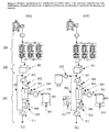
- FIG. 1 shows 2 embodiments of inventive device A.
- the integrated continuous particle removal system (100) is directly connected to the harvest side of the continuous perfusion fermentation system (1).
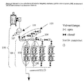
- FIG. 4 shows a more detailed schematic representation of an embodiment of the inventive integrated continuous particle removal system (100), which consists of a pump (101), a pressure gauge or transmitter, respectively (107), a connection manifold (102) and an assembly of several filter trains (103). All components are connected with flexible tubing and/or hard piping.
- the pump (101) is a conventional peristaltic pump, which allows gentle pumping of the cell culture harvest without any rotating parts or seals contacting the sterile product.
- the pump and the pump tubing is sized to deliver the desired harvest flow rate of the cell culture fermentation system, which is up to 15 bioreactor volumes per day, e.g. up to 9.4 liters/hour for a 15 liter fermenter and up to 125 liters/hour for a 200 liter fermenter.
- the pressure gauge or pressure transmitter (107) is designed such that it can be sterilized by autoclaving or irradiation.
- a re-usable piezoresitive transmitter in a stainless steel housing or a re-usable stainless steel pressure gauge are used.
- future improvements can include the use of disposable transmitters which can easily be sterilized by irradiation.
- connection manifold (102) consists of flexible tubing, with tubing clamps (or valves) and appropriate sterile connectors for allowing connection of additional filter train assemblies without compromising system sterility.
- the tubing diameters are sized to yield linear fluid velocities of about 2 m/s or less at the desired flow rates, thereby avoiding high backpressures and shear.
- special flexible tubing pieces are used that can be welded with commercial tubing welders without compromising sterility. Such tubing pieces are made of PVC or other suitable polymers.
- the filter train assembly (103) consist of at least two, preferably multiple identical filter trains (as shown in schematic), with only one of the filter trains open at any given time, as shown as an example in the Figure 4 (105).
- Each filter train consists of at least one filter, preferably one pre-filter and one final filter in series (as shown in Figure 4 ). If required to increase capacity for a specific application, each filter train (105, 106 etc.) itself can also consist of multiple filters or filter trains in parallel (not shown).
- the second filter train of the assembly (106) is closed off by a pressure-sensitive rupture disc, or rupture pin, respectively (104).
- the function of the rupture disc, or rupture pin is to automatically open up the flow-path to the second filter train (107) once the pressure in the first filter train (105) reaches a specified limit, thereby ensuring uninterrupted continuation of the filtration process.
- Commercially available rupture discs or rupture pins are utilized in the inventive system, which are otherwise used to provide safety pressure relief.
- rupture discs or rupture pins with a specified rupture pressure limit of not more than 16 PSI are used, which has proven to be very useful. However, a range of specified pressure limit is possible.
- Each further filter train of the filter train assembly is also separated by a manual or automatic valve and another rupture disc or rupture pin. Once the second filter train (106) is operational, the valve to the next rupture disc or rupture pin, respectively, is opened, so that the next filter train can act as a backup and so forth.
- automatically actuated valves are used exclusively, and in operation, a control system actuates the valves based on the input of a piezoresitive pressure sensor (107) which can also be sterilized by autoclaving.
- a piezoresitive pressure sensor (107) which can also be sterilized by autoclaving.
- the present design comprising the rupture disc or rupture pin, respectively, provides outstanding robustness in long-term operation.
- the final filter rating is at least 3 ⁇ m or smaller, preferably 0.45 ⁇ m and still preferably 0.2 ⁇ m.
- the operating filter train (6) therefore retains all remaining cells, as well as, relevant cell debris and other particles, resulting in a particle-free output stream (9), the clarified tissue culture fluid (cTCF).
- each filter train (105, 106 etc.) of the assembly (103) consists of 3 30" pre-filter capsules (Kleenpak Ultipleat, Pall Corp., 4.5 um rated, 0.75 m 2 each) followed by 3 20" final filter capsules (Sartobran P, Sartorius, 0.45 um/0.2um rated, 1.3 m 2 each).
- This particular embodiment has been found particularly useful for large-scale manufacturing of recombinant blood coagulation Factor VIII, as well as, genetically engineered FVIII variants including B-domain deleted FVIII.
- novel inventive device and process will also be beneficial for use with novel filter types and geometries, e.g. with filter types that increase available filter area per capsule, as well as, with filter types that provide a cross-flow pattern or other means to minimize cake built-up, such as vibration or filter element rotation.
- the filter train assembly (103) comprises only one sterile back up filter train closed by a rupture disc or rupture pin, respectively, but still multiple filter trains for operation.
- the first filter train of the assembly is operated until a specified pre-determined loading volume has been processed, after which operation is switched over (manually or automatic) to the next filter train in the assembly.
- the specific loading volume is specified so that under normal operating conditions the pressure limit of the rupture disc or rupture pin is not exceeded. If however the pressure increases more then usual during filtration, e.g. due to an unusually low filterability of the harvest, the back-up filter train ensures again uninterrupted continuous filtration by opening up once the specified pressure is exceeded. Following an opening of the back-up filter train, filtration is switched to another filter train of the assembly and another back-up filtration train with rupture disk or rupture pin is installed without compromising the sterility of the system.
- batch filter trains need to be sized to have the lowest possible filter area required for providing the desired absolute flow rate (in liters/hour) and maximum pressure.
- the desired absolute flow rate in turn has to be high enough to provide feasible processing times for the desired batch volume. This inherently necessitates a high specific flow rate (in liters/hour/m 2 of filter area).
- the inventive device is designed for several fold lower specific flow rate, which is kept constant (in liters/hour/m 2 of installed filter area) so that the absolute flow rate is equal to the harvest flow rate of the continuous perfusion fermentation.
- the outlet of the integrated continuous particle removal system is directly and constantly connected to a surge vessel (201), as shown in Figure 2 .
- This surge vessel is a sterile vessel, such as, a disposable bag or a stainless steel vessel with at least one inlet port and one outlet port, the later preferably on the bottom of the vessel.
- a broad range of vessel sizes and designs can be utilized.
- the surge vessel is preferably sized to be small compared to the volumetric throughput of the system to keep the residence time of the product in the vessel at a minimum, i.e. below 24 hours, preferably below 8 hours, and still preferably below 4 hours.
- the surge vessel is located on a balance or load cell (202), as shown for device B1 and B2 in Figure 3 .
- This balance or load cell provides a weight signal to a computerized control system (not shown).
- a buffer vessel (204) is connected via a peristaltic pump (203) to the surge vessel.
- this set-up is used to adjust the properties of the particle-free harvest stream, such as conductivity (ionic strength) or pH, by adding suitable buffer or diluent.
- an optional mixing system (205) and sensors to monitor the desired condition (206), such as pH or conductivity are used.
- a magnetically coupled stirrer is used; however, other mixing systems, such as shakers or pulsating devices could be used as well.
- Device A comprises an integrated continuous, sterile ultrafiltration system (300).
- Embodiments of the continuous, sterile ultrafiltration system comprise a recycle pump (301) and recycle loop (306), one or more sterile crossflow ultrafiltration modules (303), a permeate pump (305), a sterile permeate receiving vessel (307) on a balance or load cell (309) and a retentate pump (311).
- it comprises instrumentation in form of an inlet pressure gauge or transmitter (302), permeate pressure gauge or transmitter (304), outlet pressure gauge or transmitter (308), as well as, a recycle flow meter (310).
- the system outlet (312) provides a continuous stream of concentrated and partially purified protein product, which can be continuously collected, frozen or further processed.
- Inventive embodiment A2 comprises in addition a buffer or diluent vessel (314), a peristaltic buffer/diluent addition pump (313), as well as, flow-through sensors to monitor conditioning of the concentrate in the recycle loop, such as sensors for pH and conductivity (315, 316).
- this set-up is used to adjust the properties of the particle-free harvest stream, such as conductivity (ionic strength) or pH, by adding suitable buffer or diluent.
- This set-up can also be used to add protein stabilizers.
- inventive embodiment A2 the recycle loop itself acts as a mixing chamber
- conditioning can alternatively also be performed by using a surge vessel set-up as shown for device B (embodiment B2), comprising components (203, 204, 205, 206) as discussed later in this disclosure (see description of device B).
- Embodiments of the inventive device also comprise a data-logging and programmable control system, which records incoming data signals from the instrumentation (such as, but not limited to, pressures, flow rate, vessel weight, pH, conductivity) and controls the pump speeds according to a pre-defined control algorithm.
- a data-logging and programmable control system which records incoming data signals from the instrumentation (such as, but not limited to, pressures, flow rate, vessel weight, pH, conductivity) and controls the pump speeds according to a pre-defined control algorithm.
- All pumps are peristaltic pumps, which allow pumping of the respective fluid streams without any rotating parts or seals contacting the sterile product stream. Applicants discovered that this is preferable to provide robust sterile long-term operation.
- the recycle pump (301) and its pump tubing is sized to allow robust adjustment of the desired cross-flow rates of between 80 and 800 liters/hour per m 2 of installed membrane area, depending on the mass transfer characteristics of the ultrafiltration module used.
- the permeate pump is sized to allow robust and precise adjustment of a specific permeate flux of between 90% and 99% of the harvest flow rate from the continuous perfusion fermentation.
- the retentate pump is sized to allow a robust and precise adjustment of the retentate flow of between 1% and 10% of the harvest flow rate from the continuous perfusion fermentation.
- Encapsulated ultrafiltration modules (303) are used to allow robust sterile operation, and are sterilized by autoclaving or irradiation.
- the optimal nominal molecular weight cut-off is chosen based on the molecular weight of the protein product of interest and has to be confirmed by standard experiments known to those in the art.
- a variety of membrane materials, such as polyethersulfone, hydrophilized polyethersulfone or regenerated cellulose can be used, as long as the entire membrane module can be sterilized by irradiation and/or autoclaving without damaging the membrane. It is expected that hydrophilic materials can increase efficiency due to their lower fouling tendencies.
- device A is uniquely efficient if the installed total ultrafiltration membrane area in square meters is equal to a range of between 0.1 to 2 times the volumetric flow rate of the harvest from the continuous perfusion fermentation in liters/hour. E.g. for a perfusion harvest flow rate of 1 liter/hour, the installed total membrane area should be between 0.1 and 2 square meters. Applicants discovered that the device A is yet more efficient, if the installed ultrafiltration membrane area in square meters is equal to a range of between 0.3 to 1 times the volumetric flow rate of the harvest from the continuous perfusion fermentation in liters/hour.
- encapsulated membranes and module designs such as spiral wound modules, encapsulated cassettes or capsules with enhanced mass transfer due to secondary flow patterns (e.g. vortex flow), rotating elements (e.g. dynamic disk filters) or vibrating filters.
- secondary flow patterns e.g. vortex flow
- rotating elements e.g. dynamic disk filters
- vibrating filters e.g. vibrating filters.
- especially encapsulated ultrafiltration cassettes can be used beneficially in the inventive devices since they provide high mass transfer coefficients at relatively low required cross-flow rate, thereby reducing pump capacity, while keeping system complexity and investment costs low.
- the inventive device allows not only continuous, but also truly sterile operation, in contrast to just aseptic operation. Applicants achieved this by designing all product-contacting system components to withstand not only cleaning, but also sterilization by autoclaving, steaming in place or gamma-irradiation.
- disposable encapsulated modules are used for continuous particle removal (100), as well as, continuous ultrafiltration (300).
- Peristaltic pumps are used to avoid any product contact with rotating elements and mechanical seals.
- disposable tubing and bag assemblies are used instead of hard piping.
- Disposable product contacting components e.g. tubing, bags, modules
- component groups are pre-assembled and sterilized together, thereby simplifying start-up and operation.
- the systems are designed to keep any potential opening of the sterile system to the environment (e.g. laminar flow hood), as for sampling, bag or instrumentation exchange to a minimum.
- manifolds are designed redundant to allow switching from one sterile component (e.g. product receiving bag) to the next without opening. Additional exchange of tubing, modules or bags is preferably performed by using sterile tubing welders rather then sterile connectors.
- inventive devices could also comprise components such as stainless steel vessels, filter housings or piping that can be sterilized in place, alone or in combination with disposable components, as long as robustness and sterility in long-term operation is assured.
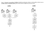
- inventive device A is designed to process material from multiple fermenters in larger manufacturing plants (A3).
- An example is shown schematically in Figure 5 .
- Further embodiments are designed to increase the overall concentration factor and separation performance by combining 2 stages of continuous ultrafiltration systems (300) in series (A4, shown schematically in Figure 5 ).
- the continuous perfusion fermentations are operated over a long period of time (one campaign), typically between 2 weeks and 6 months or more.
- the tissue culture fluid (TCF) containing product, cells and cell-debris is continuously processed using the device A.
- a sterile, particle-free, concentrated and partially purified product stream (the "product isolate") is produced and continuously leaves the device at its outlet (312).
- the pump (101) of the continuous, sterile particle removal system (100) the harvest is pumped continuously through the filtration assembly (103) at the desired perfusion harvest flow rate Qh of the fermentation.
- the output stream of the continuous filtration system i.e. the clarified tissue culture fluid (cTCF) continuously enters the surge vessel (201).
- the cTCF is continuously processed by a continuous, sterile ultrafiltration system (300) at a flow rate equal to the flow rate coming from the continuous perfusion fermentation. Due to the small sizing of the surge vessel relative to the adjusted flow rates, the mean residence time of the product in the vessel is kept at a minimum, i.e. below 12 hours, preferably below 4 hours and still preferably below 2 hours.
- Adequate crossflow and thus mass transfer is adjusted in the ultrafiltration module via the recycle pump (301).
- the retentate flow rate is adjusted and controlled by using the retentate pump (311), thus yielding a constant and continuous flow rate Qi of the concentrated product isolate leaving device A at it's outlet (312).
- the permeate pump (305) is used to adjust and control the flow rate Qp of the permeate, which is drawn continuously from the permeate side of the ultrafiltration module(s), and which consists of water and solutions components small enough to pass through the ultrafiltration membrane (e.g. salts, small proteins).
- the ultrafiltration system automatically draws a flow of Qp + Qi from the small surge vessel (201).
- the novel method of using device A also contrasts with the UF batch processes (prior art) in terms of the operational set-point of the ultrafiltration itself.
- Conventional Batch UF processes are designed for a certain throughput through a low membrane area in a short period of time. Batch UF is thus generally operated at the transition point of pressure dependent to mass transfer controlled region (see Figure 9 ). This leads to a desirably high initial specific flux, which however drops significantly and rapidly over the course of seconds to minutes, as concentration polarization leads quickly to osmotic back-pressure and the formation of a limiting gel layer (secondary membrane).
- Such a high wall concentration of macromolecules also leads to an increased adsorption of compounds to the inner and outer membrane surface, i.e. to membrane fouling. This fouling would further reduce the permeate flux over time.
- the continuous UF is operated at optimized mass transfer coefficient to minimize concentration polarization.
- applicants adjust the permeate flux J to be at the low end of the pressure-flux curve (see Figure 9 ).
- the wall concentration cwall at the surface of the membrane is therefore significantly lower than it would be in batch ultrafiltration.
- the present embodiment of the inventive method adjusts a target specific permeate flux of approximately 1/10 of the achievable mass transfer coefficient, thereby adjusting a wall concentration of only 10% above the adjusted bulk (or retentate) concentration.
- Table 1 shows an example of a method for using device A (embodiment Al) for continuous isolation of a protein product from a development scale fermenter: Table 1 Example of method for using a present embodiment of device A for continuous isolation of a protein product from continuous perfusion fermentation Operational Parameter Target Harvest flow rate Qh from continuous perfusion (controlled with pump 101) 5 liters/hour (120 liters/day) Permeate flow rate QP (controlled with pump 305) 4.75 liters/hour Retentate (product isolate) flow rate Qi (controlled with pump 311) 0.25 liters/hour Specific permeate flux J 2 liters/hour/m2 Concentration factor cf 20 fold
- a lifetime criteria can be defined for the sterile continuous ultrafiltration set-up, e.g. based on trans-membrane pressure. Once the trans-membrane pressure limit is exceeded, the continuous sterile ultrafiltration set-up is exchanged against another identical set-up without compromising integrity and sterility of the system. This can be done in analogy to the continuous, sterile filtration set-up by using either manifolds and sterile connectors, or by using disposable flexible tubing and sterile tubing welders.
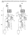
- FIG 3 shows 2 embodiments of inventive device B.
- the integrated continuous particle removal system (100) is directly connected to the harvest side of the continuous perfusion fermentation system (1).
- This part of device B is identical to device A (see detailed description of device A and Figure 4 , above).
- the outlet of the integrated continuous particle removal system is directly and constantly connected to a surge vessel (201), as shown in Figure 3 .
- This surge vessel is a sterile vessel, such as, a disposable bag or a stainless steel vessel with at least one inlet port and one outlet port, the later preferably on the bottom of the vessel.
- a broad range of vessel sizes and designs can be utilized.
- the surge vessel is preferably sized to be small compared to the volumetric throughput of the system to keep the residence time of the product in the vessel low, i.e. below 26 hours, preferably below 12 hours and still preferably below 4 hours.
- the surge vessel is located on a balance or load cell (202), as shown for embodiments B1 and B2 in Figure 3 .
- This balance or load cell provides a weight signal to a computerized control system (not shown).
- a buffer vessel (204) is connected via a peristaltic pump (203) to the surge vessel.
- this set-up is used to adjust the properties of the particle-free harvest stream, such as conductivity (ionic strength) or pH, by adding components for modifying the properties of the clarified tissue cultured received from the particle removal system, such as a suitable buffer or diluent, or a suitable protein stabilizer.
- a present embodiment also comprises a mixing system (205) and sensors to monitor the desired condition (206), such as pH or conductivity, are used.
- a magnetically coupled stirrer is used; however, other mixing systems, such as shakers or pulsating devices could be used as well.
- 2 surge vessels are used. At any given time, one surge vessel is directly connected to the continuous particle removal system (100), thereby receiving clarified fluid, while the other one is connected to the semi-continuous concentration/purification system (400), thereby feeding a convective adsorption/desorption cycle. Switching between both is realized through a control system, using the weight of the receiving vessel to trigger a switch once its maximum filling volume is reached.
- Device B 2 embodiments of which are shown in Figure 3 , comprises an integrated semi-continuous, convective adsorption/desorption system (400).
- the integrated semi-continuous convective adsorption/desorption system is designed and sized so that its loading flow rate (Qload) is significantly higher than the flow rate of the continuous perfusion harvesting and continuous filtration process (Qh), i.e. Qload >> Qh.
- Embodiments of the integrated semi-continuous concentration/purification system (400) comprise a load pump (401), a multi-port valve assembly (402) and several buffer vessels (404), a 3-way-valve (403) connected to a sterile waste receiving vessel (413) and one or more convective adsorber module(s) (406), inlet- and outlet-pressure gauges or transmitters (405, 408), further instrumentation such as UV sensor (409), pH and conductivity sensors (409, 410), flow meter (412), as well as, another 3-way valve (407) connected also to the waste vessel (413) and the product eluate outlet (414).
- a load pump 401
- a multi-port valve assembly 402
- buffer vessels 404
- a 3-way-valve 403 connected to a sterile waste receiving vessel (413) and one or more convective adsorber module(s) (406), inlet- and outlet-pressure gauges or transmitters (405, 408), further instrumentation such as UV sensor (409
- Embodiments of the inventive device also comprise a data-logging and programmable control system (not shown), which records incoming data signals from the instrumentation (such as, but not limited to, pressures, UV, pH, conductivity, flow rate, surge vessel weight) and controls the automated valves and pump according to programmed protocols.
- a data-logging and programmable control system (not shown), which records incoming data signals from the instrumentation (such as, but not limited to, pressures, UV, pH, conductivity, flow rate, surge vessel weight) and controls the automated valves and pump according to programmed protocols.
- the load pump (401) is preferably a peristaltic pump to avoid direct contact of product or sterile buffers with any seals or mechanical parts. Applicants discovered that this is preferable to provide robust sterile long-term operation. However, other sterile pump designs can in principal be used.
- the load pump is sized depending on the installed matrix volume of the convective adsorber (406) to allow robust adjustment of at least 12 matrix volumes/minute. E.g., in one present embodiment, Mustang membrane adsorber capsules (Pall Corp.) are used that have a matrix volume of approx. 0.3 liters. Therefore, the load pump is sized to allow loading flow rates of up to 3.6 liters/minute.
- the function of the multi-port valve assembly (402) is to allow switching between the product containing load drawn from the surge vessel (201) and each of the sterile buffers and cleaning solutions from the sterile buffer vessels (404).
- Present embodiments of device B utilize a series of automatically actuated pinch valves, which pinch the flexible tubing connected to each buffer vessel from the outside to close of and open each line. Applicants discovered that these pinch valves provide a particularly beneficial solution for device B since they avoid any product contact and thus do not need to be cleaned or sterilized.
- actuated membrane valves such as actuated membrane valves.
- the 3-way valves (403, 407) are autoclavable actuated membrane valves.
- a variety of commercial valves suitable for sterile processing can in principal be used, including e.g. pinch valves.
- the convective adsorber module (406) contains a chromatographic matrix with pre-dominantly convective mass transfer of the product to the adsorptive surface and, in contrast to conventional chromatography, is sterilized prior to operation by autoclaving, steaming or irradiation.
- the predominantly convective mass transfer allows, in contrast to conventional packed bed chromatography, very low adsorption/elution/regeneration cycle times, which applicants utilize in inventive device to realize semi-continuous operation.
- the convective adsorber (406) consists of one or more commercially available membrane adsorber capsule(s) with ion exchange chemistry (Mustang, Pall corporation or Sartobind, Sartorius).
- the device can utilize other membrane adsorber materials and geometries and novel convective matrices such as monolithic matrices as well, since in contrast to conventional chromatography resin packing is eliminated and matrices can generally be encapsulated in ready-to-use modules.
- multiple convective adsorber modules are used in the device in form of an assembly of convective adsorber-trains in parallel, similar to the continuous particle removal system (100).
- the entire assembly with all adsorber-trains is sterilized together, allowing in operation switching from one adsorber-train to a fresh one should the first one reach the end of its useful life, as determined e.g. by a pre-defined criteria such as back-pressure during loading or maximum number of performed operating cycles.
- Each adsorber-train consists of either one individual module or multiple convective adsorber modules in parallel and/or in series to increase binding capacity and/or improve capacity utilization.
- inventive device allows not only continuous, but also truly sterile operation in contrast to just aseptic operation.
- disposable encapsulated modules are used for continuous particle removal (100), as well as, semi-continuous sterile convective adsorption/desorption (400).
- Peristaltic pumps are used to avoid any product contact with rotating elements and mechanical seals.
- disposable tubing and bag assemblies are used instead of hard piping.
- Disposable product contacting components e.g. tubing, bags, modules
- component groups are pre-assembled and sterilized together, thereby simplifying start-up and operation.
- the systems are designed to keep any potential opening of the sterile system to the environment (e.g. laminar flow hood), as for sampling, bag or instrumentation exchange to a minimum.
- manifolds are designed redundant to allow switching from one sterile component (e.g. product receiving bag) to the next without opening. Additional exchange of tubing, modules or bags is preferably performed by using sterile tubing welders rather then sterile connectors.
- inventive devices could also comprise components such as stainless steel vessels, filter housings or piping that can be sterilized in place, alone or in combination with disposable components, as long as robustness and sterility in long-term operation is assured.
- inventive device B are designed to process material from multiple fermenters in larger manufacturing plants (B3).
- An example is shown schematically in Figure 6 .
- Further embodiments of inventive device B are designed to increase the overall concentration factor and separation performance by combining multiple convective adsorption/desorption systems (400) in series, with respective sterile surge vessels in between (200) (see Figure 6 , B4).
- inventive devices are designed to increase the overall concentration factor and separation performance by combining a continuous ultrafiltration system (300) in series with a semi-continuous convective adsorption/desorption system (400) via an additional surge vessel.
- a continuous ultrafiltration system 300
- a semi-continuous convective adsorption/desorption system 400
- An example of an embodiment is shown schematically in Figure 7 .
- the continuous perfusion fermentations are operated over a long period of time (one campaign), typically between 2 weeks and 6 months or more.
- the tissue culture fluid (TCF) containing product, cells and cell-debris is continuously processed using the device B.
- a sterile, particle-free, concentrated and partially purified product stream (the "product isolate") is produced and continuously leaves the device at its outlet (414).
- the pump (101) of the continuous, sterile particle removal system (100) the harvest is pumped continuously through the filtration assembly (103) at the desired perfusion harvest flow rate Qh of the fermentation.
- the output stream of the continuous filtration system i.e. the clarified tissue culture fluid (cTCF) continuously enters the surge vessel (201).
- cTCF clarified tissue culture fluid
- a weight or level signal triggers automatically an adsorption/desorption cycle of the integrated, sterile semi-continuous concentration/purification system.
- the material collected in the surge vessel is loaded rapidly onto the adsorber set-up, i.e. within 4 hours, preferably within 2 hours, and still preferably within 1 hour or less, thus emptying the surge vessel.
- the loaded adsorber undergoes more steps of a pre-defined chromatographic protocol, designed to desorb the target product in concentrated, purified form and to ready the adsorber for the next loading cycle.
- the overall cycle comprises loading, wash, elution, regeneration and reequilibration, each with one or more suitable buffers.
- total cycle time is kept low, i.e. below 6 hours, preferably below 3 hours and still preferably below 1.5 hours. Therefore, the integrated system is designed so that the adsorber set-up is ready for the next loading cycle before the surge vessel is filled again, thus allowing semi-continuous operation.
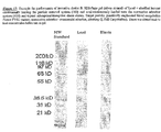
- Table 2 shows an example of a method of using a present embodiment of the inventive device B for isolation of recombinant human blood-coagulation Factor VIII (large scale data shown).
- the method proved uniquely beneficial. Yields and performance of each adsorption/desorption cycle was similar to batch, with the overall product yield increased by more than 10% due to the lower residence time of the product and thus minimized product degradation.
- the same method has also proven to be very beneficial for the isolation of genetically engineered FVIII variants, including B-domain deleted FVIII, which is significantly different from full-length FVIII in size and other characteristics. It is expected to be useful for production of other proteins and biomolecules as well.
- a lifetime criteria is defined for the convective adsorber set-up, e.g. based on pressure during loading, or recovery.
- a maximum number of cycles nmax is specified and validated.
- a sterile stream of buffer, pH adjustment solution, stabilizer solution or water for injection is added either continuously or intermittently from a sterile vessel (204) using a buffer addition pump (203). Therefore, the conditions of the cTCF can be freely adjusted, e.g. in terms of ionic strength, pH, addition of stabilizers etc.
- inventive devices and respective methods of using the devices solve the problems of conventional isolation processes outlined before (see general background of the invention).
- the devices and respective methods eliminate the need for large cold room facilities or cooled vessels for intermediate storage of large harvest volumes, thereby reducing plant investment costs and fully realizing the compactness and mobility advantage of perfusion fermentation.
- Embodiments of both inventive devices and respective methods reduce labor costs compared to conventional, labor-intensive batch processing due to the inherently high degree of automation.
- the novel devices allow continuous operation, 24 hours a day, over long periods of time, maximizing volumetric throughput and equipment utilization.
- inventive devices eliminate logistical difficulties in plants of one or multiple fermenters.
- Embodiments can process material from either one or multiple continuous perfusion fermentations.
- inventive devices enable avoiding or minimizing the need for cleaning validation due to the utilization of disposables.
- disposable modules, as well as, tubing, bags and assemblies can be used each for a long period of time (up to the entire length of the campaign), thereby dramatically lowering costs and making the utilization of disposables highly attractive from an economic standpoint.
- inventive devices A and B and respective methods have proven to be especially useful for manufacturing of recombinant blood coagulation Factor VIII, as well as, genetically engineered versions of FVIII including, but not limited to, B-domain deleted FVIII.
- the inventions can clearly be expected to be similarly useful for the production of other proteins and biological molecules, in particular complex inherently unstable proteins such as Factor VII, Factor IX, Factor X, and others.
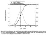
- Figure 8 shows an example of the surprising filter capacity increase applicants discovered for the integrated continuous particle removal element (100).
- Figure 10 shows a typical residence time distribution and mean residence time of the product in the continuous UF system (300) of an embodiment of inventive device A, as determined by UV adsorption of the retentate at 280nm, with a model protein under typical conditions.
- the mean residence time of the product in the system is only approximately 40 minutes. Therefore, the total residence time of the product in this present embodiment of device A, from fermenter harvest line to the final, concentrated retentate (isolate) is kept within 1-2 hours or less. This is less then 1/10 of the residence time of 28 hours or more in a conventional batch isolation process, in which the product (harvest) is collected for at least 24 hours (to several days), after which the product is processed for typically at least 4-10 hours.
- Figure 11 shows a comparison of the resulting total isolation yields of recombinant blood coagulation factor (rFVIII) from plasma-protein free continuous perfusion fermentation for both a conventional batch isolation process (batch filtration plus batch UF) and using the inventive device A and respective method.
- rFVIII recombinant blood coagulation factor
- the transmembrane pressure of the integrated continuous ultrafiltration is going to increase with time, while the specific membrane flux (in liters/hour/m 2 /bar) is decreasing at constant volumetric throughput.
- This is common to all ultrafiltration processes and is due to effects like concentration polarization, gel-layer formation and fouling.
- the changes of pressure and specific flux are extremely slow with device A, allowing continuous operation for weeks at a time, before the membranes need to be cleaned or replaced.
- the rate of change and overall performance of the system is quite insensitive to the product produced or the cell-line used in the continuous perfusion fermentation ( Figure 12 ). Therefore, the inventive device A and respective method is also ideally suited as a generic platform for rapid production of various proteins since it performs robustly and predictably with various target proteins from different cell-lines.
- FIG. 13 shows the robust performance of the inventive device A in a long-term run. After approximately 25 days, the transmembrane pressure surprisingly appeared to stabilize in a quasi-steady-state, suggesting even higher long-term performance. On day 27, the retentate flow rate was purposefully doubled to test the effect of higher throughput. After 34 days, a short flush was performed with sterile 0.5 M NaOH, without opening the system, and thus while maintaining full system integrity and sterility. After this, the TMP again stabilized, or at least increased only at an extremely low rate.
- the recycle flow rate was purposefully reduced in half to test the effect on system performance.
- the TMP started to increase with a somewhat higher rate due to the reduced mass transfer and thus increased wall concentration at the membrane surface.
- 95 days of operation were successfully and robustly completed before the system was turned off.
- a total of close to 4500 liters have been processed per m 2 of membrane area, with minimal manual labor (daily sampling only).
- the optimized conventional batch ultrafiltration process for the same application has 45-fold less loading capacity, at approx. 100 l/m 2 , and requires at least 1-2 operators full time.
- the selectivity of the inventive device A in particular its integrated continuous ultrafiltration system (300), proved to be significantly higher then the selectivity of a conventional batch process. It is well known to those familiar with the field that in conventional batch ultrafiltration, a secondary membrane is formed from retained macromolecules during the initial stage of the process (gel layer), which reduces the apparent molecular weight cut-off. The result is that both the target molecule and contaminating smaller proteins are retained, which makes significant simultaneous purification practically impossible. Therefore, with conventional batch ultrafiltration it is seldom possible to separate proteins that are less then a factor of 10 apart in terms of their molecular weight. However, as can be seen from Figure 14 , with the inventive integrated continuous ultrafiltration process it is possible to adjust conditions to efficiently separate IL-2SA (approx. 16 kD) and green fluorescent protein GFP (27-30 kD). This higher then expected separation performance does allow for simultaneous concentration and purification.
- IL-2SA approximately 16 kD
- GFP green fluorescent protein
- Figure 15 illustrates the performance of the inventive device B.
- a commercial convective adsorber Mov Q, Pall Corporation, 15 layer module
- close to 100 consecutive adsorption/desorption cycles have been performed, thereby concentrating and purifying a recombinant FVIII variant from continuous perfusion culture.
- the average yield achieved was approximately 95% (spread results from assay variation), while the pressure remained relatively constant over the entire number of cycles performed. Therefore, it can be specified that at least 100 consecutive cycles can be performed before exchanging the adsorber set-up.
- the total mean residence time of the product in a present embodiment is less than 3 hours, before it is eluted in concentrated, purified and stabilized form in an appropriate buffer. This is significantly less then the more than 24 hours residence time in a conventional batch isolation process performed once daily and therefore results in significantly higher yields of the inherently labile protein products.
- approximately 13 cycles are performed per day, which means in context of Figure 15 that the semi-continuous adsorber assembly would need to be exchanged only every 7-8 days, which is done without compromising sterility and continuity of operation.
- Figure 16 shows an example of the UV and conductivity profile over a single typical adsorption/desorption and regeneration cycle with device B. It can be seen that more then 450 adsorber volumes (CVs) can be loaded, while the product elutes in a very sharp peak. Contaminants are removed significantly in the flow through during the loading phase, as well as, during the wash and the strip (regeneration phase).
- CVs adsorber volumes
- Figure 17 illustrates the purification performance of the inventive process comprising semi-continuous convective adsorption/desorption.
- An example SDS page gel of a FVIII variant isolate is shown.
- the eluate fractions which include 95% of the loaded FVIII variant (as determined by separate activity assay), contain significantly less protein than the load and are thus purified. No additional degradation bands are visible in the eluate (isolate), indicating excellent product quality.
- the inventive device B is able to achieve similar purification performance as comparable batch processes, while at the same time minimizing yield losses for inherently unstable protein products, as well as, product quality issues, due to the minimization of product residence time.
- labor costs are dramatically reduced due to the inherently high degree of automation of the inventive process, requiring minimal operator intervention.
Priority Applications (2)
| Application Number | Priority Date | Filing Date | Title |
|---|---|---|---|
| EP12179336.8A EP2550971B1 (en) | 2004-09-30 | 2005-09-30 | Devices and Methods for Integrated Continuous Manufacturing of Biological Molecules |
| DK12179336.8T DK2550971T3 (en) | 2004-09-30 | 2005-09-30 | Devices and methods for integrated continuous production of biological molecules |
Applications Claiming Priority (2)
| Application Number | Priority Date | Filing Date | Title |
|---|---|---|---|
| US61499504P | 2004-09-30 | 2004-09-30 | |
| PCT/US2005/035364 WO2006039588A2 (en) | 2004-09-30 | 2005-09-30 | Devices and methods for integrated continuous manufacturing of biological molecules |
Related Child Applications (2)
| Application Number | Title | Priority Date | Filing Date |
|---|---|---|---|
| EP12179336.8A Division EP2550971B1 (en) | 2004-09-30 | 2005-09-30 | Devices and Methods for Integrated Continuous Manufacturing of Biological Molecules |
| EP12179336.8A Division-Into EP2550971B1 (en) | 2004-09-30 | 2005-09-30 | Devices and Methods for Integrated Continuous Manufacturing of Biological Molecules |
Publications (3)
| Publication Number | Publication Date |
|---|---|
| EP1807101A2 EP1807101A2 (en) | 2007-07-18 |
| EP1807101A4 EP1807101A4 (en) | 2010-03-24 |
| EP1807101B1 true EP1807101B1 (en) | 2016-04-13 |
Family
ID=36143124
Family Applications (2)
| Application Number | Title | Priority Date | Filing Date |
|---|---|---|---|
| EP05800224.7A Active EP1807101B1 (en) | 2004-09-30 | 2005-09-30 | Devices and methods for integrated continuous manufacturing of biological molecules |
| EP12179336.8A Active EP2550971B1 (en) | 2004-09-30 | 2005-09-30 | Devices and Methods for Integrated Continuous Manufacturing of Biological Molecules |
Family Applications After (1)
| Application Number | Title | Priority Date | Filing Date |
|---|---|---|---|
| EP12179336.8A Active EP2550971B1 (en) | 2004-09-30 | 2005-09-30 | Devices and Methods for Integrated Continuous Manufacturing of Biological Molecules |
Country Status (25)
| Country | Link |
|---|---|
| US (3) | US9045725B2 (es) |
| EP (2) | EP1807101B1 (es) |
| JP (2) | JP5579966B2 (es) |
| KR (2) | KR101335936B1 (es) |
| CN (2) | CN102794109B (es) |
| AU (1) | AU2005292358B2 (es) |
| BR (1) | BRPI0515849B1 (es) |
| CA (1) | CA2579845C (es) |
| CY (1) | CY1117699T1 (es) |
| DK (2) | DK2550971T3 (es) |
| ES (2) | ES2570006T3 (es) |
| HK (1) | HK1110519A1 (es) |
| HR (1) | HRP20070097B1 (es) |
| HU (2) | HUE027136T2 (es) |
| IL (5) | IL181775A (es) |
| LT (1) | LT2550971T (es) |
| NO (2) | NO341439B1 (es) |
| NZ (2) | NZ554307A (es) |
| PL (1) | PL1807101T3 (es) |
| PT (1) | PT2550971T (es) |
| RU (1) | RU2390526C2 (es) |
| SI (1) | SI2550971T1 (es) |
| UA (3) | UA107937C2 (es) |
| WO (1) | WO2006039588A2 (es) |
| ZA (1) | ZA200702578B (es) |
Families Citing this family (71)
| Publication number | Priority date | Publication date | Assignee | Title |
|---|---|---|---|---|
| HUE027136T2 (en) | 2004-09-30 | 2016-08-29 | Bayer Healthcare Llc | Tools and procedures for the integrated, continuous production of biological molecules |
| US8911964B2 (en) | 2006-09-13 | 2014-12-16 | Abbvie Inc. | Fed-batch method of making human anti-TNF-alpha antibody |
| EP2064314A4 (en) | 2006-09-13 | 2009-12-30 | Abbott Lab | IMPROVEMENTS TO CELL CULTURE |
| FR2920429B1 (fr) * | 2007-08-30 | 2012-10-05 | Lfb Biotechnologies | Procede de purification du facteur viii et du facteur von willebrand |
| BRPI0920572A8 (pt) | 2008-10-20 | 2015-10-27 | Abbott Lab | Inativação viral durante a purificação dos anticorpos |
| EP2350127B1 (en) | 2008-10-20 | 2015-01-28 | AbbVie Inc. | Isolation and purification of antibodies using protein a affinity chromatography |
| US9527010B2 (en) | 2009-09-25 | 2016-12-27 | Ge Healthcare Bio-Sciences Corp. | Separation system and method |
| JP5860887B2 (ja) * | 2010-10-15 | 2016-02-16 | ジーイー・ヘルスケア・バイオサイエンス・コーポレイション | 大容量使い捨て限外濾過システム及び方法 |
| CN102154408B (zh) * | 2011-01-13 | 2013-06-05 | 天津市工业微生物研究所 | 小核菌硬葡聚糖在线发酵提取方法及系统 |
| WO2012122413A1 (en) * | 2011-03-08 | 2012-09-13 | University Of Maryland Baltimore County | Microscale bioprocessing system and method for protein manufacturing |
| US10774304B2 (en) * | 2011-03-08 | 2020-09-15 | University Of Maryland, Baltimore County | System and method for production of on-demand proteins in a portable unit for point of care delivery |
| US9982227B2 (en) | 2011-03-08 | 2018-05-29 | University Of Maryland, Baltimore County | System and method for production of on-demand proteins in a portable unit for point of care delivery |
| WO2012149197A2 (en) | 2011-04-27 | 2012-11-01 | Abbott Laboratories | Methods for controlling the galactosylation profile of recombinantly-expressed proteins |
| EP2766970A4 (en) * | 2011-10-11 | 2016-01-27 | Guardian F D S Llc | PRESSURE RELIEF SYSTEM FOR AN ELECTRIC TRANSFORMER |
| JP6227562B2 (ja) | 2012-01-18 | 2017-11-08 | バイエル・ヘルスケア・エルエルシーBayer HealthCare LLC | 灌流バイオリアクターシステムおよびその操作方法 |
| US9997264B2 (en) * | 2012-02-14 | 2018-06-12 | Control Components, Inc. | Enhanced nuclear sump strainer system |
| US9067990B2 (en) | 2013-03-14 | 2015-06-30 | Abbvie, Inc. | Protein purification using displacement chromatography |
| WO2013158273A1 (en) | 2012-04-20 | 2013-10-24 | Abbvie Inc. | Methods to modulate c-terminal lysine variant distribution |
| WO2013158279A1 (en) | 2012-04-20 | 2013-10-24 | Abbvie Inc. | Protein purification methods to reduce acidic species |
| US9249182B2 (en) | 2012-05-24 | 2016-02-02 | Abbvie, Inc. | Purification of antibodies using hydrophobic interaction chromatography |
| EP2682168A1 (en) | 2012-07-02 | 2014-01-08 | Millipore Corporation | Purification of biological molecules |
| US9206390B2 (en) | 2012-09-02 | 2015-12-08 | Abbvie, Inc. | Methods to control protein heterogeneity |
| US9512214B2 (en) | 2012-09-02 | 2016-12-06 | Abbvie, Inc. | Methods to control protein heterogeneity |
| DK2958989T3 (en) | 2013-02-22 | 2019-03-25 | Genzyme Corp | MICRO-CARRIER PERFUSION CULTURE PROCEDURES AND APPLICATIONS THEREOF |
| SG11201506343QA (en) | 2013-02-22 | 2015-09-29 | Genzyme Corp | Microcarrier perfusion culturing methods and uses thereof |
| SG11201506775VA (en) | 2013-03-08 | 2015-09-29 | Genzyme Corp | Continuous purification of therapeutic proteins |
| EP2830651A4 (en) | 2013-03-12 | 2015-09-02 | Abbvie Inc | HUMAN ANTIBODIES THAT BIND TNF-ALPHA AND PREPARATION METHODS |
| US9017687B1 (en) | 2013-10-18 | 2015-04-28 | Abbvie, Inc. | Low acidic species compositions and methods for producing and using the same using displacement chromatography |
| US8921526B2 (en) | 2013-03-14 | 2014-12-30 | Abbvie, Inc. | Mutated anti-TNFα antibodies and methods of their use |
| US9499614B2 (en) | 2013-03-14 | 2016-11-22 | Abbvie Inc. | Methods for modulating protein glycosylation profiles of recombinant protein therapeutics using monosaccharides and oligosaccharides |
| EP3052640A2 (en) | 2013-10-04 | 2016-08-10 | AbbVie Inc. | Use of metal ions for modulation of protein glycosylation profiles of recombinant proteins |
| US8946395B1 (en) | 2013-10-18 | 2015-02-03 | Abbvie Inc. | Purification of proteins using hydrophobic interaction chromatography |
| US9085618B2 (en) | 2013-10-18 | 2015-07-21 | Abbvie, Inc. | Low acidic species compositions and methods for producing and using the same |
| US9181337B2 (en) | 2013-10-18 | 2015-11-10 | Abbvie, Inc. | Modulated lysine variant species compositions and methods for producing and using the same |
| US20150139988A1 (en) | 2013-11-15 | 2015-05-21 | Abbvie, Inc. | Glycoengineered binding protein compositions |
| TWI709570B (zh) * | 2014-01-17 | 2020-11-11 | 美商健臻公司 | 無菌層析法及製法 |
| TWI709569B (zh) | 2014-01-17 | 2020-11-11 | 美商健臻公司 | 無菌層析樹脂及其用於製造方法的用途 |
| WO2015166083A1 (en) * | 2014-05-02 | 2015-11-05 | Novo Nordisk A/S | Integrated continuous biomanufacturing process |
| US10583397B2 (en) * | 2014-05-13 | 2020-03-10 | Amgen Inc. | Process control systems and methods for use with filters and filtration processes |
| US9975066B2 (en) * | 2014-05-27 | 2018-05-22 | Artificial Cell Technologies, Inc. | Automated layer by layer construction of multilayer coated cores by TFF |
| TW202204596A (zh) | 2014-06-06 | 2022-02-01 | 美商健臻公司 | 灌注培養方法及其用途 |
| TW202246486A (zh) | 2014-06-09 | 2022-12-01 | 美商健臻公司 | 種子罐培養法(seed train processes)及其用途 |
| WO2015195453A2 (en) | 2014-06-16 | 2015-12-23 | Emd Millipore Corporation | Methods for increasing the capacity of flow-through processes |
| WO2015195452A2 (en) | 2014-06-16 | 2015-12-23 | Emd Millipore Corporation | Single-pass filtration systems and processes |
| SG11201508171RA (en) | 2014-06-25 | 2016-01-28 | Emd Millipore Corp | Compact spiral-wound filter elements, modules and systems |
| EP4147769A1 (en) | 2014-08-29 | 2023-03-15 | EMD Millipore Corporation | Processes for filtering liquids using single pass tangential flow filtration systems and tangential flow filtration systems with recirculation of retentate |
| EP3185996B1 (en) | 2014-08-29 | 2022-06-15 | EMD Millipore Corporation | Single pass tangential flow filtration systems and tangential flow filtration systems with recirculation of retentate |
| USD762811S1 (en) | 2014-12-18 | 2016-08-02 | Emd Millipore Corporation | Diverter plate |
| USD761381S1 (en) | 2014-12-18 | 2016-07-12 | Emd Millipore Corporation | Retentate plate |
| EP3093335A1 (de) | 2015-05-13 | 2016-11-16 | Bayer Technology Services GmbH | Prozessleitsystem zur regelung und steuerung einer modular aufgebauten anlage zur produktion von biopharmazeutischen und biologischen makromolekularen produkten |
| ITUA20161506A1 (it) * | 2016-03-09 | 2017-09-09 | Della Toffola Spa | Metodo ed impianto perfezionato di filtrazione tangenziale |
| JP7082453B2 (ja) * | 2016-07-21 | 2022-06-08 | エージェンシー フォー サイエンス,テクノロジー アンド リサーチ | 高体積分率粒子精密濾過のための外壁集束のための装置及びその製造方法 |
| EP3141594A3 (en) * | 2016-11-11 | 2017-06-14 | Bayer Pharma Aktiengesellschaft | Method for sampling fluid streams for monitoring contaminants in a continuous flow |
| AU2017358509A1 (en) * | 2016-11-11 | 2019-05-09 | Bayer Aktiengesellschaft | Method for sampling fluid streams for monitoring contaminants in a continuous flow |
| EP3535047A1 (en) * | 2016-12-09 | 2019-09-11 | Lonza Ltd | Method for the reduction of viral titer in pharmaceuticals |
| EP3354330A1 (en) * | 2017-01-25 | 2018-08-01 | Sartorius Stedim Biotech GmbH | Automated modular filtration system |
| CA2994643A1 (en) * | 2017-02-14 | 2018-08-14 | Bart Lipkens | Bioreactor using acoustic standing waves |
| EP3591030A4 (en) * | 2017-03-03 | 2020-03-25 | FUJIFILM Corporation | CELL CULTURE DEVICE AND CELL CULTURE METHOD |
| JP2018153168A (ja) * | 2017-03-21 | 2018-10-04 | 国立大学法人九州大学 | 微生物収集装置 |
| DE102017110482A1 (de) * | 2017-05-15 | 2018-11-15 | Sartorius Stedim Biotech Gmbh | Filtrationsmodul bzw. Reinigungsmodul für modulares Filtrationssystem |
| DE102017111133A1 (de) | 2017-05-22 | 2018-11-22 | Sartorius Stedim Biotech Gmbh | Vorkonfigurierte Einweg-Filtrationsvorrichtung |
| TWI675696B (zh) * | 2017-06-01 | 2019-11-01 | 美商Emd密理博公司 | 用於灌注應用之切向流過濾裝置 |
| WO2018235871A1 (ja) * | 2017-06-20 | 2018-12-27 | 旭化成株式会社 | 中空糸膜モジュールおよびろ過方法 |
| TW202003832A (zh) * | 2018-05-04 | 2020-01-16 | 美商健臻公司 | 具有過濾系統的灌注式生物反應器 |
| GB201810772D0 (en) * | 2018-06-29 | 2018-08-15 | Ge Healthcare Bio Sciences Ab | Method in bioprocess purification system |
| WO2020046602A1 (en) | 2018-08-31 | 2020-03-05 | Genzyme Corporation | Sterile chromatography resin and use thereof in manufacturing processes |
| US20220119757A1 (en) * | 2019-02-15 | 2022-04-21 | Just-Evotec Biologics, Inc. | Automated biomanufacturing systems, facilities, and processes |
| CN111018968B (zh) * | 2019-12-16 | 2021-07-27 | 兴盟生物医药(苏州)有限公司 | 一种通过超滤浓缩制备高浓度抗体制剂的方法 |
| GB202109015D0 (en) * | 2021-06-23 | 2021-08-04 | Puridify Ltd | A method for purifying a feed in a chromatography system |
| WO2023191008A1 (ja) * | 2022-03-30 | 2023-10-05 | 富士フイルム株式会社 | バイオ医薬品の原薬の製造方法、バイオ医薬品の原薬の製造システム、およびバイオ医薬品の原薬 |
| WO2024072963A1 (en) * | 2022-09-28 | 2024-04-04 | Genzyme Corporation | Systems and devices for producing biological products and methods of using the same |
Family Cites Families (21)
| Publication number | Priority date | Publication date | Assignee | Title |
|---|---|---|---|---|
| US5157113A (en) * | 1987-08-10 | 1992-10-20 | Miles Inc. | Removal of nucleic acids from monoclonal antibody preparations |
| US5256294A (en) * | 1990-09-17 | 1993-10-26 | Genentech, Inc. | Tangential flow filtration process and apparatus |
| US5463029A (en) | 1992-11-23 | 1995-10-31 | Immunex Corporation | Purification of fusion proteins comprising GM-CSF and IL-3 |
| PL183781B1 (pl) * | 1994-05-16 | 2002-07-31 | Merck & Co Inc | Sposób wytwarzania szczepionki przeciwko ludzkiemu wirusowi brodawczaków |
| US5616595A (en) * | 1995-06-07 | 1997-04-01 | Abbott Laboratories | Process for recovering water insoluble compounds from a fermentation broth |
| JP3566461B2 (ja) | 1996-06-28 | 2004-09-15 | ユニ・チャーム株式会社 | 使い捨ての体液吸収性物品 |
| US7122344B2 (en) | 1997-05-28 | 2006-10-17 | Claragen, Inc. | Methods for the production of purified recombinant human uteroglobin for the treatment of inflammatory and fibrotic conditions |
| IT1302026B1 (it) * | 1997-08-22 | 2000-07-20 | Hoffmann La Roche | Materiali immunologici e metodi per la rivelazione di diidropirimidinadeidrogenasi. |
| US6022477A (en) * | 1997-11-14 | 2000-02-08 | New Jersey Institute Of Technology | Method and apparatus for isolation purification of biomolecules |
| US7820796B2 (en) | 1998-03-12 | 2010-10-26 | Genetics Institute, Llc. | Methods for producing Factor VIII proteins |
| US6444223B1 (en) * | 1999-05-28 | 2002-09-03 | Alkermes Controlled Therapeutics, Inc. | Method of producing submicron particles of a labile agent and use thereof |
| US6544424B1 (en) * | 1999-12-03 | 2003-04-08 | Refined Technology Company | Fluid filtration system |
| US6350382B1 (en) | 2000-06-23 | 2002-02-26 | Scilog, Inc. | Enhancing filtration yields in tangential flow filtration |
| US20030096268A1 (en) * | 2001-07-06 | 2003-05-22 | Michael Weiner | Method for isolation of independent, parallel chemical micro-reactions using a porous filter |
| JP4279669B2 (ja) * | 2001-08-31 | 2009-06-17 | バイエル・ヘルスケア・アクチェンゲゼルシャフト | 高細胞密度発酵を実施するためのユニットおよび方法 |
| US6875459B2 (en) * | 2001-09-10 | 2005-04-05 | Henry B. Kopf | Method and apparatus for separation of milk, colostrum, and whey |
| WO2003062374A2 (en) * | 2001-11-09 | 2003-07-31 | Entremed, Inc. | Synthetic genes for malarial proteins and methods of use |
| US20060172376A1 (en) * | 2003-02-11 | 2006-08-03 | Hassan Chadjaa | Method and device for the continuous production of biomolecules |
| WO2004076695A1 (en) * | 2003-02-24 | 2004-09-10 | Gtc Biotherapeutics, Inc. | Methods of tangential flow filtration and an apparatus therefore |
| US20050197496A1 (en) * | 2004-03-04 | 2005-09-08 | Gtc Biotherapeutics, Inc. | Methods of protein fractionation using high performance tangential flow filtration |
| HUE027136T2 (en) | 2004-09-30 | 2016-08-29 | Bayer Healthcare Llc | Tools and procedures for the integrated, continuous production of biological molecules |
-
2005
- 2005-09-30 HU HUE05800224A patent/HUE027136T2/en unknown
- 2005-09-30 US US11/576,097 patent/US9045725B2/en active Active
- 2005-09-30 UA UAA201202077A patent/UA107937C2/ru unknown
- 2005-09-30 CN CN201210289781.1A patent/CN102794109B/zh active Active
- 2005-09-30 AU AU2005292358A patent/AU2005292358B2/en active Active
- 2005-09-30 DK DK12179336.8T patent/DK2550971T3/en active
- 2005-09-30 CA CA2579845A patent/CA2579845C/en active Active
- 2005-09-30 SI SI200532141T patent/SI2550971T1/sl unknown
- 2005-09-30 BR BRPI0515849-4A patent/BRPI0515849B1/pt active IP Right Grant
- 2005-09-30 NZ NZ554307A patent/NZ554307A/en unknown
- 2005-09-30 ES ES05800224.7T patent/ES2570006T3/es active Active
- 2005-09-30 RU RU2007115901/13A patent/RU2390526C2/ru active
- 2005-09-30 NZ NZ588616A patent/NZ588616A/en unknown
- 2005-09-30 WO PCT/US2005/035364 patent/WO2006039588A2/en active Application Filing
- 2005-09-30 EP EP05800224.7A patent/EP1807101B1/en active Active
- 2005-09-30 PL PL05800224.7T patent/PL1807101T3/pl unknown
- 2005-09-30 KR KR1020127030406A patent/KR101335936B1/ko active IP Right Grant
- 2005-09-30 UA UAA201304498A patent/UA112529C2/uk unknown
- 2005-09-30 ES ES12179336.8T patent/ES2634323T3/es active Active
- 2005-09-30 KR KR1020077008684A patent/KR101238798B1/ko active IP Right Grant
- 2005-09-30 DK DK05800224.7T patent/DK1807101T3/en active
- 2005-09-30 HU HUE12179336A patent/HUE032538T2/en unknown
- 2005-09-30 EP EP12179336.8A patent/EP2550971B1/en active Active
- 2005-09-30 LT LTEP12179336.8T patent/LT2550971T/lt unknown
- 2005-09-30 CN CN2005800331770A patent/CN101076347B/zh active Active
- 2005-09-30 PT PT121793368T patent/PT2550971T/pt unknown
- 2005-09-30 JP JP2007534832A patent/JP5579966B2/ja active Active
- 2005-09-30 UA UAA200704547A patent/UA99249C2/ru unknown
-
2007
- 2007-03-07 IL IL181775A patent/IL181775A/en active IP Right Grant
- 2007-03-12 HR HRP20070097AA patent/HRP20070097B1/hr active IP Right Grant
- 2007-03-28 ZA ZA2007/02578A patent/ZA200702578B/en unknown
- 2007-04-26 NO NO20072174A patent/NO341439B1/no unknown
-
2008
- 2008-05-02 HK HK08104831.7A patent/HK1110519A1/xx unknown
-
2010
- 2010-04-21 IL IL205228A patent/IL205228A/en active IP Right Grant
-
2011
- 2011-12-22 IL IL217158A patent/IL217158A/en active IP Right Grant
- 2011-12-22 IL IL217157A patent/IL217157A/en active IP Right Grant
- 2011-12-22 IL IL217159A patent/IL217159A/en active IP Right Grant
-
2012
- 2012-06-07 JP JP2012129422A patent/JP5762360B2/ja active Active
-
2013
- 2013-03-12 US US13/795,346 patent/US20130345402A1/en not_active Abandoned
- 2013-03-12 US US13/795,298 patent/US9133433B2/en active Active
-
2016
- 2016-05-11 CY CY20161100396T patent/CY1117699T1/el unknown
-
2017
- 2017-07-10 NO NO20171138A patent/NO341885B1/no unknown
Non-Patent Citations (1)
| Title |
|---|
| VOGEL JENS H ET AL: "Integration of isolation and continuous perfusion fermentation of recombinant biopharmaceuticals", AMERICAN CHEMICAL SOCIETY. ABSTRACTS OF PAPERS (AT THE NATIONAL MEETING), AMERICAN CHEMICAL SOCIETY, US, vol. 227, no. Part 1, 1 March 2004 (2004-03-01), pages U122, XP009086770, ISSN: 0065-7727 * |
Also Published As
Similar Documents
| Publication | Publication Date | Title |
|---|---|---|
| EP1807101B1 (en) | Devices and methods for integrated continuous manufacturing of biological molecules | |
| AU2003261387A1 (en) | Methods of tangential flow filtration and an apparatus therefore | |
| AU2011203578B2 (en) | Devices and methods for integrated continuous manufacturing of biological molecules | |
| Matson | Membrane bioseparations | |
| MX2007003782A (es) | Dispositivo y metodos para la fabricacion continua integrada de moleculas biologicas | |
| Ulber et al. | Membranes for protein isolation and purification | |
| Matson | Membrone biosepdrotions | |
| Sartorius | Membranes for Protein Isolation and Purification |
Legal Events
| Date | Code | Title | Description |
|---|---|---|---|
| PUAI | Public reference made under article 153(3) epc to a published international application that has entered the european phase |
Free format text: ORIGINAL CODE: 0009012 |
|
| 17P | Request for examination filed |
Effective date: 20070420 |
|
| AK | Designated contracting states |
Kind code of ref document: A2 Designated state(s): AT BE BG CH CY CZ DE DK EE ES FI FR GB GR HU IE IS IT LI LT LU LV MC NL PL PT RO SE SI SK TR |
|
| AX | Request for extension of the european patent |
Extension state: AL BA HR MK YU |
|
| DAX | Request for extension of the european patent (deleted) | ||
| A4 | Supplementary search report drawn up and despatched |
Effective date: 20100223 |
|
| RIC1 | Information provided on ipc code assigned before grant |
Ipc: B01D 15/00 20060101ALI20100218BHEP Ipc: B07B 7/00 20060101ALI20100218BHEP Ipc: B01D 61/08 20060101ALI20100218BHEP Ipc: B01D 61/00 20060101ALI20100218BHEP Ipc: C07K 1/34 20060101ALI20100218BHEP Ipc: B07B 11/04 20060101ALI20100218BHEP Ipc: B01D 15/04 20060101ALI20100218BHEP Ipc: B01D 61/02 20060101ALI20100218BHEP Ipc: B07B 7/02 20060101ALI20100218BHEP Ipc: B01D 61/14 20060101ALI20100218BHEP Ipc: B07B 11/06 20060101ALI20100218BHEP Ipc: A61K 38/00 20060101AFI20070531BHEP |
|
| 17Q | First examination report despatched |
Effective date: 20100727 |
|
| RAP1 | Party data changed (applicant data changed or rights of an application transferred) |
Owner name: BAYER HEALTHCARE LLC |
|
| REG | Reference to a national code |
Ref country code: DE Ref legal event code: R079 Ref document number: 602005049010 Country of ref document: DE Free format text: PREVIOUS MAIN CLASS: A61K0038000000 Ipc: C07K0014755000 |
|
| GRAP | Despatch of communication of intention to grant a patent |
Free format text: ORIGINAL CODE: EPIDOSNIGR1 |
|
| RIC1 | Information provided on ipc code assigned before grant |
Ipc: B07B 7/02 20060101ALI20151021BHEP Ipc: B07B 11/06 20060101ALI20151021BHEP Ipc: B01D 61/00 20060101ALI20151021BHEP Ipc: C07K 1/34 20060101ALI20151021BHEP Ipc: B01D 61/08 20060101ALI20151021BHEP Ipc: A61K 38/00 20060101ALI20151021BHEP Ipc: C07K 1/14 20060101ALI20151021BHEP Ipc: C12M 1/00 20060101ALI20151021BHEP Ipc: C07K 14/755 20060101AFI20151021BHEP Ipc: B07B 7/00 20060101ALI20151021BHEP Ipc: B01D 61/02 20060101ALI20151021BHEP Ipc: B01D 61/14 20060101ALI20151021BHEP |
|
| INTG | Intention to grant announced |
Effective date: 20151102 |
|
| GRAS | Grant fee paid |
Free format text: ORIGINAL CODE: EPIDOSNIGR3 |
|
| GRAA | (expected) grant |
Free format text: ORIGINAL CODE: 0009210 |
|
| AK | Designated contracting states |
Kind code of ref document: B1 Designated state(s): AT BE BG CH CY CZ DE DK EE ES FI FR GB GR HU IE IS IT LI LT LU LV MC NL PL PT RO SE SI SK TR |
|
| REG | Reference to a national code |
Ref country code: GB Ref legal event code: FG4D |
|
| REG | Reference to a national code |
Ref country code: AT Ref legal event code: REF Ref document number: 790046 Country of ref document: AT Kind code of ref document: T Effective date: 20160415 Ref country code: CH Ref legal event code: EP |
|
| REG | Reference to a national code |
Ref country code: IE Ref legal event code: FG4D |
|
| REG | Reference to a national code |
Ref country code: RO Ref legal event code: EPE |
|
| REG | Reference to a national code |
Ref country code: ES Ref legal event code: FG2A Ref document number: 2570006 Country of ref document: ES Kind code of ref document: T3 Effective date: 20160513 |
|
| REG | Reference to a national code |
Ref country code: PT Ref legal event code: SC4A Free format text: AVAILABILITY OF NATIONAL TRANSLATION Effective date: 20160510 |
|
| REG | Reference to a national code |
Ref country code: DK Ref legal event code: T3 Effective date: 20160517 |
|
| REG | Reference to a national code |
Ref country code: DE Ref legal event code: R096 Ref document number: 602005049010 Country of ref document: DE Ref country code: NL Ref legal event code: FP |
|
| REG | Reference to a national code |
Ref country code: SE Ref legal event code: TRGR |
|
| RAP2 | Party data changed (patent owner data changed or rights of a patent transferred) |
Owner name: BAYER HEALTHCARE LLC |
|
| REG | Reference to a national code |
Ref country code: CH Ref legal event code: PCOW Free format text: NEW ADDRESS: 100 BAYER BOULEVARD PO BOX 915, WHIPPANY, NJ 07981 (US) |
|
| RAP2 | Party data changed (patent owner data changed or rights of a patent transferred) |
Owner name: BAYER HEALTHCARE LLC |
|
| REG | Reference to a national code |
Ref country code: HU Ref legal event code: AG4A Ref document number: E027136 Country of ref document: HU |
|
| REG | Reference to a national code |
Ref country code: FR Ref legal event code: PLFP Year of fee payment: 12 |
|
| REG | Reference to a national code |
Ref country code: EE Ref legal event code: FG4A Ref document number: E012354 Country of ref document: EE Effective date: 20160511 |
|
| REG | Reference to a national code |
Ref country code: SK Ref legal event code: T3 Ref document number: E 21642 Country of ref document: SK |
|
| REG | Reference to a national code |
Ref country code: DE Ref legal event code: R097 Ref document number: 602005049010 Country of ref document: DE |
|
| REG | Reference to a national code |
Ref country code: GR Ref legal event code: EP Ref document number: 20160401583 Country of ref document: GR Effective date: 20161118 |
|
| PLBE | No opposition filed within time limit |
Free format text: ORIGINAL CODE: 0009261 |
|
| STAA | Information on the status of an ep patent application or granted ep patent |
Free format text: STATUS: NO OPPOSITION FILED WITHIN TIME LIMIT |
|
| 26N | No opposition filed |
Effective date: 20170116 |
|
| REG | Reference to a national code |
Ref country code: FR Ref legal event code: PLFP Year of fee payment: 13 |
|
| REG | Reference to a national code |
Ref country code: FR Ref legal event code: PLFP Year of fee payment: 14 |
|
| REG | Reference to a national code |
Ref country code: AT Ref legal event code: UEP Ref document number: 790046 Country of ref document: AT Kind code of ref document: T Effective date: 20160413 |
|
| REG | Reference to a national code |
Ref country code: DE Ref legal event code: R082 Ref document number: 602005049010 Country of ref document: DE |
|
| REG | Reference to a national code |
Ref country code: EE Ref legal event code: HC1A Ref document number: E012354 Country of ref document: EE |
|
| P01 | Opt-out of the competence of the unified patent court (upc) registered |
Effective date: 20230507 |
|
| PGFP | Annual fee paid to national office [announced via postgrant information from national office to epo] |
Ref country code: NL Payment date: 20230825 Year of fee payment: 19 |
|
| PGFP | Annual fee paid to national office [announced via postgrant information from national office to epo] |
Ref country code: TR Payment date: 20230929 Year of fee payment: 19 Ref country code: RO Payment date: 20230905 Year of fee payment: 19 Ref country code: MC Payment date: 20230828 Year of fee payment: 19 Ref country code: LU Payment date: 20230914 Year of fee payment: 19 Ref country code: IT Payment date: 20230829 Year of fee payment: 19 Ref country code: IE Payment date: 20230823 Year of fee payment: 19 Ref country code: GB Payment date: 20230817 Year of fee payment: 19 Ref country code: FI Payment date: 20230912 Year of fee payment: 19 Ref country code: EE Payment date: 20230821 Year of fee payment: 19 Ref country code: CZ Payment date: 20230919 Year of fee payment: 19 Ref country code: BG Payment date: 20230825 Year of fee payment: 19 Ref country code: AT Payment date: 20230825 Year of fee payment: 19 |
|
| PGFP | Annual fee paid to national office [announced via postgrant information from national office to epo] |
Ref country code: SK Payment date: 20230824 Year of fee payment: 19 Ref country code: SI Payment date: 20230825 Year of fee payment: 19 Ref country code: SE Payment date: 20230830 Year of fee payment: 19 Ref country code: PT Payment date: 20230929 Year of fee payment: 19 Ref country code: PL Payment date: 20230905 Year of fee payment: 19 Ref country code: IS Payment date: 20230831 Year of fee payment: 19 Ref country code: HU Payment date: 20230901 Year of fee payment: 19 Ref country code: GR Payment date: 20230829 Year of fee payment: 19 Ref country code: FR Payment date: 20230821 Year of fee payment: 19 Ref country code: DK Payment date: 20230914 Year of fee payment: 19 Ref country code: DE Payment date: 20230822 Year of fee payment: 19 Ref country code: BE Payment date: 20230825 Year of fee payment: 19 |
|
| PGFP | Annual fee paid to national office [announced via postgrant information from national office to epo] |
Ref country code: LV Payment date: 20230821 Year of fee payment: 19 Ref country code: LT Payment date: 20230913 Year of fee payment: 19 |
|
| PGFP | Annual fee paid to national office [announced via postgrant information from national office to epo] |
Ref country code: ES Payment date: 20231004 Year of fee payment: 19 |
|
| PGFP | Annual fee paid to national office [announced via postgrant information from national office to epo] |
Ref country code: CY Payment date: 20230906 Year of fee payment: 19 Ref country code: CH Payment date: 20231002 Year of fee payment: 19 |