EP1800943B1 - Kopfstütze mit plastisch deformierbarem Komfortelement - Google Patents
Kopfstütze mit plastisch deformierbarem Komfortelement Download PDFInfo
- Publication number
- EP1800943B1 EP1800943B1 EP06025412A EP06025412A EP1800943B1 EP 1800943 B1 EP1800943 B1 EP 1800943B1 EP 06025412 A EP06025412 A EP 06025412A EP 06025412 A EP06025412 A EP 06025412A EP 1800943 B1 EP1800943 B1 EP 1800943B1
- Authority
- EP
- European Patent Office
- Prior art keywords
- comfort element
- frame
- headrest
- comfort
- elastically deformable
- Prior art date
- Legal status (The legal status is an assumption and is not a legal conclusion. Google has not performed a legal analysis and makes no representation as to the accuracy of the status listed.)
- Not-in-force
Links
Images

Classifications
-
- B—PERFORMING OPERATIONS; TRANSPORTING
- B60—VEHICLES IN GENERAL
- B60N—SEATS SPECIALLY ADAPTED FOR VEHICLES; VEHICLE PASSENGER ACCOMMODATION NOT OTHERWISE PROVIDED FOR
- B60N2/00—Seats specially adapted for vehicles; Arrangement or mounting of seats in vehicles
- B60N2/80—Head-rests
- B60N2/885—Head-rests provided with side-rests
-
- B—PERFORMING OPERATIONS; TRANSPORTING
- B60—VEHICLES IN GENERAL
- B60N—SEATS SPECIALLY ADAPTED FOR VEHICLES; VEHICLE PASSENGER ACCOMMODATION NOT OTHERWISE PROVIDED FOR
- B60N2/00—Seats specially adapted for vehicles; Arrangement or mounting of seats in vehicles
- B60N2/80—Head-rests
Definitions
- the invention relates to a headrest with a headrest impact body and a connectable with this and plastically deformable comfort element, wherein the headrest impact body is connectable to a seat back and the comfort element of the plant of the head is used.
- Such headrests find particular use in conjunction with vehicle seats, such as car seats, train seats, aircraft seats. Particularly in the case of car seats, the headrests have the function of impact protection in the event of a crash and moreover a comfort function. Thus, one endeavors to arrange the headrest so that the back of the head of the vehicle occupant can invest ergonomically favorable to the headrest.
- a headrest of the type mentioned which corresponds to the preamble of claim 1. This is, to increase the comfort for the person, provided with the plastically deformable comfort element.
- This designed as a foam part comfort element is preferably manually deformed to provide a convenient investment area for the head.
- the plastically deformable comfort element first and second side or Wing sections, for supporting lean against the side portions of the head of the person, especially when it rests.
- These side sections enclose the shape of a U with a rear element connecting them.
- the desired shape is given to the comfort element by having a U-shaped frame of flexible material such as aluminum, plastic, composite or steel. This frame is stiff enough to support lateral forces on the side sections.
- the plastically deformable comfort element is deformable only about a single spatial axis. Under this all axes are understood, which are arranged substantially parallel to each other.
- This comfort element according to the prior art can not be deformed by any spatial axes, in particular not around spatial axes that are perpendicular to each other. In this respect, the deformability of the plastically deformable comfort element is clearly limited.
- a headrest is desirable, which ensures a comprehensive investment of the head, both on the area of the back of the head, as well as on the lateral areas of the head, guaranteed.
- the comfort element in the case of the headrest according to the invention, it is possible to adapt the comfort element as desired to the contour of the head of the occupant in the region of the back of the head and of the sides of the head. This is possible due to the deformability of the comfort element to different spatial axes. It is not only the deformability of the comfort element around the spatial axis, which extends substantially vertically and thus opens the possibility to introduce side sections of the comfort element to the head of the occupant, but it can be the comfort element about a substantially perpendicular to this space axis spatial axis are also deformed, for example, a substantially horizontal spatial axis. Finally, in principle it is also possible to deform the comfort element in the third of the three spatial axes.
- the comfort element has a plastically deformable frame and a plastically deformable foam part, wherein the foam part is foamed around the frame and thus absorbs it.
- the frame thus gives, according to its plastically deformed shape, the plastic shape of the foam part. The vehicle occupant need only grasp and deform the comfort element, the frame and the foam part being deformed accordingly and remaining in the desired deformed position.
- the plastically deformable frame is formed for example by rigid sections and these connecting plastic deformation elements.
- each plastic deformation element receives a rigid portion on opposite ends.
- the frame is formed entirely of plastically deformable material.
- the comfort element is preferably mounted directly above the frame or via a receiving support structure in the headrest impact body. In this case, the support structure is also part of the comfort element.
- connection of the comfort element in particular its frame, can be done in different ways with the headrest impact body.
- the connection is preferably done by means of a clip connection, which therefore allows uncomplicated to connect the comfort element with the headrest impact body and also to release it again.
- the headrest impact body and the plastically deformable comfort element can be seen in particular as independent units, the headrest is quite without the plastically deformable comfort element, thus on the basis of the headrest impact body, is functional.
- the plastically deformable comfort element usually forms a necessary part of the headrest, but can also be bought as an accessory. In this case, it is only necessary to equip the headrest impact body with a receptacle for attaching the comfort element thereto.
- the independent functionality of the comfort element is in particular surrounded by a separate reference.
- the headrest impact body preferably forms a structural unit with a rear foam part of the headrest. This rear foam part deforms upon impact of a rear occupant.
- the unit of headrest impact body and rear foam part is trimmed by means of a separate cover.
- the headrest impact body is formed without reference, and the comfort element is fastened directly by means of its support structure on the headrest impact body.
- a headrest designed in this way can be produced at particularly favorable prices, with ease of assembly of the comfort element and visually appealing overall impression.
- the headrest according to the invention thus allows the occupant optimal conditioning of his head on the comfort element in his capacity as a headrest cushion. As a result, a better comfort for the occupant is achieved because the head the Can absorb side accelerations better. Furthermore, the occupant is offered an optimal relaxation position.
- the headrest can be structurally simple designed, because it can be dispensed with any kind of joints.
- the fact that the comfort element is deformable around different spatial axes, the shape of the cushion support can be optimally adapted to different head contours.
- the plastically deformable comfort element can be designed as a very simple construction, resulting in low development and product costs.
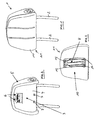
- FIG. 1 Shown is in FIG. 1 the headrest 1, which has on its underside two parallel arranged rods 2 for insertion in a known manner in receptacles in the upper region of a not illustrated backrest of a motor vehicle seat, for example, the driver's seat.
- the headrest 1 has a headrest impact body 3, which is formed by a front half 4 of the headrest impact body 3 and a rear half of the headrest impact body 3, wherein the rear half is not visible in the figures.
- the rear half of the headrest impact body 3 receives the rods 2.
- the headrest impact body 3 and a rear foam part 5 of the headrest 1 are trimmed with an unillustrated cover, which accordingly surrounds the headrest impact body 3 and the rear foam part 5.
- the front half 4 of the headrest impact body 3 has two receptacles 6 at the top and two receptacles 7 at the bottom. These form a support structure of the headrest impact body 3.
- the receptacles 6 and 7 serve to receive and fix a support structure 8 made of plastic, which accommodates a plastically deformable frame 9.
- the support structure 8 and the frame 9 are made of a plastically deformable Foam part 10 enclosed and form a total comfort element 11 for the headrest. This comfort element is additionally trimmed with a non-illustrated reference.
- the frame 9 has a substantially trapezoidal shape.
- the frame 9 has pieces of wire which represent rigid sections 12 and plastically deformable sections 13 in the region of the parallel sides of the trapezoid.
- the two sections are connected to each other in the region of their ends via connecting elements 14 which are formed as sleeves.
- the sections 12 and 13 are inserted into the connecting elements 14 and connected to these, for example by positive engagement.
- the support structure 8 engages them.
- the support structure encloses the plastically deformable portions 13 in the region of their ends and is provided with elastic upper front projections 15 and lower elastic projections 16 which can be inserted into the receptacles 6 and 7 of the front half 4 of the headrest impact body 3.
- the support structure 8 and, via this, the frame 9, thus the comfort element 11, can be connected to the headrest impact body.
- the plastically deformable sections 13 are designed in particular in the manner of a so-called flexible gooseneck. This consists of two mutually twisted coils, which can be arranged in any position to each other, so that the frame 9 can be arbitrarily bent in these areas.
- the frame 9 and thus the Comfort element 11 Due to the arbitrary deformability of the plastically deformable sections 13, the frame 9 and thus the Comfort element 11 to deform all possible spatial axes. This deformability can be assisted by the fact that the sections 12 of the frame 9, which in themselves are rigidly formed, have a relatively small thickness, so that they can be plastically deformed as desired by bending.
- the flexible design of the foam-coated frame 9 fundamentally enables an adjustability of the comfort element 11 in all three spatial axes X, Y and Z.
- the arrangement of frame 9 and support structure 8 can be produced in a particularly simple manner.
- Both the rigid sections 12 and the plastically deformable sections 13 of the frame 9 are placed in a mold corresponding to a desired starting position and then all the plastic parts to be connected to the sections 12 and 13 are produced in a molding process. This applies both to the plastic connecting elements 14 and to the support structure 8, which encloses the two plastically deformable sections 13.
- the headrest can be produced very simply, since the production of the frame 9 itself as well as the foaming thereof are based on known production methods. Due to the relatively simple design, the product, development and Investment costs for the realization of this headrest very low. Another advantage is based on the fact that the variable arrangement of the plastic deformation sections 13 in the frame 9 allows a very individual adaptation of the front foam part 10 and thus of the comfort element 11 to the head of the occupant. If the comfort element is designed plastically deformable even over its entire surface, maximum contouring is ensured.
Description
- Die Erfindung betrifft eine Kopfstütze mit einem Kopfstützenprallkörper und einem mit diesem verbindbaren sowie plastisch deformierbaren Komfortelement, wobei der Kopfstützenprallkörper mit einer Sitzlehne verbindbar ist und das Komfortelement der Anlage des Kopfes dient.
- Derartige Kopfstützen finden insbesondere in Verbindung mit Fahrzeugsitzen Verwendung, wie Autositzen, Zugsitzen, Flugzeugsitzen. Insbesondere bei Autositzen kommt den Kopfstützen die Funktion des Prallschutzes bei einem Crash und darüber hinaus eine Komfortfunktion zu. So ist man bestrebt, die Kopfstütze so anzuordnen, dass sich der Hinterkopf des Fahrzeuginsassen ergonomisch günstig an die Kopfstütze anlegen kann.
- Aus der
DE 101 96 653 T1 ist eine Kopfstütze der eingangs genannten Art bekannt, die dem Oberbegriff des Anspruchs 1 entspricht. Diese ist, zur Erhöhung des Komforts für die Person, mit dem plastisch deformierbaren Komfortelement versehen. Dieses als Schaumteil ausgebildete Komfortelement wird bevorzugt manuell verformt, um eine günstige Anlagefläche für den Kopf zu bieten. - Bei dieser bekannten Kopfstütze weist das plastisch deformierbare Komfortelement erste und zweite Seiten- oder Flügelabschnitte auf, zum stützenden Anlehnen an die Seitenabschnitte des Kopfes der Person, insbesondere wenn sie ruht. Diese Seitenabschnitte schließen mit einem diese verbindenden hinteren Element die Form eines U ein. Die gewünschte Form wird dem Komfortelement dadurch verliehen, dass dieses einen U-förmigen Rahmen aus biegsamen Material wie Aluminium, Kunststoff, Verbundstoff oder Stahl aufweist. Dieser Rahmen ist ausreichend steif, um laterale Krafteinwirkungen auf die Seitenabschnitte abzustützen.
- Nachteilig ist bei dieser Kopfstütze, dass das plastisch deformierbare Komfortelement nur um eine einzige Raumachse verformbar ist. Darunter werden alle Achsen verstanden, die im Wesentlichen parallel zueinander angeordnet sind. Dieses Komfortelement gemäß dem Stand der Technik kann nicht um beliebige Raumachsen verformt werden, insbesondere nicht um Raumachsen, die senkrecht zueinander stehen. Insofern ist die Verformbarkeit des plastisch deformierbaren Komfortelements deutlich eingeschränkt.
- Um den Fahrzeuginsassen einen optimalen Komfort zu bieten, ist eine Kopfstütze anzustreben, die eine umfassende Anlage des Kopfs, sowohl auf den Bereich des Hinterkopfs, als auch auf die seitlichen Bereiche des Kopfs bezogen, gewährleistet.
- Es ist Aufgabe der vorliegenden Erfindung, eine Kopfstütze der eingangs genannten Art so weiterzubilden, die die vorgenannten Nachteile des Standes der Technik vermeidet und eine ergonomisch optimale Anlage des Kopfes des Insassen an der Kopfstütze, konkret dem plastischen deformierbaren Komfortelement, gewährleistet ist.
- Gelöst wird die Aufgabe bei einer Kopfstütze der eingangs genannten Art mit den Merkmalen des Anspruchs 1.
- Bei der erfindungsgemäßen Kopfstütze besteht die Möglichkeit, das Komfortelement beliebig der Kontur des Kopfes des Insassen im Bereich des Hinterkopfes und der Seiten des Kopfes anzupassen. Dies ist auf Grund der Verformbarkeit des Komfortelements um verschiedene Raumachsen möglich. Es ist nicht nur die Verformbarkeit des Komfortelements um die Raumachse, die im Wesentlichen vertikal verläuft und damit die Möglichkeit eröffnet, Seitenabschnitte des Komfortelements an den Kopf des Insassen heranzuführen, gewährleistet, sondern es kann das Komfortelement um eine im Wesentlichen senkrecht zu dieser Raumachse stehende Raumachse gleichfalls verformt werden, beispielsweise um eine im Wesentlichen horizontale Raumachse. Schließlich besteht grundsätzlich auch die Möglichkeit, das Komfortelement in der Dritten der drei Raumachsen zu verformen.
- So ist gemäß einer bevorzugten Ausführungsform vorgesehen, dass das Komfortelement einen plastisch verformbaren Rahmen und ein plastisch deformierbares Schaumteil aufweist, wobei das Schaumteil um den Rahmen geschäumt ist und diesen somit aufnimmt. Der Rahmen gibt somit, gemäß seiner plastisch deformierten Gestalt, die plastische Gestalt des Schaumteils vor. Der Fahrzeuginsasse muss nur das Komfortelement ergreifen und verformen, wobei der Rahmen und das Schaumteil entsprechend verformt werden und in der gewünschten verformten Position verbleiben.
- Der plastisch verformbare Rahmen ist beispielsweise durch starre Teilstücke und diese verbindende plastische Deformationselemente gebildet. Unter diesem Aspekt ist es vorteilhaft, die starren Teilstücke als Drahtstücke auszubilden, wobei jedes plastische Deformationselement auf einander abgewandten Enden ein starres Teilstück aufnimmt. Es ist genauso denkbar, den Rahmen als Drahtrahmen auszubilden. In diesem Fall ist die Stärke des Drahtes so zu wählen, dass die gewünschte Deformation des Schaumteils und damit des Komfortelemente durch Biegen des Drahtrahmens zu Stande kommt. Demnach ist der Rahmen insgesamt aus plastisch deformierbarem Material gebildet. Das Komfortelement ist vorzugsweise unmittelbar über den Rahmen oder über eine diesen aufnehmende Tragstruktur im Kopfstützenprallkörper gelagert. In diesem Fall ist die Tragstruktur gleichfalls Bestandteil des Komfortelements.
- Die Verbindung des Komfortelements, insbesondere dessen Rahmen, kann auf unterschiedliche Art und Weise mit dem Kopfstützenprallkörper erfolgen. Die Verbindung geschieht vorzugsweise mittels einer Klipsverbindung, die es demzufolge gestattet, das Komfortelement unkompliziert mit dem Kopfstützenprallkörper zu verbinden und auch wieder von diesem zu lösen.
- Der Kopfstützenprallkörper und das plastisch deformierbare Komfortelement sind insbesondere als unabhängige Baueinheiten zu sehen, wobei die Kopfstütze durchaus ohne das plastisch deformierbare Komfortelement, somit auf Grund des Kopfstützenprallkörpers, funktionsfähig ist. Das plastisch deformierbare Komfortelement bildet in aller Regel einen notwendigen Bestandteil der Kopfstütze, kann aber durchaus auch als Zubehörteil nachgekauft werden. In diesem Fall ist es nur erforderlich, den Kopfstützenprallkörper mit einer Aufnahme zum Befestigen des Komfortelements an diesem auszustatten.
- Auf Grund der separaten Baueinheiten, demnach der unabhängigen Funktionalität des Komfortelements, ist dieses insbesondere mit einem eigenständigen Bezug umgeben. Entsprechendes gilt für den Kopfstützenprallkörper. Dieser bildet aber vorzugsweise mit einem hinteren Schaumteil der Kopfstütze eine Baueinheit. Dieses hintere Schaumteil deformiert sich bei einem Aufprall eines hinteren Insassen. Die Einheit von Kopfstützenprallkörper und hinterem Schaumteil ist mittels eines separaten Bezuges getrimmt.
- Es ist insbesondere vorgesehen, dass der Kopfstützenprallkörper ohne Bezug ausgebildet ist, und das Komfortelement unmittelbar mittels deren Tragstruktur am Kopfstützenprallkörper befestigbar ist. Insbesondere eine derart gestaltete Kopfstütze lässt sich preislich besonders günstig herstellen, bei einfacher Montierbarkeit des Komfortelements und optisch ansprechendem Gesamteindruck.
- Die erfindungsgemäße Kopfstütze ermöglicht demnach dem Insassen eine optimale Anlage seines Kopfes am Komfortelement in seiner Eigenschaft als Kopfstützenpolster. Hierdurch wird ein besserer Komfort für den Insassen erzielt, da der Kopf die Seitenbeschleunigungen besser aufnehmen kann. Ferner wird dem Insassen eine optimale Relaxposition angeboten. Die Kopfstütze kann baulich äußert einfach gestaltet werden, weil auf jegliche Art von Gelenken verzichtet werden kann. Dadurch, dass das Komfortelement um verschiedene Raumachsen verformbar ist, lässt sich die Form des Polsterträgers optimal an unterschiedliche Kopfkonturen anpassen. Das plastisch deformierbare Komfortelement kann als sehr einfache Konstruktion ausgeführt werden, mit der Folge niedriger Entwicklungs- und Produktkosten.
- In den Figuren ist eine bevorzugte Ausführungsform der Erfindung beschrieben, ohne auf diese beschränkt zu sein. Es zeigt:
- Figur 1
- eine räumliche Ansicht der erfindungsgemäßen Kopfstütze, komplett montiert, von vorne gesehen,
- Figur 2
- die in
Figur 1 gezeigte Kopfstütze ohne das Komfortelement, von vorne gesehen, - Figur 3
- das Komfortelement der Kopfstütze, von hinten gesehen,
- Figur 4
- die Anordnung einer vorderen Hälfte des in
Figur 2 gezeigten Kopfstützenprallkörpers und der in diesen eingesteckten Tragstruktur mit Rahmen, wobei Tragstruktur und Rahmen Bestandteil des Komfortelements bilden, von vorne gesehen, - Figur 5
- die in
Figur 4 veranschaulichten Teile in einer Draufsicht gesehen, - Figur 6
- die in den
Figuren 4 und 5 veranschaulichten Teile in einer Seitenansicht gesehen und - Figur 7
- die in den
Figuren 4 bis 6 gezeigten Teile in einer räumlichen Ansicht, schräg von vorne gesehen. - Gezeigt ist in
Figur 1 die Kopfstütze 1, die an ihrer Unterseite zwei parallel angeordnete Stangen 2 zum Einstecken in bekannter Art und Weise in Aufnahmen im oberen Bereich einer nicht veranschaulichten Rückenlehne eines Kraftfahrzeugsitzes, beispielsweise des Fahrersitzes, aufweist. - Die Kopfstütze 1 weist einen Kopfstützenprallkörper 3 auf, der durch eine vordere Hälfte 4 des Kopfstützenprallkörpers 3 und eine hintere Hälfte des Kopfstützenprallkörpers 3 gebildet ist, wobei die hintere Hälfte in den Figuren nicht einsehbar ist. Die hintere Hälfte des Kopfstützenprallkörpers 3 nimmt die Stangen 2 auf.
- Der Kopfstützenprallkörper 3 und ein hinteres Schaumteil 5 der Kopfstütze 1 werden mit einem nicht veranschaulichten Bezug getrimmt, der demnach den Kopfstützenprallkörper 3 und das hintere Schaumteil 5 umgibt.
- Weiterhin weist die vordere Hälfte 4 des Kopfstützenprallkörpers 3 oben zwei Aufnahmen 6 auf, sowie unten zwei Aufnahmen 7 auf. Diese bilden eine Tragstruktur des Kopfstützenprallkörpers 3. Die Aufnahmen 6 und 7 dienen der Aufnahme und Fixierung einer Tragstruktur 8 aus Kunststoff, die einen plastisch deformierbaren Rahmen 9 aufnimmt. Die Tragstruktur 8 und der Rahmen 9 werden von einem plastisch deformierbaren Schaumteil 10 umschlossen und bilden insgesamt ein Komfortelement 11 für die Kopfstütze. Dieses Komfortelement ist zusätzlich mit einem nicht veranschaulichten Bezug getrimmt.
- Wesentlich ist bei dem Komfortelement 11 der umschäumte Rahmen 9. Der Darstellung der
Figuren 4 bis 7 ist zu entnehmen, dass der Rahmen 9 im Wesentlichen Trapezform aufweist. Der Rahmen 9 weist im Bereich der nicht parallelen Seiten des Trapezes Drahtstücke auf, die starre Teilstücke 12 darstellen und im Bereich der parallelen Seiten des Trapezes plastisch verformbare Teilstücke 13 auf. Die beiden Teilstücke sind im Bereich deren Enden über Verbindungselemente 14, die als Hülsen ausgebildet sind, miteinander verbunden. Die Teilstücke 12 und 13 sind in die Verbindungselemente 14 eingesteckt und mit diesen beispielsweise durch Formschluss verbunden. In etwa auf der halben Länge des jeweils plastisch umformbaren Teilstücks 13 greift die Tragstruktur 8 an diesen an. Die Tragstruktur umschließt im Bereich ihrer Enden die plastisch verformbaren Teilstücke 13 und ist mit elastischen oberen vorderen Vorsprüngen 15 und unteren elastischen Vorsprüngen 16 versehen, die in die Aufnahmen 6 bzw. 7 der vorderen Hälfte 4 des Kopfstützenprallkörpers 3 einsteckbar sind. Hierdurch lässt sich die Tragstruktur 8 und über diese der Rahmen 9, somit das Komfortelement 11, mit dem Kopfstützenprallkörper verbinden. - Die plastisch verformbaren Teilstücke 13 sind insbesondere in Art eines so genannten flexiblen Schwanenhalses ausgebildet. Dieser besteht aus zwei ineinander verdrillten Wendeln, die in beliebigen Positionen zueinander anordbar sind, womit sich der Rahmen 9 in diesen Bereichen beliebig biegen lässt.
- Auf Grund der beliebigen Umformbarkeit der plastisch verformbaren Teilstücke 13 lässt sich der Rahmen 9 und damit das Komfortelement 11 um alle möglichen Raumachsen verformen. Unterstützt werden kann diese Verformbarkeit dadurch, dass die an und für sich starr ausgebildeten Teilstücke 12 des Rahmens 9 eine relativ geringe Stärke besitzen, sodass sie durch Biegen beliebig plastisch verformt werden können.
- Die flexible Gestaltung des umschäumten Rahmens 9 ermöglicht grundsätzlich eine Verstellbarkeit des Komfortelements 11 in allen drei Raumachsen X, Y und Z.
- Insbesondere die Anordnung von Rahmen 9 und Tragstruktur 8 lässt sich auf besonders einfache Art und Weise herstellen. Es werden sowohl die starren Teilstücke 12 als auch die plastisch verformbaren Teilstücke 13 des Rahmens 9 entsprechend einer gewünschten Ausgangsposition in eine Form gelegt und dann alle Kunststoffteile, die mit den Teilstücken 12 und 13 zu verbinden sind, in einem Formvorgang hergestellt. Dies gilt sowohl für die aus Kunststoff bestehenden Verbindungselemente 14 als auch für die Tragstruktur 8, die die beiden plastisch umformbaren Teilstücke 13 umschließt.
- Vorstehende Ausführungen verdeutlichen, dass die Kopfstütze sehr einfach hergestellt werden kann, da die Fertigung des Rahmens 9 selbst sowie das Einschäumen desselben auf bekannten Fertigungsverfahren beruhen. Auf Grund der relativ einfach gehaltenen Konstruktion sind die Produkt-, Entwicklungs- und Investmentkosten für die Realisation dieser Kopfstütze sehr gering. Ein weiterer Vorteile beruht darauf, dass die variable Anordnung der plastischen Deformationsteilstücke 13 im Rahmen 9 eine sehr individuelle Anpassung des vorderen Schaumteils 10 und damit des Komfortelements 11 an den Kopf des Insassen ermöglicht. Ist das Komfortelement sogar in seiner gesamten Fläche plastisch verformbar gestaltet, ist maximale Konturierbarkeit gewährleistet.
-
- Kopfstütze
- 1
- Stange
- 2
- Kopfstützenprallkörper
- 3
- vordere Hälfte
- 4
- hinteres Schaumteil
- 5
- Aufnahme
- 6
- Aufnahme
- 7
- Tragstruktur
- 8
- Rahmen
- 9
- vorderes Schaumteil
- 10
- Komfortelement
- 11
- starres Teilstück
- 12
- plastisch verformbares Teilstück
- 13
- Verbindungselement
- 14
- Vorsprung
- 15
- Vorsprung
- 16
Claims (8)
- Kopfstütze (1) mit einem Kopfstützenprallkörper (3) und einem mit diesem verbindbaren sowie plastisch deformierbaren Komfortelement (11), wobei der Kopfstützenprallkörper (3) mit einer Sitzlehne verbindbar ist oder eine Einheit mit dieser bildet, und das Komfortelement (11) der Anlage des Kopfes dient, wobei das Komfortelement (11) um verschiedenen Raumachsen verformbar ist, dadurch gekennzeichnet, dass das Komfortelement (11) einen plastisch verformbaren Rahmen (9) aufweist, wobei der Rahmen (9) durch starre Teilstücke (12) und diese verbindende plastisch und um verschiedene Raumachsen beliebig umformbare Teilstücke (13) gebildet ist.
- Kopfstütze nach Anspruch 1, dadurch gekennzeichnet, dass der Rahmen (9) im Wesentlichen rechteckig oder trapezförmig ist.
- Kopfstütze nach Anspruch 1 oder 2, dadurch gekennzeichnet, dass der Rahmen (9) unmittelbar oder über eine diese aufnehmende, Bestandteil des Komfortelements bildende Tragstruktur (8) im Kopfstützenprallkörper (3) gelagert ist.
- Kopfstütze nach einem der Ansprüche 1 bis 3, dadurch gekennzeichnet, dass das Komfortelement (11), insbesondere dessen Rahmen (9) oder dessen Tragstruktur (8), über eine Klipsverbindung mit dem Kopfstützenprallkörper (3) verbindbar ist.
- Kopfstütze nach einem der Ansprüche 1 bis 4, dadurch gekennzeichnet, dass das Komfortelement (11) mit einem Bezug umgeben ist.
- Kopfstütze nach einem der Ansprüche 1 bis 5, dadurch gekennzeichnet, dass das Komfortelement (11) ein plastisch umforbares Schaumteil (10) und einen von diesem aufgenommenen plastisch verformbaren Rahmen (9) aufweist.
- Kopfstütze nach einem der Ansprüche 1 bis 6, dadurch gekennzeichnet, dass das Komfortelement (11) mit einem eigenständigen Bezug getrimmt ist.
- Kopfstütze nach einem der Ansprüche 1 bis 7, dadurch gekennzeichnet, dass der Kopfstützenprallkörper (3) ohne Bezug ausgebildet ist und das Komfortelement (11) unmittelbar an einer Tragstruktur (6, 6) des Kopfstützenprallkörpers (3) befestigbar ist.
Applications Claiming Priority (1)
| Application Number | Priority Date | Filing Date | Title |
|---|---|---|---|
| DE102005060912A DE102005060912A1 (de) | 2005-12-20 | 2005-12-20 | Kopfstütze mit plastisch deformierbarem Komfortelement |
Publications (2)
| Publication Number | Publication Date |
|---|---|
| EP1800943A1 EP1800943A1 (de) | 2007-06-27 |
| EP1800943B1 true EP1800943B1 (de) | 2009-02-18 |
Family
ID=37895789
Family Applications (1)
| Application Number | Title | Priority Date | Filing Date |
|---|---|---|---|
| EP06025412A Not-in-force EP1800943B1 (de) | 2005-12-20 | 2006-12-08 | Kopfstütze mit plastisch deformierbarem Komfortelement |
Country Status (3)
| Country | Link |
|---|---|
| EP (1) | EP1800943B1 (de) |
| AT (1) | ATE423036T1 (de) |
| DE (2) | DE102005060912A1 (de) |
Families Citing this family (1)
| Publication number | Priority date | Publication date | Assignee | Title |
|---|---|---|---|---|
| DE102009004770A1 (de) | 2009-01-15 | 2009-08-27 | Daimler Ag | Kraftfahrzeugsitz mit ergonomisch geformter Rückenlehne |
Family Cites Families (8)
| Publication number | Priority date | Publication date | Assignee | Title |
|---|---|---|---|---|
| DE2152202C3 (de) * | 1971-10-20 | 1981-07-16 | Adam Opel AG, 6090 Rüsselsheim | Kopfstütze für Kraftfahrzeugsitze |
| DE2430572C3 (de) * | 1974-06-26 | 1978-07-06 | Ford-Werke Ag, 5000 Koeln | Kopfstütze für Fahrzeugsitze |
| DE9312512U1 (de) * | 1993-08-20 | 1995-01-05 | Baldering Bertold | Polster für Kopfstützen von Kraftfahrzeugen |
| NL9400588A (nl) * | 1994-04-13 | 1995-11-01 | Johannes Theodorus Marie Rasen | Stoel. |
| JP3695161B2 (ja) * | 1998-07-22 | 2005-09-14 | 三菱自動車工業株式会社 | 自動車用ヘッドレスト構造 |
| US6648416B2 (en) * | 1998-08-13 | 2003-11-18 | Richard W. O'Connor | Headrest |
| DE19958797C1 (de) * | 1999-12-07 | 2001-05-03 | Faure Bertrand Sitztech Gmbh | Stützeinrichtung für Kopf und/oder Nacken |
| DE10318927B4 (de) * | 2003-04-26 | 2005-05-19 | Daimlerchrysler Ag | Kopfstütze in Form eines mehrteiligen Netzes |
-
2005
- 2005-12-20 DE DE102005060912A patent/DE102005060912A1/de not_active Withdrawn
-
2006
- 2006-12-08 AT AT06025412T patent/ATE423036T1/de not_active IP Right Cessation
- 2006-12-08 DE DE502006002873T patent/DE502006002873D1/de active Active
- 2006-12-08 EP EP06025412A patent/EP1800943B1/de not_active Not-in-force
Also Published As
| Publication number | Publication date |
|---|---|
| DE102005060912A1 (de) | 2007-06-28 |
| EP1800943A1 (de) | 2007-06-27 |
| ATE423036T1 (de) | 2009-03-15 |
| DE502006002873D1 (de) | 2009-04-02 |
Similar Documents
| Publication | Publication Date | Title |
|---|---|---|
| DE10334595B4 (de) | Sitzanordnung für Fahrzeuge | |
| DE10219764B4 (de) | Klappbare Fahrzeugbordwand mit daran befestigten Sitzkomponenten | |
| DE19845730B4 (de) | Polsterträger | |
| EP0958972B1 (de) | Kopfstütze mit Gassackmodul | |
| DE3841532A1 (de) | Rueckenlehnen-tragstruktur fuer einen fahrzeugsitz und fahrzeugsitz-rueckenlehne mit dieser rueckenlehnen-tragstruktur | |
| DE102014220740B4 (de) | Modularer verbundrahmen für eine hintere sitzkonstruktion | |
| DE102005017061A1 (de) | Fahrzeugsitzrahmen | |
| EP3250400B1 (de) | Leichtbausitz für fahrzeuge | |
| DE102012204813B4 (de) | Fahrzeugsitz mit einer integrierten Kopfstütze und Verfahren zur Herstellung eines Fahrzeugsitzes | |
| EP1800943B1 (de) | Kopfstütze mit plastisch deformierbarem Komfortelement | |
| EP2783910A1 (de) | Fahrzeugsitz mit einer integrierten Kopfstütze und Verfahren zur Herstellung eines Fahrzeugsitzes | |
| DE3928884C2 (de) | ||
| DE102013017408A1 (de) | Kraftfahrzeugrückenlehnenstruktur | |
| EP2837529A1 (de) | Verfahren zur Umrüstung eines Fahrzeugsitzes | |
| DE2238216B2 (de) | Sitzrahmen | |
| DE102004027900A1 (de) | Fahrzeugsitz | |
| EP1477360A2 (de) | Rückenlehne | |
| DE4232364A1 (de) | Schalensitz für Fahrzeuge, insbesondere für Personenkraftwagen | |
| DE102009021654A1 (de) | Fahrzeugsitz | |
| DE102004014420A1 (de) | Rohrrahmen für einen Sitz | |
| DE102005002689B3 (de) | Polsterelement | |
| DE102007050092A1 (de) | Fahrzeugsitz sowie Modulsystem und Verfahren zu dessen Herstellung | |
| DE19520583C2 (de) | Sitzlehne für Fahrzeugsitze | |
| DE102005021906B3 (de) | Sitz für ein Kraftfahrzeug | |
| DE2845488A1 (de) | Fahrzeugsitz |
Legal Events
| Date | Code | Title | Description |
|---|---|---|---|
| PUAI | Public reference made under article 153(3) epc to a published international application that has entered the european phase |
Free format text: ORIGINAL CODE: 0009012 |
|
| AK | Designated contracting states |
Kind code of ref document: A1 Designated state(s): AT BE BG CH CY CZ DE DK EE ES FI FR GB GR HU IE IS IT LI LT LU LV MC NL PL PT RO SE SI SK TR |
|
| AX | Request for extension of the european patent |
Extension state: AL BA HR MK YU |
|
| 17P | Request for examination filed |
Effective date: 20071227 |
|
| AKX | Designation fees paid |
Designated state(s): AT BE BG CH CY CZ DE DK EE ES FI FR GB GR HU IE IS IT LI LT LU LV MC NL PL PT RO SE SI SK TR |
|
| 17Q | First examination report despatched |
Effective date: 20080310 |
|
| GRAP | Despatch of communication of intention to grant a patent |
Free format text: ORIGINAL CODE: EPIDOSNIGR1 |
|
| GRAS | Grant fee paid |
Free format text: ORIGINAL CODE: EPIDOSNIGR3 |
|
| GRAA | (expected) grant |
Free format text: ORIGINAL CODE: 0009210 |
|
| AK | Designated contracting states |
Kind code of ref document: B1 Designated state(s): AT BE BG CH CY CZ DE DK EE ES FI FR GB GR HU IE IS IT LI LT LU LV MC NL PL PT RO SE SI SK TR |
|
| REG | Reference to a national code |
Ref country code: GB Ref legal event code: FG4D Free format text: NOT ENGLISH |
|
| REG | Reference to a national code |
Ref country code: CH Ref legal event code: EP |
|
| REG | Reference to a national code |
Ref country code: IE Ref legal event code: FG4D Free format text: LANGUAGE OF EP DOCUMENT: GERMAN |
|
| REF | Corresponds to: |
Ref document number: 502006002873 Country of ref document: DE Date of ref document: 20090402 Kind code of ref document: P |
|
| PG25 | Lapsed in a contracting state [announced via postgrant information from national office to epo] |
Ref country code: SI Free format text: LAPSE BECAUSE OF FAILURE TO SUBMIT A TRANSLATION OF THE DESCRIPTION OR TO PAY THE FEE WITHIN THE PRESCRIBED TIME-LIMIT Effective date: 20090218 Ref country code: FI Free format text: LAPSE BECAUSE OF FAILURE TO SUBMIT A TRANSLATION OF THE DESCRIPTION OR TO PAY THE FEE WITHIN THE PRESCRIBED TIME-LIMIT Effective date: 20090218 Ref country code: LT Free format text: LAPSE BECAUSE OF FAILURE TO SUBMIT A TRANSLATION OF THE DESCRIPTION OR TO PAY THE FEE WITHIN THE PRESCRIBED TIME-LIMIT Effective date: 20090218 Ref country code: NL Free format text: LAPSE BECAUSE OF FAILURE TO SUBMIT A TRANSLATION OF THE DESCRIPTION OR TO PAY THE FEE WITHIN THE PRESCRIBED TIME-LIMIT Effective date: 20090218 Ref country code: ES Free format text: LAPSE BECAUSE OF FAILURE TO SUBMIT A TRANSLATION OF THE DESCRIPTION OR TO PAY THE FEE WITHIN THE PRESCRIBED TIME-LIMIT Effective date: 20090529 |
|
| NLV1 | Nl: lapsed or annulled due to failure to fulfill the requirements of art. 29p and 29m of the patents act | ||
| PG25 | Lapsed in a contracting state [announced via postgrant information from national office to epo] |
Ref country code: IS Free format text: LAPSE BECAUSE OF FAILURE TO SUBMIT A TRANSLATION OF THE DESCRIPTION OR TO PAY THE FEE WITHIN THE PRESCRIBED TIME-LIMIT Effective date: 20090618 Ref country code: LV Free format text: LAPSE BECAUSE OF FAILURE TO SUBMIT A TRANSLATION OF THE DESCRIPTION OR TO PAY THE FEE WITHIN THE PRESCRIBED TIME-LIMIT Effective date: 20090218 Ref country code: PL Free format text: LAPSE BECAUSE OF FAILURE TO SUBMIT A TRANSLATION OF THE DESCRIPTION OR TO PAY THE FEE WITHIN THE PRESCRIBED TIME-LIMIT Effective date: 20090218 Ref country code: SE Free format text: LAPSE BECAUSE OF FAILURE TO SUBMIT A TRANSLATION OF THE DESCRIPTION OR TO PAY THE FEE WITHIN THE PRESCRIBED TIME-LIMIT Effective date: 20090518 |
|
| REG | Reference to a national code |
Ref country code: IE Ref legal event code: FD4D |
|
| PG25 | Lapsed in a contracting state [announced via postgrant information from national office to epo] |
Ref country code: PT Free format text: LAPSE BECAUSE OF FAILURE TO SUBMIT A TRANSLATION OF THE DESCRIPTION OR TO PAY THE FEE WITHIN THE PRESCRIBED TIME-LIMIT Effective date: 20090727 Ref country code: IE Free format text: LAPSE BECAUSE OF FAILURE TO SUBMIT A TRANSLATION OF THE DESCRIPTION OR TO PAY THE FEE WITHIN THE PRESCRIBED TIME-LIMIT Effective date: 20090218 Ref country code: CZ Free format text: LAPSE BECAUSE OF FAILURE TO SUBMIT A TRANSLATION OF THE DESCRIPTION OR TO PAY THE FEE WITHIN THE PRESCRIBED TIME-LIMIT Effective date: 20090218 Ref country code: DK Free format text: LAPSE BECAUSE OF FAILURE TO SUBMIT A TRANSLATION OF THE DESCRIPTION OR TO PAY THE FEE WITHIN THE PRESCRIBED TIME-LIMIT Effective date: 20090218 Ref country code: EE Free format text: LAPSE BECAUSE OF FAILURE TO SUBMIT A TRANSLATION OF THE DESCRIPTION OR TO PAY THE FEE WITHIN THE PRESCRIBED TIME-LIMIT Effective date: 20090218 |
|
| REG | Reference to a national code |
Ref country code: GB Ref legal event code: 732E Free format text: REGISTERED BETWEEN 20091029 AND 20091104 |
|
| PG25 | Lapsed in a contracting state [announced via postgrant information from national office to epo] |
Ref country code: SK Free format text: LAPSE BECAUSE OF FAILURE TO SUBMIT A TRANSLATION OF THE DESCRIPTION OR TO PAY THE FEE WITHIN THE PRESCRIBED TIME-LIMIT Effective date: 20090218 Ref country code: RO Free format text: LAPSE BECAUSE OF FAILURE TO SUBMIT A TRANSLATION OF THE DESCRIPTION OR TO PAY THE FEE WITHIN THE PRESCRIBED TIME-LIMIT Effective date: 20090218 |
|
| REG | Reference to a national code |
Ref country code: GB Ref legal event code: 732E Free format text: REGISTERED BETWEEN 20091105 AND 20091111 |
|
| PLBE | No opposition filed within time limit |
Free format text: ORIGINAL CODE: 0009261 |
|
| STAA | Information on the status of an ep patent application or granted ep patent |
Free format text: STATUS: NO OPPOSITION FILED WITHIN TIME LIMIT |
|
| 26N | No opposition filed |
Effective date: 20091119 |
|
| PG25 | Lapsed in a contracting state [announced via postgrant information from national office to epo] |
Ref country code: BG Free format text: LAPSE BECAUSE OF FAILURE TO SUBMIT A TRANSLATION OF THE DESCRIPTION OR TO PAY THE FEE WITHIN THE PRESCRIBED TIME-LIMIT Effective date: 20090518 |
|
| BERE | Be: lapsed |
Owner name: GM GLOBAL TECHNOLOGY OPERATIONS, INC. Effective date: 20091231 |
|
| PG25 | Lapsed in a contracting state [announced via postgrant information from national office to epo] |
Ref country code: MC Free format text: LAPSE BECAUSE OF NON-PAYMENT OF DUE FEES Effective date: 20100701 |
|
| PG25 | Lapsed in a contracting state [announced via postgrant information from national office to epo] |
Ref country code: BE Free format text: LAPSE BECAUSE OF NON-PAYMENT OF DUE FEES Effective date: 20091231 Ref country code: GR Free format text: LAPSE BECAUSE OF FAILURE TO SUBMIT A TRANSLATION OF THE DESCRIPTION OR TO PAY THE FEE WITHIN THE PRESCRIBED TIME-LIMIT Effective date: 20090519 |
|
| PG25 | Lapsed in a contracting state [announced via postgrant information from national office to epo] |
Ref country code: IT Free format text: LAPSE BECAUSE OF FAILURE TO SUBMIT A TRANSLATION OF THE DESCRIPTION OR TO PAY THE FEE WITHIN THE PRESCRIBED TIME-LIMIT Effective date: 20090218 |
|
| PG25 | Lapsed in a contracting state [announced via postgrant information from national office to epo] |
Ref country code: LU Free format text: LAPSE BECAUSE OF NON-PAYMENT OF DUE FEES Effective date: 20091208 |
|
| REG | Reference to a national code |
Ref country code: DE Ref legal event code: R081 Ref document number: 502006002873 Country of ref document: DE Owner name: GM GLOBAL TECHNOLOGY OPERATIONS LLC (N. D. GES, US Free format text: FORMER OWNER: GM GLOBAL TECHNOLOGY OPERATIONS, INC., DETROIT, MICH., US Effective date: 20110323 |
|
| PG25 | Lapsed in a contracting state [announced via postgrant information from national office to epo] |
Ref country code: AT Free format text: LAPSE BECAUSE OF NON-PAYMENT OF DUE FEES Effective date: 20091208 |
|
| PG25 | Lapsed in a contracting state [announced via postgrant information from national office to epo] |
Ref country code: HU Free format text: LAPSE BECAUSE OF FAILURE TO SUBMIT A TRANSLATION OF THE DESCRIPTION OR TO PAY THE FEE WITHIN THE PRESCRIBED TIME-LIMIT Effective date: 20090819 |
|
| REG | Reference to a national code |
Ref country code: CH Ref legal event code: PL |
|
| PG25 | Lapsed in a contracting state [announced via postgrant information from national office to epo] |
Ref country code: TR Free format text: LAPSE BECAUSE OF FAILURE TO SUBMIT A TRANSLATION OF THE DESCRIPTION OR TO PAY THE FEE WITHIN THE PRESCRIBED TIME-LIMIT Effective date: 20090218 |
|
| PG25 | Lapsed in a contracting state [announced via postgrant information from national office to epo] |
Ref country code: CY Free format text: LAPSE BECAUSE OF FAILURE TO SUBMIT A TRANSLATION OF THE DESCRIPTION OR TO PAY THE FEE WITHIN THE PRESCRIBED TIME-LIMIT Effective date: 20090218 |
|
| PG25 | Lapsed in a contracting state [announced via postgrant information from national office to epo] |
Ref country code: LI Free format text: LAPSE BECAUSE OF NON-PAYMENT OF DUE FEES Effective date: 20101231 Ref country code: CH Free format text: LAPSE BECAUSE OF NON-PAYMENT OF DUE FEES Effective date: 20101231 |
|
| PGFP | Annual fee paid to national office [announced via postgrant information from national office to epo] |
Ref country code: DE Payment date: 20121205 Year of fee payment: 7 |
|
| PGFP | Annual fee paid to national office [announced via postgrant information from national office to epo] |
Ref country code: GB Payment date: 20121205 Year of fee payment: 7 |
|
| PGFP | Annual fee paid to national office [announced via postgrant information from national office to epo] |
Ref country code: FR Payment date: 20130107 Year of fee payment: 7 |
|
| REG | Reference to a national code |
Ref country code: DE Ref legal event code: R119 Ref document number: 502006002873 Country of ref document: DE |
|
| GBPC | Gb: european patent ceased through non-payment of renewal fee |
Effective date: 20131208 |
|
| REG | Reference to a national code |
Ref country code: DE Ref legal event code: R119 Ref document number: 502006002873 Country of ref document: DE Effective date: 20140701 |
|
| REG | Reference to a national code |
Ref country code: FR Ref legal event code: ST Effective date: 20140829 |
|
| PG25 | Lapsed in a contracting state [announced via postgrant information from national office to epo] |
Ref country code: DE Free format text: LAPSE BECAUSE OF NON-PAYMENT OF DUE FEES Effective date: 20140701 |
|
| PG25 | Lapsed in a contracting state [announced via postgrant information from national office to epo] |
Ref country code: GB Free format text: LAPSE BECAUSE OF NON-PAYMENT OF DUE FEES Effective date: 20131208 Ref country code: FR Free format text: LAPSE BECAUSE OF NON-PAYMENT OF DUE FEES Effective date: 20131231 |