EP1791584B1 - Inhalator für pulverförmige, insbesondere medizinische substanzen - Google Patents
Inhalator für pulverförmige, insbesondere medizinische substanzen Download PDFInfo
- Publication number
- EP1791584B1 EP1791584B1 EP05786868.9A EP05786868A EP1791584B1 EP 1791584 B1 EP1791584 B1 EP 1791584B1 EP 05786868 A EP05786868 A EP 05786868A EP 1791584 B1 EP1791584 B1 EP 1791584B1
- Authority
- EP
- European Patent Office
- Prior art keywords
- plunger
- substance
- chamber
- inhaler
- suction air
- Prior art date
- Legal status (The legal status is an assumption and is not a legal conclusion. Google has not performed a legal analysis and makes no representation as to the accuracy of the status listed.)
- Expired - Lifetime
Links
Images


Classifications
-
- A—HUMAN NECESSITIES
- A61—MEDICAL OR VETERINARY SCIENCE; HYGIENE
- A61M—DEVICES FOR INTRODUCING MEDIA INTO, OR ONTO, THE BODY; DEVICES FOR TRANSDUCING BODY MEDIA OR FOR TAKING MEDIA FROM THE BODY; DEVICES FOR PRODUCING OR ENDING SLEEP OR STUPOR
- A61M15/00—Inhalators
-
- A—HUMAN NECESSITIES
- A61—MEDICAL OR VETERINARY SCIENCE; HYGIENE
- A61M—DEVICES FOR INTRODUCING MEDIA INTO, OR ONTO, THE BODY; DEVICES FOR TRANSDUCING BODY MEDIA OR FOR TAKING MEDIA FROM THE BODY; DEVICES FOR PRODUCING OR ENDING SLEEP OR STUPOR
- A61M15/00—Inhalators
- A61M15/0001—Details of inhalators; Constructional features thereof
- A61M15/0005—Details of inhalators; Constructional features thereof with means for agitating the medicament
- A61M15/0006—Details of inhalators; Constructional features thereof with means for agitating the medicament using rotating means
-
- A—HUMAN NECESSITIES
- A61—MEDICAL OR VETERINARY SCIENCE; HYGIENE
- A61M—DEVICES FOR INTRODUCING MEDIA INTO, OR ONTO, THE BODY; DEVICES FOR TRANSDUCING BODY MEDIA OR FOR TAKING MEDIA FROM THE BODY; DEVICES FOR PRODUCING OR ENDING SLEEP OR STUPOR
- A61M15/00—Inhalators
- A61M15/0001—Details of inhalators; Constructional features thereof
- A61M15/0005—Details of inhalators; Constructional features thereof with means for agitating the medicament
-
- A—HUMAN NECESSITIES
- A61—MEDICAL OR VETERINARY SCIENCE; HYGIENE
- A61M—DEVICES FOR INTRODUCING MEDIA INTO, OR ONTO, THE BODY; DEVICES FOR TRANSDUCING BODY MEDIA OR FOR TAKING MEDIA FROM THE BODY; DEVICES FOR PRODUCING OR ENDING SLEEP OR STUPOR
- A61M15/00—Inhalators
- A61M15/0001—Details of inhalators; Constructional features thereof
- A61M15/002—Details of inhalators; Constructional features thereof with air flow regulating means
-
- A—HUMAN NECESSITIES
- A61—MEDICAL OR VETERINARY SCIENCE; HYGIENE
- A61M—DEVICES FOR INTRODUCING MEDIA INTO, OR ONTO, THE BODY; DEVICES FOR TRANSDUCING BODY MEDIA OR FOR TAKING MEDIA FROM THE BODY; DEVICES FOR PRODUCING OR ENDING SLEEP OR STUPOR
- A61M15/00—Inhalators
- A61M15/0001—Details of inhalators; Constructional features thereof
- A61M15/0021—Mouthpieces therefor
- A61M15/0025—Mouthpieces therefor with caps
-
- A—HUMAN NECESSITIES
- A61—MEDICAL OR VETERINARY SCIENCE; HYGIENE
- A61M—DEVICES FOR INTRODUCING MEDIA INTO, OR ONTO, THE BODY; DEVICES FOR TRANSDUCING BODY MEDIA OR FOR TAKING MEDIA FROM THE BODY; DEVICES FOR PRODUCING OR ENDING SLEEP OR STUPOR
- A61M15/00—Inhalators
- A61M15/0065—Inhalators with dosage or measuring devices
-
- A—HUMAN NECESSITIES
- A61—MEDICAL OR VETERINARY SCIENCE; HYGIENE
- A61M—DEVICES FOR INTRODUCING MEDIA INTO, OR ONTO, THE BODY; DEVICES FOR TRANSDUCING BODY MEDIA OR FOR TAKING MEDIA FROM THE BODY; DEVICES FOR PRODUCING OR ENDING SLEEP OR STUPOR
- A61M15/00—Inhalators
- A61M15/0086—Inhalation chambers
-
- A—HUMAN NECESSITIES
- A61—MEDICAL OR VETERINARY SCIENCE; HYGIENE
- A61M—DEVICES FOR INTRODUCING MEDIA INTO, OR ONTO, THE BODY; DEVICES FOR TRANSDUCING BODY MEDIA OR FOR TAKING MEDIA FROM THE BODY; DEVICES FOR PRODUCING OR ENDING SLEEP OR STUPOR
- A61M15/00—Inhalators
- A61M15/0091—Inhalators mechanically breath-triggered
-
- A—HUMAN NECESSITIES
- A61—MEDICAL OR VETERINARY SCIENCE; HYGIENE
- A61M—DEVICES FOR INTRODUCING MEDIA INTO, OR ONTO, THE BODY; DEVICES FOR TRANSDUCING BODY MEDIA OR FOR TAKING MEDIA FROM THE BODY; DEVICES FOR PRODUCING OR ENDING SLEEP OR STUPOR
- A61M2202/00—Special media to be introduced, removed or treated
- A61M2202/06—Solids
- A61M2202/062—Desiccants
-
- A—HUMAN NECESSITIES
- A61—MEDICAL OR VETERINARY SCIENCE; HYGIENE
- A61M—DEVICES FOR INTRODUCING MEDIA INTO, OR ONTO, THE BODY; DEVICES FOR TRANSDUCING BODY MEDIA OR FOR TAKING MEDIA FROM THE BODY; DEVICES FOR PRODUCING OR ENDING SLEEP OR STUPOR
- A61M2202/00—Special media to be introduced, removed or treated
- A61M2202/06—Solids
- A61M2202/064—Powder
Definitions
- the invention relates to an inhaler for powdered, in particular medicinal substances, with a leading to a mouthpiece Saugluftkanal, also a storage chamber for the substance and a linear and superimposed rotationally moving metering chamber for dividing a certain amount of substance from the storage chamber and transfer of the substance in a transfer position, for transfer to the suction air flow.
- An inhaler of the type in question is from the DE 10 144 572 A1 known.
- the object of the invention is to further develop a generic inhaler, in particular with regard to the loading of the metering chamber by separating a certain amount of substance from the storage chamber in an advantageous manner.
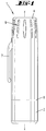
- an inhaler 1 which is realized as a convenient mit réellebares, short-rod-shaped pocket device, with a shape-determining deposed, cylindrical housing. 2
- the cylindrical, tube-like housing 2 passes on the head side of the inhaler 1 into an attached mouthpiece 3, which is flattened to the mouth and can be protected by means of a cup-shaped closure cap 4.
- the latter is realized as a screw cap, for which purpose an internal thread 5 assigned to it engages in a corresponding external thread 6 on the jacket wall of the housing 2.
- a clip 7 is formed in the neck region of the mouthpiece 3 of the cap 4 in the neck region of the mouthpiece 3 of the cap 4 mantelau.
- the end edge of the cup-shaped closure cap 4 comes stop-limiting and sealing against an annular shoulder 8, which is achieved due to the aforementioned paragraph of the cylindrical housing 2.
- the cap 4 also serves as an actuating handle 9 for applying a powdery substance 10 in reproducible subsets 10 ', to which the axial screwing of the threaded engagement 5/6 is used.
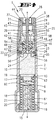
- the substance 10 is optionally refillable received in a storage chamber 11 of the housing 2.
- Each of a subset 10 'to a lying outside of the storage chamber 11 transition point U promotional metering device is denoted in its entirety by D.
- bodies susceptible to suction flow such as lactose
- bodies susceptible to suction flow can be carriers for micronized fine particles of drug adhering to the surface.
- the metering device D is connected downstream of a so-called dispersing, in which by the user a suction air flow S is generated. This carries the exactly divided subset 10 'of the substance 10 in the transfer point U rest free.
- the mouthpiece 3 conductive suction air channel is provided with the reference numeral 12.
- the lower end of the storage chamber 11 forms a cup-shaped pressure base 13, which is in the direction of the mouthpiece 3 by means of a compression spring 14 under spring load.
- the compression spring 14 is supported with the foot-side end turn on a bottom cap 15 closing the housing 2 there. This is in latching engagement with the here larger cross section section of the housing 2, wherein a corresponding locking collar 16 of the bottom cap 15 engages in a matching annular groove of the housing 2.
- the head-side end turn of the prestressed compression spring 14 acts on an inner shoulder 17 of a hollow piston 18 of the piston-shaped device 13/18.
- the stepped pot-shaped pressure base 13 is latchably connected to the inner shoulder 17 of the hollow piston 18.
- the pot edge of the pressure floor 13 provides a ring lip 19, the walls of the storage chamber 21 wears lossless due to their rubber-elastic material.
- a hollow stay pin 20 This forms, together with the hollow piston 18, which surrounds the latter at a distance, a spring chamber 21 for the compression spring 14.
- Mouthpiece side closes the pantry 11 with a cup-shaped rotary member 22, which forms the housing 2 covering the ceiling 23 of the pantry 11 with its bottom of the pot.
- a guide opening 24 is left.
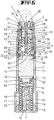
- This middle or directly executed guide opening 24 takes as the heart of the dosing device D to a plunger 25.
- the plunger slider 25 is substantially formed as a flat part with elongate rectangular cross-section. The length ratio of narrow side to broad side is in the illustrated embodiment about 1: 3.
- the plunger slide 25 forms an approximately screwdriver blade-like taper.
- the two mirror-symmetrical oblique edges start from the respective broad sides of the dip slide 25.
- the free sloping end is dull.
- the stroke of the linear and superimposed rotationally moving metering chamber 26 takes into account in both end positions of the plunger slider 25 a locking of the cross section of the guide opening 24 with meterierhunt committeeder doctor blade or Abstreichtim over the length of said opening 24th
- the mouthpiece-side end of the closure cap 4 forms a docking point 28 which latches out in the event of overload between the dip-pusher 25 and the closure cap 4.
- the closure-cap-side engagement means is a spring-capable hook collar.
- the corresponding end of the plunger slide 25 is rotationally symmetrical in cross-section, wherein a plate-shaped radial collar 29 continues to grow in the transition region from the flat part section to the cylindrical end section. With an axial distance to this radial collar 29, the end portion of the plunger slide 25 facing away from the flat part forms a latching head 30. Between this and the radial collar 29 is a wasp-waisted Ring groove 31 formed. In this engage inwardly directed lugs 32 of the resilient tongues of the hook ring.
- the latching head 30 can be overcome in both directions by the lugs 32.
- the lugs 29 and their spring tongues are realized on a tube 33 protruding into a central mouthpiece opening 3 ', which extends from the inside of the ceiling of the closure cap 4, rooted therefrom.
- the mouthpiece 3 engages over a jacket wall 34 anchoring at the neck of the housing 2.
- This anchoring is formed with respect to the representations below the rotary part ceiling 23 in the form of a latching point 35 between the two parts 2.3. This may be an irreversible detent 35.
- the ceiling 23 of the rotary member 22 is supported by an annular shoulder 36 of the jacket wall 34 supported.
- the central opening 3 'of the mouthpiece 3 is formed in the region of a cup-shaped dispersing part 37 arranged essentially in the overhead position. This by central enforcement of the Dispersiertil-bottom 38.
- the towards the rotary member 22 toward opening dispersing 37 has a pot wall 39, with an outer diameter which corresponds to the outer diameter of the pot wall 40 of the rotary member 22.
- the cup-shaped rotary member 22 and the cup-shaped dispersing 37 facing each other with their openings, the dispersing 37 is supported with its free annular edge on the associated annular edge of the rotary part pot wall 40.
- Both pot walls 39 and 40 are radially inwardly spaced from the inner wall of the casing wall 34. Accordingly, an annular space 41 respectively adjusts around the rotating part 22 and around the dispersing part 37.
- the inner diameter of the pot wall 39 of the dispersing part 37 is at the outer diameter of the plate-like radial collar 29 of the plunger slide 25th customized. Accordingly, the latter experiences a guide in the linear direction in the pot-like dispersing part 37.
- radial passages 43 are provided in the pot wall 39, for connecting the pot interior with the circumferential annulus 41. It can be provided as shown two diametrically opposite passage openings 43. Alternatively, a circumferential, interrupted by support webs passage slot may be provided.
- the dispensing annular space 44 which surrounds the bottom of the pot 38 of the dispersing part 37 is separated from the annular space 41 extending approximately in the axial extension by a sealing collar 45 projecting radially outward from the pot wall 39, which sealing collar 45 is supported on the inside of the jacket wall 34.
- the axial lengths of rotary part 22 and dispersing part 37 in the region of their cup walls 39 and 40 are selected such that the pulse-absorbing dip stroke of the plunger slide 25 is ensured from a filling level in the storage chamber 11 into the transfer point U above the ceiling 23.
- the defined emptying readiness position of the dosing chamber 26 results from the draft limit stop of the dipping slider 25 in the region of its radial collar 29 against the pot bottom 38 of the dispersing part 37.
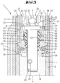
- the metering chamber 26 is realized as a transverse bore extending substantially perpendicularly to the longitudinal central axis x-x.
- This longitudinal central axis x - x also forms the axis of rotation.
- the metering chamber 26 is arranged eccentrically, so further the broad sides of the formed as a flat part plunger slide 25 passing.
- the metering chamber 26 is arranged at a distance from the free end of the plunger slider 25 associated with a side edge of the wide surface.
- the metering chamber 26 is in the range of action of the central suction air flow S.
- the metering chamber 26 is associated with an adjoining the suction air passage 12 air passage 46 which is formed in the pot wall 40 of the rotary member 22. These are radial bores extending near the bottom of the pot-shaped rotary member 22 at an axial distance above the top of the ceiling 23.
- Both open ends of the metering chamber 26 is preceded by such an air passage 46 at a radial distance.
- a provision may be that an air passage 40 of smaller diameter than the latter is assigned to the end of larger clear diameter of the metering chamber 26 formed by a conical transverse bore, and an air passage 46 of larger diameter than the end of smaller clearer diameter of the metering chamber 26.
- the cup-shaped, the plunger slide 25 leading rotary member 22 formed air passages 46 are spaced radially via a rear inflow annulus 47 still fluidly connected to air inlets 48. These are also designed as holes and connect to the atmosphere.
- the inflow annulus 47 is formed between the outside of the pot wall 40 of the cup-shaped rotary member 22 and the inside of the shell wall 34 of the mouthpiece 3, this in axial extension to the described annulus 41.
- the sealing collar 49 and 45 of the dispersing 37 prevent a flow short circuit between the air inlets 48 and the outlet annulus 44 in the region Mouthpiece 3.
- the air passages 46 are arranged axially offset from the air inlets 48, the latter being closer to the mouthpiece 3.
- the described spatial distance position leads to an initially opposing inflow of sucked air with connection to the main suction air flow S.
- the guide opening 24 for the plunger slider 25 is formed stripping, as a result of which no powder adhering to the plunger sheath, for example, is entrained in a dose-distorting manner.
- the guide opening 24 is not formed directly by the rotary member 22, but by a this passage passage lining sealing bushing 50.
- the latter consists of rubber-elastic material and is kept clipped into the ceiling 23 via latching means.
- sealing element Between the rotary member 22 and the storage chamber 11 forming housing 2 is also a sealing element. This is achieved by an inserted between the inner wall of the storage chamber 11 and the rotary member 22 sealing ring 51 made of rubber-elastic material. The latter is used under bias in annular grooves of both parts 2, 22 suitable. Both the sealing ring 51 receiving circumferential annular grooves have a semi-circular cross-sectional configuration. The corresponding regions of the sealing ring 51 are shaped accordingly.
- the sealing bush 50 is rotatably connected to the rotary member 22.
- the guide opening 24 is adapted to the cross-sectional configuration of the plunger slider 25 also elongated rectangular, according to this positive connection and the plunger slide 25 is rotatably connected to the rotary member 22.
- This bearing opening 53 is slightly enlarged with respect to the cross-sectional dimension of the flat portion portion of the plunger slider 25, according to which a low-friction displacement of the sealing plug 52 is achieved on the plunger slide 25.
- the closure piston 52 is provided with a radially outer circumferential sealing lip 54, which in a transfer standby position as shown in FIG FIG. 4 cooperates with the inner wall of the rotary part pot wall 40, this with respect to the storage chamber 11 above the air passages 46th
- the displacement of the closure piston 52 is only intentionally possible, this in the simplest way by activation of the suction air flow S, that is by conventional inhalation suction.
- the closure piston 52 is displaced along the flat portion of the plunger slide 25 axially upward, for two-sided release of the metering chamber 26.
- the closure piston 52 is in this case moved into the radially expanded Umströmungs Society 42, said axial displacement stop limit is limited.
- said axial displacement stop limit is limited.
- the radial distance of the stop webs 55 to one another corresponds to the guide cross section of the dispersing part 37 and thus to the outer diameter of the dip slide-side radial collar 29.
- closure piston 52 flows around in the region 42 of the mouthpiece 3 lying around.
- the provision of the powdery substance 10 is in the scooping area. Conditions are created which ensure a structurally identical or homogeneous filling of the dosing chamber 26, fed from a thoroughly loosened environment.
- the rotary member 22 is used. This has a rotor R acting in the upper region of the storage chamber 11. Using the rotation of the rotary member 22 results in a loosening of the stored substance.
- scoop development it Are rotor blades 56.
- two rotor blades 56 may be provided, which are arranged with respect to the longitudinal center axis x - x of the inhaler 1 in diametrical opposite position.
- the freestanding rotor blades 56 protruding from the floor or the ceiling 23 of the rotary member 22 on the supply chamber side are positioned in such a diametrical opposite position that they are sufficiently spaced in the direction of rotation. Geometrically, these can occupy substantially a quarter sector of the circular cross section of the storage chamber 11.
- the rotational drive between the mouthpiece 3 and the screw cap 4 is carried out by a claw coupling 57 between the two.
- This consists of a longitudinal toothing 58 on the jacket wall 34 of the mouthpiece 3, which longitudinal teeth 58 engage in corresponding tooth gaps 59 on the inside of the closure cap 4.
- the cap 4 follows via the jaw clutch 57, a rotational drive of the rotary member 22 and the entrained parts such as sealing bushing 50, plug 52 and plunger slide 25, wherein further by the schraubabariade displacement of the cap 4 at the same time an axial displacement of the plunger slider 25 on the Docking point 28 takes place, which is a screw-like displacement of the metering chamber 26 in the transition point U, that is in the transfer standby position shown in FIG. 4 causes.
- the closure plug 52 remains in the course of the linear displacement of the plunger slider 25 in its on the ceiling 23 of the rotary member 22 supporting, sealing position.
- the standing on the bottom cap 15 of the housing 2 Stehzapfen 20 is closed at the end by a sieve-like cover 60. In the demarcated space created thereby, a moisture absorbing material 61 is gripped.
- the plunger slide 25 can be varied with respect to the volume of its metering chamber 26.
- the heart of the metering device D namely the dip shifter 25 only needs to be replaced in order to achieve a different, exactly reproducible dosage of subsets 10 '.
- the piston-like acting pressure floor 13 is not impaired in its mobility relative to the cylinder space, which is provided by the central portion of the housing 2, since the housing there has a lying in the back of the annular lip 19 shipsaus somnsö réelle 62.
- the cup-shaped pressure base 13 has a central, the storage chamber 11 facing away from confiscation. This is inside of such depth that the rotor blade 56 in the basic position axially downwardly projecting end portion of the plunger slider 25 accommodated therein.
Landscapes
- Health & Medical Sciences (AREA)
- Engineering & Computer Science (AREA)
- Life Sciences & Earth Sciences (AREA)
- General Health & Medical Sciences (AREA)
- Veterinary Medicine (AREA)
- Biomedical Technology (AREA)
- Heart & Thoracic Surgery (AREA)
- Hematology (AREA)
- Pulmonology (AREA)
- Animal Behavior & Ethology (AREA)
- Bioinformatics & Cheminformatics (AREA)
- Public Health (AREA)
- Anesthesiology (AREA)
- Biophysics (AREA)
- Containers And Packaging Bodies Having A Special Means To Remove Contents (AREA)
- Medicinal Preparation (AREA)
- Nozzles (AREA)
- Medical Preparation Storing Or Oral Administration Devices (AREA)
- Infusion, Injection, And Reservoir Apparatuses (AREA)
- External Artificial Organs (AREA)
Priority Applications (2)
| Application Number | Priority Date | Filing Date | Title |
|---|---|---|---|
| PL05786868T PL1791584T3 (pl) | 2004-08-27 | 2005-08-19 | Inhalator do substancji sproszkowanych, zwłaszcza medycznych |
| EP07118831A EP1905473A3 (de) | 2004-08-27 | 2005-08-19 | Inhalator für pulverförmige, insbesondere medizinische Substanzen |
Applications Claiming Priority (2)
| Application Number | Priority Date | Filing Date | Title |
|---|---|---|---|
| DE102004041524A DE102004041524B4 (de) | 2004-08-27 | 2004-08-27 | Inhalator für pulverförmige, insbesondere medizinische Substanzen |
| PCT/EP2005/054094 WO2006021546A1 (de) | 2004-08-27 | 2005-08-19 | Inhalator für pulverförmige, insbesondere medizinische substanzen |
Related Child Applications (2)
| Application Number | Title | Priority Date | Filing Date |
|---|---|---|---|
| EP07118831A Division EP1905473A3 (de) | 2004-08-27 | 2005-08-19 | Inhalator für pulverförmige, insbesondere medizinische Substanzen |
| EP07118831A Division-Into EP1905473A3 (de) | 2004-08-27 | 2005-08-19 | Inhalator für pulverförmige, insbesondere medizinische Substanzen |
Publications (2)
| Publication Number | Publication Date |
|---|---|
| EP1791584A1 EP1791584A1 (de) | 2007-06-06 |
| EP1791584B1 true EP1791584B1 (de) | 2016-01-20 |
Family
ID=35229833
Family Applications (2)
| Application Number | Title | Priority Date | Filing Date |
|---|---|---|---|
| EP05786868.9A Expired - Lifetime EP1791584B1 (de) | 2004-08-27 | 2005-08-19 | Inhalator für pulverförmige, insbesondere medizinische substanzen |
| EP07118831A Withdrawn EP1905473A3 (de) | 2004-08-27 | 2005-08-19 | Inhalator für pulverförmige, insbesondere medizinische Substanzen |
Family Applications After (1)
| Application Number | Title | Priority Date | Filing Date |
|---|---|---|---|
| EP07118831A Withdrawn EP1905473A3 (de) | 2004-08-27 | 2005-08-19 | Inhalator für pulverförmige, insbesondere medizinische Substanzen |
Country Status (23)
| Country | Link |
|---|---|
| US (3) | US8327842B2 (enExample) |
| EP (2) | EP1791584B1 (enExample) |
| JP (1) | JP4608550B2 (enExample) |
| KR (2) | KR101426379B1 (enExample) |
| CN (1) | CN101048187B (enExample) |
| AU (2) | AU2005276502B2 (enExample) |
| BR (2) | BRPI0520858B8 (enExample) |
| CA (2) | CA2823392C (enExample) |
| DE (1) | DE102004041524B4 (enExample) |
| DK (1) | DK1791584T3 (enExample) |
| ES (1) | ES2568472T3 (enExample) |
| HU (1) | HUE028814T2 (enExample) |
| IL (2) | IL181189A (enExample) |
| IN (1) | IN2014DN08433A (enExample) |
| ME (2) | ME00153B (enExample) |
| MX (1) | MX2007002267A (enExample) |
| NO (1) | NO341701B1 (enExample) |
| NZ (1) | NZ553366A (enExample) |
| PL (1) | PL1791584T3 (enExample) |
| RU (1) | RU2372104C2 (enExample) |
| UA (1) | UA87861C2 (enExample) |
| WO (1) | WO2006021546A1 (enExample) |
| ZA (2) | ZA200701485B (enExample) |
Families Citing this family (26)
| Publication number | Priority date | Publication date | Assignee | Title |
|---|---|---|---|---|
| EP1539286B1 (de) | 2002-09-16 | 2015-01-21 | Sanofi SA | Inhalator für pulverförmige, insbesondere medizinische substanzen |
| EP1905472A3 (de) * | 2002-09-16 | 2008-04-16 | von Schuckmann, Alfred | Inhalator für pulverförmige, insbesondere medizinische Substanzen |
| DE102004041524B4 (de) * | 2004-08-27 | 2013-03-21 | Sanofi Sa | Inhalator für pulverförmige, insbesondere medizinische Substanzen |
| GB0625303D0 (en) * | 2006-12-19 | 2007-01-24 | Jagotec Ag | Improvements in and relating to metered dose inhalers |
| WO2009029027A1 (en) * | 2007-08-24 | 2009-03-05 | Astrazeneca Ab | Breath- triggered inhaler |
| DE102007056263A1 (de) | 2007-11-22 | 2009-05-28 | Siegfried Generics International Ag | Dosiervorrichtung zur Inhalierung einer pulverförmigen Substanz |
| WO2009079078A1 (en) | 2007-12-14 | 2009-06-25 | Labogroup S.A.S. | Delivering aerosolizable food products |
| EP2201977A1 (de) * | 2008-12-23 | 2010-06-30 | Siegfried Generics International AG | Dosiervorrichtung zur Erzeugung eines Gasstromes mit einem in diesem fein verteilten Wirkstoff |
| DE202008017185U1 (de) * | 2008-12-30 | 2010-05-12 | Siegfried Generics International Ag | Dosiervorrichtung |
| GB201118842D0 (en) | 2011-11-01 | 2011-12-14 | Euro Celtique Sa | Dispenser cap arrangement |
| AU2012344172B2 (en) * | 2011-11-30 | 2017-05-18 | Sanofi Sa | Assembly for an inhalation device, use of an organizing member, and inhalation device |
| CN104125844B (zh) * | 2011-12-12 | 2016-08-31 | 赛诺菲股份有限公司 | 用于吸入装置的组件和密封件的使用 |
| JP2015522362A (ja) * | 2012-07-20 | 2015-08-06 | サノフィ・ソシエテ・アノニム | 吸入デバイス用の計量要素および計量要素を含む吸入デバイス |
| MX354384B (es) * | 2012-11-12 | 2018-03-02 | Sanofi Sa | Ensamble para un dispositivo de inhalación y uso de un miembro de sellado. |
| KR101445651B1 (ko) * | 2013-01-15 | 2014-10-07 | 한국유나이티드제약 주식회사 | 분말 제재 흡입 장치 |
| US8920364B2 (en) | 2013-02-28 | 2014-12-30 | Medtronic Xomed, Inc. | Biomaterial delivery device |
| US8845578B2 (en) | 2013-02-28 | 2014-09-30 | Medtronic Xomed, Inc. | Biomaterial delivery device |
| DK177788B1 (en) * | 2013-07-12 | 2014-07-07 | Liita Holdings Ltd | Inhaler |
| EP3107606B1 (en) * | 2014-02-21 | 2024-08-28 | David Brown | Inhalation device for inhaling powders |
| RU2016144471A (ru) * | 2014-04-16 | 2018-05-16 | Санофи Са | Уплотнительный элемент для медицинского устройства |
| DE102015119617A1 (de) | 2015-11-13 | 2017-05-18 | Alfred Von Schuckmann | Handbetätigbarer Inhalator |
| US10953730B2 (en) * | 2016-11-02 | 2021-03-23 | Christopher A. David | Air scenting system |
| GB201812142D0 (en) * | 2018-07-25 | 2018-09-05 | 3M Innovative Properties Co | Cover device for an inhaler |
| US10828432B1 (en) * | 2019-06-24 | 2020-11-10 | De Motu Cordis Pty Ltd | Respiratory delivery device and method |
| US11793951B2 (en) | 2019-06-24 | 2023-10-24 | De Motu Cordis Pty Ltd | Automatic dispenser for respiratory delivery device and method |
| US11717621B2 (en) | 2019-06-24 | 2023-08-08 | De Motu Cordis Pty Ltd | Automatic dispenser for respiratory delivery device |
Family Cites Families (22)
| Publication number | Priority date | Publication date | Assignee | Title |
|---|---|---|---|---|
| US2029835A (en) * | 1934-09-08 | 1936-02-04 | Northam Warren Corp | Applicator |
| US4117946A (en) * | 1976-11-15 | 1978-10-03 | Milton Kessler | Plastic cap for widemouthed containers |
| US4095596A (en) * | 1976-11-26 | 1978-06-20 | Smithkline Corporation | Nasal inhaler |
| US5176132A (en) * | 1989-05-31 | 1993-01-05 | Fisons Plc | Medicament inhalation device and formulation |
| US5429122A (en) * | 1990-09-26 | 1995-07-04 | Zanen; Pieter | Inhaler devices provided with a reservoir for several doses of medium for inhaling, transporting device, whirl chamber |
| FR2676929B1 (fr) * | 1991-05-30 | 1994-02-11 | Aerosols Bouchage Ste Fse | Inhalateur de poudres. |
| US6029661A (en) * | 1991-08-26 | 2000-02-29 | 3M Innovative Properties Company | Powder dispenser |
| DE4239402A1 (de) * | 1992-11-24 | 1994-05-26 | Bayer Ag | Pulverinhalator |
| US5524613A (en) * | 1993-08-25 | 1996-06-11 | Habley Medical Technology Corporation | Controlled multi-pharmaceutical inhaler |
| DE4340768A1 (de) * | 1993-11-30 | 1995-06-01 | Bayer Ag | Vorrichtung zum Inhalieren |
| KR100629126B1 (ko) * | 1999-01-14 | 2006-09-27 | 데이진 가부시키가이샤 | 분말체의 정량 공급장치 및 방법 |
| JP2000217917A (ja) * | 1999-01-27 | 2000-08-08 | Unisia Jecs Corp | 吸入式投薬器 |
| FI990915A0 (fi) | 1999-04-23 | 1999-04-23 | Orion Yhtymae Oyj | Jauheinhalaattori |
| DE10047722A1 (de) | 2000-09-27 | 2002-04-11 | Schuckmann Alfred Von | Von Saugluftstrom des Benutzers aktivierbare Dosiervorrichtung |
| DE10106788A1 (de) * | 2001-02-12 | 2002-08-14 | Schuckmann Alfred Von | Inhalator für pulverförmige, insbesondere medizinische Substanzen |
| DE10144572B4 (de) * | 2001-09-11 | 2013-08-01 | Sanofi Sa | Inhalator für pulverförmige, insbesondere medizinische Substanzen |
| US7258118B2 (en) * | 2002-01-24 | 2007-08-21 | Sofotec Gmbh & Co, Kg | Pharmaceutical powder cartridge, and inhaler equipped with same |
| EP1539286B1 (de) | 2002-09-16 | 2015-01-21 | Sanofi SA | Inhalator für pulverförmige, insbesondere medizinische substanzen |
| DE10244795A1 (de) * | 2002-09-26 | 2004-04-08 | Boehringer Ingelheim Pharma Gmbh & Co. Kg | Pulverinhalator |
| CN2605864Y (zh) * | 2003-03-14 | 2004-03-10 | 上海华氏制药有限公司天平制药厂 | 粉雾吸入器 |
| DE102004041524B4 (de) * | 2004-08-27 | 2013-03-21 | Sanofi Sa | Inhalator für pulverförmige, insbesondere medizinische Substanzen |
| DE102007056263A1 (de) * | 2007-11-22 | 2009-05-28 | Siegfried Generics International Ag | Dosiervorrichtung zur Inhalierung einer pulverförmigen Substanz |
-
2004
- 2004-08-27 DE DE102004041524A patent/DE102004041524B4/de not_active Expired - Fee Related
-
2005
- 2005-08-19 BR BRPI0520858A patent/BRPI0520858B8/pt not_active IP Right Cessation
- 2005-08-19 EP EP05786868.9A patent/EP1791584B1/de not_active Expired - Lifetime
- 2005-08-19 KR KR1020077004540A patent/KR101426379B1/ko not_active Expired - Fee Related
- 2005-08-19 DK DK05786868.9T patent/DK1791584T3/en active
- 2005-08-19 RU RU2007111115/14A patent/RU2372104C2/ru not_active IP Right Cessation
- 2005-08-19 ME MEP-2008-18A patent/ME00153B/me unknown
- 2005-08-19 PL PL05786868T patent/PL1791584T3/pl unknown
- 2005-08-19 JP JP2007528832A patent/JP4608550B2/ja not_active Expired - Fee Related
- 2005-08-19 CN CN2005800370968A patent/CN101048187B/zh not_active Expired - Fee Related
- 2005-08-19 MX MX2007002267A patent/MX2007002267A/es active IP Right Grant
- 2005-08-19 NZ NZ553366A patent/NZ553366A/en not_active IP Right Cessation
- 2005-08-19 BR BRPI0514688-7A patent/BRPI0514688B1/pt not_active IP Right Cessation
- 2005-08-19 US US11/660,887 patent/US8327842B2/en not_active Expired - Fee Related
- 2005-08-19 AU AU2005276502A patent/AU2005276502B2/en not_active Ceased
- 2005-08-19 ZA ZA200701485A patent/ZA200701485B/xx unknown
- 2005-08-19 HU HUE05786868A patent/HUE028814T2/en unknown
- 2005-08-19 KR KR1020137026596A patent/KR101426374B1/ko not_active Expired - Fee Related
- 2005-08-19 UA UAA200702136A patent/UA87861C2/uk unknown
- 2005-08-19 EP EP07118831A patent/EP1905473A3/de not_active Withdrawn
- 2005-08-19 CA CA2823392A patent/CA2823392C/en not_active Expired - Fee Related
- 2005-08-19 ES ES05786868.9T patent/ES2568472T3/es not_active Expired - Lifetime
- 2005-08-19 ME MEP-18/08A patent/MEP1808A/xx unknown
- 2005-08-19 WO PCT/EP2005/054094 patent/WO2006021546A1/de not_active Ceased
- 2005-08-19 CA CA2576074A patent/CA2576074C/en not_active Expired - Fee Related
-
2007
- 2007-02-06 IL IL181189A patent/IL181189A/en not_active IP Right Cessation
- 2007-03-26 NO NO20071565A patent/NO341701B1/no not_active IP Right Cessation
-
2008
- 2008-04-03 US US12/062,225 patent/US8701660B2/en not_active Expired - Fee Related
- 2008-08-19 ZA ZA200807138A patent/ZA200807138B/en unknown
-
2011
- 2011-03-31 AU AU2011201465A patent/AU2011201465B2/en not_active Ceased
-
2012
- 2012-07-25 IL IL221103A patent/IL221103B/en not_active IP Right Cessation
- 2012-12-07 US US13/708,053 patent/US20130092161A1/en not_active Abandoned
-
2014
- 2014-10-09 IN IN8433DEN2014 patent/IN2014DN08433A/en unknown
Also Published As
Similar Documents
| Publication | Publication Date | Title |
|---|---|---|
| EP1791584B1 (de) | Inhalator für pulverförmige, insbesondere medizinische substanzen | |
| EP2497514B1 (de) | Inhalator für pulverförmige, insbesondere medizinische Substanzen | |
| EP1993643B1 (de) | Inhalator für pulverförmige substanzen | |
| EP2214760B1 (de) | Dosiervorrichtung zur inhalierung einer pulverförmigen substanz | |
| EP1220700B1 (de) | Atemzugskontrolliertes Inhalationsgerät für Trockenpulver | |
| EP1523365B1 (de) | Handbetätigbarer inhalator für pulverförmige substanzen | |
| EP2707067A1 (de) | Vorrichtung zum inhalieren pulverförmiger substanzen | |
| DE102005033397A1 (de) | Inhalator für pulverförmige, insbesondere medizinische Substanzen | |
| WO2019158771A1 (de) | Vorrichtung zur bevorratung und ausgabe von verbindungselementen | |
| DE102004064245B3 (de) | Inhalator für pulverförmige, insbesondere medizinische Substanzen | |
| EP1905472A2 (de) | Inhalator für pulverförmige, insbesondere medizinische Substanzen | |
| WO2017144182A1 (de) | Inhalator | |
| DE10144572B4 (de) | Inhalator für pulverförmige, insbesondere medizinische Substanzen | |
| DE10165101B3 (de) | Inhalator für pulverförmige, insbesondere medizinische Substanzen | |
| DE10165112B3 (de) | Inhalator für pulverförmige, insbesondere medizinische Substanzen | |
| EP2363354B1 (de) | Spender eines Wirkstoffs | |
| WO2008125402A1 (de) | Inhalator für pulverförmige substanzen | |
| WO2008125401A2 (de) | Inhalator für pulverförmige substanzen | |
| DE10027631B4 (de) | Atemzugskontrolliertes Inhalationsgerät für Trockenpulver und Verfahren zum gleichmäßigen Verteilen des Trockenpulvers in Luft | |
| DE102015120949A1 (de) | Inhalator für pulverförmige Substanzen sowie Zählwerk für einen Inhalator | |
| WO2001015760A1 (de) | Handbetätigbarer inhalator für pulverförmige substanzen | |
| DE102006007747A1 (de) | Dosiereinrichtung |
Legal Events
| Date | Code | Title | Description |
|---|---|---|---|
| PUAI | Public reference made under article 153(3) epc to a published international application that has entered the european phase |
Free format text: ORIGINAL CODE: 0009012 |
|
| 17P | Request for examination filed |
Effective date: 20070228 |
|
| AK | Designated contracting states |
Kind code of ref document: A1 Designated state(s): AT BE BG CH CY CZ DE DK EE ES FI FR GB GR HU IE IS IT LI LT LU LV MC NL PL PT RO SE SI SK TR |
|
| AX | Request for extension of the european patent |
Extension state: AL BA HR MK YU |
|
| RAP1 | Party data changed (applicant data changed or rights of an application transferred) |
Owner name: SIEGFRIED GENERICS INTERNATIONAL AG |
|
| RIN1 | Information on inventor provided before grant (corrected) |
Inventor name: ALFRED VON SCHUCKMANN |
|
| RAP1 | Party data changed (applicant data changed or rights of an application transferred) |
Owner name: SIEGFRIED PHARMA INTERNATIONAL AG |
|
| RAP1 | Party data changed (applicant data changed or rights of an application transferred) |
Owner name: SANOFI SA |
|
| RAP1 | Party data changed (applicant data changed or rights of an application transferred) |
Owner name: SANOFI SA |
|
| GRAP | Despatch of communication of intention to grant a patent |
Free format text: ORIGINAL CODE: EPIDOSNIGR1 |
|
| INTG | Intention to grant announced |
Effective date: 20150716 |
|
| GRAS | Grant fee paid |
Free format text: ORIGINAL CODE: EPIDOSNIGR3 |
|
| GRAA | (expected) grant |
Free format text: ORIGINAL CODE: 0009210 |
|
| RBV | Designated contracting states (corrected) |
Designated state(s): AT BE BG CH CY CZ DE DK EE ES FI FR GB GR HU IE IS IT LI LT LV NL PL PT RO SE SI SK TR |
|
| AK | Designated contracting states |
Kind code of ref document: B1 Designated state(s): AT BE BG CH CY CZ DE DK EE ES FI FR GB GR HU IE IS IT LI LT LV NL PL PT RO SE SI SK TR |
|
| AX | Request for extension of the european patent |
Extension state: AL BA HR MK YU |
|
| REG | Reference to a national code |
Ref country code: GB Ref legal event code: FG4D Free format text: NOT ENGLISH |
|
| REG | Reference to a national code |
Ref country code: CH Ref legal event code: EP |
|
| REG | Reference to a national code |
Ref country code: IE Ref legal event code: FG4D Free format text: LANGUAGE OF EP DOCUMENT: GERMAN |
|
| REG | Reference to a national code |
Ref country code: AT Ref legal event code: REF Ref document number: 771410 Country of ref document: AT Kind code of ref document: T Effective date: 20160215 |
|
| REG | Reference to a national code |
Ref country code: DE Ref legal event code: R096 Ref document number: 502005015089 Country of ref document: DE |
|
| REG | Reference to a national code |
Ref country code: DK Ref legal event code: T3 Effective date: 20160415 |
|
| REG | Reference to a national code |
Ref country code: ES Ref legal event code: FG2A Ref document number: 2568472 Country of ref document: ES Kind code of ref document: T3 Effective date: 20160429 |
|
| REG | Reference to a national code |
Ref country code: NL Ref legal event code: FP |
|
| REG | Reference to a national code |
Ref country code: SE Ref legal event code: TRGR |
|
| REG | Reference to a national code |
Ref country code: LT Ref legal event code: MG4D |
|
| REG | Reference to a national code |
Ref country code: FR Ref legal event code: PLFP Year of fee payment: 12 |
|
| PG25 | Lapsed in a contracting state [announced via postgrant information from national office to epo] |
Ref country code: GR Free format text: LAPSE BECAUSE OF FAILURE TO SUBMIT A TRANSLATION OF THE DESCRIPTION OR TO PAY THE FEE WITHIN THE PRESCRIBED TIME-LIMIT Effective date: 20160421 Ref country code: FI Free format text: LAPSE BECAUSE OF FAILURE TO SUBMIT A TRANSLATION OF THE DESCRIPTION OR TO PAY THE FEE WITHIN THE PRESCRIBED TIME-LIMIT Effective date: 20160120 |
|
| PG25 | Lapsed in a contracting state [announced via postgrant information from national office to epo] |
Ref country code: LT Free format text: LAPSE BECAUSE OF FAILURE TO SUBMIT A TRANSLATION OF THE DESCRIPTION OR TO PAY THE FEE WITHIN THE PRESCRIBED TIME-LIMIT Effective date: 20160120 Ref country code: PT Free format text: LAPSE BECAUSE OF FAILURE TO SUBMIT A TRANSLATION OF THE DESCRIPTION OR TO PAY THE FEE WITHIN THE PRESCRIBED TIME-LIMIT Effective date: 20160520 Ref country code: LV Free format text: LAPSE BECAUSE OF FAILURE TO SUBMIT A TRANSLATION OF THE DESCRIPTION OR TO PAY THE FEE WITHIN THE PRESCRIBED TIME-LIMIT Effective date: 20160120 Ref country code: IS Free format text: LAPSE BECAUSE OF FAILURE TO SUBMIT A TRANSLATION OF THE DESCRIPTION OR TO PAY THE FEE WITHIN THE PRESCRIBED TIME-LIMIT Effective date: 20160520 |
|
| REG | Reference to a national code |
Ref country code: DE Ref legal event code: R097 Ref document number: 502005015089 Country of ref document: DE |
|
| PG25 | Lapsed in a contracting state [announced via postgrant information from national office to epo] |
Ref country code: EE Free format text: LAPSE BECAUSE OF FAILURE TO SUBMIT A TRANSLATION OF THE DESCRIPTION OR TO PAY THE FEE WITHIN THE PRESCRIBED TIME-LIMIT Effective date: 20160120 |
|
| PLBE | No opposition filed within time limit |
Free format text: ORIGINAL CODE: 0009261 |
|
| STAA | Information on the status of an ep patent application or granted ep patent |
Free format text: STATUS: NO OPPOSITION FILED WITHIN TIME LIMIT |
|
| PG25 | Lapsed in a contracting state [announced via postgrant information from national office to epo] |
Ref country code: SK Free format text: LAPSE BECAUSE OF FAILURE TO SUBMIT A TRANSLATION OF THE DESCRIPTION OR TO PAY THE FEE WITHIN THE PRESCRIBED TIME-LIMIT Effective date: 20160120 Ref country code: RO Free format text: LAPSE BECAUSE OF FAILURE TO SUBMIT A TRANSLATION OF THE DESCRIPTION OR TO PAY THE FEE WITHIN THE PRESCRIBED TIME-LIMIT Effective date: 20160120 |
|
| 26N | No opposition filed |
Effective date: 20161021 |
|
| REG | Reference to a national code |
Ref country code: HU Ref legal event code: AG4A Ref document number: E028814 Country of ref document: HU |
|
| PG25 | Lapsed in a contracting state [announced via postgrant information from national office to epo] |
Ref country code: SI Free format text: LAPSE BECAUSE OF FAILURE TO SUBMIT A TRANSLATION OF THE DESCRIPTION OR TO PAY THE FEE WITHIN THE PRESCRIBED TIME-LIMIT Effective date: 20160120 Ref country code: BG Free format text: LAPSE BECAUSE OF FAILURE TO SUBMIT A TRANSLATION OF THE DESCRIPTION OR TO PAY THE FEE WITHIN THE PRESCRIBED TIME-LIMIT Effective date: 20160420 |
|
| REG | Reference to a national code |
Ref country code: FR Ref legal event code: PLFP Year of fee payment: 13 |
|
| PGFP | Annual fee paid to national office [announced via postgrant information from national office to epo] |
Ref country code: NL Payment date: 20170814 Year of fee payment: 13 |
|
| REG | Reference to a national code |
Ref country code: AT Ref legal event code: MM01 Ref document number: 771410 Country of ref document: AT Kind code of ref document: T Effective date: 20160819 |
|
| PG25 | Lapsed in a contracting state [announced via postgrant information from national office to epo] |
Ref country code: AT Free format text: LAPSE BECAUSE OF NON-PAYMENT OF DUE FEES Effective date: 20160819 |
|
| PGFP | Annual fee paid to national office [announced via postgrant information from national office to epo] |
Ref country code: ES Payment date: 20170901 Year of fee payment: 13 Ref country code: CH Payment date: 20170814 Year of fee payment: 13 Ref country code: DE Payment date: 20170815 Year of fee payment: 13 Ref country code: IT Payment date: 20170824 Year of fee payment: 13 |
|
| REG | Reference to a national code |
Ref country code: DE Ref legal event code: R082 Ref document number: 502005015089 Country of ref document: DE Representative=s name: ZSP PATENTANWAELTE PARTG MBB, DE |
|
| PGFP | Annual fee paid to national office [announced via postgrant information from national office to epo] |
Ref country code: DK Payment date: 20170810 Year of fee payment: 13 Ref country code: SE Payment date: 20170810 Year of fee payment: 13 Ref country code: IE Payment date: 20170809 Year of fee payment: 13 |
|
| PG25 | Lapsed in a contracting state [announced via postgrant information from national office to epo] |
Ref country code: CY Free format text: LAPSE BECAUSE OF FAILURE TO SUBMIT A TRANSLATION OF THE DESCRIPTION OR TO PAY THE FEE WITHIN THE PRESCRIBED TIME-LIMIT Effective date: 20160120 |
|
| REG | Reference to a national code |
Ref country code: FR Ref legal event code: PLFP Year of fee payment: 14 |
|
| PGFP | Annual fee paid to national office [announced via postgrant information from national office to epo] |
Ref country code: PL Payment date: 20180613 Year of fee payment: 14 Ref country code: BE Payment date: 20180614 Year of fee payment: 14 |
|
| PGFP | Annual fee paid to national office [announced via postgrant information from national office to epo] |
Ref country code: FR Payment date: 20180712 Year of fee payment: 14 |
|
| PGFP | Annual fee paid to national office [announced via postgrant information from national office to epo] |
Ref country code: HU Payment date: 20180802 Year of fee payment: 14 Ref country code: CZ Payment date: 20180801 Year of fee payment: 14 Ref country code: TR Payment date: 20180807 Year of fee payment: 14 |
|
| REG | Reference to a national code |
Ref country code: DE Ref legal event code: R119 Ref document number: 502005015089 Country of ref document: DE |
|
| REG | Reference to a national code |
Ref country code: DK Ref legal event code: EBP Effective date: 20180831 |
|
| REG | Reference to a national code |
Ref country code: CH Ref legal event code: PL |
|
| REG | Reference to a national code |
Ref country code: SE Ref legal event code: EUG |
|
| REG | Reference to a national code |
Ref country code: NL Ref legal event code: MM Effective date: 20180901 |
|
| GBPC | Gb: european patent ceased through non-payment of renewal fee |
Effective date: 20180819 |
|
| PG25 | Lapsed in a contracting state [announced via postgrant information from national office to epo] |
Ref country code: CH Free format text: LAPSE BECAUSE OF NON-PAYMENT OF DUE FEES Effective date: 20180831 Ref country code: LI Free format text: LAPSE BECAUSE OF NON-PAYMENT OF DUE FEES Effective date: 20180831 |
|
| REG | Reference to a national code |
Ref country code: IE Ref legal event code: MM4A |
|
| PG25 | Lapsed in a contracting state [announced via postgrant information from national office to epo] |
Ref country code: SE Free format text: LAPSE BECAUSE OF NON-PAYMENT OF DUE FEES Effective date: 20180820 |
|
| PG25 | Lapsed in a contracting state [announced via postgrant information from national office to epo] |
Ref country code: NL Free format text: LAPSE BECAUSE OF NON-PAYMENT OF DUE FEES Effective date: 20180901 |
|
| PG25 | Lapsed in a contracting state [announced via postgrant information from national office to epo] |
Ref country code: DE Free format text: LAPSE BECAUSE OF NON-PAYMENT OF DUE FEES Effective date: 20190301 Ref country code: IT Free format text: LAPSE BECAUSE OF NON-PAYMENT OF DUE FEES Effective date: 20180819 Ref country code: IE Free format text: LAPSE BECAUSE OF NON-PAYMENT OF DUE FEES Effective date: 20180819 Ref country code: DK Free format text: LAPSE BECAUSE OF NON-PAYMENT OF DUE FEES Effective date: 20180831 |
|
| REG | Reference to a national code |
Ref country code: ES Ref legal event code: FD2A Effective date: 20190918 |
|
| PG25 | Lapsed in a contracting state [announced via postgrant information from national office to epo] |
Ref country code: GB Free format text: LAPSE BECAUSE OF NON-PAYMENT OF DUE FEES Effective date: 20180819 Ref country code: ES Free format text: LAPSE BECAUSE OF NON-PAYMENT OF DUE FEES Effective date: 20180820 |
|
| PG25 | Lapsed in a contracting state [announced via postgrant information from national office to epo] |
Ref country code: HU Free format text: LAPSE BECAUSE OF NON-PAYMENT OF DUE FEES Effective date: 20190820 |
|
| PG25 | Lapsed in a contracting state [announced via postgrant information from national office to epo] |
Ref country code: CZ Free format text: LAPSE BECAUSE OF NON-PAYMENT OF DUE FEES Effective date: 20190819 |
|
| REG | Reference to a national code |
Ref country code: BE Ref legal event code: MM Effective date: 20190831 |
|
| PG25 | Lapsed in a contracting state [announced via postgrant information from national office to epo] |
Ref country code: FR Free format text: LAPSE BECAUSE OF NON-PAYMENT OF DUE FEES Effective date: 20190831 |
|
| PG25 | Lapsed in a contracting state [announced via postgrant information from national office to epo] |
Ref country code: BE Free format text: LAPSE BECAUSE OF NON-PAYMENT OF DUE FEES Effective date: 20190831 |
|
| PG25 | Lapsed in a contracting state [announced via postgrant information from national office to epo] |
Ref country code: PL Free format text: LAPSE BECAUSE OF NON-PAYMENT OF DUE FEES Effective date: 20190819 |
|
| PG25 | Lapsed in a contracting state [announced via postgrant information from national office to epo] |
Ref country code: TR Free format text: LAPSE BECAUSE OF NON-PAYMENT OF DUE FEES Effective date: 20190819 |