EP1791584B1 - Inhalator für pulverförmige, insbesondere medizinische substanzen - Google Patents
Inhalator für pulverförmige, insbesondere medizinische substanzen Download PDFInfo
- Publication number
- EP1791584B1 EP1791584B1 EP05786868.9A EP05786868A EP1791584B1 EP 1791584 B1 EP1791584 B1 EP 1791584B1 EP 05786868 A EP05786868 A EP 05786868A EP 1791584 B1 EP1791584 B1 EP 1791584B1
- Authority
- EP
- European Patent Office
- Prior art keywords
- plunger
- substance
- chamber
- inhaler
- suction air
- Prior art date
- Legal status (The legal status is an assumption and is not a legal conclusion. Google has not performed a legal analysis and makes no representation as to the accuracy of the status listed.)
- Active
Links
Images


Classifications
-
- A—HUMAN NECESSITIES
- A61—MEDICAL OR VETERINARY SCIENCE; HYGIENE
- A61M—DEVICES FOR INTRODUCING MEDIA INTO, OR ONTO, THE BODY; DEVICES FOR TRANSDUCING BODY MEDIA OR FOR TAKING MEDIA FROM THE BODY; DEVICES FOR PRODUCING OR ENDING SLEEP OR STUPOR
- A61M15/00—Inhalators
-
- A—HUMAN NECESSITIES
- A61—MEDICAL OR VETERINARY SCIENCE; HYGIENE
- A61M—DEVICES FOR INTRODUCING MEDIA INTO, OR ONTO, THE BODY; DEVICES FOR TRANSDUCING BODY MEDIA OR FOR TAKING MEDIA FROM THE BODY; DEVICES FOR PRODUCING OR ENDING SLEEP OR STUPOR
- A61M15/00—Inhalators
- A61M15/0001—Details of inhalators; Constructional features thereof
- A61M15/0005—Details of inhalators; Constructional features thereof with means for agitating the medicament
- A61M15/0006—Details of inhalators; Constructional features thereof with means for agitating the medicament using rotating means
-
- A—HUMAN NECESSITIES
- A61—MEDICAL OR VETERINARY SCIENCE; HYGIENE
- A61M—DEVICES FOR INTRODUCING MEDIA INTO, OR ONTO, THE BODY; DEVICES FOR TRANSDUCING BODY MEDIA OR FOR TAKING MEDIA FROM THE BODY; DEVICES FOR PRODUCING OR ENDING SLEEP OR STUPOR
- A61M15/00—Inhalators
- A61M15/0001—Details of inhalators; Constructional features thereof
- A61M15/0005—Details of inhalators; Constructional features thereof with means for agitating the medicament
-
- A—HUMAN NECESSITIES
- A61—MEDICAL OR VETERINARY SCIENCE; HYGIENE
- A61M—DEVICES FOR INTRODUCING MEDIA INTO, OR ONTO, THE BODY; DEVICES FOR TRANSDUCING BODY MEDIA OR FOR TAKING MEDIA FROM THE BODY; DEVICES FOR PRODUCING OR ENDING SLEEP OR STUPOR
- A61M15/00—Inhalators
- A61M15/0001—Details of inhalators; Constructional features thereof
- A61M15/002—Details of inhalators; Constructional features thereof with air flow regulating means
-
- A—HUMAN NECESSITIES
- A61—MEDICAL OR VETERINARY SCIENCE; HYGIENE
- A61M—DEVICES FOR INTRODUCING MEDIA INTO, OR ONTO, THE BODY; DEVICES FOR TRANSDUCING BODY MEDIA OR FOR TAKING MEDIA FROM THE BODY; DEVICES FOR PRODUCING OR ENDING SLEEP OR STUPOR
- A61M15/00—Inhalators
- A61M15/0001—Details of inhalators; Constructional features thereof
- A61M15/0021—Mouthpieces therefor
- A61M15/0025—Mouthpieces therefor with caps
-
- A—HUMAN NECESSITIES
- A61—MEDICAL OR VETERINARY SCIENCE; HYGIENE
- A61M—DEVICES FOR INTRODUCING MEDIA INTO, OR ONTO, THE BODY; DEVICES FOR TRANSDUCING BODY MEDIA OR FOR TAKING MEDIA FROM THE BODY; DEVICES FOR PRODUCING OR ENDING SLEEP OR STUPOR
- A61M15/00—Inhalators
- A61M15/0065—Inhalators with dosage or measuring devices
-
- A—HUMAN NECESSITIES
- A61—MEDICAL OR VETERINARY SCIENCE; HYGIENE
- A61M—DEVICES FOR INTRODUCING MEDIA INTO, OR ONTO, THE BODY; DEVICES FOR TRANSDUCING BODY MEDIA OR FOR TAKING MEDIA FROM THE BODY; DEVICES FOR PRODUCING OR ENDING SLEEP OR STUPOR
- A61M15/00—Inhalators
- A61M15/0086—Inhalation chambers
-
- A—HUMAN NECESSITIES
- A61—MEDICAL OR VETERINARY SCIENCE; HYGIENE
- A61M—DEVICES FOR INTRODUCING MEDIA INTO, OR ONTO, THE BODY; DEVICES FOR TRANSDUCING BODY MEDIA OR FOR TAKING MEDIA FROM THE BODY; DEVICES FOR PRODUCING OR ENDING SLEEP OR STUPOR
- A61M15/00—Inhalators
- A61M15/0091—Inhalators mechanically breath-triggered
-
- A—HUMAN NECESSITIES
- A61—MEDICAL OR VETERINARY SCIENCE; HYGIENE
- A61M—DEVICES FOR INTRODUCING MEDIA INTO, OR ONTO, THE BODY; DEVICES FOR TRANSDUCING BODY MEDIA OR FOR TAKING MEDIA FROM THE BODY; DEVICES FOR PRODUCING OR ENDING SLEEP OR STUPOR
- A61M2202/00—Special media to be introduced, removed or treated
- A61M2202/06—Solids
- A61M2202/062—Desiccants
-
- A—HUMAN NECESSITIES
- A61—MEDICAL OR VETERINARY SCIENCE; HYGIENE
- A61M—DEVICES FOR INTRODUCING MEDIA INTO, OR ONTO, THE BODY; DEVICES FOR TRANSDUCING BODY MEDIA OR FOR TAKING MEDIA FROM THE BODY; DEVICES FOR PRODUCING OR ENDING SLEEP OR STUPOR
- A61M2202/00—Special media to be introduced, removed or treated
- A61M2202/06—Solids
- A61M2202/064—Powder
Definitions
- the invention relates to an inhaler for powdered, in particular medicinal substances, with a leading to a mouthpiece Saugluftkanal, also a storage chamber for the substance and a linear and superimposed rotationally moving metering chamber for dividing a certain amount of substance from the storage chamber and transfer of the substance in a transfer position, for transfer to the suction air flow.
- An inhaler of the type in question is from the DE 10 144 572 A1 known.
- the object of the invention is to further develop a generic inhaler, in particular with regard to the loading of the metering chamber by separating a certain amount of substance from the storage chamber in an advantageous manner.
- an inhaler 1 which is realized as a convenient mit réellebares, short-rod-shaped pocket device, with a shape-determining deposed, cylindrical housing. 2
- the cylindrical, tube-like housing 2 passes on the head side of the inhaler 1 into an attached mouthpiece 3, which is flattened to the mouth and can be protected by means of a cup-shaped closure cap 4.
- the latter is realized as a screw cap, for which purpose an internal thread 5 assigned to it engages in a corresponding external thread 6 on the jacket wall of the housing 2.
- a clip 7 is formed in the neck region of the mouthpiece 3 of the cap 4 in the neck region of the mouthpiece 3 of the cap 4 mantelau.
- the end edge of the cup-shaped closure cap 4 comes stop-limiting and sealing against an annular shoulder 8, which is achieved due to the aforementioned paragraph of the cylindrical housing 2.
- the cap 4 also serves as an actuating handle 9 for applying a powdery substance 10 in reproducible subsets 10 ', to which the axial screwing of the threaded engagement 5/6 is used.
- the substance 10 is optionally refillable received in a storage chamber 11 of the housing 2.
- Each of a subset 10 'to a lying outside of the storage chamber 11 transition point U promotional metering device is denoted in its entirety by D.
- bodies susceptible to suction flow such as lactose
- bodies susceptible to suction flow can be carriers for micronized fine particles of drug adhering to the surface.
- the metering device D is connected downstream of a so-called dispersing, in which by the user a suction air flow S is generated. This carries the exactly divided subset 10 'of the substance 10 in the transfer point U rest free.
- the mouthpiece 3 conductive suction air channel is provided with the reference numeral 12.
- the lower end of the storage chamber 11 forms a cup-shaped pressure base 13, which is in the direction of the mouthpiece 3 by means of a compression spring 14 under spring load.
- the compression spring 14 is supported with the foot-side end turn on a bottom cap 15 closing the housing 2 there. This is in latching engagement with the here larger cross section section of the housing 2, wherein a corresponding locking collar 16 of the bottom cap 15 engages in a matching annular groove of the housing 2.
- the head-side end turn of the prestressed compression spring 14 acts on an inner shoulder 17 of a hollow piston 18 of the piston-shaped device 13/18.
- the stepped pot-shaped pressure base 13 is latchably connected to the inner shoulder 17 of the hollow piston 18.
- the pot edge of the pressure floor 13 provides a ring lip 19, the walls of the storage chamber 21 wears lossless due to their rubber-elastic material.
- a hollow stay pin 20 This forms, together with the hollow piston 18, which surrounds the latter at a distance, a spring chamber 21 for the compression spring 14.
- Mouthpiece side closes the pantry 11 with a cup-shaped rotary member 22, which forms the housing 2 covering the ceiling 23 of the pantry 11 with its bottom of the pot.
- a guide opening 24 is left.
- This middle or directly executed guide opening 24 takes as the heart of the dosing device D to a plunger 25.
- the plunger slider 25 is substantially formed as a flat part with elongate rectangular cross-section. The length ratio of narrow side to broad side is in the illustrated embodiment about 1: 3.
- the plunger slide 25 forms an approximately screwdriver blade-like taper.
- the two mirror-symmetrical oblique edges start from the respective broad sides of the dip slide 25.
- the free sloping end is dull.
- the stroke of the linear and superimposed rotationally moving metering chamber 26 takes into account in both end positions of the plunger slider 25 a locking of the cross section of the guide opening 24 with meterierhunt committeeder doctor blade or Abstreichtim over the length of said opening 24th
- the mouthpiece-side end of the closure cap 4 forms a docking point 28 which latches out in the event of overload between the dip-pusher 25 and the closure cap 4.
- the closure-cap-side engagement means is a spring-capable hook collar.
- the corresponding end of the plunger slide 25 is rotationally symmetrical in cross-section, wherein a plate-shaped radial collar 29 continues to grow in the transition region from the flat part section to the cylindrical end section. With an axial distance to this radial collar 29, the end portion of the plunger slide 25 facing away from the flat part forms a latching head 30. Between this and the radial collar 29 is a wasp-waisted Ring groove 31 formed. In this engage inwardly directed lugs 32 of the resilient tongues of the hook ring.
- the latching head 30 can be overcome in both directions by the lugs 32.
- the lugs 29 and their spring tongues are realized on a tube 33 protruding into a central mouthpiece opening 3 ', which extends from the inside of the ceiling of the closure cap 4, rooted therefrom.
- the mouthpiece 3 engages over a jacket wall 34 anchoring at the neck of the housing 2.
- This anchoring is formed with respect to the representations below the rotary part ceiling 23 in the form of a latching point 35 between the two parts 2.3. This may be an irreversible detent 35.
- the ceiling 23 of the rotary member 22 is supported by an annular shoulder 36 of the jacket wall 34 supported.
- the central opening 3 'of the mouthpiece 3 is formed in the region of a cup-shaped dispersing part 37 arranged essentially in the overhead position. This by central enforcement of the Dispersiertil-bottom 38.
- the towards the rotary member 22 toward opening dispersing 37 has a pot wall 39, with an outer diameter which corresponds to the outer diameter of the pot wall 40 of the rotary member 22.
- the cup-shaped rotary member 22 and the cup-shaped dispersing 37 facing each other with their openings, the dispersing 37 is supported with its free annular edge on the associated annular edge of the rotary part pot wall 40.
- Both pot walls 39 and 40 are radially inwardly spaced from the inner wall of the casing wall 34. Accordingly, an annular space 41 respectively adjusts around the rotating part 22 and around the dispersing part 37.
- the inner diameter of the pot wall 39 of the dispersing part 37 is at the outer diameter of the plate-like radial collar 29 of the plunger slide 25th customized. Accordingly, the latter experiences a guide in the linear direction in the pot-like dispersing part 37.
- radial passages 43 are provided in the pot wall 39, for connecting the pot interior with the circumferential annulus 41. It can be provided as shown two diametrically opposite passage openings 43. Alternatively, a circumferential, interrupted by support webs passage slot may be provided.
- the dispensing annular space 44 which surrounds the bottom of the pot 38 of the dispersing part 37 is separated from the annular space 41 extending approximately in the axial extension by a sealing collar 45 projecting radially outward from the pot wall 39, which sealing collar 45 is supported on the inside of the jacket wall 34.
- the axial lengths of rotary part 22 and dispersing part 37 in the region of their cup walls 39 and 40 are selected such that the pulse-absorbing dip stroke of the plunger slide 25 is ensured from a filling level in the storage chamber 11 into the transfer point U above the ceiling 23.
- the defined emptying readiness position of the dosing chamber 26 results from the draft limit stop of the dipping slider 25 in the region of its radial collar 29 against the pot bottom 38 of the dispersing part 37.
- the metering chamber 26 is realized as a transverse bore extending substantially perpendicularly to the longitudinal central axis x-x.
- This longitudinal central axis x - x also forms the axis of rotation.
- the metering chamber 26 is arranged eccentrically, so further the broad sides of the formed as a flat part plunger slide 25 passing.
- the metering chamber 26 is arranged at a distance from the free end of the plunger slider 25 associated with a side edge of the wide surface.
- the metering chamber 26 is in the range of action of the central suction air flow S.
- the metering chamber 26 is associated with an adjoining the suction air passage 12 air passage 46 which is formed in the pot wall 40 of the rotary member 22. These are radial bores extending near the bottom of the pot-shaped rotary member 22 at an axial distance above the top of the ceiling 23.
- Both open ends of the metering chamber 26 is preceded by such an air passage 46 at a radial distance.
- a provision may be that an air passage 40 of smaller diameter than the latter is assigned to the end of larger clear diameter of the metering chamber 26 formed by a conical transverse bore, and an air passage 46 of larger diameter than the end of smaller clearer diameter of the metering chamber 26.
- the cup-shaped, the plunger slide 25 leading rotary member 22 formed air passages 46 are spaced radially via a rear inflow annulus 47 still fluidly connected to air inlets 48. These are also designed as holes and connect to the atmosphere.
- the inflow annulus 47 is formed between the outside of the pot wall 40 of the cup-shaped rotary member 22 and the inside of the shell wall 34 of the mouthpiece 3, this in axial extension to the described annulus 41.
- the sealing collar 49 and 45 of the dispersing 37 prevent a flow short circuit between the air inlets 48 and the outlet annulus 44 in the region Mouthpiece 3.
- the air passages 46 are arranged axially offset from the air inlets 48, the latter being closer to the mouthpiece 3.
- the described spatial distance position leads to an initially opposing inflow of sucked air with connection to the main suction air flow S.
- the guide opening 24 for the plunger slider 25 is formed stripping, as a result of which no powder adhering to the plunger sheath, for example, is entrained in a dose-distorting manner.
- the guide opening 24 is not formed directly by the rotary member 22, but by a this passage passage lining sealing bushing 50.
- the latter consists of rubber-elastic material and is kept clipped into the ceiling 23 via latching means.
- sealing element Between the rotary member 22 and the storage chamber 11 forming housing 2 is also a sealing element. This is achieved by an inserted between the inner wall of the storage chamber 11 and the rotary member 22 sealing ring 51 made of rubber-elastic material. The latter is used under bias in annular grooves of both parts 2, 22 suitable. Both the sealing ring 51 receiving circumferential annular grooves have a semi-circular cross-sectional configuration. The corresponding regions of the sealing ring 51 are shaped accordingly.
- the sealing bush 50 is rotatably connected to the rotary member 22.
- the guide opening 24 is adapted to the cross-sectional configuration of the plunger slider 25 also elongated rectangular, according to this positive connection and the plunger slide 25 is rotatably connected to the rotary member 22.
- This bearing opening 53 is slightly enlarged with respect to the cross-sectional dimension of the flat portion portion of the plunger slider 25, according to which a low-friction displacement of the sealing plug 52 is achieved on the plunger slide 25.
- the closure piston 52 is provided with a radially outer circumferential sealing lip 54, which in a transfer standby position as shown in FIG FIG. 4 cooperates with the inner wall of the rotary part pot wall 40, this with respect to the storage chamber 11 above the air passages 46th
- the displacement of the closure piston 52 is only intentionally possible, this in the simplest way by activation of the suction air flow S, that is by conventional inhalation suction.
- the closure piston 52 is displaced along the flat portion of the plunger slide 25 axially upward, for two-sided release of the metering chamber 26.
- the closure piston 52 is in this case moved into the radially expanded Umströmungs Society 42, said axial displacement stop limit is limited.
- said axial displacement stop limit is limited.
- the radial distance of the stop webs 55 to one another corresponds to the guide cross section of the dispersing part 37 and thus to the outer diameter of the dip slide-side radial collar 29.
- closure piston 52 flows around in the region 42 of the mouthpiece 3 lying around.
- the provision of the powdery substance 10 is in the scooping area. Conditions are created which ensure a structurally identical or homogeneous filling of the dosing chamber 26, fed from a thoroughly loosened environment.
- the rotary member 22 is used. This has a rotor R acting in the upper region of the storage chamber 11. Using the rotation of the rotary member 22 results in a loosening of the stored substance.
- scoop development it Are rotor blades 56.
- two rotor blades 56 may be provided, which are arranged with respect to the longitudinal center axis x - x of the inhaler 1 in diametrical opposite position.
- the freestanding rotor blades 56 protruding from the floor or the ceiling 23 of the rotary member 22 on the supply chamber side are positioned in such a diametrical opposite position that they are sufficiently spaced in the direction of rotation. Geometrically, these can occupy substantially a quarter sector of the circular cross section of the storage chamber 11.
- the rotational drive between the mouthpiece 3 and the screw cap 4 is carried out by a claw coupling 57 between the two.
- This consists of a longitudinal toothing 58 on the jacket wall 34 of the mouthpiece 3, which longitudinal teeth 58 engage in corresponding tooth gaps 59 on the inside of the closure cap 4.
- the cap 4 follows via the jaw clutch 57, a rotational drive of the rotary member 22 and the entrained parts such as sealing bushing 50, plug 52 and plunger slide 25, wherein further by the schraubabariade displacement of the cap 4 at the same time an axial displacement of the plunger slider 25 on the Docking point 28 takes place, which is a screw-like displacement of the metering chamber 26 in the transition point U, that is in the transfer standby position shown in FIG. 4 causes.
- the closure plug 52 remains in the course of the linear displacement of the plunger slider 25 in its on the ceiling 23 of the rotary member 22 supporting, sealing position.
- the standing on the bottom cap 15 of the housing 2 Stehzapfen 20 is closed at the end by a sieve-like cover 60. In the demarcated space created thereby, a moisture absorbing material 61 is gripped.
- the plunger slide 25 can be varied with respect to the volume of its metering chamber 26.
- the heart of the metering device D namely the dip shifter 25 only needs to be replaced in order to achieve a different, exactly reproducible dosage of subsets 10 '.
- the piston-like acting pressure floor 13 is not impaired in its mobility relative to the cylinder space, which is provided by the central portion of the housing 2, since the housing there has a lying in the back of the annular lip 19 shipsaus somnsö réelle 62.
- the cup-shaped pressure base 13 has a central, the storage chamber 11 facing away from confiscation. This is inside of such depth that the rotor blade 56 in the basic position axially downwardly projecting end portion of the plunger slider 25 accommodated therein.
Description
- Die Erfindung betrifft einen Inhalator für pulverförmige, insbesondere medizinische Substanzen, mit einem zu einem Mundstück führenden Saugluftkanal, ferner einer Vorratskammer für die Substanz und einer linear sowie überlagert rotatorisch bewegten Dosierkammer zum Abteilen einer bestimmten Substanzmenge aus der Vorratskammer und Verbringen der Substanzmenge in eine Übergabeposition, zur Übergabe an den Saugluftstrom.
- Ein Inhalator der in Rede stehenden Art ist aus der
DE 10 144 572 A1 bekannt. - Aufgabe der Erfindung ist es, einen gattungsgemäßen Inhalator, insbesondere im Hinblick auf die Beladung der Dosierkammer durch Abteilen einer bestimmten Substanzmenge aus der Vorratskammer in vorteilhafter Weise weiterzubilden.
- Diese Aufgabe ist durch den Gegenstand des Anspruchs 1 gelöst, wobei darauf abgestellt ist, dass die Dosierkammer in einem als Flachteil ausgeformten Tauchschieber ausgebildet ist und exzentrisch zu der Rotationsachse ihrer überlagerten rotatorischen Bewegung angeordnet ist. Zufolge solcher Ausgestaltung ist ein baulich einfacher, funktionssicherer Inhalator erzielt, dessen Dosierkammer durch die der Linearbewegung überlagerten rotatorischen Bewegung in einfacher und sicherer Weise befüllt wird, was noch dadurch weiter unterstützt ist, dass die Dosierkammer im Zuge der Rotationsbewegung mit radialem Abstand um die Rotationsachse durch die in der Vorratskammer bevorratete Substanz zur Abschöpfung einer vorbestimmten Substanzmenge bewegt wird. Es erfolgt entsprechend ein Abschöpfen einer stets gleich großen, vordefinierten Substanzmenge aus der Vorratskammer. Diese steht nach schraubengangförmiger Verlagerung der Dosierkammer in die Übergabeposition zur Übergabe an den Saugluftstrom und damit einhergehender Inhalation bereit.
- Die Gegenstände der weiteren Ansprüche sind nachstehend im Bezug zu dem Gegenstand des Anspruchs 1 erläutert. Es wird weiter vorgeschlagen, dass die Dosierkammer bevorzugt als Querbohrung in dem als Flachteil ausgeformten Tauchschieber gestaltet ist. Als besonders vorteilhaft erweist sich hierbei, wenn, wie weiter bevorzugt, der Tauchschieber Verschlusskappen-abhängig verlagerbar ist, so dass in Ausübung der gewohnten Handhabung zum Schließen und Öffnen durch Verschlusskappendrehung zugleich eine Beladung der Dosierkammer und eine lineare, sowie überlagerte rotatorische Bewegung der Dosierkammer in die Übergabeposition erreicht wird. Eine besonders wirksame Maßnahme ergibt sich durch eine konische Querbohrung zur Ausformung der Dosierkammer. Das den Tauchschieber ausformende Flachteil weist im Querschnitt ein Kantenverhältnis von etwa 1:2 bis 1:5 auf. Das in Eintauchrichtung freie Ende dieses Flachteiles kann beispielsweise schraubendreherklingenartig ausgespitzt sein. Durch die flachteilartige Ausformung des Tauchschiebers ist ein Dreh-Auflockerungseffekt im Zentrumsbereich der in der in der Vorratskammer bevorrateten Substanz erreicht, was zugleich das Eintauchen des Tauchschiebers in den Pulversee begünstigt. Um einem Ausfallen der abgeschöpften Substanzmenge aus der Dosierkammer in der Übergabeposition vor einer Übergabe an den Saugluftstrom zu begegnen, ist in einer Weiterbildung des Erfindungsgegenstandes vorgesehen, dass der Tauchschieber außerhalb der Vorratskammer mit einem relativ zu dem Tauchschieber beweglichen Verschlusskolben zusammenwirkt. Bevorzugt ist dieser Verschlusskolben zu dem Tauchschieber relativ linear beweglich und entsprechend von dem als Flachteil ausgeformten Tauchschieber durchsetzt, was weiter die zueinander drehfeste Anordnung von Verschlusskolben und Tauchschieber bedingt. Zur Übergabe an der Substanzmenge an den Saugluftstrom ist der Verschlusskolben entsprechend zunächst in eine die Dosierkammer zur Substanzausgabe freigebende Stellung zu verlagern. Dies erfolgt bevorzugt dadurch, dass der Verschlusskolben abhängig von einem Saugunterdruck in eine Freigabestellung bezüglich der Dosierkammer zu bewegen ist. Der nötige Saugunterdruck wird im Zuge der Inhalation aufgebracht. Hierzu umfasst der Patient in für ihn bekannter Weise mit den Lippen das Mundstück des Inhalators um durch Einatmen einen Saugluftstrom in dem Saugluftkanal zu erzielen. Der hierbei automatisch aufgebaute Saugunterdruck reicht zur Verlagerung des Verschlusskolbens in die Freigabestellung und zum anschließenden Ausräumen der Dosierkammer und damit einhergehender Übergabe der Substanzmenge an den Saugluftstrom aus. Durch die Anordnung des Verschlusskolbens ist die Bevorratung der abgeschöpften Teilmenge in der Dosierkammer bis zur Inhalation, d.h. bis zur Übergabe an den Saugluftstrom gesichert. Die Freigabe bzw. das Öffnen der Dosierkammer erfolgt automatisch im Zuge der üblichen Handhabung. Um die Verteilung der pulverförmigen Substanz bzw. der abgeteilten Substanzmenge in der Saugluft weiter zu verbessern, ist der dem Übergabebereich in Strömungsrichtung nachgeschaltete, sogenannte Dispergiebereich dahingehend in vorteilhafter Weise weiter gebildet, dass der Saugluftkanal oberhalb der Dosierkammer eine Umlenkung nach radial außen aufweist. Demzufolge erfolgt vor Austritt der an den Saugluftstrom übergebenen Substanzmenge noch eine Umlenkung, wobei weiter diese nach radial außen weisende Umlenkung in einen ringraumartigen Austrittabschnitt im Bereich des Mundstückes führt. Entsprechend erfolgt der Substanzaustritt mit Bezug auf eine Draufsicht auf die Mundstückdecke kreisringförmig. Auch wird vorgeschlagen, dass der Tauchschieber selbst einen Teil der Strömungsumlenkung ausbildet, so insbesondere, in einem dem die Dosierkammer aufweisenden Flachteil abgewandten und entsprechend dem Mundstück zugewandten Endbereich in Form eines im Grundriss kreisrunden Tellers, welcher in der Übergabeposition die Umlenkung des Saugluftkanals nach radial außen bietet. Nachstehend ist die Erfindung der beigefügten Zeichnungen, welche lediglich ein Ausführungsbeispiel darstellt, näher erläutert. Es zeigt:
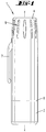
- Fig. 1
- den erfindungsgemäßen Inhalator in Seitenansicht, vergrößert, in kappenverschlossener Grundstellung;
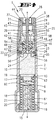
- Fig. 2
- den Vertikalschnitt hierzu;
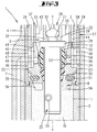
- Fig. 3
- eine Herausvergrößerung aus
Fig. 2 , den Bereich einer Dosiervorrichtung betreffend; - Fig. 4
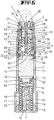
- eine Schnittdarstellung gemäß
Fig. 2 , jedoch bei abgenommener Verschlusskappe und hierdurch bedingter Verlagerung der Dosierkammer in die Endnahme-Bereitschaftstellung; - Fig. 5
- eine der
Fig. 4 entsprechende Schnittdarstellung, jedoch eine Stellung im Zuge der Inhalation darstellend; - Fig. 6
- den die Dosierkammer aufweisenden Tauchschieber in einer Einzeldarstellung in Ansicht;
- Fig. 7
- die Seitenansicht hierzu;
- Fig. 8
- in einer perspektivischen Darstellung den Tauchschieber mit einem zuordbaren Verschlusskolben sowie einer Dichtbuchse.
- Dargestellt und beschrieben ist ein Inhalator 1, welcher als bequem mitführbares, kurzstabförmiges Taschengerät realisiert ist, mit einem formbestimmenden abgesetzt, zylindrischen Gehäuse 2.
- Das zylindrische, röhrchenartige Gehäuse 2 geht kopfseitig des Inhalators 1 in ein aufgesetztes Mundstück 3 über, welches mundgerecht abgeflacht ist und sich mittels einer becherförmigen Verschlusskappe 4 schützend überfangen lässt. Letztere ist als Schraubkappe realisiert, wozu ein ihr zugeordnetes Innengewinde 5 in ein korrespondierendes Außengewinde 6 an der Mantelwand des Gehäuses 2 eingreift. Im Ansatzbereich des Mundstückes 3 ist der Verschlusskappe 4 mantelaußenwandig ein Clip 7 angeformt.
- Fußseitig tritt der Stirnrand der becherförmigen Verschlusskappe 4 anschlagbegrenzend und abdichtend gegen eine Ringschulter 8, welche aufgrund des vorgenannten Absatzes des zylindrischen Gehäuses 2 erzielt ist.
- Die Verschlusskappe 4 dient zugleich als Betätigungshandhabe 9 zur Ausbringung einer pulverförmigen Substanz 10 in reproduzierbaren Teilmengen 10', wozu der axiale Schraubhub des Gewindeeingriffs 5/6 genutzt wird. Die Substanz 10 ist in einer Vorratskammer 11 des Gehäuses 2 gegebenenfalls nachfüllbar aufgenommen. Die jeweils eine Teilmenge 10' an eine außerhalb der Vorratskammer 11 liegende Übergangsstelle U fördernde Dosiervorrichtung ist in ihrer Ganzheit mit D bezeichnet.
- Bezüglich des dosierfähigen Gutes handelt es sich um eine medizinische pulverförmige Substanz 10. So können beispielsweise saugstromtransportfähige Grundkörper wie Laktose Träger für oberflächenseitig anhaftende, mikronisierte Arzneimittel-Feinpartikel sein.
- Der Dosiervorrichtung D ist nachgeschaltet ein sogenannter Dispergierbereich, in welchem durch den Benutzer ein Saugluftstrom S erzeugt wird. Dieser trägt die exakt abgeteilte Teilmenge 10' der Substanz 10 in der Übergabestelle U restfrei ab. Der zum Mundstück 3 leitende Saugluftkanal ist mit dem Bezugszeichen 12 versehen.
- Den unteren Abschluss der Vorratskammer 11 bildet ein topfförmiger Druckboden 13, welcher in Richtung des Mundstückes 3 mittels einer Druckfeder 14 unter Federbelastung steht. Die Druckfeder 14 stützt sich mit der fußseitigen Endwindung an einer das Gehäuse 2 dort schließenden Bodenkappe 15 ab. Diese steht in Rasteingriff zum hier querschnittsgrößeren Abschnitt des Gehäuses 2, wobei ein entsprechender Rastkragen 16 der Bodenkappe 15 in eine passende Ringnut des Gehäuses 2 eingreift.
- Die kopfseitige Endwindung der vorgespannten Druckfeder 14 wirkt belastend auf eine Innenschulter 17 eines Hohlkolbens 18 der kolbenförmigen Einrichtung 13/18. Wie aus den Darstellungen zu erkennen, ist der gestuft topfförmige Druckboden 13 mit der Innenschulter 17 des Hohlkolbens 18 rastverbunden.
- Der Topfrand des Druckbodens 13 stellt eine Ringlippe 19, die aufgrund ihres gummielastischen Materials die Wandung der Vorratskammer 21 verlustfrei abstreift.
- Von der Bodenkappe 15 geht zentral ein Hohl-Stehzapfen 20 aus. Dieser bildet zusammen mit dem diesen mit Abstand umgebenden Hohlkolben 18 eine Federkammer 21 für die Druckfeder 14.
- Mundstückseitig schließt die Vorratskammer 11 mit einem topfförmigen Drehteil 22 ab, welches mit seinem Topfboden die das Gehäuse 2 überfangende Decke 23 der Vorratskammer 11 bildet.
- Im Zentrum der Decke 23 ist eine Führungsöffnung 24 belassen. Diese mitteloder unmittelbar ausgeführte Führungsöffnung 24 nimmt als Herzstück der Dosiervorrichtung D einen Tauchschieber 25 auf. Dieser fungiert zufolge entsprechender Ausgestaltung als eine bewegte Dosierkammer 26 für die auszuhebende Teilmenge 10', wobei die Bewegung des Tauchschiebers 25 linear in der Längsmittelachse x-x des im Wesentlichen rotationssymmetrisch gestalteten Inhalators 1 erfolgt, überlagert von einer um diese Längsmittelachse x-x durchgeführten Rotationsbewegung. Der Tauchschieber 25 ist im Wesentlichen als Flachteil ausgeformt mit langgestreckt rechteckigem Querschnitt. Das Längen verhältnis von Schmalseite zu Breitseite beträgt in dem dargestellten Ausführungsbeispiel etwa 1:3.
- An dem dem Mundstück 3 abgewandten Ende bildet der Tauchschieber 25 eine annähernd schraubendreherklingenartige Zuspitzung aus. Die zwei spiegelsymmetrischen Schrägflanken gehen hierbei von den jeweiligen Breitseiten des Tauchschiebers 25 aus. Das freie schrägflankenbesetzte Ende ist verstumpft.
- Die Querschnittsausgestaltung des Tauchschiebers 25 und die Ausspitzung des freien Endbereichs haben aufgrund der Drehmitnahme des Tauchschiebers 25 im Zentrumsbereich auflockernde Wirkung in Bezug auf den See aus pulverförmiger Substanz 10.
- Der Hubweg der linear sowie überlagert rotatorisch bewegten Dosierkammer 26 berücksichtigt in beiden Endstellungen des Tauchschiebers 25 ein Zuhalten des Querschnitts der Führungsöffnung 24 mit dosierkammerfüllender Rakel- bzw. Abstreichwirkung über die Länge der besagten Öffnung 24.
- Das mundstückseitige Ende der Verschlusskappe 4 bildet eine bei Überlast ausklinkende Andockstelle 28 zwischen Tauchschieber 25 und Verschlusskappe 4. Das verschlusskappenseitige Rastmittel ist dabei ein ausfederfähiger Hakenkranz. Das korrespondierende Ende des Tauchschiebers 25 ist im Querschnitt rotationssymmetrisch ausgeformt, wobei weiter im Übergangsbereich vom Flachteilabschnitt zum zylinderförmigen Endabschnitt ein tellerförmiger Radialkragen 29 auswächst. Mit axialem Abstand zu diesem Radialkragen 29 formt der dem Flachteil abgewandte Endbereich des Tauchschiebers 25 einen Rastkopf 30 aus. Zwischen diesem und dem Radialkragen 29 ist eine wespentaillenartige Ringnut 31 gebildet. In diese greifen einwärts gerichtete Nasen 32 der federnden Zungen des Hakenkranzes ein. Der Rastkopf 30 ist in beiden Richtungen durch die Nasen 32 überwindbar.
- Die Nasen 29 bzw. ihre Federzungen sind an einem in eine zentrale Mundstücköffnung 3' ragenden Röhrchen 33 realisiert, welches von der Deckeninnenseite der Verschlusskappe 4, an diesem wurzelnd ausgeht.
- Das Mundstück 3 greift über eine Mantelwand 34 verankernd am Hals des Gehäuses 2 an. Diese Verankerung ist mit Bezug auf die Darstellungen unterhalb der Drehteil-Decke 23 in Form einer Raststelle 35 zwischen den beiden Teilen 2,3 ausgebildet. Es kann sich hierbei um eine irreversible Raststelle 35 handeln. Darüber hinaus ist die Decke 23 des Drehteiles 22 durch eine Ringschulter 36 der Mantelwand 34 abgestützt überfangen.
- Die zentrale Öffnung 3' des Mundstückes 3 ist im Bereich eines im Wesentlichen in Überkopfstellung angeordneten, topfförmigen Dispergierteils 37 ausgebildet. Dies durch zentrale Durchsetzung des Dispergierteil-Bodens 38. Das in Richtung auf das Drehteil 22 sich hin öffnende Dispergierteil 37 weist eine Topfwandung 39 auf, mit einem Außendurchmesser, welcher dem Außendurchmesser der Topfwandung 40 des Drehteiles 22 entspricht. Das topfförmige Drehteil 22 und das topfförmige Dispergierteil 37 weisen mit ihren Öffnungen aufeinander zu, wobei das Dispergierteil 37 sich mit seiner freien Ringkante auf der zugeordneten Ringkante der Drehteil-Topfwandung 40 abstützt.
- Beide Topfwandungen 39 und 40 sind radial nach innen beabstandet zur Innenwandung der Mantelwand 34. Entsprechend stellt sich jeweils um das Drehteil 22 und um das Dispergierteil 37 ein Ringraum 41 ein.
- Der Innendurchmesser der Topfwandung 39 des Dispergierteiles 37 ist an den Außendurchmesser des tellerartigen Radialkragens 29 des Tauchschiebers 25 angepasst. Entsprechend erfährt letzterer in dem topfartigen Dispergierteil 37 eine Führung in Linearrichtung.
- Jeweils zu ihren offenen Endbereichen hin erweitern sich die Topfräume sowohl des Drehteils 22 als auch des Dispergierteils 37 nach radial außen unter Materialreduzierung der jeweiligen Topfwandungen 39 und 40. Zufolge dieser Ausgestaltung stellt sich ein radial erweiterter Umströmungsbereich 42 ein.
- Mit etwa der Materialstärke des Radialkragens 29 des Tauchschiebers 25 zum Topfboden 38 des Dispergierteils 37 beabstandet sind in der Topfwandung 39 Radialdurchlässe 43 vorgesehen, zur Verbindung des Topfinnenraumes mit dem umlaufenden Ringraum 41. Es können wie dargestellt zwei diametral gegenüberliegende Durchlassöffnungen 43 vorgesehen sein. Alternativ kann auch ein umlaufender, durch Stützstege unterbrochener Durchlassschlitz vorgesehen sein.
- Der den Topfboden 38 des Dispergierteils 37 umfassende Austrags-Ringraum 44 ist zu dem in etwa in axialer Verlängerung sich erstreckenden Ringraum 41 durch einen an der Topfwandung 39 radial nach außen abragenden Dichtkragen 45 getrennt, welcher Dichtkragen 45 sich innenseitig der Mantelwandung 34 abstützt. Zufolge dieser Ausgestaltung ist eine definierte Umlenkung des Saugluftkanals 12 aus der zentralen axialen Ausrichtung nach radial außen in den im Wesentlichen axial ausgerichteten Auslass-Ringraum 44 erreicht.
- Die axialen Längen von Drehteil 22 und Dispergierteil 37 im Bereich ihrer Topfwandungen 39 und 40 sind so gewählt, dass der pulverschöpfende Tauchhub des Tauchschiebers 25 aus einer Befüllungsebene in der Vorratskammer 11 bis in die Übergabestelle U oberhalb der Decke 23 gewährleistet ist.
- Die definierte Entleerungsbereitschaftsstellung der Dosierkammer 26 ergibt sich durch Zugbegrenzungsanschlag des Tauchschiebers 25 im Bereich seines Radialkragens 29 gegen den Topfboden 38 des Dispergierteils 37.
- Die Dosierkammer 26 ist als im Wesentlichen senkrecht zur Längsmittelachse x - x verlaufende Querbohrung realisiert.
- Diese Längsmittelachse x - x bildet zugleich die Rotationsachse. Mit Bezug zu dieser Rotationsachse ist die Dosierkammer 26 exzentrisch angeordnet, so weiter die Breitseiten des als Flachteil ausgeformten Tauchschiebers 25 durchsetzend. Wie insbesondere aus der Darstellung in
Figur 2 zu erkennen, ist die Dosierkammer 26 mit Abstand zum freien Ende des Tauchschiebers 25 einer Seitenrandkante der Breitfläche zugeordnet angeordnet. - In der Entleerungsbereitschaftsstellung gemäß
Figur 4 steht die Dosierkammer 26 im Wirkungsbereich des zentralen Saugluftstromes S. Der Dosierkammer 26 ist ein an den Saugluftkanal 12 anschließender Luftdurchlass 46 zugeordnet, welcher in der Topfwandung 40 des Drehteils 22 ausgebildet ist. Hierbei handelt es sich um radiale Bohrungen, die sich in Bodennähe des topfförmigen Drehteils 22 mit axialem Abstand oberhalb der Oberseite der Decke 23 erstrecken. - Beiden offenen Enden der Dosierkammer 26 ist ein solcher Luftdurchlass 46 mit radialem Abstand vorgelagert. In diesem Zusammenhang kann eine Vorkehrung darin bestehen, dass dem Ende größeren lichten Durchmessers der von einer konischen Querbohrung gebildeten Dosierkammer 26 ein Luftdurchlass 40 kleineren Durchmessers als dieser zugeordnet ist und dem Ende kleineren lichteren Durchmesser der Dosierkammer 26 ein Luftdurchlass 46 größeren Durchmessers als dieser. Hierdurch kann sich hinter dem Luftdurchlass 46 kleineren Durchmessers ein größerer Unterdruck mit vorrangiger Austragswirkung bezüglich der dargebotenen Teilmenge 10' ergeben. Gleichwohl findet der Austrag, das heißt die Entleerung der Dosierkammer 26 von beiden Enden her statt. In den Zeichnungen ist eine Lösung dargestellt, bei welcher die Luftdurchlässe 46 gleiche Durchmesser aufweisen.
- Die am topfförmigen, den Tauchschieber 25 führenden Drehteil 22 ausgebildeten Luftdurchlässe 46 sind über einen rückwärtigen Einström-Ringraum 47 radial beabstandet noch mit Lufteinlässen 48 strömungsverbunden. Auch diese sind als Bohrungen ausgeführt und stellen den Anschluss an die Atmosphäre. Der Einström-Ringraum 47 ist zwischen der Außenseite der Topfwandung 40 des topfförmigen Drehteils 22 und der Innenseite der Mantelwand 34 des Mundstücks 3 ausgeformt, dies in axialer Verlängerung zum beschriebenen Ringraum 41. Ein abgestufter, nach radial außen ragender Dichtkragen 49 an dem der Topföffnung des Dispergierteils 37 zugewandten Ende dient der Trennung der Ringräume zueinander sowie zur radialen Ausrichtung des Dispergierteils 37 unter Abstützung an der Innenseite der Mantelwand 34. Die Dichtkragen 49 und 45 des Dispergierteils 37 verhindern einen Strömungskurzschluss zwischen den Lufteinlässen 48 und dem Auslass-Ringraum 44 im Bereich des Mundstückes 3.
- Die Luftdurchlässe 46 sind axial versetzt zu den Lufteinlässen 48 angeordnet, wobei letztere dem Mundstück 3 näher liegen. Die beschriebene räumliche Abstandslage führt zu einer zunächst gegenläufigen Einströmung eingesaugter Luft mit Anschluss an den Haupt-Saugluftstrom S.
- Die Führungsöffnung 24 für den Tauchschieber 25 ist abstreifend ausgebildet, zufolge dessen auch kein an dem Tauchschiebermantel etwa anhaftendes Pulvergut dosisverfälschend mitgeschleppt wird. Die Führungsöffnung 24 ist nicht unmittelbar vom Drehteil 22 gebildet, sondern durch eine diese Durchtrittsstelle auskleidende Dichtbuchse 50. Letztere besteht aus gummielastischem Material und ist in die Decke 23 über Rastmittel eingeklipst gehalten.
- Zwischen dem Drehteil 22 und dem die Vorratskammer 11 bildenden Gehäuse 2 befindet sich gleichfalls ein Dichtelement. Erreicht ist dies durch einen zwischen die Innenwand der Vorratskammer 11 und dem Drehteil 22 eingesetzten Dichtring 51 aus gummielastischem Material. Letzterer ist unter Vorspannung in Ringnuten beider Teile 2, 22 passend eingesetzt. Beide den Dichtring 51 aufnehmende umlaufende Ringnuten weisen eine halbrunde Querschnittsgestaltung auf. Die korrespondierenden Bereiche des Dichtringes 51 sind entsprechend geformt.
- Die Dichtbuchse 50 ist drehfest mit dem Drehteil 22 verbunden. Die Führungsöffnung 24 ist angepasst an die Querschnittsausgestaltung des Tauchschiebers 25 gleichfalls langgestreckt rechteckig ausgebildet, zufolge dieses Formschlusses auch der Tauchschieber 25 mit dem Drehteil 22 drehfest verbunden ist.
- Mit dem Tauchschieber 25 wirkt ein relativ zu diesem außerhalb der Vorratskammer 11 beweglicher Verschlusskolben 52 zusammen. Dieser kann aus einem gummielastischen Material bestehen und ist zentral durchsetzt vom Flachteilabschnitt des Tauchschiebers 25, wozu der Verschlusskolben 52 eine angepasste, im Grundriss langgestreckt rechteckförmige Lageröffnung 53 besitzt. Diese Lageröffnung 53 ist mit Bezug auf die Querschnittsabmessung des Flachteilabschnittes des Tauchschiebers 25 leicht vergrößert, zufolge dessen eine reibungsarme Verlagerung des Verschlussstopfens 52 auf dem Tauchschieber 25 erreicht ist.
- Der Verschlusskolben 52 ist mit einer radial außen umlaufenden Dichtlippe 54 versehen, welche in einer Übergabebereitschaftsstellung gemäß der Darstellung in
Figur 4 mit der Innenwand der Drehteil-Topfwandung 40 zusammenwirkt, dies mit Bezug zu der Vorratskammer 11 oberhalb der Luftdurchlässe 46. - In dieser Übergabe-Bereitschaftsstellung liegt der Verschlussstopfen 52 sperrend im Saugluftkanal 12 unter beidseitiger Abdichtung des mit der Teilmenge 10' der Substanz 10 versehenen Dosierkammer 26. Ein Ablegen des Inhalators 1 nach Aktivierung desselben, das heißt nach Verlagerung des Tauchschiebers 25 mit der befüllten Dosierkammer 26 in die Übergabe-Bereitschaftsstellung hat zufolge der Anordnung des Verschlusskolbens 52 nicht den Verlust der abgeteilten Dosiermenge aus der Dosierkammer 26 zur Folge. Der Verschlussstopfen 52 ist selbsthemmend ausgeformt.
- Die Verlagerung des Verschlusskolbens 52 ist nur willensbetont möglich, dies in einfachster Weise durch Aktivierung des Saugluftstromes S, das heißt durch üblichen Inhalationssog. In Abhängigkeit von dem hierbei entstehenden Saugunterdruck wird der Verschlusskolben 52 entlang des Flachteilabschnitts des Tauchschiebers 25 nach axial oben verlagert, zur beidseitigen Freigabe der Dosierkammer 26. Der Verschlusskolben 52 wird hierbei in den radial erweiterten Umströmungsbereich 42 bewegt, wobei diese axiale Verlagerung anschlagbegrenzt ist. Hierzu dienen axial ausgerichtete, von der Innenwandung der Dispergierteil-Topfwandung 39 radial nach innen sich erstreckende Anschlagstege 55, gegen welche die ringförmige Dichtlippe 54 des Verschlusskolbens 52 sperrend tritt. Der radiale Abstand der Anschlagstege 55 zueinander entspricht dem Führungsquerschnitt des Dispergierteiles 37 und somit dem Außendurchmesser des tauchschieberseitigen Radialkragens 29.
- Im Zuge der - wie in
Figur 5 schematisch dargestellten - Inhalation wird der Verschlusskolben 52 im Bereich 42 des Mundstückes 3 liegend umströmt. - Förderlich für das Entleeren der Vorratskammer 11 ist die Bereithaltung der pulverförmigen Substanz 10 im Schöpfbereich. Es sind Bedingungen geschaffen, die eine strukturgleiche bzw. homogene Befüllung der Dosierkammer 26 sicherstellen, gespeist aus einem durchgelockerten Umfeld. Hierzu ist vor allem das Drehteil 22 herangezogen. Dieses weist einen im oberen Bereich der Vorratskammer 11 agierenden Rotor R auf. Unter Nutzung der Rotation des Drehteils 22 ergibt sich ein Auflockern der bevorrateten Substanz. Schaufelbildend sind Rotorblätter 56. Diesbezüglich können zwei Rotorblätter 56 vorgesehen sein, welche mit Bezug auf die Längsmittelachse x - x des Inhalators 1 in diametraler Gegenüberlage angeordnet sind. Die vom Boden bzw. der Decke 23 des Drehteils 22 vorratskammerseitig abragenden, freistehenden Rotorblätter 56 sind in einer solchen diametralen Gegenüberlage positioniert, dass sie in Umlaufrichtung genügend beabstandet sind. Geometrisch können diese im Wesentlichen einen Viertelsektor des kreisrunden Querschnitts der Vorratskammer 11 einnehmen.
- In Zusammenwirkung mit dem als Flachteil ausgeformten Tauchschieber 25 ist durch die Anordnung der Rotorblätter 56 stets ein gelockertes Umfeld erreicht. Weiter ist durch die zur Rotationsachse des Tauchschiebers 25 exzentrische Anordnung der Dosierkammer 26 eine optimale Befüllung derselben mittels schraubengangförmigen Durchtauchens, durch den Substanzsee erreicht.
- Die Drehmitnahme zwischen Mundstück 3 und der sich schraubabhebenden Verschlusskappe 4 erfolgt durch eine Klauenkupplung 57 zwischen beiden. Die besteht aus einer Längszahnung 58 an der Mantelwand 34 des Mundstücks 3, welche Längszahnung 58 in korrespondierende Zahnlücken 59 an der Innenseite der Verschlusskappe 4 eingreifen.
- Im Zuge des Schraubabhebens der Verschlusskappe 4 folgt über die Klauenkupplung 57 eine Drehmitnahme des Drehteils 22 und der hierüber mitgeschleppten Teile wie Dichtbuchse 50, Verschlussstopfen 52 und Tauchschieber 25, wobei weiter durch die schraubabhebende Verlagerung der Verschlusskappe 4 zugleich eine axiale Verlagerung des Tauchschiebers 25 über die Andockstelle 28 erfolgt, was eine schraubengangartige Verlagerung der Dosierkammer 26 in die Übergangsstelle U, das heißt in die Übergabe-Bereitschaftsstellung gemäß der Darstellung in
Figur 4 bewirkt. - Der Verschlussstopfen 52 verbleibt im Zuge der Linearverlagerung des Tauchschiebers 25 in seiner sich auf der Decke 23 des Drehteils 22 abstützenden, dichtenden Stellung.
- Der an der Bodenkappe 15 des Gehäuses 2 wurzelnde Stehzapfen 20 ist endseitig durch einen siebartigen Deckel 60 verschlossen. In dem hierdurch geschaffenen abgegrenzten Raum ist ein Feuchtigkeit absorbierendes Material 61 gefasst.
- Der Tauchschieber 25 kann bezüglich des Volumens seiner Dosierkammer 26 variiert werden. Hierzu braucht das Herzstück der Dosiervorrichtung D nämlich der Tauchschieber 25 lediglich ausgetauscht zu werden, um eine andere, genau reproduzierbare Dosierung von Teilmengen 10' zu erzielen.
- Der kolbenartig wirkende Druckboden 13 wird in seiner Beweglichkeit gegenüber dem Zylinderraum, welcher vom mittleren Abschnitt des Gehäuses 2 gestellt wird, nicht beeinträchtigt, da das Gehäuse dort eine im Rücken der Ringlippe 19 liegende Luftausgleichsöffnung 62 besitzt.
- Der topfförmige Druckboden 13 weist eine zentrale, der Vorratskammer 11 abgewandte Einziehung auf. Diese ist innen von solcher Tiefe, dass der in Grundstellung die Rotorblätter 56 axial nach unten überragende Endabschnitt des Tauchschiebers 25 darin unterkommt.
Claims (5)
- Inhalator (1) für pulverförmige, insbesondere medizinische Substanzen, mit einem zu einem Mundstück (3) führenden Saugluftkanal (12), ferner einer Vorratskammer (11) für die Substanz (10) und einer linear sowie überlagert rotatorisch bewegten Dosierkammer (26) zum Abteilen einer bestimmten Substanzmenge (10') aus der Vorratskammer (11) und Verbringen der Substanzmenge (10') in eine Übergabeposition, zur Übergabe an den Saugluftstrom (S), dadurch gekennzeichnet, dass die Dosierkammer (26) in einem als Flachteil ausgeformten Tauchschieber (25) ausgebildet ist und exzentrisch zu der Rotationsachse (x) ihrer überlagerten rotatorischen Bewegung angeordnet ist.
- Inhalator nach Anspruch 1, dadurch gekennzeichnet, dass der Tauchschieber (25) außerhalb der Vorratskammer (11) mit einem relativ zu dem Tauchschieber beweglichen Verschlusskolben (52) zusammenwirkt.
- Inhalator nach Anspruch 2, dadurch gekennzeichnet, dass der Verschlusskolben (52) abhängig von einem Saugunterdruck in eine Freigabestellung bezüglich der Dosierkammer (26) zu bewegen ist.
- Inhalator nach einem der vorangehenden Ansprüche, dadurch gekennzeichnet, dass der Saugluftkanal (12) oberhalb der Dosierkammer (26) eine Umlenkung nach radial außen aufweist
- Inhalator nach Anspruch 4, dadurch gekennzeichnet, dass der Tauchschieber (25) selbst einen Teil der Strömungsumlenkung ausbildet.
Priority Applications (2)
| Application Number | Priority Date | Filing Date | Title |
|---|---|---|---|
| EP07118831A EP1905473A3 (de) | 2004-08-27 | 2005-08-19 | Inhalator für pulverförmige, insbesondere medizinische Substanzen |
| PL05786868T PL1791584T3 (pl) | 2004-08-27 | 2005-08-19 | Inhalator do substancji sproszkowanych, zwłaszcza medycznych |
Applications Claiming Priority (2)
| Application Number | Priority Date | Filing Date | Title |
|---|---|---|---|
| DE102004041524A DE102004041524B4 (de) | 2004-08-27 | 2004-08-27 | Inhalator für pulverförmige, insbesondere medizinische Substanzen |
| PCT/EP2005/054094 WO2006021546A1 (de) | 2004-08-27 | 2005-08-19 | Inhalator für pulverförmige, insbesondere medizinische substanzen |
Related Child Applications (2)
| Application Number | Title | Priority Date | Filing Date |
|---|---|---|---|
| EP07118831A Division-Into EP1905473A3 (de) | 2004-08-27 | 2005-08-19 | Inhalator für pulverförmige, insbesondere medizinische Substanzen |
| EP07118831A Division EP1905473A3 (de) | 2004-08-27 | 2005-08-19 | Inhalator für pulverförmige, insbesondere medizinische Substanzen |
Publications (2)
| Publication Number | Publication Date |
|---|---|
| EP1791584A1 EP1791584A1 (de) | 2007-06-06 |
| EP1791584B1 true EP1791584B1 (de) | 2016-01-20 |
Family
ID=35229833
Family Applications (2)
| Application Number | Title | Priority Date | Filing Date |
|---|---|---|---|
| EP07118831A Withdrawn EP1905473A3 (de) | 2004-08-27 | 2005-08-19 | Inhalator für pulverförmige, insbesondere medizinische Substanzen |
| EP05786868.9A Active EP1791584B1 (de) | 2004-08-27 | 2005-08-19 | Inhalator für pulverförmige, insbesondere medizinische substanzen |
Family Applications Before (1)
| Application Number | Title | Priority Date | Filing Date |
|---|---|---|---|
| EP07118831A Withdrawn EP1905473A3 (de) | 2004-08-27 | 2005-08-19 | Inhalator für pulverförmige, insbesondere medizinische Substanzen |
Country Status (23)
| Country | Link |
|---|---|
| US (3) | US8327842B2 (de) |
| EP (2) | EP1905473A3 (de) |
| JP (1) | JP4608550B2 (de) |
| KR (2) | KR101426374B1 (de) |
| CN (1) | CN101048187B (de) |
| AU (2) | AU2005276502B2 (de) |
| BR (2) | BRPI0520858B8 (de) |
| CA (2) | CA2576074C (de) |
| DE (1) | DE102004041524B4 (de) |
| DK (1) | DK1791584T3 (de) |
| ES (1) | ES2568472T3 (de) |
| HU (1) | HUE028814T2 (de) |
| IL (2) | IL181189A (de) |
| IN (1) | IN2014DN08433A (de) |
| ME (2) | ME00153B (de) |
| MX (1) | MX2007002267A (de) |
| NO (1) | NO341701B1 (de) |
| NZ (1) | NZ553366A (de) |
| PL (1) | PL1791584T3 (de) |
| RU (1) | RU2372104C2 (de) |
| UA (1) | UA87861C2 (de) |
| WO (1) | WO2006021546A1 (de) |
| ZA (2) | ZA200701485B (de) |
Families Citing this family (26)
| Publication number | Priority date | Publication date | Assignee | Title |
|---|---|---|---|---|
| EP1905472A3 (de) * | 2002-09-16 | 2008-04-16 | von Schuckmann, Alfred | Inhalator für pulverförmige, insbesondere medizinische Substanzen |
| JP4332502B2 (ja) | 2002-09-16 | 2009-09-16 | ジークフリート・ジェネリクス・インターナショナル・アクチェンゲゼルシャフト | 粉末状物質用の吸入器 |
| DE102004041524B4 (de) * | 2004-08-27 | 2013-03-21 | Sanofi Sa | Inhalator für pulverförmige, insbesondere medizinische Substanzen |
| GB0625303D0 (en) * | 2006-12-19 | 2007-01-24 | Jagotec Ag | Improvements in and relating to metered dose inhalers |
| WO2009029027A1 (en) * | 2007-08-24 | 2009-03-05 | Astrazeneca Ab | Breath- triggered inhaler |
| DE102007056263A1 (de) * | 2007-11-22 | 2009-05-28 | Siegfried Generics International Ag | Dosiervorrichtung zur Inhalierung einer pulverförmigen Substanz |
| EP2534957B1 (de) | 2007-12-14 | 2015-05-27 | AeroDesigns, Inc | Abgabe von Aerosol-sprühbaren Produkten |
| EP2201977A1 (de) * | 2008-12-23 | 2010-06-30 | Siegfried Generics International AG | Dosiervorrichtung zur Erzeugung eines Gasstromes mit einem in diesem fein verteilten Wirkstoff |
| DE202008017185U1 (de) | 2008-12-30 | 2010-05-12 | Siegfried Generics International Ag | Dosiervorrichtung |
| GB201118842D0 (en) | 2011-11-01 | 2011-12-14 | Euro Celtique Sa | Dispenser cap arrangement |
| MX2014006551A (es) * | 2011-11-30 | 2014-07-09 | Sanofi Sa | Ensamble para un dispositivo de inhalacion, uso de un elemento de organización y dispositivo de inhalacion. |
| CN104125844B (zh) * | 2011-12-12 | 2016-08-31 | 赛诺菲股份有限公司 | 用于吸入装置的组件和密封件的使用 |
| EP2874884A2 (de) * | 2012-07-20 | 2015-05-27 | Sanofi SA | Dosierungselement für eine inhaliervorrichtung und inhaliervorrichtung mit einem dosierungselement |
| WO2014072352A1 (en) * | 2012-11-12 | 2014-05-15 | Sanofi Sa | Assembly for an inhalation device and use of a sealing member |
| KR101445651B1 (ko) * | 2013-01-15 | 2014-10-07 | 한국유나이티드제약 주식회사 | 분말 제재 흡입 장치 |
| US8920364B2 (en) | 2013-02-28 | 2014-12-30 | Medtronic Xomed, Inc. | Biomaterial delivery device |
| US8845578B2 (en) | 2013-02-28 | 2014-09-30 | Medtronic Xomed, Inc. | Biomaterial delivery device |
| DK177788B1 (en) * | 2013-07-12 | 2014-07-07 | Liita Holdings Ltd | Inhaler |
| JP2017506106A (ja) | 2014-02-21 | 2017-03-02 | ブラウン、デイビッド | 粉末を吸入するための吸入デバイス及び方法 |
| CA2945056A1 (en) * | 2014-04-16 | 2015-10-22 | Sanofi Sa | Sealing member for a medical device |
| DE102015119617A1 (de) | 2015-11-13 | 2017-05-18 | Alfred Von Schuckmann | Handbetätigbarer Inhalator |
| US10953730B2 (en) * | 2016-11-02 | 2021-03-23 | Christopher A. David | Air scenting system |
| GB201812142D0 (en) * | 2018-07-25 | 2018-09-05 | 3M Innovative Properties Co | Cover device for an inhaler |
| US11793951B2 (en) | 2019-06-24 | 2023-10-24 | De Motu Cordis Pty Ltd | Automatic dispenser for respiratory delivery device and method |
| US11717621B2 (en) | 2019-06-24 | 2023-08-08 | De Motu Cordis Pty Ltd | Automatic dispenser for respiratory delivery device |
| US10828432B1 (en) * | 2019-06-24 | 2020-11-10 | De Motu Cordis Pty Ltd | Respiratory delivery device and method |
Family Cites Families (22)
| Publication number | Priority date | Publication date | Assignee | Title |
|---|---|---|---|---|
| US2029835A (en) * | 1934-09-08 | 1936-02-04 | Northam Warren Corp | Applicator |
| US4117946A (en) * | 1976-11-15 | 1978-10-03 | Milton Kessler | Plastic cap for widemouthed containers |
| US4095596A (en) * | 1976-11-26 | 1978-06-20 | Smithkline Corporation | Nasal inhaler |
| US5176132A (en) * | 1989-05-31 | 1993-01-05 | Fisons Plc | Medicament inhalation device and formulation |
| US5429122A (en) * | 1990-09-26 | 1995-07-04 | Zanen; Pieter | Inhaler devices provided with a reservoir for several doses of medium for inhaling, transporting device, whirl chamber |
| FR2676929B1 (fr) * | 1991-05-30 | 1994-02-11 | Aerosols Bouchage Ste Fse | Inhalateur de poudres. |
| US6029661A (en) * | 1991-08-26 | 2000-02-29 | 3M Innovative Properties Company | Powder dispenser |
| DE4239402A1 (de) * | 1992-11-24 | 1994-05-26 | Bayer Ag | Pulverinhalator |
| US5524613A (en) * | 1993-08-25 | 1996-06-11 | Habley Medical Technology Corporation | Controlled multi-pharmaceutical inhaler |
| DE4340768A1 (de) | 1993-11-30 | 1995-06-01 | Bayer Ag | Vorrichtung zum Inhalieren |
| ES2272252T3 (es) * | 1999-01-14 | 2007-05-01 | Teijin Limited | Dispositivo para administrar una cantidad constante de un cuerpo en polvo. |
| JP2000217917A (ja) * | 1999-01-27 | 2000-08-08 | Unisia Jecs Corp | 吸入式投薬器 |
| FI990915A0 (fi) * | 1999-04-23 | 1999-04-23 | Orion Yhtymae Oyj | Jauheinhalaattori |
| DE10047722A1 (de) * | 2000-09-27 | 2002-04-11 | Schuckmann Alfred Von | Von Saugluftstrom des Benutzers aktivierbare Dosiervorrichtung |
| DE10106788A1 (de) * | 2001-02-12 | 2002-08-14 | Schuckmann Alfred Von | Inhalator für pulverförmige, insbesondere medizinische Substanzen |
| DE10144572B4 (de) * | 2001-09-11 | 2013-08-01 | Sanofi Sa | Inhalator für pulverförmige, insbesondere medizinische Substanzen |
| US7258118B2 (en) * | 2002-01-24 | 2007-08-21 | Sofotec Gmbh & Co, Kg | Pharmaceutical powder cartridge, and inhaler equipped with same |
| JP4332502B2 (ja) * | 2002-09-16 | 2009-09-16 | ジークフリート・ジェネリクス・インターナショナル・アクチェンゲゼルシャフト | 粉末状物質用の吸入器 |
| DE10244795A1 (de) * | 2002-09-26 | 2004-04-08 | Boehringer Ingelheim Pharma Gmbh & Co. Kg | Pulverinhalator |
| CN2605864Y (zh) * | 2003-03-14 | 2004-03-10 | 上海华氏制药有限公司天平制药厂 | 粉雾吸入器 |
| DE102004041524B4 (de) * | 2004-08-27 | 2013-03-21 | Sanofi Sa | Inhalator für pulverförmige, insbesondere medizinische Substanzen |
| DE102007056263A1 (de) * | 2007-11-22 | 2009-05-28 | Siegfried Generics International Ag | Dosiervorrichtung zur Inhalierung einer pulverförmigen Substanz |
-
2004
- 2004-08-27 DE DE102004041524A patent/DE102004041524B4/de not_active Expired - Fee Related
-
2005
- 2005-08-19 ME MEP-2008-18A patent/ME00153B/de unknown
- 2005-08-19 MX MX2007002267A patent/MX2007002267A/es active IP Right Grant
- 2005-08-19 ME MEP-18/08A patent/MEP1808A/xx unknown
- 2005-08-19 CN CN2005800370968A patent/CN101048187B/zh not_active Expired - Fee Related
- 2005-08-19 JP JP2007528832A patent/JP4608550B2/ja not_active Expired - Fee Related
- 2005-08-19 UA UAA200702136A patent/UA87861C2/uk unknown
- 2005-08-19 KR KR1020137026596A patent/KR101426374B1/ko active IP Right Grant
- 2005-08-19 EP EP07118831A patent/EP1905473A3/de not_active Withdrawn
- 2005-08-19 BR BRPI0520858A patent/BRPI0520858B8/pt not_active IP Right Cessation
- 2005-08-19 NZ NZ553366A patent/NZ553366A/en not_active IP Right Cessation
- 2005-08-19 US US11/660,887 patent/US8327842B2/en not_active Expired - Fee Related
- 2005-08-19 PL PL05786868T patent/PL1791584T3/pl unknown
- 2005-08-19 AU AU2005276502A patent/AU2005276502B2/en not_active Ceased
- 2005-08-19 HU HUE05786868A patent/HUE028814T2/en unknown
- 2005-08-19 ES ES05786868.9T patent/ES2568472T3/es active Active
- 2005-08-19 CA CA2576074A patent/CA2576074C/en not_active Expired - Fee Related
- 2005-08-19 EP EP05786868.9A patent/EP1791584B1/de active Active
- 2005-08-19 BR BRPI0514688-7A patent/BRPI0514688B1/pt not_active IP Right Cessation
- 2005-08-19 KR KR1020077004540A patent/KR101426379B1/ko active IP Right Grant
- 2005-08-19 RU RU2007111115/14A patent/RU2372104C2/ru not_active IP Right Cessation
- 2005-08-19 CA CA2823392A patent/CA2823392C/en not_active Expired - Fee Related
- 2005-08-19 ZA ZA200701485A patent/ZA200701485B/xx unknown
- 2005-08-19 DK DK05786868.9T patent/DK1791584T3/en active
- 2005-08-19 WO PCT/EP2005/054094 patent/WO2006021546A1/de active Application Filing
-
2007
- 2007-02-06 IL IL181189A patent/IL181189A/en not_active IP Right Cessation
- 2007-03-26 NO NO20071565A patent/NO341701B1/no not_active IP Right Cessation
-
2008
- 2008-04-03 US US12/062,225 patent/US8701660B2/en not_active Expired - Fee Related
- 2008-08-19 ZA ZA200807138A patent/ZA200807138B/en unknown
-
2011
- 2011-03-31 AU AU2011201465A patent/AU2011201465B2/en not_active Ceased
-
2012
- 2012-07-25 IL IL221103A patent/IL221103B/en not_active IP Right Cessation
- 2012-12-07 US US13/708,053 patent/US20130092161A1/en not_active Abandoned
-
2014
- 2014-10-09 IN IN8433DEN2014 patent/IN2014DN08433A/en unknown
Also Published As
Similar Documents
| Publication | Publication Date | Title |
|---|---|---|
| EP1791584B1 (de) | Inhalator für pulverförmige, insbesondere medizinische substanzen | |
| EP2497514B1 (de) | Inhalator für pulverförmige, insbesondere medizinische Substanzen | |
| EP1993643B1 (de) | Inhalator für pulverförmige substanzen | |
| EP2214760B1 (de) | Dosiervorrichtung zur inhalierung einer pulverförmigen substanz | |
| EP1220700B1 (de) | Atemzugskontrolliertes Inhalationsgerät für Trockenpulver | |
| EP1523365B1 (de) | Handbetätigbarer inhalator für pulverförmige substanzen | |
| DE102005033397A1 (de) | Inhalator für pulverförmige, insbesondere medizinische Substanzen | |
| EP2707067A1 (de) | Vorrichtung zum inhalieren pulverförmiger substanzen | |
| WO2019158771A1 (de) | Vorrichtung zur bevorratung und ausgabe von verbindungselementen | |
| DE102004064245B3 (de) | Inhalator für pulverförmige, insbesondere medizinische Substanzen | |
| EP1905472A2 (de) | Inhalator für pulverförmige, insbesondere medizinische Substanzen | |
| DE10144572B4 (de) | Inhalator für pulverförmige, insbesondere medizinische Substanzen | |
| DE10165101B3 (de) | Inhalator für pulverförmige, insbesondere medizinische Substanzen | |
| DE10165112B3 (de) | Inhalator für pulverförmige, insbesondere medizinische Substanzen | |
| EP3419708A1 (de) | Inhalator | |
| DE102010016549A1 (de) | Vorrichtung zum Inhalieren pulverförmiger Substanzen | |
| DE102007017724A1 (de) | Inhalator für pulverförmige Substanzen | |
| WO2008125401A2 (de) | Inhalator für pulverförmige substanzen | |
| EP2363354B1 (de) | Spender eines Wirkstoffs | |
| DE10027631B4 (de) | Atemzugskontrolliertes Inhalationsgerät für Trockenpulver und Verfahren zum gleichmäßigen Verteilen des Trockenpulvers in Luft | |
| WO2017093367A1 (de) | Inhalator für pulverförmige substanzen sowie zählwerk für einen inhalator | |
| WO2001015760A1 (de) | Handbetätigbarer inhalator für pulverförmige substanzen | |
| DE102006007747A1 (de) | Dosiereinrichtung |
Legal Events
| Date | Code | Title | Description |
|---|---|---|---|
| PUAI | Public reference made under article 153(3) epc to a published international application that has entered the european phase |
Free format text: ORIGINAL CODE: 0009012 |
|
| 17P | Request for examination filed |
Effective date: 20070228 |
|
| AK | Designated contracting states |
Kind code of ref document: A1 Designated state(s): AT BE BG CH CY CZ DE DK EE ES FI FR GB GR HU IE IS IT LI LT LU LV MC NL PL PT RO SE SI SK TR |
|
| AX | Request for extension of the european patent |
Extension state: AL BA HR MK YU |
|
| RAP1 | Party data changed (applicant data changed or rights of an application transferred) |
Owner name: SIEGFRIED GENERICS INTERNATIONAL AG |
|
| RIN1 | Information on inventor provided before grant (corrected) |
Inventor name: ALFRED VON SCHUCKMANN |
|
| RAP1 | Party data changed (applicant data changed or rights of an application transferred) |
Owner name: SIEGFRIED PHARMA INTERNATIONAL AG |
|
| RAP1 | Party data changed (applicant data changed or rights of an application transferred) |
Owner name: SANOFI SA |
|
| RAP1 | Party data changed (applicant data changed or rights of an application transferred) |
Owner name: SANOFI SA |
|
| GRAP | Despatch of communication of intention to grant a patent |
Free format text: ORIGINAL CODE: EPIDOSNIGR1 |
|
| INTG | Intention to grant announced |
Effective date: 20150716 |
|
| GRAS | Grant fee paid |
Free format text: ORIGINAL CODE: EPIDOSNIGR3 |
|
| GRAA | (expected) grant |
Free format text: ORIGINAL CODE: 0009210 |
|
| RBV | Designated contracting states (corrected) |
Designated state(s): AT BE BG CH CY CZ DE DK EE ES FI FR GB GR HU IE IS IT LI LT LV NL PL PT RO SE SI SK TR |
|
| AK | Designated contracting states |
Kind code of ref document: B1 Designated state(s): AT BE BG CH CY CZ DE DK EE ES FI FR GB GR HU IE IS IT LI LT LV NL PL PT RO SE SI SK TR |
|
| AX | Request for extension of the european patent |
Extension state: AL BA HR MK YU |
|
| REG | Reference to a national code |
Ref country code: GB Ref legal event code: FG4D Free format text: NOT ENGLISH |
|
| REG | Reference to a national code |
Ref country code: CH Ref legal event code: EP |
|
| REG | Reference to a national code |
Ref country code: IE Ref legal event code: FG4D Free format text: LANGUAGE OF EP DOCUMENT: GERMAN |
|
| REG | Reference to a national code |
Ref country code: AT Ref legal event code: REF Ref document number: 771410 Country of ref document: AT Kind code of ref document: T Effective date: 20160215 |
|
| REG | Reference to a national code |
Ref country code: DE Ref legal event code: R096 Ref document number: 502005015089 Country of ref document: DE |
|
| REG | Reference to a national code |
Ref country code: DK Ref legal event code: T3 Effective date: 20160415 |
|
| REG | Reference to a national code |
Ref country code: ES Ref legal event code: FG2A Ref document number: 2568472 Country of ref document: ES Kind code of ref document: T3 Effective date: 20160429 |
|
| REG | Reference to a national code |
Ref country code: NL Ref legal event code: FP |
|
| REG | Reference to a national code |
Ref country code: SE Ref legal event code: TRGR |
|
| REG | Reference to a national code |
Ref country code: LT Ref legal event code: MG4D |
|
| REG | Reference to a national code |
Ref country code: FR Ref legal event code: PLFP Year of fee payment: 12 |
|
| PG25 | Lapsed in a contracting state [announced via postgrant information from national office to epo] |
Ref country code: GR Free format text: LAPSE BECAUSE OF FAILURE TO SUBMIT A TRANSLATION OF THE DESCRIPTION OR TO PAY THE FEE WITHIN THE PRESCRIBED TIME-LIMIT Effective date: 20160421 Ref country code: FI Free format text: LAPSE BECAUSE OF FAILURE TO SUBMIT A TRANSLATION OF THE DESCRIPTION OR TO PAY THE FEE WITHIN THE PRESCRIBED TIME-LIMIT Effective date: 20160120 |
|
| PG25 | Lapsed in a contracting state [announced via postgrant information from national office to epo] |
Ref country code: LT Free format text: LAPSE BECAUSE OF FAILURE TO SUBMIT A TRANSLATION OF THE DESCRIPTION OR TO PAY THE FEE WITHIN THE PRESCRIBED TIME-LIMIT Effective date: 20160120 Ref country code: PT Free format text: LAPSE BECAUSE OF FAILURE TO SUBMIT A TRANSLATION OF THE DESCRIPTION OR TO PAY THE FEE WITHIN THE PRESCRIBED TIME-LIMIT Effective date: 20160520 Ref country code: LV Free format text: LAPSE BECAUSE OF FAILURE TO SUBMIT A TRANSLATION OF THE DESCRIPTION OR TO PAY THE FEE WITHIN THE PRESCRIBED TIME-LIMIT Effective date: 20160120 Ref country code: IS Free format text: LAPSE BECAUSE OF FAILURE TO SUBMIT A TRANSLATION OF THE DESCRIPTION OR TO PAY THE FEE WITHIN THE PRESCRIBED TIME-LIMIT Effective date: 20160520 |
|
| REG | Reference to a national code |
Ref country code: DE Ref legal event code: R097 Ref document number: 502005015089 Country of ref document: DE |
|
| PG25 | Lapsed in a contracting state [announced via postgrant information from national office to epo] |
Ref country code: EE Free format text: LAPSE BECAUSE OF FAILURE TO SUBMIT A TRANSLATION OF THE DESCRIPTION OR TO PAY THE FEE WITHIN THE PRESCRIBED TIME-LIMIT Effective date: 20160120 |
|
| PLBE | No opposition filed within time limit |
Free format text: ORIGINAL CODE: 0009261 |
|
| STAA | Information on the status of an ep patent application or granted ep patent |
Free format text: STATUS: NO OPPOSITION FILED WITHIN TIME LIMIT |
|
| PG25 | Lapsed in a contracting state [announced via postgrant information from national office to epo] |
Ref country code: SK Free format text: LAPSE BECAUSE OF FAILURE TO SUBMIT A TRANSLATION OF THE DESCRIPTION OR TO PAY THE FEE WITHIN THE PRESCRIBED TIME-LIMIT Effective date: 20160120 Ref country code: RO Free format text: LAPSE BECAUSE OF FAILURE TO SUBMIT A TRANSLATION OF THE DESCRIPTION OR TO PAY THE FEE WITHIN THE PRESCRIBED TIME-LIMIT Effective date: 20160120 |
|
| 26N | No opposition filed |
Effective date: 20161021 |
|
| REG | Reference to a national code |
Ref country code: HU Ref legal event code: AG4A Ref document number: E028814 Country of ref document: HU |
|
| PG25 | Lapsed in a contracting state [announced via postgrant information from national office to epo] |
Ref country code: SI Free format text: LAPSE BECAUSE OF FAILURE TO SUBMIT A TRANSLATION OF THE DESCRIPTION OR TO PAY THE FEE WITHIN THE PRESCRIBED TIME-LIMIT Effective date: 20160120 Ref country code: BG Free format text: LAPSE BECAUSE OF FAILURE TO SUBMIT A TRANSLATION OF THE DESCRIPTION OR TO PAY THE FEE WITHIN THE PRESCRIBED TIME-LIMIT Effective date: 20160420 |
|
| REG | Reference to a national code |
Ref country code: FR Ref legal event code: PLFP Year of fee payment: 13 |
|
| PGFP | Annual fee paid to national office [announced via postgrant information from national office to epo] |
Ref country code: NL Payment date: 20170814 Year of fee payment: 13 |
|
| REG | Reference to a national code |
Ref country code: AT Ref legal event code: MM01 Ref document number: 771410 Country of ref document: AT Kind code of ref document: T Effective date: 20160819 |
|
| PG25 | Lapsed in a contracting state [announced via postgrant information from national office to epo] |
Ref country code: AT Free format text: LAPSE BECAUSE OF NON-PAYMENT OF DUE FEES Effective date: 20160819 |
|
| PGFP | Annual fee paid to national office [announced via postgrant information from national office to epo] |
Ref country code: ES Payment date: 20170901 Year of fee payment: 13 Ref country code: CH Payment date: 20170814 Year of fee payment: 13 Ref country code: DE Payment date: 20170815 Year of fee payment: 13 Ref country code: IT Payment date: 20170824 Year of fee payment: 13 |
|
| REG | Reference to a national code |
Ref country code: DE Ref legal event code: R082 Ref document number: 502005015089 Country of ref document: DE Representative=s name: ZSP PATENTANWAELTE PARTG MBB, DE |
|
| PGFP | Annual fee paid to national office [announced via postgrant information from national office to epo] |
Ref country code: DK Payment date: 20170810 Year of fee payment: 13 Ref country code: SE Payment date: 20170810 Year of fee payment: 13 Ref country code: IE Payment date: 20170809 Year of fee payment: 13 |
|
| PG25 | Lapsed in a contracting state [announced via postgrant information from national office to epo] |
Ref country code: CY Free format text: LAPSE BECAUSE OF FAILURE TO SUBMIT A TRANSLATION OF THE DESCRIPTION OR TO PAY THE FEE WITHIN THE PRESCRIBED TIME-LIMIT Effective date: 20160120 |
|
| REG | Reference to a national code |
Ref country code: FR Ref legal event code: PLFP Year of fee payment: 14 |
|
| PGFP | Annual fee paid to national office [announced via postgrant information from national office to epo] |
Ref country code: PL Payment date: 20180613 Year of fee payment: 14 Ref country code: BE Payment date: 20180614 Year of fee payment: 14 |
|
| PGFP | Annual fee paid to national office [announced via postgrant information from national office to epo] |
Ref country code: FR Payment date: 20180712 Year of fee payment: 14 |
|
| PGFP | Annual fee paid to national office [announced via postgrant information from national office to epo] |
Ref country code: HU Payment date: 20180802 Year of fee payment: 14 Ref country code: CZ Payment date: 20180801 Year of fee payment: 14 Ref country code: TR Payment date: 20180807 Year of fee payment: 14 |
|
| REG | Reference to a national code |
Ref country code: DE Ref legal event code: R119 Ref document number: 502005015089 Country of ref document: DE |
|
| REG | Reference to a national code |
Ref country code: DK Ref legal event code: EBP Effective date: 20180831 |
|
| REG | Reference to a national code |
Ref country code: CH Ref legal event code: PL |
|
| REG | Reference to a national code |
Ref country code: SE Ref legal event code: EUG |
|
| REG | Reference to a national code |
Ref country code: NL Ref legal event code: MM Effective date: 20180901 |
|
| GBPC | Gb: european patent ceased through non-payment of renewal fee |
Effective date: 20180819 |
|
| PG25 | Lapsed in a contracting state [announced via postgrant information from national office to epo] |
Ref country code: CH Free format text: LAPSE BECAUSE OF NON-PAYMENT OF DUE FEES Effective date: 20180831 Ref country code: LI Free format text: LAPSE BECAUSE OF NON-PAYMENT OF DUE FEES Effective date: 20180831 |
|
| REG | Reference to a national code |
Ref country code: IE Ref legal event code: MM4A |
|
| PG25 | Lapsed in a contracting state [announced via postgrant information from national office to epo] |
Ref country code: SE Free format text: LAPSE BECAUSE OF NON-PAYMENT OF DUE FEES Effective date: 20180820 |
|
| PG25 | Lapsed in a contracting state [announced via postgrant information from national office to epo] |
Ref country code: NL Free format text: LAPSE BECAUSE OF NON-PAYMENT OF DUE FEES Effective date: 20180901 |
|
| PG25 | Lapsed in a contracting state [announced via postgrant information from national office to epo] |
Ref country code: DE Free format text: LAPSE BECAUSE OF NON-PAYMENT OF DUE FEES Effective date: 20190301 Ref country code: IT Free format text: LAPSE BECAUSE OF NON-PAYMENT OF DUE FEES Effective date: 20180819 Ref country code: IE Free format text: LAPSE BECAUSE OF NON-PAYMENT OF DUE FEES Effective date: 20180819 Ref country code: DK Free format text: LAPSE BECAUSE OF NON-PAYMENT OF DUE FEES Effective date: 20180831 |
|
| REG | Reference to a national code |
Ref country code: ES Ref legal event code: FD2A Effective date: 20190918 |
|
| PG25 | Lapsed in a contracting state [announced via postgrant information from national office to epo] |
Ref country code: GB Free format text: LAPSE BECAUSE OF NON-PAYMENT OF DUE FEES Effective date: 20180819 Ref country code: ES Free format text: LAPSE BECAUSE OF NON-PAYMENT OF DUE FEES Effective date: 20180820 |
|
| PG25 | Lapsed in a contracting state [announced via postgrant information from national office to epo] |
Ref country code: HU Free format text: LAPSE BECAUSE OF NON-PAYMENT OF DUE FEES Effective date: 20190820 |
|
| PG25 | Lapsed in a contracting state [announced via postgrant information from national office to epo] |
Ref country code: CZ Free format text: LAPSE BECAUSE OF NON-PAYMENT OF DUE FEES Effective date: 20190819 |
|
| REG | Reference to a national code |
Ref country code: BE Ref legal event code: MM Effective date: 20190831 |
|
| PG25 | Lapsed in a contracting state [announced via postgrant information from national office to epo] |
Ref country code: FR Free format text: LAPSE BECAUSE OF NON-PAYMENT OF DUE FEES Effective date: 20190831 |
|
| PG25 | Lapsed in a contracting state [announced via postgrant information from national office to epo] |
Ref country code: BE Free format text: LAPSE BECAUSE OF NON-PAYMENT OF DUE FEES Effective date: 20190831 |
|
| PG25 | Lapsed in a contracting state [announced via postgrant information from national office to epo] |
Ref country code: PL Free format text: LAPSE BECAUSE OF NON-PAYMENT OF DUE FEES Effective date: 20190819 |
|
| PG25 | Lapsed in a contracting state [announced via postgrant information from national office to epo] |
Ref country code: TR Free format text: LAPSE BECAUSE OF NON-PAYMENT OF DUE FEES Effective date: 20190819 |