EP1791264A1 - Mobile terminal apparatus - Google Patents
Mobile terminal apparatus Download PDFInfo
- Publication number
- EP1791264A1 EP1791264A1 EP05781332A EP05781332A EP1791264A1 EP 1791264 A1 EP1791264 A1 EP 1791264A1 EP 05781332 A EP05781332 A EP 05781332A EP 05781332 A EP05781332 A EP 05781332A EP 1791264 A1 EP1791264 A1 EP 1791264A1
- Authority
- EP
- European Patent Office
- Prior art keywords
- electric field
- broadcast
- terminal apparatus
- portable terminal
- electromagnetic wave
- Prior art date
- Legal status (The legal status is an assumption and is not a legal conclusion. Google has not performed a legal analysis and makes no representation as to the accuracy of the status listed.)
- Withdrawn
Links
Images






Classifications
-
- H—ELECTRICITY
- H04—ELECTRIC COMMUNICATION TECHNIQUE
- H04B—TRANSMISSION
- H04B1/00—Details of transmission systems, not covered by a single one of groups H04B3/00 - H04B13/00; Details of transmission systems not characterised by the medium used for transmission
- H04B1/005—Details of transmission systems, not covered by a single one of groups H04B3/00 - H04B13/00; Details of transmission systems not characterised by the medium used for transmission adapting radio receivers, transmitters andtransceivers for operation on two or more bands, i.e. frequency ranges
- H04B1/0064—Details of transmission systems, not covered by a single one of groups H04B3/00 - H04B13/00; Details of transmission systems not characterised by the medium used for transmission adapting radio receivers, transmitters andtransceivers for operation on two or more bands, i.e. frequency ranges with separate antennas for the more than one band
-
- H—ELECTRICITY
- H04—ELECTRIC COMMUNICATION TECHNIQUE
- H04B—TRANSMISSION
- H04B1/00—Details of transmission systems, not covered by a single one of groups H04B3/00 - H04B13/00; Details of transmission systems not characterised by the medium used for transmission
- H04B1/38—Transceivers, i.e. devices in which transmitter and receiver form a structural unit and in which at least one part is used for functions of transmitting and receiving
- H04B1/3827—Portable transceivers
-
- H—ELECTRICITY
- H04—ELECTRIC COMMUNICATION TECHNIQUE
- H04N—PICTORIAL COMMUNICATION, e.g. TELEVISION
- H04N21/00—Selective content distribution, e.g. interactive television or video on demand [VOD]
- H04N21/40—Client devices specifically adapted for the reception of or interaction with content, e.g. set-top-box [STB]; Operations thereof
- H04N21/41—Structure of client; Structure of client peripherals
- H04N21/414—Specialised client platforms, e.g. receiver in car or embedded in a mobile appliance
- H04N21/41407—Specialised client platforms, e.g. receiver in car or embedded in a mobile appliance embedded in a portable device, e.g. video client on a mobile phone, PDA, laptop
-
- H—ELECTRICITY
- H04—ELECTRIC COMMUNICATION TECHNIQUE
- H04N—PICTORIAL COMMUNICATION, e.g. TELEVISION
- H04N21/00—Selective content distribution, e.g. interactive television or video on demand [VOD]
- H04N21/40—Client devices specifically adapted for the reception of or interaction with content, e.g. set-top-box [STB]; Operations thereof
- H04N21/43—Processing of content or additional data, e.g. demultiplexing additional data from a digital video stream; Elementary client operations, e.g. monitoring of home network or synchronising decoder's clock; Client middleware
- H04N21/442—Monitoring of processes or resources, e.g. detecting the failure of a recording device, monitoring the downstream bandwidth, the number of times a movie has been viewed, the storage space available from the internal hard disk
- H04N21/44209—Monitoring of downstream path of the transmission network originating from a server, e.g. bandwidth variations of a wireless network
-
- H—ELECTRICITY
- H04—ELECTRIC COMMUNICATION TECHNIQUE
- H04N—PICTORIAL COMMUNICATION, e.g. TELEVISION
- H04N21/00—Selective content distribution, e.g. interactive television or video on demand [VOD]
- H04N21/40—Client devices specifically adapted for the reception of or interaction with content, e.g. set-top-box [STB]; Operations thereof
- H04N21/47—End-user applications
- H04N21/482—End-user interface for programme selection
-
- H—ELECTRICITY
- H04—ELECTRIC COMMUNICATION TECHNIQUE
- H04N—PICTORIAL COMMUNICATION, e.g. TELEVISION
- H04N21/00—Selective content distribution, e.g. interactive television or video on demand [VOD]
- H04N21/40—Client devices specifically adapted for the reception of or interaction with content, e.g. set-top-box [STB]; Operations thereof
- H04N21/47—End-user applications
- H04N21/488—Data services, e.g. news ticker
-
- H—ELECTRICITY
- H04—ELECTRIC COMMUNICATION TECHNIQUE
- H04N—PICTORIAL COMMUNICATION, e.g. TELEVISION
- H04N5/00—Details of television systems
- H04N5/44—Receiver circuitry for the reception of television signals according to analogue transmission standards
-
- H—ELECTRICITY
- H04—ELECTRIC COMMUNICATION TECHNIQUE
- H04N—PICTORIAL COMMUNICATION, e.g. TELEVISION
- H04N5/00—Details of television systems
- H04N5/44—Receiver circuitry for the reception of television signals according to analogue transmission standards
- H04N5/50—Tuning indicators; Automatic tuning control
-
- H—ELECTRICITY
- H04—ELECTRIC COMMUNICATION TECHNIQUE
- H04M—TELEPHONIC COMMUNICATION
- H04M1/00—Substation equipment, e.g. for use by subscribers
- H04M1/72—Mobile telephones; Cordless telephones, i.e. devices for establishing wireless links to base stations without route selection
- H04M1/724—User interfaces specially adapted for cordless or mobile telephones
Definitions
- the present invention is related to a portable terminal apparatus having a broadcast receiving function such as a television, or a radio.
- the conventional portable terminal apparatus equipped with the broadcast receiving functions judge reception conditions of broadcast channel electromagnetic waves which can be received at the present positions of these portable terminal apparatus by receiving noise contained in the received broadcast electromagnetic waves. Accordingly, the portable terminal apparatus can hardly judge the electromagnetic wave receiving conditions in a quantitative manner. Also, the broadcast electromagnetic waves are received in order to confirm the electromagnetic wave receiving conditions of the broadcast channels, which may cause cumbersome operations to be given to listeners.
- the present invention has been made to solve the above-describedproblem, and therefore, has an object to provide a portable terminal apparatus capable of quantitatively and easily confirming reception conditions of broadcast electromagnetic waves which are transmitted from broadcasting stations.
- a portable terminal apparatus of the present invention is featured by such a portable terminal apparatus capable of receiving a broadcasting program, comprising: broadcast receiving means for receiving a broadcast electromagnetic wave transmitted from a broadcasting station; electric field strength detecting means for detecting an electric field strength of an electromagnetic wave; and display means for displaying information; in which the electric field strength detecting means detects an electric field strength of the broadcast electromagnetic wave; and the display means displays the detected electric field strength of the broadcast electromagnetic wave.
- the portable terminal apparatus displays the electric field strength value of the received broadcast electromagnetic wave, so that the user of the portable terminal apparatus can quantitatively and easily confirm an electromagnetic wave condition of the broadcast electromagnetic wave.
- the portable terminal apparatus of the present invention is comprised of: positional information acquiring means for acquiring positional information of the portable terminal apparatus: and channel specifying means for specifying a channel of a broadcasting station which can be received by the portable terminal apparatus with reference to the acquired positional information; in which the broadcast receiving means receives a broadcast electromagnetic wave of the specified channel of the broadcasting station.
- this portable terminal apparatus can receive broadcast programs as to the areas including the present position.
- the portable terminal apparatus of the present invention is comprised of the displaymeans which displays both the acquired positional information and the electric field strength of the broadcast electromagnetic wave detected for every channel of the specified broadcasting station at the same time.
- the portable terminal apparatus of the present invention is comprised of the display means which displays the electric field strength of the detected broadcast electromagnetic wave in a multiple stage.
- the user of the portable terminal apparatus can immediately confirm the electromagnetic wave condition of the broadcast electromagnetic wave.
- the portable terminal apparatus of the present invention is comprised of the display means which displays that when the broadcast electromagnetic wave is detected, the detected area is a service area of the broadcast.
- the user of the portable terminal apparatus can immediately confirm that the broadcast electromagnetic wave is received.
- the portable terminal apparatus of the present invention is comprised of wireless communicating means for communicating in a wireless manner.
- the user of the portable terminal apparatus can transmit and receive the information by utilizing the wireless electromagnetic waves.
- the portable terminal apparatus of the present invention is comprised of the display means which commonly uses an electric field strength indication of the broadcast electromagnetic wave, and an electric field strength indication of the wireless communicating means.
- the portable terminal apparatus can be made compact.
- the portable terminal apparatus of the present invention is comprised of the positional information acquiring means which acquires the positional information from a base station of the portable terminal apparatus by the wireless communicating means.
- the positional information can be simply acquired.
- the portable terminal apparatus of the present invention is comprised of the broadcast receiving means which receives at least a television broadcasting electromagnetic wave, or a radio broadcasting electromagnetic wave.
- the reception conditions of the broadcast electromagnetic waves distributed from the broadcasting stations can be quantitatively and easily confirmed.
- a portable telephone having a television broadcast receiving function will now be described in detail in a first embodiment, and another portable telephone having a radio broadcast receiving function will nowbe explained in detail in a second embodiment with reference to drawings.
- Fig. 1 is a block diagram for indicating an arrangement of a portable telephone according to the first embodiment of the present invention.
- the portable telephone 1 is arranged by containing a CPU 2, an input unit 3, a wireless communication unit 5, a television broadcast receiving unit 7, a display unit 8, a sound output unit 9, a ROM 12, and a RAM 13.
- the input unit 3 is constituted by a ten-numeral entry key, and various sorts of function keys, which are connected to the CPU 2.
- the wireless communication unit 5 is communicated with a mobile communication base station via a portable antenna 4 in a wireless manner.
- the television broadcast receiving unit 7 receives a television broadcast program from a television broadcasting station via a television antenna 6.
- the display unit 8 displays a received television broadcast program, a reception electric field level of the television broadcast program, and the like.
- the sound output unit 9 outputs sound of abroadcastprogram, and the like.
- the ROM12 stores thereinto a control program 10 which is executed by the CPU 2, a television channel register table 11, and the like. In the television channel register table 11, broadcasting stations receivable for every area code have been registered.
- the RAM 13 temporarily stores a program, data, and the like, which are read, if required.
- the CPU 2 executes such a process operation that the control program 10 stored in the ROM 12 is read on the RAM 13 if required, a television broadcast is received in response to an operation from the input unit 3, and a reception electric field level of the television broadcast is displayed.
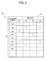
- Fig. 2 represents an example as to a television channel register table of the first embodiment of the present invention.
- a television channel register table 11 has registered channels 22 which are receivable for every area code 21.
- the area codes 21 are received by the portable telephone 1 from base stations for performing wireless communications, and indicate positional information of present places of the portable telephone 1.
- a television channel list screen which will be described in the next paragraph and corresponds to the area codes 21 are formed from the television channel register table 11, and then, is displayed on the display unit 8.
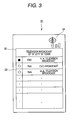
- Fig. 3 indicates an example of the television channel list screen of the first embodiment of the present invention.
- a present place 32 a television channel list table 33 receivable at the present place, a reception electric field level 34 of a television, and the like are displayed on the television channel list screen 31 which is displayed on the display unit 8.
- a reception electric field strength of a channel which is designated by, for example symbol, " ⁇ " is displayed in the reception electric field level 34 of the television.
- a television program which is broadcasted via a channel selected in the television channel list table 33 is displayed on the display unit 8, and sound is outputted from the sound output unit 9.
- Fig. 4 indicates a display example as to the display unit of the first embodiment of the present invention.
- Fig. 4(a) is a first display example of the display unit
- Fig. 4(b) is a second display example of the display unit.
- a received television broadcast 42, a reception electric field level 43 of the television broadcast, a reception electric field level 44 of a wireless communication with a base station, and the like are displayed.
- the reception electric field level 43 of the television is provided at a corner of the received television broadcast 42 on the display unit 41.
- both the reception electric field level 43 of the television broadcast and the reception electric field level 44 of the wireless communication are displayed on the display unit 41, electromagnetic wave conditions of the television broadcast and electromagnetic wave conditions of the wireless communication can be grasped at the same time.
- the display unit 45 of Fig. 4(b) the received television broadcast 42, the reception electric field level 43 of the television, and the like are displayed.
- the display unit 45 displays the reception electric field level 43 of the television broadcast by replacing the reception electric field level 44 of the wireless communication shown in Fig. 4(a) by this reception electric field level 43.
- the reception electric field levels 34 and 43 of the television broadcast show a broadcasting electromagnetic wave mark.
- Fig. 5 shows an enlarged diagram of a broadcasting electromagnetic wave mark of the first embodiment of the present invention.
- the broadcasting electromagnetic mark 51 is constituted by a broadcasting tower mark 52, and three antenna bars 53 having different lengths from each other.
- the broadcasting tower mark 51 shows that a reception electric field level indicated by the antenna bars 53 corresponds to a level for a broadcasting electromagnetic wave, which can be discriminated from a level for a wireless communication electromagnetic wave. Also, since the broadcasting tower mark 52 is displayed, this mark 52 indicates a broadcasting service area.
- reception electric field levels 34 and 43 of the television broadcast are indicated based upon high/low voltages of reception electric field strength signals (will be referred to as "RSSI signals" hereinafter) which indicate electric field strengths of received broadcast electromagnetic waves.
- RSSI signals reception electric field strength signals
- Fig. 6 is a flow chart for explaining process operations executed when a television broadcast is received by the portable telephone 1 according to the first embodiment of the present invention.
- the process operations by the portable telephone 1 are controlled by that the CPU 2 executes the control program 10 shown in Fig. 1.
- the wireless communication unit 5 transmits a position notification request with respect to a base station (S102) so as to receive an area code of the present place from the base station (S103).
- the television broadcast receiving unit 7 receives the television broadcast which is tuned to the selected channel, and measures a reception electric field strength of the received television broadcast.
- the display unit 8 displays a reception electric field level 43 based upon the reception electric field strength of the received television broadcast (S107), and displays television broadcast 42 on the display unit 41, and also the sound output unit 9 outputs sound (S108).
- the process operation is returned to S107 in which the television broadcast receiving unit 7 again receives television broadcast which is tuned to the switched channel, and measures a reception electric field strength of the newly received television broadcast.
- the display unit 8 displays a reception electric field level 43 based upon the reception electric field strength of the newly received television broadcast (S107), and displays the newly received television broadcast 42 on the display unit 41, and also, the sound output unit 9 outputs sound (S108).
- the process operation is returned to S107 in which the process operation for again measuring a reception electric field strength of the channel under display so as to output the reception electric level 43 of the television (S107).
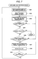
- Fig. 7 is a flow chart for explaining process operations of channel selecting operation by the portable telephone according to the first embodiment of the present invention.
- the area code 21 of the television channel register table 11 of Fig. 2 is retrieved so as to acquire a receivable channel 22 which has been registered in the same area code 21 as the area code received in the S103 of Fig. 6, and the television channel list table 33 shown in Fig. 3 is formed (S201), and then the formed television channel list screen 31 is displayed (S202).
- the process operation is returned to the S203 in which the television broadcast receiving unit 7 againmeasures a reception electric field strength of another channel, and again displays a reception electric field level based upon the re-measured reception electric field strength on the television channel list screen 31 (S203).
- reception electric field level displayed in the S203 exceeds a predetermined value (S206; NO)
- the process operation is again returned to the S203.
- a reception electric field strength of the channel designated by symbol " ⁇ " is again measured so as to again output a reception electric field level 34 of the television channel list screen 31 (S203).
- the process operation waits for an operation from the input unit 3, the process operations defined from the S203 to the S206 are repeatedly carried out.
- a position notification request is again transmitted from the wireless communication unit 5 with respect to the base station (S207) so as to again receive an area code from the base station (S208).
- the process operation is returned to the S203 in which such a process operation is carried out that a reception electric field strength of the channel designated by symbol " ⁇ " is againmeasured so as to again output the reception electric field level 34 of the television channel list screen 31 (S203).
- the process operation is returned to the S201 in which the area code 21 of the television channel register table 11 of Fig. 2 is retrieved so as to require a receivable channel 22 registered in the same area code 21 as the newly received area code, and a television channel list screen 31 is newly formed (S201), and this new television list screen 31 is displayed (S202).
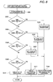
- FIG. 8 is a flow chart for describingprocess operations of displaying reception electric field levels in the portable telephone of the first embodiment of the present invention.
- the television broadcast receiving unit 7 of Fig. 1 is tuned to the designated channel so as to receive television broadcast electromagnetic waves, and measures a voltage of a reception electric field strength signal (will be referred to as "RSSI signal” hereinafter) indicative of an electric field strength of the receivedelectromagneticwaves (S301).
- RSSI signal a reception electric field strength signal
- A S302; YES
- the user of the portable telephone since the electric field strengths of the received television broadcast electromagnetic waves are displayed, the user of the portable telephone can simply confirm the reception condition of the television channel receivable at the present place.
- the channel selecting process operation of Fig. 7 executed in the portable telephone of the first embodiment of the present invention displays the television channel list screen 31 so as to select the channel
- the channel selecting process operation is not limited only to the method for selecting the channel from the television channel list screen 31.
- the receivable channels may be allocated to the ten-numeral keys and the various sorts of function keys of the input unit 3, and then, the channel may be selected by depressing the key.
- the television channel register table is retrieved based upon the positional information so as to acquire the receivable channel.
- the television channel register table 11 may be retrieved based upon such a positional information acquired by GPS (Global Positioning System) in order to acquire the receivable channel.
- GPS Global Positioning System
- a reception electric field level of a wireless communication may be alternatively displayed on the television channel list screen of Fig. 3.
- a portable telephone according to a second embodiment of the present invention will now be described in detail with reference to Fig. 9 to Fig. 13.
- the same reference numerals will be employed as those for denoting portions which have already been explained in the first embodiment, and therefore, explanations thereof are omitted.
- Fig. 9 is a block diagram for indicating an arrangement of a portable telephone according to the second embodiment of the present invention.
- the portable telephone 100 is arranged by containing a radio broadcast receiving unit 107 and a ROM 12.
- the radio broadcast receiving unit 107 receives a radio broadcast via a radio antenna 106 from a radio broadcasting tower.
- the ROM 12 stores thereinto a radio frequency register table 111.
- the CPU 2 executes such a process operation that a radio broadcast is received in response to an operation from the input unit 3 so as to display a reception electric field level of the radio broadcast.
- Fig. 10 represents an example as to a radio frequency register table of the second embodiment of the present invention.
- a radio frequency register table 111 has registered frequencies 122 which are receivable for every area code 121 by applying signs, for example, "o.”
- an area code "101” for instance, the receivable frequencies 122 of "78.0 MHz”, “79.0MHz”, and” “80.0 MHz” have been registered by applying the signs " ⁇ .”
- other frequencies 122 which cannot be received in the area code "101" are not registered, since these frequencies 122 have no sign " ⁇ .”
- An area code 121 indicates positional information as to a present place of the portable telephone 100, which is received from a base station to which the portable telephone 100 is communicated in a wireless manner.
- a radio frequency list screen corresponding to the area code 121 is formed from the radio frequency register table 111 so as to be displayed on the display unit 8.
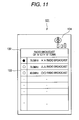
- Fig. 11 indicates an example of the radio frequency list screen of the second embodiment of the present invention.
- a present place 132 a radio frequency list table 133 receivable at the present places 132, and a reception electric field level 134 of a radio broadcast are displayed on the radio frequency list screen 131 which is displayed on the display unit 8.
- a reception electric field strength of a frequency which is designated by for example symbol " ⁇ " is displayed in the reception electric field level 134 of the radio broadcast. Sound of a radio program which is broadcasted at a frequency selected in the radio frequency list table 133 is outputted from the sound output unit 9.
- the display unit 8 may display any one of screens during radio broadcasting operation, for example, a reception electric field level of a radio broadcast is outputted such as the reception electric field level 43 of the television broadcast shown in Fig. 4 of the first embodiment.
- a reception electric field level of a radio broadcast is outputted such as the reception electric field level 43 of the television broadcast shown in Fig. 4 of the first embodiment.
- both a reception electric field level of a radio broadcast and a reception electric field level of a wireless communication may be displayed, and also, as represented in Fig. 4 (b), only a reception electric field level of a radio broadcast may be displayed.
- a reception electric field level of a radio broadcast may be displayed by the broadcasting electromagnetic wave mark 51 of Fig. 5 so as to be distinguishable from an electromagnetic wave condition indication of a wireless communication.
- Fig. 12 is a flow chart for explaining process operations executed when a radio broadcast is received by the portable telephone according to the second embodiment of the present invention. It should be understood that process operations defined from 5201 to S104, and a process operation defined in S111 are executed by the same process operations of the process flow diagram when the television broadcast is received by the portable telephone of the first embodiment shown in Fig. 6. Since a radio broadcast has not yet been received (S404; NO and S405; NO), when the user selects a radio frequency in a frequency selecting process operation (S406), the radio broadcast receiving unit 107 receives a radio broadcast which is tuned to the selected frequency so as to measure a reception electric field strength of the received radio broadcast. The display unit 8 displays a reception electric field level based upon the reception electric field strength of the received radio broadcast (S407), and the sound output unit 9 outputs the radio broadcast (S408).
- the process operation is returned to S407.
- the radio broadcast receiving unit 107 again receives a radio broadcast which is tuned to the switched frequency 122 so as to measure a reception electric field strength of the newly received radio broadcast.
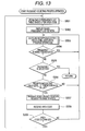
- Fig. 13 is a flow chart for explaining process operations of frequency selecting operation by the portable telephone according to the second embodiment of the present invention.
- the area code 121 of the radio frequency register table 111 of Fig. 10 is retrieved so as to acquire a receivable frequency 122 which has been registered in the same area code 121 as the area code received in the S403 of Fig. 12, and the radio frequency list table 133 shown in Fig. 11 is formed (S501), and then the formed radio frequency list screen 131 is displayed (S502).
- the process operation is returned to the S503 in which the radio broadcast receiving unit 107 againmeasures a reception electric field strength of another frequency 122, and again displays a reception electric field level based upon the re-measured reception electric field strength on the radio frequency list screen 131 (S503).
- reception electric field level displaying process operations of S407 and S503 a similar process operation to that of Fig. 8 is carried out by employing an electric field strength which is detected by an electric field strength detecting circuit (not shown) provided in the radio broadcast receiving unit 107, and then, a reception electric field level of the radio broadcast is displayed on the display unit 8.
- the user of the portable telephone since the electric field strength of the received radio broadcast is displayed, the user of the portable telephone can simply confirm the reception conditions of the radio broadcast receivable at the present place.
- the portable telephone equipped with the television broadcast receiving function has been explained in the first embodiment of the present invention, whereas the portable telephone equipped with the radio broadcast receiving function has been described in the second embodiment of the present invention.
- the present invention maybe applied to such a portable terminal apparatus as a portable telephone equipped with both the television broadcast receiving function and the radio broadcast receiving function.
- the portable terminal apparatus of the present invention owns such an effect that the reception conditions of the broadcast electromagnetic waves distributed from the broadcasting stations can be quantitatively and easily confirmed, and is useful for a portable terminal apparatus having either a television broadcast receiving function or a radio broadcast receiving function.
Landscapes
- Engineering & Computer Science (AREA)
- Signal Processing (AREA)
- Multimedia (AREA)
- Computer Networks & Wireless Communication (AREA)
- Human Computer Interaction (AREA)
- General Engineering & Computer Science (AREA)
- Databases & Information Systems (AREA)
- Mobile Radio Communication Systems (AREA)
- Telephone Function (AREA)
- Testing, Inspecting, Measuring Of Stereoscopic Televisions And Televisions (AREA)
- Transceivers (AREA)
- Circuits Of Receivers In General (AREA)
Applications Claiming Priority (2)
| Application Number | Priority Date | Filing Date | Title |
|---|---|---|---|
| JP2004253941A JP4503400B2 (ja) | 2004-09-01 | 2004-09-01 | 携帯端末装置 |
| PCT/JP2005/016014 WO2006025491A1 (ja) | 2004-09-01 | 2005-09-01 | 携帯端末装置 |
Publications (1)
| Publication Number | Publication Date |
|---|---|
| EP1791264A1 true EP1791264A1 (en) | 2007-05-30 |
Family
ID=36000140
Family Applications (1)
| Application Number | Title | Priority Date | Filing Date |
|---|---|---|---|
| EP05781332A Withdrawn EP1791264A1 (en) | 2004-09-01 | 2005-09-01 | Mobile terminal apparatus |
Country Status (4)
| Country | Link |
|---|---|
| US (1) | US20070287379A1 (enExample) |
| EP (1) | EP1791264A1 (enExample) |
| JP (1) | JP4503400B2 (enExample) |
| WO (1) | WO2006025491A1 (enExample) |
Cited By (4)
| Publication number | Priority date | Publication date | Assignee | Title |
|---|---|---|---|---|
| EP2066117A2 (en) | 2007-11-30 | 2009-06-03 | LG Electronics Inc. | Mobile terminal and channel scanning method thereof |
| US20090318143A1 (en) * | 2008-06-23 | 2009-12-24 | Lg Electronics Inc. | Mobile terminal and method of managing channel list therein |
| EP2091245A3 (en) * | 2008-02-15 | 2010-01-20 | Avermedia Technologies, Inc. | Digital television signal-receiving device with signal strength showing function |
| EP1919109A3 (en) * | 2006-10-26 | 2012-04-11 | LG Electronics Inc. | Method for displaying broadcast-related information in a mobile terminal capable of broadcast reception and mobile terminal for implementing the method |
Families Citing this family (19)
| Publication number | Priority date | Publication date | Assignee | Title |
|---|---|---|---|---|
| US8116748B2 (en) | 2006-12-14 | 2012-02-14 | At&T Intellectual Property I, Lp | Management of locations of group members via mobile communications devices |
| US8160548B2 (en) * | 2006-12-15 | 2012-04-17 | At&T Intellectual Property I, Lp | Distributed access control and authentication |
| US7646297B2 (en) | 2006-12-15 | 2010-01-12 | At&T Intellectual Property I, L.P. | Context-detected auto-mode switching |
| US8566602B2 (en) | 2006-12-15 | 2013-10-22 | At&T Intellectual Property I, L.P. | Device, system and method for recording personal encounter history |
| US20080146250A1 (en) * | 2006-12-15 | 2008-06-19 | Jeffrey Aaron | Method and System for Creating and Using a Location Safety Indicator |
| US8649798B2 (en) * | 2007-01-25 | 2014-02-11 | At&T Intellectual Property I, L.P. | Methods and devices for attracting groups based upon mobile communications device location |
| US8787884B2 (en) * | 2007-01-25 | 2014-07-22 | At&T Intellectual Property I, L.P. | Advertisements for mobile communications devices via pre-positioned advertisement components |
| US8199003B2 (en) * | 2007-01-30 | 2012-06-12 | At&T Intellectual Property I, Lp | Devices and methods for detecting environmental circumstances and responding with designated communication actions |
| US8335504B2 (en) * | 2007-08-23 | 2012-12-18 | At&T Intellectual Property I, Lp | Methods, devices and computer readable media for providing quality of service indicators |
| US8200200B1 (en) * | 2008-02-04 | 2012-06-12 | Sprint Communications Company L.P. | Localized mobile digital TV |
| KR101507795B1 (ko) * | 2008-05-09 | 2015-04-03 | 엘지전자 주식회사 | 이동 단말기 및 이것의 채널 표시 방법 |
| US8774093B2 (en) | 2010-06-30 | 2014-07-08 | E.F. Johnson Company | System and method for providing mobility management and out-of-coverage indication in a conventional land mobile radio system |
| US8699369B2 (en) | 2010-08-14 | 2014-04-15 | E.F. Johnson Company | Hybrid land mobile radio system incorporating mobility management and out-of-coverage indication |
| US20120196595A1 (en) * | 2011-11-03 | 2012-08-02 | Perry Ii Jack F | Broadcast area identification |
| US20130117774A1 (en) * | 2011-11-03 | 2013-05-09 | Syncbak, Inc. | Secure broadcast area identification |
| US20120196596A1 (en) * | 2011-11-03 | 2012-08-02 | Perry Ii Jack F | Broadcast area identification |
| US20140044005A1 (en) * | 2012-01-19 | 2014-02-13 | Xirrus, Inc. | System and method for conducting wireless site surveys using wireless network design criteria |
| JP5980017B2 (ja) * | 2012-07-06 | 2016-08-31 | 株式会社Nttドコモ | ユーザ装置及びアンテナピクト表示方法 |
| US10432331B1 (en) * | 2018-12-26 | 2019-10-01 | Jebsee Electronics Co., Ltd. | Wireless signal level indicator |
Family Cites Families (17)
| Publication number | Priority date | Publication date | Assignee | Title |
|---|---|---|---|---|
| JPH0270183A (ja) * | 1988-09-06 | 1990-03-09 | Seiko Epson Corp | テレビの電界強度表示回路 |
| JP2820507B2 (ja) * | 1990-06-14 | 1998-11-05 | 松下電器産業株式会社 | 移動体受信装置 |
| US5842119A (en) * | 1993-02-05 | 1998-11-24 | Emerson; Harry Edwin | Radio scanner and display system |
| US5613232A (en) * | 1993-03-12 | 1997-03-18 | Alinco Incorporated | Receiver apparatus comprising display means for displaying signal strengths of signals having a plurality of frequencies, and display apparatus for use in receiver apparatus |
| JP2546182B2 (ja) * | 1994-05-24 | 1996-10-23 | 日本電気株式会社 | 無線システム |
| US20030097654A1 (en) * | 1998-06-05 | 2003-05-22 | Franken Kenneth A. | System and method of geographic authorization for television and radio programming distributed by multiple delivery mechanisms |
| JP3485474B2 (ja) * | 1998-10-06 | 2004-01-13 | 株式会社ケンウッド | ディジタル放送受信機 |
| US6725022B1 (en) * | 1999-09-22 | 2004-04-20 | Motorola, Inc. | Method and apparatus for enabling the selection of content on a wireless communication device |
| JP2002044036A (ja) * | 2000-07-26 | 2002-02-08 | Sharp Corp | 電波レベル表示方法 |
| JP2002064613A (ja) * | 2000-08-18 | 2002-02-28 | Hitachi Kokusai Electric Inc | 携帯無線端末装置及び携帯無線端末装置の接続方法及び携帯無線端末装置の切断方法 |
| US6959192B1 (en) * | 2000-11-06 | 2005-10-25 | Agere Systems Inc. | System and method for updating stored information portable electronic devices based on geographic location |
| JP4088096B2 (ja) * | 2002-04-16 | 2008-05-21 | 株式会社日立製作所 | デジタル放送用コンテンツ配信局及びコンテンツ配信方法 |
| JP4026403B2 (ja) * | 2002-04-30 | 2007-12-26 | 日本電気株式会社 | 放送鉄塔選択方法、放送鉄塔選択プログラム及び放送受信装置 |
| JP4113473B2 (ja) * | 2002-11-14 | 2008-07-09 | シャープ株式会社 | デジタル放送受信装置 |
| JP4054686B2 (ja) * | 2003-01-20 | 2008-02-27 | シャープ株式会社 | デジタル放送受信装置 |
| WO2004095725A1 (ja) * | 2003-04-21 | 2004-11-04 | Matsushita Electric Industrial Co. Ltd. | 高周波信号レベル検出装置及びそれを用いた高周波信号受信装置 |
| JP2005260758A (ja) * | 2004-03-12 | 2005-09-22 | Hitachi Ltd | 携帯端末、ディジタルデータ配信サーバ、及びデータ送/受信システム |
-
2004
- 2004-09-01 JP JP2004253941A patent/JP4503400B2/ja not_active Expired - Fee Related
-
2005
- 2005-09-01 EP EP05781332A patent/EP1791264A1/en not_active Withdrawn
- 2005-09-01 US US11/574,136 patent/US20070287379A1/en not_active Abandoned
- 2005-09-01 WO PCT/JP2005/016014 patent/WO2006025491A1/ja not_active Ceased
Non-Patent Citations (1)
| Title |
|---|
| See references of WO2006025491A1 * |
Cited By (8)
| Publication number | Priority date | Publication date | Assignee | Title |
|---|---|---|---|---|
| EP1919109A3 (en) * | 2006-10-26 | 2012-04-11 | LG Electronics Inc. | Method for displaying broadcast-related information in a mobile terminal capable of broadcast reception and mobile terminal for implementing the method |
| EP2066117A2 (en) | 2007-11-30 | 2009-06-03 | LG Electronics Inc. | Mobile terminal and channel scanning method thereof |
| EP2066117A3 (en) * | 2007-11-30 | 2009-11-11 | LG Electronics Inc. | Mobile terminal and channel scanning method thereof |
| US8170499B2 (en) | 2007-11-30 | 2012-05-01 | Lg Electronics Inc. | Mobile terminal and channel scanning method thereof |
| KR101448621B1 (ko) * | 2007-11-30 | 2014-10-08 | 엘지전자 주식회사 | 단말기 및 이것의 채널 스캔 방법 |
| EP2091245A3 (en) * | 2008-02-15 | 2010-01-20 | Avermedia Technologies, Inc. | Digital television signal-receiving device with signal strength showing function |
| US20090318143A1 (en) * | 2008-06-23 | 2009-12-24 | Lg Electronics Inc. | Mobile terminal and method of managing channel list therein |
| EP2139231A1 (en) * | 2008-06-23 | 2009-12-30 | Lg Electronics Inc. | Mobile terminal and method of managing channel list therein |
Also Published As
| Publication number | Publication date |
|---|---|
| JP4503400B2 (ja) | 2010-07-14 |
| WO2006025491A1 (ja) | 2006-03-09 |
| US20070287379A1 (en) | 2007-12-13 |
| JP2006074324A (ja) | 2006-03-16 |
Similar Documents
| Publication | Publication Date | Title |
|---|---|---|
| US20070287379A1 (en) | Mobile Terminal Apparatus | |
| US6584320B1 (en) | Server based provision of map data to terminal devices | |
| US7680459B2 (en) | FM transmission system and method | |
| WO2003105458A3 (en) | Digital video broadcast-terrestrial (dvb-t) receiver interoperable with a gsm transmitter in a non-interfering manner using classmark change procedure | |
| KR100814490B1 (ko) | 무선 디바이스 | |
| WO2009076027A2 (en) | Method and apparatus for selecting a radio channel for transmitting an audio signal to a radio local receiver | |
| US5613232A (en) | Receiver apparatus comprising display means for displaying signal strengths of signals having a plurality of frequencies, and display apparatus for use in receiver apparatus | |
| US7761117B2 (en) | Apparatus and method for indicating the kind of current communication service of dual mode mobile terminal | |
| JPH08162909A (ja) | 端末装置 | |
| US8611899B2 (en) | Base station apparatus, wireless communication terminal apparatus, communication method and computer readable medium thereof | |
| KR101105771B1 (ko) | 방송수신 단말기 및 그 동작 제어방법 | |
| KR100270704B1 (ko) | 음영지도 작성을 위한 무선통신 시스템 및 방법 | |
| JPH09307942A (ja) | 移動局装置 | |
| JP2005286864A (ja) | 移動通信端末、位置測位サーバ、位置測位システム、及び位置測位方法 | |
| KR20000013464A (ko) | 홈과 로컬 지역의 현재시간 표시방법 | |
| JP2008294919A (ja) | 無線中継装置 | |
| JP2008177634A (ja) | 移動通信端末及び通信品質の表示方法並びに制御プログラム | |
| JP2007208349A (ja) | 無線機用テストシステム | |
| JP4944453B2 (ja) | 移動体通信端末、および、プログラム | |
| KR100295442B1 (ko) | 듀얼밴드무선단말기에서채널자동선택방법 | |
| JP2004312092A (ja) | 無線通信装置および無線通信装置のチャネル選択方法 | |
| KR101158049B1 (ko) | 이동 단말기의 채널 정보 제공 방법 및 채널 정보 편집 방법 | |
| JP2993329B2 (ja) | コードレス電話装置 | |
| KR100350783B1 (ko) | Dect시스템에서 이동국의 셀 영역 이탈 경고방법 | |
| KR100770888B1 (ko) | Dmb 단말기에서 매너 지역 알림 방법 |
Legal Events
| Date | Code | Title | Description |
|---|---|---|---|
| PUAI | Public reference made under article 153(3) epc to a published international application that has entered the european phase |
Free format text: ORIGINAL CODE: 0009012 |
|
| 17P | Request for examination filed |
Effective date: 20070227 |
|
| AK | Designated contracting states |
Kind code of ref document: A1 Designated state(s): DE FR GB |
|
| RBV | Designated contracting states (corrected) |
Designated state(s): DE FR GB |
|
| DAX | Request for extension of the european patent (deleted) | ||
| RBV | Designated contracting states (corrected) |
Designated state(s): DE FR GB |
|
| RAP1 | Party data changed (applicant data changed or rights of an application transferred) |
Owner name: PANASONIC CORPORATION |
|
| STAA | Information on the status of an ep patent application or granted ep patent |
Free format text: STATUS: THE APPLICATION HAS BEEN WITHDRAWN |
|
| 18W | Application withdrawn |
Effective date: 20121001 |