EP1790280B1 - Method of assembling an in-vivo imaging device - Google Patents
Method of assembling an in-vivo imaging device Download PDFInfo
- Publication number
- EP1790280B1 EP1790280B1 EP06124509A EP06124509A EP1790280B1 EP 1790280 B1 EP1790280 B1 EP 1790280B1 EP 06124509 A EP06124509 A EP 06124509A EP 06124509 A EP06124509 A EP 06124509A EP 1790280 B1 EP1790280 B1 EP 1790280B1
- Authority
- EP
- European Patent Office
- Prior art keywords
- sleeve
- circuit board
- present
- battery
- domes
- Prior art date
- Legal status (The legal status is an assumption and is not a legal conclusion. Google has not performed a legal analysis and makes no representation as to the accuracy of the status listed.)
- Active
Links
- 238000000034 method Methods 0.000 title claims abstract description 48
- 238000011503 in vivo imaging Methods 0.000 title claims abstract description 27
- 230000003287 optical effect Effects 0.000 claims abstract description 52
- 238000003466 welding Methods 0.000 claims description 9
- 238000002844 melting Methods 0.000 claims description 3
- 230000008018 melting Effects 0.000 claims description 3
- 238000004026 adhesive bonding Methods 0.000 claims description 2
- 238000005304 joining Methods 0.000 claims description 2
- 239000002775 capsule Substances 0.000 description 14
- 238000005286 illumination Methods 0.000 description 14
- 238000001727 in vivo Methods 0.000 description 13
- 238000003384 imaging method Methods 0.000 description 11
- 210000001035 gastrointestinal tract Anatomy 0.000 description 7
- 230000005540 biological transmission Effects 0.000 description 6
- 238000004891 communication Methods 0.000 description 4
- 238000003860 storage Methods 0.000 description 3
- 235000014676 Phragmites communis Nutrition 0.000 description 2
- 238000012986 modification Methods 0.000 description 2
- 230000004048 modification Effects 0.000 description 2
- 238000012545 processing Methods 0.000 description 2
- 230000001953 sensory effect Effects 0.000 description 2
- NDVLTYZPCACLMA-UHFFFAOYSA-N silver oxide Chemical compound [O-2].[Ag+].[Ag+] NDVLTYZPCACLMA-UHFFFAOYSA-N 0.000 description 2
- 239000001733 1,4-Heptonolactone Substances 0.000 description 1
- 239000002970 Calcium lactobionate Substances 0.000 description 1
- WHXSMMKQMYFTQS-UHFFFAOYSA-N Lithium Chemical compound [Li] WHXSMMKQMYFTQS-UHFFFAOYSA-N 0.000 description 1
- 239000000654 additive Substances 0.000 description 1
- 238000005452 bending Methods 0.000 description 1
- 239000003990 capacitor Substances 0.000 description 1
- 150000001875 compounds Chemical group 0.000 description 1
- 238000010586 diagram Methods 0.000 description 1
- 238000001839 endoscopy Methods 0.000 description 1
- 229910052744 lithium Inorganic materials 0.000 description 1
- 238000012544 monitoring process Methods 0.000 description 1
- 238000004806 packaging method and process Methods 0.000 description 1
- 238000012805 post-processing Methods 0.000 description 1
- 229910001923 silver oxide Inorganic materials 0.000 description 1
- 229910000679 solder Inorganic materials 0.000 description 1
- 239000000126 substance Chemical group 0.000 description 1
- 238000006467 substitution reaction Methods 0.000 description 1
Images


Classifications
-
- A—HUMAN NECESSITIES
- A61—MEDICAL OR VETERINARY SCIENCE; HYGIENE
- A61B—DIAGNOSIS; SURGERY; IDENTIFICATION
- A61B1/00—Instruments for performing medical examinations of the interior of cavities or tubes of the body by visual or photographical inspection, e.g. endoscopes; Illuminating arrangements therefor
- A61B1/04—Instruments for performing medical examinations of the interior of cavities or tubes of the body by visual or photographical inspection, e.g. endoscopes; Illuminating arrangements therefor combined with photographic or television appliances
- A61B1/042—Instruments for performing medical examinations of the interior of cavities or tubes of the body by visual or photographical inspection, e.g. endoscopes; Illuminating arrangements therefor combined with photographic or television appliances characterised by a proximal camera, e.g. a CCD camera
-
- A—HUMAN NECESSITIES
- A61—MEDICAL OR VETERINARY SCIENCE; HYGIENE
- A61B—DIAGNOSIS; SURGERY; IDENTIFICATION
- A61B1/00—Instruments for performing medical examinations of the interior of cavities or tubes of the body by visual or photographical inspection, e.g. endoscopes; Illuminating arrangements therefor
- A61B1/00064—Constructional details of the endoscope body
- A61B1/0011—Manufacturing of endoscope parts
-
- A—HUMAN NECESSITIES
- A61—MEDICAL OR VETERINARY SCIENCE; HYGIENE
- A61B—DIAGNOSIS; SURGERY; IDENTIFICATION
- A61B1/00—Instruments for performing medical examinations of the interior of cavities or tubes of the body by visual or photographical inspection, e.g. endoscopes; Illuminating arrangements therefor
- A61B1/00163—Optical arrangements
- A61B1/00174—Optical arrangements characterised by the viewing angles
- A61B1/00181—Optical arrangements characterised by the viewing angles for multiple fixed viewing angles
-
- A—HUMAN NECESSITIES
- A61—MEDICAL OR VETERINARY SCIENCE; HYGIENE
- A61B—DIAGNOSIS; SURGERY; IDENTIFICATION
- A61B1/00—Instruments for performing medical examinations of the interior of cavities or tubes of the body by visual or photographical inspection, e.g. endoscopes; Illuminating arrangements therefor
- A61B1/04—Instruments for performing medical examinations of the interior of cavities or tubes of the body by visual or photographical inspection, e.g. endoscopes; Illuminating arrangements therefor combined with photographic or television appliances
- A61B1/041—Capsule endoscopes for imaging
-
- A—HUMAN NECESSITIES
- A61—MEDICAL OR VETERINARY SCIENCE; HYGIENE
- A61B—DIAGNOSIS; SURGERY; IDENTIFICATION
- A61B1/00—Instruments for performing medical examinations of the interior of cavities or tubes of the body by visual or photographical inspection, e.g. endoscopes; Illuminating arrangements therefor
- A61B1/04—Instruments for performing medical examinations of the interior of cavities or tubes of the body by visual or photographical inspection, e.g. endoscopes; Illuminating arrangements therefor combined with photographic or television appliances
- A61B1/05—Instruments for performing medical examinations of the interior of cavities or tubes of the body by visual or photographical inspection, e.g. endoscopes; Illuminating arrangements therefor combined with photographic or television appliances characterised by the image sensor, e.g. camera, being in the distal end portion
- A61B1/051—Details of CCD assembly
-
- A—HUMAN NECESSITIES
- A61—MEDICAL OR VETERINARY SCIENCE; HYGIENE
- A61B—DIAGNOSIS; SURGERY; IDENTIFICATION
- A61B1/00—Instruments for performing medical examinations of the interior of cavities or tubes of the body by visual or photographical inspection, e.g. endoscopes; Illuminating arrangements therefor
- A61B1/06—Instruments for performing medical examinations of the interior of cavities or tubes of the body by visual or photographical inspection, e.g. endoscopes; Illuminating arrangements therefor with illuminating arrangements
- A61B1/0607—Instruments for performing medical examinations of the interior of cavities or tubes of the body by visual or photographical inspection, e.g. endoscopes; Illuminating arrangements therefor with illuminating arrangements for annular illumination
-
- A—HUMAN NECESSITIES
- A61—MEDICAL OR VETERINARY SCIENCE; HYGIENE
- A61B—DIAGNOSIS; SURGERY; IDENTIFICATION
- A61B1/00—Instruments for performing medical examinations of the interior of cavities or tubes of the body by visual or photographical inspection, e.g. endoscopes; Illuminating arrangements therefor
- A61B1/06—Instruments for performing medical examinations of the interior of cavities or tubes of the body by visual or photographical inspection, e.g. endoscopes; Illuminating arrangements therefor with illuminating arrangements
- A61B1/0661—Endoscope light sources
- A61B1/0676—Endoscope light sources at distal tip of an endoscope
-
- A—HUMAN NECESSITIES
- A61—MEDICAL OR VETERINARY SCIENCE; HYGIENE
- A61B—DIAGNOSIS; SURGERY; IDENTIFICATION
- A61B1/00—Instruments for performing medical examinations of the interior of cavities or tubes of the body by visual or photographical inspection, e.g. endoscopes; Illuminating arrangements therefor
- A61B1/06—Instruments for performing medical examinations of the interior of cavities or tubes of the body by visual or photographical inspection, e.g. endoscopes; Illuminating arrangements therefor with illuminating arrangements
- A61B1/0661—Endoscope light sources
- A61B1/0684—Endoscope light sources using light emitting diodes [LED]
-
- A—HUMAN NECESSITIES
- A61—MEDICAL OR VETERINARY SCIENCE; HYGIENE
- A61B—DIAGNOSIS; SURGERY; IDENTIFICATION
- A61B1/00—Instruments for performing medical examinations of the interior of cavities or tubes of the body by visual or photographical inspection, e.g. endoscopes; Illuminating arrangements therefor
- A61B1/273—Instruments for performing medical examinations of the interior of cavities or tubes of the body by visual or photographical inspection, e.g. endoscopes; Illuminating arrangements therefor for the upper alimentary canal, e.g. oesophagoscopes, gastroscopes
-
- H—ELECTRICITY
- H04—ELECTRIC COMMUNICATION TECHNIQUE
- H04N—PICTORIAL COMMUNICATION, e.g. TELEVISION
- H04N23/00—Cameras or camera modules comprising electronic image sensors; Control thereof
- H04N23/50—Constructional details
- H04N23/555—Constructional details for picking-up images in sites, inaccessible due to their dimensions or hazardous conditions, e.g. endoscopes or borescopes
-
- A—HUMAN NECESSITIES
- A61—MEDICAL OR VETERINARY SCIENCE; HYGIENE
- A61B—DIAGNOSIS; SURGERY; IDENTIFICATION
- A61B1/00—Instruments for performing medical examinations of the interior of cavities or tubes of the body by visual or photographical inspection, e.g. endoscopes; Illuminating arrangements therefor
- A61B1/00002—Operational features of endoscopes
- A61B1/00011—Operational features of endoscopes characterised by signal transmission
- A61B1/00016—Operational features of endoscopes characterised by signal transmission using wireless means
-
- A—HUMAN NECESSITIES
- A61—MEDICAL OR VETERINARY SCIENCE; HYGIENE
- A61B—DIAGNOSIS; SURGERY; IDENTIFICATION
- A61B5/00—Measuring for diagnostic purposes; Identification of persons
- A61B5/07—Endoradiosondes
- A61B5/073—Intestinal transmitters
Definitions
- the present invention relates to a method of assembling an in-vivo imaging device for capsule endoscopy, as defined in claim 1.
- Such in-vivo sensing devices may be in the form of swallowable or ingestible capsules which may move through a body lumen.
- the in-vivo sensing device may include, for example, an imaging system for obtaining images from inside the body lumen, such as the gastrointestinal (GI) tract as it moves through it.
- the imaging system may include, for example, an illumination unit, such as a set of light emitting diodes (LEDs), or other suitable light sources, an imaging sensor and an optical system, which focuses the images onto the imaging sensor.
- a transmitter and antenna may be included for transmitting the images signals to an external data recorder.
- a power source such as one or more batteries, may also be included for powering the various electrical and electronic components.
- the imaging system, transmitter, antenna, batteries and other components are assembled in the in-vivo sensing device's housing in a compact and secure manner, which takes into account the cooperation between the electrical and electronic components and the required optical properties of the in-vivo sensing device. It is known from US 2004/027459 to provide an in-vivo imaging device having a single optical head, and from US 2005/043583 to provide such a device with two optical heads. US 2003/020810 discloses a capsule-type device including a battery.
- the comprises the further steps of:
- the step of placing at least one battery in a second sleeve is performed prior to the step folding the circuit board.
- At least one battery is placed in the first sleeve.
- the first sleeve is placed between the two optical heads with the flexible portion passing between the two opposing open ends prior to folding the circuit board; and at least one battery is placed in the first sleeve after positioning one of the optical heads over one of the open ends.
- the domes are joined to the first sleeve by a process chosen from the following group: gluing, fraction fitting, press fitting, snap fitting, laser welding, laser melting, spin welding, and ultra sonic welding.
- FIGs. 1A and 1B schematically illustrate an in vivo imaging device and system according to some embodiments of the present invention
- Fig. 2 schematically illustrates a perspective view of an in vivo imaging device according to some embodiments of the present invention in a body lumen;
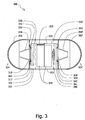
- Fig. 3 schematically illustrates a longitudinal cross section of an in vivo imaging device according to some embodiments of the present invention
- Figs. 4A and 4B schematically illustrate a top view and a bottom view, respectively, of a circuit board, in accordance with an embodiment of the present invention
- FIG. 5A schematically illustrates a connecting sleeve, according to some embodiments of the present invention
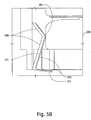
- Fig. 5B schematically illustrates a side view, of a battery contact, in accordance with some embodiments of the present invention
- Fig. 6A is a schematic flow-chart of a method of assembling an in vivo imaging device, in accordance with some embodiments of the invention.
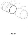
- FIGS. 6B -6F schematically illustrate a method of assembling an in vivo imaging device, in accordance with some embodiments of the invention
- Fig. 6G is a schematic flow-chart of a method of assembling an in vivo imaging device, in accordance with some embodiments of the invention.
- Fig. 7A is a schematic flow-chart of another method of assembling an in vivo imaging device, in accordance with some embodiments of the present invention.
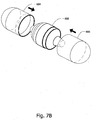
- Fig. 7B schematically illustrates a method of assembling an in vivo imaging device, in accordance with some embodiments of the present invention.
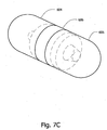
- Fig. 7C schematically illustrates a perspective view of the in vivo imaging device shown in Fig. 7B in an assembled state.
- embodiments of the present invention may be directed to an autonomous, typically ingestible in-vivo device. Other embodiments need not be ingestible.
- Devices or systems according to embodiments of the present invention may be similar to embodiments described in International Application WO 01/65995 and/or in U.S. Patent No. 5,604,531 , each of which are assigned to the common assignee of the present invention.
- a receiving and/or display system suitable for use with embodiments of the present invention may also be similar to embodiments described in WO 01/65995 and/or in U.S. Patent Number 5,604,531 .
- Devices and systems as described herein may have other configurations and other sets of components.
- the system may include a device 40 having an imager 36 and/or 36' (such as for example a CMOS, a CCD, etc.), an optical system which may include lens holder 32 and/or 32', lenses and other optical elements and illumination sources 34 such as one or more LEDs (Light Emitting Diode), and/or OLEDs (Organic LED) or other suitable illumination sources.
- an imager 36 and/or 36' such as for example a CMOS, a CCD, etc.
- an optical system which may include lens holder 32 and/or 32', lenses and other optical elements and illumination sources 34 such as one or more LEDs (Light Emitting Diode), and/or OLEDs (Organic LED) or other suitable illumination sources.
- the imager, optical system and light source are positioned behind a viewing window 30.
- Viewing window 30 may be a transparent elongated dome.
- the device may include a power source such as silver oxide batteries, lithium batteries, other suitable electrochemical cells having a high energy density, or the like.
- a power source such as silver oxide batteries, lithium batteries, other suitable electrochemical cells having a high energy density, or the like.
- Other power sources may be used.
- an external power source may be used to transmit power to device 40.
- an additional sensor may be included in the device, for example, pH, temperature, pressure or other physiological parameter sensors. Other components or sensors may also be included.
- a processor may be included in the device which may be for example capable of processing signals that are received by device 40 into for example command or control signals that may control, activate, deactivate or otherwise alter an operative state of components that may be included in device 40.
- the transceiver 31 may be a transmitter or a receiver or both that may be capable of receiving wireless signals and transmitting wireless signals; in some embodiments only transmission (for example, transmission of image data from imagers 36 and/or 36') may occur. Transceiver 31 may also have other functions. In some embodiments, transceiver 31 and the processor may be or may be included in a single integrated circuit. Device 40 may include antenna that may be operably attached to transceiver 31. In some embodiments, the antenna may be used for, or in the performance of, both the receipt and transmission of wireless signals by transceiver 31. In other embodiments there may be more than one antenna. In some embodiments, device 40 may transmit but not receive signals. An additional sensor or other components need not necessarily be included.
- device 40 may include two optical units. Each optical unit may include, for example, the transparent elongated dome 30 behind which are situated illumination sources 34, lens holders 32, 32' and imager 36, 36'.
- device 40 is capable of simultaneously obtaining images of the body lumen, for example, the GI tract, from two ends of the device.
- device 40 may be a cylindrical capsule having a front end and a rear end, which is capable of passing the entire GI tract. The front and rear ends may define a longitudinal direction and a longitudinal axis of the device 40.
- the lens holders 32, 32' and imagers 36, 36' may be located along the longitudinal axis.
- the imagers 36, 36' may be perpendicular to the longitudinal axis.
- the system in a cylindrical capsule can image the GI tract in the front and in the rear of the capsule.
- the images may be transmitted simultaneously or serially and may be displayed separately or as a single combined image.
- top, bottom, front, rear, over, above, etc. are considered relative terms descriptive of, for example, when the imaging device 40 is in a specific orientation relative to the viewer or the relative position of components of the device.
- the device 40 may include one or more light blockers such as light blockers 33 and 33' which may include a suitable structure to reduce backscatter.
- the light blocker may be formed and/or shaped such that it blocks stray light from reaching and/or flooding the imagers, such as imager 36 and imager 36'.
- the optical system in the device 40 may enable a wide field of view 37.
- Fig. 1B is a schematic illustration of an in-vivo imaging system in accordance with some embodiments of the present invention.
- the receiver 90 and possibly a transmitter External to device 40 may be the receiver 90 and possibly a transmitter.
- Receiver 90 and a possible transmitter may be housed or included in the same housing or unit, or may be housed in one or more separate units.
- a transmitter and receiver may be housed in a portable unit that may be carried or worn by a patient and/or may be integrated into a transceiver.
- Receiver 90 may be connected to and/or in electrical communication with a processor 92 which may process, for example, data signals such as, for example, sensory or image data signals that are received from device 40 and/or control data received from device 40.
- receiver 90 may be operably connected to a monitor/display 93 and/or a storage system 91 that may display and/or store the image or other sensory data collected and transmitted by device 40.
- Processor 92 may analyze data received by receiver 90 and may be in communication with storage system 91, transferring image data (which may be stored and transferred as for example frame data) or other data to and from storage system 91.
- Processor 92 may also provide the analyzed data to display 93 where a user may view the images.
- Display 93 may present or display the data such as, for example, image frame data or video data of, for example, the gastro-intestinal (GI) tract or other body lumen.
- processor 92 may be configured for real time processing and/or for post processing to be performed. Other monitoring and receiving systems may be used.
- a transmitter may typically be connected to and/or in electrical communication with processor 92.
- Processor 92 may function, at least partially as a controller and/or include, for example, a controller to process, for example, control commands to device 40 via the transmitter.
- signals other than control commands may be processed by processor 92 with, for example, the controller and transmitted via the transmitter.
- the controller and processor may be separate units that may be in electrical communication with each other.
- control commands generated, for example, by the controller may be based on data received by the receiver 90 and processed by processor 92.
- control commands generated, by the controller may be based on, user input data, for example, a patient or external operator may for example, initiate the transmission of a wireless signal and/or command from, for example, the transmitter to transceiver 31.
- control commands may be based on both user input data and data receiver and/or processed by processor 92.
- transceiver 31 may be a half duplex transceiver where the transceiver 31 alternates from transmitting to receiving, e.g. via time division multiple access (TDMA).
- TDMA time division multiple access
- the transmission rate to the external receiver 90 may be significantly higher than the transmission rate from external transmitter to the transceiver 31.
- device 40 may transmit, e.g. image frame data to external receiver 90 at a rate of 1-10 Mbits/s, e.g. 2.7 Mbits/s, while the external transmitter may transmit control commands to the transceiver 31 that may be at rate of 10-30 Kbits/sec.
- Fig. 2 is a schematic illustration of in-vivo imaging device 40 in accordance with some embodiments of the present invention.
- device 40 may be partially or entirely transparent.
- device 40 may include areas, such as a front and rear transparent optical domes 230 and 230', which may allow components inside device 40 to have an un-obstructed field-of-view of the environment external to device 40.
- Other shaped transparent areas may be used.
- the front and rear transparent optical domes 230 and 230' may define a longitudinal direction and a longitudinal axis of the device 40.
- each of the transparent domes 230 and 230' may, respectively, include viewing windows 240 and 240'.
- the viewing windows 240 and 240' may for example be transparent to the light emitted by illumination sources 234 that is reflected back off of, for example, an endo-luminal wall to device 40.
- the transparent domes 230 and 230' may be configured such that an appropriate field of view and/or field of illumination of the body lumen walls may be achieved with a reduced risk of stray light or backscatter from illumination sources 234 onto imagers 236 and 236'.
- the imagers 236, 236' may be located along the longitudinal axis and may be perpendicular thereto.
- the two viewing windows 240 and 240' may be configured such that a field of view 241 in the range of between 80 - 150 degrees is enabled; other suitable fields of view may be used.
- the effective focal distance (also referred to as the effective focal length), of the device 40 may typically be between 0 to 40 mm; however, other suitable distances may be used.
- device 40 may capture images substantially simultaneously of one or more areas of body lumen 270, such as locations 271 and 273.
- illumination sources 234 may illuminate locations 271 and 273 of body lumen 270.
- the light from illuminated locations 271 and 273 may be reflected, focused and/or transferred using the optical system which may include lens holders 232 and 232', and received by imagers 236 and 236', which may thereby capture an image of locations 271 and 273.
- the lens holders 232, 232' may be located along the longitudinal axis.
- FIG. 3 shows a schematic representation of a longitudinal cross-section of a device 300 according to embodiments of the present invention.
- the device 300 may include two optical domes 302 and 302'.
- each optical dome 302 and 302' may be an integral part of two elongated ends of a capsule, such as a transparent front end 304 and a transparent rear end 304'.
- the front and rear ends 304 and 304' may be attached to a connecting sleeve, for example an opaque sleeve 305 having two opposing open ends.
- the transparent ends 304 and 304' may be, respectively, situated for example illumination sources 342, lens holder 344 and 344', imagers 319 and 319' a transmitter/receiver such as an ASIC 320 and a switch 321 such as a MEMS switch or a reed switch RI-80 SMD.
- the lens holders 344, 344' contain various optical components (not shown), such as optical lenses, for focusing light on the imagers 319, 319'.
- Each lens holder 344, 344' along with its associated optical components is referred to herein as an optical head.
- the device 300 may further include one or more power sources 345, such as E370 or E399 or GP370 batteries, which may provide power to the entirety of electrical elements of the device, and an antenna 317 for transmitting and/or receiving, for example, image signals from the imagers 319 and 319'.
- device 300 is capable of simultaneously obtaining images of the body lumen, for example, the GI tract, from two ends of the device.
- device 300 may be a floatable capsule having a front end and a rear end, which is capable of passing the entire GI tract.
- the device 300 may include two battery contacts, such as battery contact 330 which may be located at the sides of the batteries 345, and battery contact 340 which may be located beneath the batteries 345.
- the various components of the device 300 are disposed on a circuit board 350 including rigid and flexible portions; preferably the components are arranged in a stacked vertical fashion.
- rigid portion 351 of the circuit board 350 may hold an imager 319, an antenna 317, a lens holder 344 and a light blocker 333
- rigid portion 361 may hold a lens holder 344', an imager 319' and a light blocker 333'.
- the other side of the rigid portion 351 may include, for example, a transmitter/receiver 320 and a switch 321, while the other side of rigid portion 361 may hold a battery contact 340 for battery or power source(s) 345.
- rigid portions 351 and 361 of the circuit board 320 may include, for example, an illumination source, such as one or more LEDs 342 or other illumination sources.
- each rigid portion of the circuit board may be connected to another rigid portion of the circuit board by a flexible connector portion 322 of the circuit board 350.
- each rigid portion of the circuit board may include two rigid sections; sandwiched between the rigid sections is a flexible connector portion of the circuit board for connecting the rigid boards. In alternate embodiments, other arrangements of components may be placed on a circuit board having rigid portions connected by flexible portions.
- Arrangements of components as described above may be included in other capsule shaped devices, for example, a device having only one transparent dome and one imager for imaging from only one end of the device.
- components may be arranged in an in vivo autonomous imaging device on an array of chips using flip chip bonding.
- a circuit board having rigid portions and flexible portions may be used to arrange and hold components in other in vivo sensing devices, such as a swallowable capsule measuring pH, temperature or pressure, or in a swallowable imaging capsule having components other than those described above.
- Such circuit boards may be similar to embodiments described in US application number 10/879,054 entitled IN VIVO DEVICE WITH FLEXIBLE CIRCUIT BOARD AND METHOD FOR ASSEMBLY THEREOF, and US application number 60/298,387 entitled IN VIVO SENSING DEVICE WITH A CIRCUIT BOARD HAVING RIGID SECTIONS AND FLEXIBLE SECTIONS.
- one or more components of device 300 may be packaged and may be further attached and/or interconnected for example, to the circuit board 350 using three dimensions (3D) chip scale packaging techniques.
- the lens holder 344, the imager 319, the transmitter 320 and the circuit board 320 may be interconnected to one another by using, for example a bonding layer such as a Solder Bumps layer.
- circuit board 400 may be an example of circuit board 350 of FIG. 3 .
- circuit board 400 may be used in conjunction with device 40 of FIG. 1 , or with other suitable devices and systems for in vivo sensing or in vivo imaging, for example, in a capsule having only one transparent dome and one imager for imaging from only one end of the capsule.
- circuit board 400 may include, for example, one or more rigid portions and one or more flexible portions.
- circuit board 400 may include rigid portions 451 and 461, which may be interconnected using flexible portion 422.
- two rigid portions and one flexible portion are shown, embodiments of the present invention are not limited in this regard, and may include other numbers, orders or combinations of rigid portions and/or flexible portions.
- rigid portion 451 and/or rigid portion 461 may include, for example, one or more illumination sources 442 such as LEDs and/or OLEDs, and optionally one or more resistors 431 and capacitors 432 to regulate or control the power provided to illumination sources 442.
- illumination sources 442 such as LEDs and/or OLEDs
- resistors 431 and capacitors 432 to regulate or control the power provided to illumination sources 442.
- circuit board 400 may include rigid portion 451 and may not include rigid portion 461.
- rigid portion 451 may include a first imager 419 an antenna 417 a transmitter/receiver such as an ASIC 420, a switch 421 and one or more battery contact pads 443 for connecting the electrical components of the in-vivo device 300 to the battery 345.
- a transmitter/receiver such as an ASIC 420
- switch 421 for connecting the electrical components of the in-vivo device 300 to the battery 345.
- rigid portion 461 may include a battery holder 440, e.g., a spring able to hold a battery, such as battery 345, or other power source in place.
- rigid portion 461 may optionally include a second imager 419'. Although two imagers 419 and 419' are shown, embodiments of the invention are not limited in this regard; for example, in one embodiment, circuit board 400 may include one imager, or another suitable number of imagers.
- the one or more flexible portions of circuit board 400 may allow bending, folding, twisting or positioning of circuit board 400 into certain shapes.
- circuit board 400 may have a "C" shape as shown in FIG. 3 or other suitable shapes.
- connecting sleeve 500 may be used in conjunction with device 40 of FIG. 1 , or with other suitable devices and systems for in vivo sensing or in vivo imaging.
- the connecting sleeve 500 may include for example three battery contacts 551.
- the battery connects 551 may be placed, for example in the inside section of the connecting sleeve 500.
- the battery contacts 551 may be reed shaped and may be inserted, for example on three protrusions 552 from the sleeve inner wall.
- the three protrusions 552 may be integral to the connecting sleeve 500 inner wall.
- Fig. 5B schematically illustrates a side view, of a battery contact, for example the battery contact 551, in accordance with some embodiments of the present invention.
- one edge of the battery contact 551, for example edge 560 may have a shape of, for example, a plate, and may include a connection point 561 which may be used as a connection point between the battery 250 and the battery contact 551.
- the other edge of the battery contact, for example edge 570 may be shaped for example as a boomerang, and may include a connection point (e.g. 571) between the battery contact 551 and the battery contact pads 443 (shown in Fig. 4B ).
- a battery contact such as described above may be used in other in vivo imaging device, such as in a capsule having only one transparent dome and one imager for imaging from only one end of the capsule.
- the battery contact 551 is only one illustrative example of a battery contact that may be used with the present invention. Other types of battery contacts may also be used with the present invention.
- FIG. 6A is a schematic flow-chart of a method of assembling an in vivo imaging device, such as device 300 of Fig. 3 , in accordance with some embodiments of the invention.
- the method may optionally include folding an electric circuit board, such as a rigid-flex circuit board 602, and attaching or connecting the electric circuit board 602 to an optical unit, for example a front elongated transparent optical unit 604, as shown in Fig. 6B .
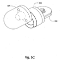
- the method may optionally include attaching or connecting a connecting sleeve, such as, according to one embodiment, a nontransparent connecting sleeve 606 to the front elongated transparent optical unit 604 as shown in Fig. 6C .
- a connecting sleeve such as, according to one embodiment, a nontransparent connecting sleeve 606 to the front elongated transparent optical unit 604 as shown in Fig. 6C .
- the method includes attaching or connecting the electric circuit board to the sleeve 606 as shown in Fig 6D .
- a flexible portion 612 of the electric circuit board 602 is located in a groove (not seen) of the connecting sleeve 606.
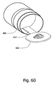
- the method may optionally include inserting one or more batteries, such as batteries 642 into the connecting sleeve 606, as shown in Fig. 6E .
- the method may optionally include, folding the circuit board 602 and attaching a rear optical unit to the connecting sleeve 606.
- a transparent optical rear unit 605 may be attached or connected to the connecting sleeve 606.
- the method of assembling an in vivo imaging device such as device 300 of Fig. 3 , as described above with respect to Fig. 6A , may be carried out in any desired order and is not restricted to the order of the steps as shown in Fig. 6A .
- Fig. 6G is a schematic flow-chart of another method of assembling an in vivo imaging device, such as device 300 of Fig. 3 , in accordance with some embodiments of the invention.
- the method may optionally include the step of providing two optical heads (as mentioned above, an optical head is referred to herein as lens holder 344, 344' along with its associated optical components).
- the method may optionally include the step of attaching the optical heads to the circuit board rigid portions 602.
- the method may optionally include the step of providing the connecting sleeve 606.
- the connecting sleeve 606 is generally cylindrical in form, having two opposing open ends.
- the method may optionally include the step of folding the circuit board so that the optical heads are positioned over the open ends.
- the method may optionally include the step of placing domes 302, 302' (or, equivalently, elongated ends 304, 304' of the device 300) over the optical heads.
- the method may optionally include the step of bringing the domes 302, 302' (or, equivalently, elongated ends 304, 304' of the device 300) into abutment with the connecting sleeve 606 so that the connecting sleeve 606 and the domes 302, 302' form a closed housing.
- the closed housing defines the boundary surface of the in-vivo device 300.
- the method may comprise the optional step of placing at least one battery 345 in a holding sleeve (not shown) prior to being placed in the connecting sleeve 606.
- the holding sleeve may aid in holding a number of batteries together as a single battery pack.
- the holding sleeve may have two opposing open ends.
- step of placing at least one battery 345 in the holding sleeve is performed prior to the step of folding the circuit board so that the optical heads are positioned over the open ends.
- the method may comprise the optional step of placing the at least one battery 345 in placing at least one battery in the connecting sleeve 606.
- the method may comprise placing the connecting sleeve 606 between the two optical heads with the flexible portion 612 passing between the two opposing open ends prior to the step of folding the circuit board; and the at least one battery is placed in the connecting sleeve 606 after positioning one of the optical heads over one of the open ends of the connecting sleeve 606.
- FIG. 7A is a schematic flow-chart of another method of assembling an in vivo imaging device, such as device 300 of Fig. 3 , in accordance with some embodiments of the invention.
- the method may optionally include folding an electric circuit board. For example folding a rigid -flex circuit board around a battery.
- the method may optionally include inserting the rigid-flex circuit board and the battery to a connecting sleeve for example to a nontransparent connecting sleeve.
- the method may optionally include connecting two optical units to the connecting sleeve 606, for example connecting two transparent elongated front and rear optical units 604 and 605, to the nontransparent connecting sleeve 606 as shown in Figs. 7B and 7C .
- the in vivo imaging device components such as the front and rear transparent optical units 604 and 605 and the connecting sleeve 606 may be joined together by using one or more of the following methods: fraction fitting, press fitting, snap fitting, laser welding, laser melting, spin welding, and ultra sonic welding.
Landscapes
- Health & Medical Sciences (AREA)
- Life Sciences & Earth Sciences (AREA)
- Surgery (AREA)
- Engineering & Computer Science (AREA)
- Optics & Photonics (AREA)
- Physics & Mathematics (AREA)
- Medical Informatics (AREA)
- General Health & Medical Sciences (AREA)
- Biophysics (AREA)
- Pathology (AREA)
- Radiology & Medical Imaging (AREA)
- Veterinary Medicine (AREA)
- Biomedical Technology (AREA)
- Heart & Thoracic Surgery (AREA)
- Public Health (AREA)
- Molecular Biology (AREA)
- Animal Behavior & Ethology (AREA)
- Nuclear Medicine, Radiotherapy & Molecular Imaging (AREA)
- Manufacturing & Machinery (AREA)
- Gastroenterology & Hepatology (AREA)
- Microelectronics & Electronic Packaging (AREA)
- Multimedia (AREA)
- Signal Processing (AREA)
- Endoscopes (AREA)
- Measurement Of The Respiration, Hearing Ability, Form, And Blood Characteristics Of Living Organisms (AREA)
- Instruments For Viewing The Inside Of Hollow Bodies (AREA)
- Accessories Of Cameras (AREA)
- Lenses (AREA)
Applications Claiming Priority (1)
| Application Number | Priority Date | Filing Date | Title |
|---|---|---|---|
| US73897205P | 2005-11-23 | 2005-11-23 |
Publications (2)
| Publication Number | Publication Date |
|---|---|
| EP1790280A1 EP1790280A1 (en) | 2007-05-30 |
| EP1790280B1 true EP1790280B1 (en) | 2011-08-03 |
Family
ID=37882277
Family Applications (2)
| Application Number | Title | Priority Date | Filing Date |
|---|---|---|---|
| EP06124509A Active EP1790280B1 (en) | 2005-11-23 | 2006-11-21 | Method of assembling an in-vivo imaging device |
| EP06821566A Active EP1951113B1 (en) | 2005-11-23 | 2006-11-21 | In-vivo imaging device and optical system thereof |
Family Applications After (1)
| Application Number | Title | Priority Date | Filing Date |
|---|---|---|---|
| EP06821566A Active EP1951113B1 (en) | 2005-11-23 | 2006-11-21 | In-vivo imaging device and optical system thereof |
Country Status (6)
| Country | Link |
|---|---|
| US (2) | US7896805B2 (enExample) |
| EP (2) | EP1790280B1 (enExample) |
| JP (2) | JP5203958B2 (enExample) |
| AT (1) | ATE518473T1 (enExample) |
| IL (1) | IL179468A0 (enExample) |
| WO (1) | WO2007060659A2 (enExample) |
Families Citing this family (75)
| Publication number | Priority date | Publication date | Assignee | Title |
|---|---|---|---|---|
| JP4256256B2 (ja) * | 2001-06-18 | 2009-04-22 | ギブン イメージング リミテッド | 硬質の区域および軟質の区域を有する回路基板を備えた生体内センシング装置 |
| US7474327B2 (en) | 2002-02-12 | 2009-01-06 | Given Imaging Ltd. | System and method for displaying an image stream |
| JP2007167125A (ja) * | 2005-12-19 | 2007-07-05 | Olympus Medical Systems Corp | カプセル内視鏡及びその製造方法 |
| CN101404922B (zh) * | 2006-04-25 | 2011-02-02 | 奥林巴斯医疗株式会社 | 胶囊型内窥镜 |
| AU2007322906B2 (en) * | 2006-11-24 | 2011-01-20 | Olympus Medical Systems Corp. | Encapsulated endoscope |
| JP2008142410A (ja) * | 2006-12-12 | 2008-06-26 | Olympus Corp | 被検体内導入装置 |
| JP5074146B2 (ja) * | 2007-03-30 | 2012-11-14 | オリンパス株式会社 | カプセル型医療装置 |
| JP5340566B2 (ja) * | 2007-07-24 | 2013-11-13 | オリンパスメディカルシステムズ株式会社 | 受信装置 |
| JP2009061097A (ja) * | 2007-09-06 | 2009-03-26 | Olympus Medical Systems Corp | カプセル内視鏡 |
| JP2009240634A (ja) * | 2008-03-31 | 2009-10-22 | Olympus Corp | 内視鏡装置 |
| US8636653B2 (en) | 2008-06-09 | 2014-01-28 | Capso Vision, Inc. | In vivo camera with multiple sources to illuminate tissue at different distances |
| US8235888B2 (en) * | 2008-07-08 | 2012-08-07 | Olympus Medical Systems Corp. | System for guiding capsule medical device |
| JP5185008B2 (ja) * | 2008-07-31 | 2013-04-17 | オリンパスメディカルシステムズ株式会社 | カプセル型医療装置 |
| JP5269532B2 (ja) * | 2008-09-22 | 2013-08-21 | オリンパスメディカルシステムズ株式会社 | カプセル型医療装置 |
| US20100130837A1 (en) * | 2008-11-25 | 2010-05-27 | The Smart Pill Corporation | Modular ingestible capsule |
| EP2356932A4 (en) * | 2008-12-09 | 2012-07-04 | Olympus Medical Systems Corp | ENCAPSULATED MEDICAL DEVICE AND MANUFACTURING METHOD THEREFOR |
| US9113845B2 (en) * | 2009-01-08 | 2015-08-25 | Given Imaging Ltd. | Device and method for assembling in vivo sensing devices |
| AU2010209278B2 (en) | 2009-01-29 | 2014-10-23 | Given Imaging Ltd. | Device,system and method for detection of bleeding |
| US9402533B2 (en) | 2011-03-07 | 2016-08-02 | Endochoice Innovation Center Ltd. | Endoscope circuit board assembly |
| US11547275B2 (en) | 2009-06-18 | 2023-01-10 | Endochoice, Inc. | Compact multi-viewing element endoscope system |
| CA2765559C (en) | 2009-06-18 | 2017-09-05 | Peer Medical Ltd. | Multi-camera endoscope |
| US11864734B2 (en) | 2009-06-18 | 2024-01-09 | Endochoice, Inc. | Multi-camera endoscope |
| US8926502B2 (en) | 2011-03-07 | 2015-01-06 | Endochoice, Inc. | Multi camera endoscope having a side service channel |
| US9872609B2 (en) | 2009-06-18 | 2018-01-23 | Endochoice Innovation Center Ltd. | Multi-camera endoscope |
| US9901244B2 (en) | 2009-06-18 | 2018-02-27 | Endochoice, Inc. | Circuit board assembly of a multiple viewing elements endoscope |
| US12137873B2 (en) | 2009-06-18 | 2024-11-12 | Endochoice, Inc. | Compact multi-viewing element endoscope system |
| US9101287B2 (en) | 2011-03-07 | 2015-08-11 | Endochoice Innovation Center Ltd. | Multi camera endoscope assembly having multiple working channels |
| US9706903B2 (en) | 2009-06-18 | 2017-07-18 | Endochoice, Inc. | Multiple viewing elements endoscope system with modular imaging units |
| US9713417B2 (en) | 2009-06-18 | 2017-07-25 | Endochoice, Inc. | Image capture assembly for use in a multi-viewing elements endoscope |
| US9101268B2 (en) | 2009-06-18 | 2015-08-11 | Endochoice Innovation Center Ltd. | Multi-camera endoscope |
| US9492063B2 (en) | 2009-06-18 | 2016-11-15 | Endochoice Innovation Center Ltd. | Multi-viewing element endoscope |
| US11278190B2 (en) | 2009-06-18 | 2022-03-22 | Endochoice, Inc. | Multi-viewing element endoscope |
| US9642513B2 (en) | 2009-06-18 | 2017-05-09 | Endochoice Inc. | Compact multi-viewing element endoscope system |
| US10165929B2 (en) | 2009-06-18 | 2019-01-01 | Endochoice, Inc. | Compact multi-viewing element endoscope system |
| US8516691B2 (en) | 2009-06-24 | 2013-08-27 | Given Imaging Ltd. | Method of assembly of an in vivo imaging device with a flexible circuit board |
| US9237839B2 (en) | 2009-12-17 | 2016-01-19 | Given Imaging Ltd. | Device, system and method for activation, calibration and testing of an in-vivo imaging device |
| US8682142B1 (en) | 2010-03-18 | 2014-03-25 | Given Imaging Ltd. | System and method for editing an image stream captured in-vivo |
| US12220105B2 (en) | 2010-06-16 | 2025-02-11 | Endochoice, Inc. | Circuit board assembly of a multiple viewing elements endoscope |
| US10080486B2 (en) | 2010-09-20 | 2018-09-25 | Endochoice Innovation Center Ltd. | Multi-camera endoscope having fluid channels |
| US9560953B2 (en) | 2010-09-20 | 2017-02-07 | Endochoice, Inc. | Operational interface in a multi-viewing element endoscope |
| EP3540495A1 (en) | 2010-10-28 | 2019-09-18 | EndoChoice Innovation Center Ltd. | Optical systems for multi-sensor endoscopes |
| US12204087B2 (en) | 2010-10-28 | 2025-01-21 | Endochoice, Inc. | Optical systems for multi-sensor endoscopes |
| WO2012073634A1 (ja) * | 2010-11-29 | 2012-06-07 | オリンパスメディカルシステムズ株式会社 | カプセル型医療装置及びその製造方法 |
| CN107361721B (zh) | 2010-12-09 | 2019-06-18 | 恩多巧爱思创新中心有限公司 | 用于多摄像头内窥镜的柔性电子电路板 |
| US11889986B2 (en) | 2010-12-09 | 2024-02-06 | Endochoice, Inc. | Flexible electronic circuit board for a multi-camera endoscope |
| EP3420886B8 (en) | 2010-12-09 | 2020-07-15 | EndoChoice, Inc. | Flexible electronic circuit board multi-camera endoscope |
| US9101266B2 (en) | 2011-02-07 | 2015-08-11 | Endochoice Innovation Center Ltd. | Multi-element cover for a multi-camera endoscope |
| CN103533881A (zh) * | 2011-03-17 | 2014-01-22 | 基文影像公司 | 可再用的体内装置、系统及其组装方法 |
| DE102011007190A1 (de) * | 2011-04-12 | 2012-10-18 | Henke-Sass, Wolf Gmbh | Endoskop |
| JP5806557B2 (ja) * | 2011-08-31 | 2015-11-10 | オリンパス株式会社 | カプセル型内視鏡 |
| JP5913870B2 (ja) * | 2011-08-31 | 2016-04-27 | オリンパス株式会社 | カプセル型医療装置 |
| JP2012086029A (ja) * | 2011-12-01 | 2012-05-10 | Olympus Medical Systems Corp | カプセル内視鏡 |
| EP2604175B1 (en) | 2011-12-13 | 2019-11-20 | EndoChoice Innovation Center Ltd. | Removable tip endoscope |
| EP2604172B1 (en) | 2011-12-13 | 2015-08-12 | EndoChoice Innovation Center Ltd. | Rotatable connector for an endoscope |
| EP2810216B1 (en) | 2012-01-31 | 2017-11-15 | Given Imaging Ltd. | System and method for displaying motility events in an in vivo image stream |
| EP2859831A4 (en) * | 2012-06-08 | 2016-06-29 | Olympus Corp | CAPSULE TYPE ENDOSCOPE DEVICE, RECEPTION DEVICE, AND CAPSULE TYPE ENDOSCOPE SYSTEM |
| EP2868100B1 (en) | 2012-06-29 | 2019-01-30 | Given Imaging Ltd. | System and method for displaying an image stream |
| US9560954B2 (en) | 2012-07-24 | 2017-02-07 | Endochoice, Inc. | Connector for use with endoscope |
| US10045713B2 (en) | 2012-08-16 | 2018-08-14 | Rock West Medical Devices, Llc | System and methods for triggering a radiofrequency transceiver in the human body |
| US9986899B2 (en) | 2013-03-28 | 2018-06-05 | Endochoice, Inc. | Manifold for a multiple viewing elements endoscope |
| US9993142B2 (en) | 2013-03-28 | 2018-06-12 | Endochoice, Inc. | Fluid distribution device for a multiple viewing elements endoscope |
| US10499794B2 (en) | 2013-05-09 | 2019-12-10 | Endochoice, Inc. | Operational interface in a multi-viewing element endoscope |
| US9430706B1 (en) | 2013-10-02 | 2016-08-30 | Given Imaging Ltd. | System and method for detection of in-vivo pathology sequences |
| JP6767261B2 (ja) | 2013-10-22 | 2020-10-14 | ロック ウエスト メディカル デバイス, エルエルシー | 3つの送信要素を有する飲み込み可能な錠剤センサーの位置を特定するシステム |
| WO2015170319A2 (en) | 2014-05-09 | 2015-11-12 | Given Imaging Ltd. | System and method for sequential image analysis of an in vivo image stream |
| CN107847108B (zh) * | 2015-07-10 | 2019-10-29 | 夏普株式会社 | 体内拍摄装置、体内监视相机系统 |
| CN108289597A (zh) * | 2015-10-27 | 2018-07-17 | 奥林巴斯株式会社 | 摄像装置以及内窥镜 |
| CN110381805B (zh) * | 2017-03-16 | 2022-10-11 | 基文影像公司 | 用于体内装置的位置检测的系统和方法 |
| GB2574417B (en) * | 2018-06-05 | 2021-03-03 | Dyson Technology Ltd | A vision system for a mobile robot |
| CN108633179A (zh) * | 2018-06-12 | 2018-10-09 | 绿烟实业(深圳)有限公司 | 烟具内部连接电路板和采用该电路板的烟具 |
| USD1060669S1 (en) | 2019-04-09 | 2025-02-04 | AnX Robotica Corp | Tether for a capsule endoscope |
| JP7565297B2 (ja) * | 2019-04-09 | 2024-10-10 | アンクス ロボティカ コーポレーション | 液体生検用物質および薬物を送達するためのシステムとその方法 |
| CN111012291A (zh) * | 2019-12-23 | 2020-04-17 | 重庆金山医疗技术研究院有限公司 | 胶囊内镜pcb板固定支架、固定方法及内镜胶囊 |
| CN111808916A (zh) | 2020-07-24 | 2020-10-23 | 上海安翰医疗技术有限公司 | 胰蛋白酶检测薄膜及其制备方法、应用和胰蛋白酶检测试剂盒 |
| CN113382591A (zh) * | 2021-06-07 | 2021-09-10 | 深圳市资福医疗技术有限公司 | Pcb板固定结构、胶囊内窥镜及胶囊内窥镜组装方法 |
Family Cites Families (121)
| Publication number | Priority date | Publication date | Assignee | Title |
|---|---|---|---|---|
| US78134A (en) * | 1868-05-19 | Assig-nob to himself | ||
| US298387A (en) | 1884-05-13 | jewell | ||
| US3509270A (en) * | 1968-04-08 | 1970-04-28 | Ney Co J M | Interconnection for printed circuits and method of making same |
| US3683890A (en) * | 1970-10-02 | 1972-08-15 | Charles B Beal | Carrier system for delivery of an end of an elongated member to the upper gastrointestinal tract |
| US3683389A (en) * | 1971-01-20 | 1972-08-08 | Corning Glass Works | Omnidirectional loop antenna array |
| US3791377A (en) * | 1971-06-30 | 1974-02-12 | T Norby | Radio capsule battery |
| US3971362A (en) * | 1972-10-27 | 1976-07-27 | The United States Of America As Represented By The Administrator Of The National Aeronautics And Space Administration | Miniature ingestible telemeter devices to measure deep-body temperature |
| US4262632A (en) * | 1974-01-03 | 1981-04-21 | Hanton John P | Electronic livestock identification system |
| JPS51141666A (en) * | 1975-06-02 | 1976-12-06 | Seiko Epson Corp | Solar cell wrist watch |
| US4319563A (en) * | 1977-12-02 | 1982-03-16 | Olympus Optical Co., Ltd. | Endoscope with a smoothly curved distal end face |
| JPS5519124A (en) * | 1978-07-27 | 1980-02-09 | Olympus Optical Co | Camera system for medical treatment |
| US5993378A (en) * | 1980-10-28 | 1999-11-30 | Lemelson; Jerome H. | Electro-optical instruments and methods for treating disease |
| US4803992A (en) * | 1980-10-28 | 1989-02-14 | Lemelson Jerome H | Electro-optical instruments and methods for producing same |
| JPS57156736A (en) * | 1981-03-23 | 1982-09-28 | Olympus Optical Co | Therapeutic capsule apparatus |
| JPH0312000Y2 (enExample) * | 1981-04-20 | 1991-03-22 | ||
| DE3337455A1 (de) * | 1982-10-15 | 1984-04-19 | Olympus Optical Co., Ltd., Tokio/Tokyo | Endoskopisches photografiegeraet |
| DE3440177A1 (de) | 1984-11-02 | 1986-05-15 | Friedrich Dipl.-Ing. 8031 Eichenau Hilliges | Fernseh-aufnahme- und -wiedergabeeinrichtung zur endoskopie an menschlichen und tierischen koerpern |
| US5318024A (en) * | 1985-03-22 | 1994-06-07 | Massachusetts Institute Of Technology | Laser endoscope for spectroscopic imaging |
| US4742817A (en) * | 1985-05-15 | 1988-05-10 | Olympus Optical Co., Ltd. | Endoscopic apparatus having a bendable insertion section |
| US4689621A (en) * | 1986-03-31 | 1987-08-25 | The United States Of America As Represented By The Administrator Of The National Aeronautics And Space Administration | Temperature responsive transmitter |
| JPH0664243B2 (ja) * | 1986-04-30 | 1994-08-22 | オリンパス光学工業株式会社 | 内視鏡 |
| JPS6349125A (ja) * | 1986-08-16 | 1988-03-01 | 奥津 一郎 | 内視鏡用案内管 |
| US4742183A (en) * | 1986-10-24 | 1988-05-03 | Napco Security Systems, Inc. | Methods and techniques for fabricating foldable printed circuit boards |
| US4939792A (en) * | 1987-11-16 | 1990-07-03 | Motorola, Inc. | Moldable/foldable radio housing |
| US4860732A (en) * | 1987-11-25 | 1989-08-29 | Olympus Optical Co., Ltd. | Endoscope apparatus provided with endoscope insertion aid |
| US5021888A (en) * | 1987-12-18 | 1991-06-04 | Kabushiki Kaisha Toshiba | Miniaturized solid state imaging device |
| US4936823A (en) * | 1988-05-04 | 1990-06-26 | Triangle Research And Development Corp. | Transendoscopic implant capsule |
| US4844076A (en) * | 1988-08-26 | 1989-07-04 | The Johns Hopkins University | Ingestible size continuously transmitting temperature monitoring pill |
| DE3836349A1 (de) * | 1988-10-25 | 1990-05-03 | Forschungsgesellschaft Fuer Bi | Katheter zur messung von motilitaet und peristaltik in schlauchfoermigen, ihren inhalt transportierenden organen mittels simultaner multipler impedanzmessung |
| US5025704A (en) * | 1989-04-14 | 1991-06-25 | Airjack Wireless Systems Incorporated | Cordless guitar transmitter |
| US4940997A (en) * | 1989-08-08 | 1990-07-10 | Hewlett-Packard Company | Out-of-ink sensing method |
| EP0419729A1 (de) * | 1989-09-29 | 1991-04-03 | Siemens Aktiengesellschaft | Ortung eines Katheters mittels nichtionisierender Felder |
| US5081041A (en) * | 1990-04-03 | 1992-01-14 | Minnesota Mining And Manufacturing Company | Ionic component sensor and method for making and using same |
| GB9018660D0 (en) * | 1990-08-24 | 1990-10-10 | Imperial College | Probe system |
| JP3216650B2 (ja) * | 1990-08-27 | 2001-10-09 | オリンパス光学工業株式会社 | 固体撮像装置 |
| JPH04144533A (ja) | 1990-10-05 | 1992-05-19 | Olympus Optical Co Ltd | 内視鏡 |
| JP3164609B2 (ja) * | 1990-10-31 | 2001-05-08 | オリンパス光学工業株式会社 | 内視鏡装置 |
| US5395366A (en) * | 1991-05-30 | 1995-03-07 | The State University Of New York | Sampling capsule and process |
| US5279607A (en) * | 1991-05-30 | 1994-01-18 | The State University Of New York | Telemetry capsule and process |
| US5330427A (en) * | 1991-07-02 | 1994-07-19 | Ortho Pharmaceutical Corporation | Prefilled suppository applicator |
| US5211165A (en) * | 1991-09-03 | 1993-05-18 | General Electric Company | Tracking system to follow the position and orientation of a device with radiofrequency field gradients |
| FR2687336B1 (fr) * | 1992-02-14 | 1996-05-15 | Jammes Ind Sa | Ligne de production automatisee de viroles roulees soudees. |
| US5241170A (en) * | 1992-02-19 | 1993-08-31 | Itt Corporation | Fiber optic imaging device and methods |
| US5913820A (en) * | 1992-08-14 | 1999-06-22 | British Telecommunications Public Limited Company | Position location system |
| US5381784A (en) * | 1992-09-30 | 1995-01-17 | Adair; Edwin L. | Stereoscopic endoscope |
| US5495114A (en) * | 1992-09-30 | 1996-02-27 | Adair; Edwin L. | Miniaturized electronic imaging chip |
| US5398689A (en) * | 1993-06-16 | 1995-03-21 | Hewlett-Packard Company | Ultrasonic probe assembly and cable therefor |
| US5398670A (en) * | 1993-08-31 | 1995-03-21 | Ethicon, Inc. | Lumen traversing device |
| ES2213150T3 (es) * | 1993-10-01 | 2004-08-16 | Target Therapeutics, Inc. | Cateter multipolar y alambre-guia con cubierta para la deteccion de la actividad electrica cardiaca. |
| JP3392920B2 (ja) * | 1993-11-26 | 2003-03-31 | ペンタックス株式会社 | 内視鏡の先端部 |
| US5426263A (en) * | 1993-12-23 | 1995-06-20 | Motorola, Inc. | Electronic assembly having a double-sided leadless component |
| IL108352A (en) * | 1994-01-17 | 2000-02-29 | Given Imaging Ltd | In vivo video camera system |
| JPH0969983A (ja) * | 1995-08-30 | 1997-03-11 | Matsushita Electric Ind Co Ltd | 固体撮像装置 |
| US5734418A (en) * | 1996-07-17 | 1998-03-31 | Welch Allyn, Inc. | Endoscope with tab imager package |
| US5857963A (en) * | 1996-07-17 | 1999-01-12 | Welch Allyn, Inc. | Tab imager assembly for use in an endoscope |
| US5754313A (en) * | 1996-07-17 | 1998-05-19 | Welch Allyn, Inc. | Imager assembly |
| US6225688B1 (en) * | 1997-12-11 | 2001-05-01 | Tessera, Inc. | Stacked microelectronic assembly and method therefor |
| JP4054094B2 (ja) * | 1996-12-27 | 2008-02-27 | オリンパス株式会社 | 電子内視鏡 |
| WO1998029772A1 (en) * | 1996-12-31 | 1998-07-09 | Honeywell Inc. | Flexible optic connector assembly |
| US5908294A (en) * | 1997-06-12 | 1999-06-01 | Schick Technologies, Inc | Dental imaging system with lamps and method |
| US5984875A (en) * | 1997-08-22 | 1999-11-16 | Innotek Pet Products, Inc. | Ingestible animal temperature sensor |
| US5929901A (en) * | 1997-10-06 | 1999-07-27 | Adair; Edwin L. | Reduced area imaging devices incorporated within surgical instruments |
| US6043839A (en) * | 1997-10-06 | 2000-03-28 | Adair; Edwin L. | Reduced area imaging devices |
| US6038079A (en) * | 1997-10-09 | 2000-03-14 | Imagyn Medical Technologies, Inc. | Sapphire objective system |
| US6240312B1 (en) * | 1997-10-23 | 2001-05-29 | Robert R. Alfano | Remote-controllable, micro-scale device for use in in vivo medical diagnosis and/or treatment |
| US6369812B1 (en) * | 1997-11-26 | 2002-04-09 | Philips Medical Systems, (Cleveland), Inc. | Inter-active viewing system for generating virtual endoscopy studies of medical diagnostic data with a continuous sequence of spherical panoramic views and viewing the studies over networks |
| US6174291B1 (en) * | 1998-03-09 | 2001-01-16 | Spectrascience, Inc. | Optical biopsy system and methods for tissue diagnosis |
| US6395562B1 (en) * | 1998-04-22 | 2002-05-28 | The Regents Of The University Of California | Diagnostic microarray apparatus |
| US6142630A (en) * | 1998-05-08 | 2000-11-07 | Koester; Charles J. | Variable focus lens system such as for examination or treatment of transparent or semi-transparent materials such as ocular tissue |
| US6310985B1 (en) * | 1998-07-29 | 2001-10-30 | Electroglas, Inc. | Measuring angular rotation of an object |
| EP0978251B1 (en) * | 1998-08-07 | 2005-01-26 | Olympus Corporation | Endoscope capable of being autoclaved |
| US6228048B1 (en) * | 1998-10-23 | 2001-05-08 | Cm Robbins Company Inc. | Colonic irrigation apparatus and method |
| US7116352B2 (en) * | 1999-02-25 | 2006-10-03 | Visionsense Ltd. | Capsule |
| US8636648B2 (en) * | 1999-03-01 | 2014-01-28 | West View Research, Llc | Endoscopic smart probe |
| US6273904B1 (en) * | 1999-03-02 | 2001-08-14 | Light Sciences Corporation | Polymer battery for internal light device |
| US6088606A (en) * | 1999-03-22 | 2000-07-11 | Spectrx, Inc. | Method and apparatus for determining a duration of a medical condition |
| US6233476B1 (en) * | 1999-05-18 | 2001-05-15 | Mediguide Ltd. | Medical positioning system |
| US20020015952A1 (en) * | 1999-07-30 | 2002-02-07 | Anderson Norman G. | Microarrays and their manufacture by slicing |
| US6400338B1 (en) * | 2000-01-11 | 2002-06-04 | Destron-Fearing Corporation | Passive integrated transponder tag with unitary antenna core |
| US6366186B1 (en) * | 2000-01-20 | 2002-04-02 | Jds Uniphase Inc. | Mems magnetically actuated switches and associated switching arrays |
| US7039453B2 (en) * | 2000-02-08 | 2006-05-02 | Tarun Mullick | Miniature ingestible capsule |
| KR100798048B1 (ko) | 2000-03-08 | 2008-01-24 | 기븐 이미징 리미티드 | 체내 촬상용 캡슐 |
| US6338347B1 (en) * | 2000-04-04 | 2002-01-15 | Yun-Yin Chung | Blood circulation stimulator |
| US6692430B2 (en) * | 2000-04-10 | 2004-02-17 | C2Cure Inc. | Intra vascular imaging apparatus |
| US6709387B1 (en) * | 2000-05-15 | 2004-03-23 | Given Imaging Ltd. | System and method for controlling in vivo camera capture and display rate |
| US6804552B2 (en) * | 2000-11-03 | 2004-10-12 | Medtronic, Inc. | MEMs switching circuit and method for an implantable medical device |
| KR100870033B1 (ko) * | 2001-01-16 | 2008-11-21 | 기븐 이미징 리미티드 | 체강의 광시야 영상화 시스템 및 방법 |
| IL143259A (en) * | 2001-05-20 | 2006-08-01 | Given Imaging Ltd | A method of moving a bone in the colon |
| JP4256256B2 (ja) * | 2001-06-18 | 2009-04-22 | ギブン イメージング リミテッド | 硬質の区域および軟質の区域を有する回路基板を備えた生体内センシング装置 |
| IL159451A0 (en) * | 2001-06-20 | 2004-06-01 | Given Imaging Ltd | Motility analysis within a gastrointestinal tract |
| US20030043263A1 (en) * | 2001-07-26 | 2003-03-06 | Arkady Glukhovsky | Diagnostic device using data compression |
| US20030117491A1 (en) * | 2001-07-26 | 2003-06-26 | Dov Avni | Apparatus and method for controlling illumination in an in-vivo imaging device |
| US6949154B2 (en) * | 2001-07-28 | 2005-09-27 | Boehringer Ingelheim Pharma Kg | Method and apparatus for sealing medicinal capsules |
| JP4744026B2 (ja) | 2001-07-30 | 2011-08-10 | オリンパス株式会社 | カプセル内視鏡およびカプセル内視鏡システム |
| US6951536B2 (en) * | 2001-07-30 | 2005-10-04 | Olympus Corporation | Capsule-type medical device and medical system |
| IL151049A0 (en) * | 2001-08-02 | 2003-04-10 | Given Imaging Ltd | In vivo imaging methods and devices |
| US7877134B2 (en) * | 2001-08-02 | 2011-01-25 | Given Imaging Ltd. | Apparatus and methods for in vivo imaging |
| US6916286B2 (en) * | 2001-08-09 | 2005-07-12 | Smith & Nephew, Inc. | Endoscope with imaging probe |
| CN100354889C (zh) * | 2001-09-05 | 2007-12-12 | 吉温成象有限公司 | 用于体腔的三维显示的系统和方法 |
| JP4796275B2 (ja) * | 2001-09-24 | 2011-10-19 | ギブン イメージング リミテッド | 生体内の装置を制御するためのシステムおよび方法 |
| US8423110B2 (en) * | 2002-01-09 | 2013-04-16 | Boston Scientific Scimed, Inc. | Imaging device and related methods |
| US20030158503A1 (en) * | 2002-01-18 | 2003-08-21 | Shinya Matsumoto | Capsule endoscope and observation system that uses it |
| JP3957271B2 (ja) * | 2002-01-22 | 2007-08-15 | オリンパス株式会社 | カプセル型医療装置 |
| US7474327B2 (en) * | 2002-02-12 | 2009-01-06 | Given Imaging Ltd. | System and method for displaying an image stream |
| US7473218B2 (en) | 2002-08-06 | 2009-01-06 | Olympus Corporation | Assembling method of capsule medical apparatus |
| US20040087832A1 (en) * | 2002-10-30 | 2004-05-06 | Arkady Glukhovsky | Device and method for blocking activation of an in-vivo sensor |
| JP2004275542A (ja) * | 2003-03-17 | 2004-10-07 | Olympus Corp | カプセル型内視鏡 |
| DE10323216B3 (de) | 2003-05-22 | 2004-12-23 | Siemens Ag | Endoskopieeinrichtung |
| US7153259B2 (en) * | 2003-09-01 | 2006-12-26 | Olympus Corporation | Capsule type endoscope |
| JP4128504B2 (ja) * | 2003-09-05 | 2008-07-30 | オリンパス株式会社 | カプセル型内視鏡 |
| JP4128505B2 (ja) * | 2003-09-05 | 2008-07-30 | オリンパス株式会社 | カプセル型内視鏡 |
| JP4767486B2 (ja) * | 2003-10-10 | 2011-09-07 | オリンパス株式会社 | 医療用カプセル |
| JP4009581B2 (ja) * | 2003-11-18 | 2007-11-14 | オリンパス株式会社 | カプセル型医療システム |
| JP3850416B2 (ja) * | 2004-03-16 | 2006-11-29 | オリンパス株式会社 | 医療用カプセル筐体とその製造方法 |
| EP1702555B1 (en) * | 2004-01-07 | 2016-12-07 | Olympus Corporation | Capsule type medical device, medical capsule enclosure and production method therefor |
| JP4533635B2 (ja) * | 2004-01-21 | 2010-09-01 | オリンパス株式会社 | カプセル型医療装置の製造方法 |
| JP2005205071A (ja) * | 2004-01-26 | 2005-08-04 | Olympus Corp | カプセル型医療装置 |
| JP4472401B2 (ja) * | 2004-03-29 | 2010-06-02 | オリンパス株式会社 | 被検体内情報取得装置 |
| US8500630B2 (en) | 2004-06-30 | 2013-08-06 | Given Imaging Ltd. | In vivo device with flexible circuit board and method for assembly thereof |
| JP4589048B2 (ja) * | 2004-08-04 | 2010-12-01 | オリンパス株式会社 | カプセル型内視鏡 |
| TWI271549B (en) * | 2004-10-14 | 2007-01-21 | Nanophotonics Ltd | Rectilinear mirror and imaging system having the same |
-
2006
- 2006-11-20 US US11/601,831 patent/US7896805B2/en active Active
- 2006-11-21 EP EP06124509A patent/EP1790280B1/en active Active
- 2006-11-21 WO PCT/IL2006/001342 patent/WO2007060659A2/en not_active Ceased
- 2006-11-21 JP JP2008541910A patent/JP5203958B2/ja active Active
- 2006-11-21 IL IL179468A patent/IL179468A0/en active IP Right Grant
- 2006-11-21 EP EP06821566A patent/EP1951113B1/en active Active
- 2006-11-21 AT AT06124509T patent/ATE518473T1/de not_active IP Right Cessation
- 2006-11-22 US US11/603,123 patent/US20070118012A1/en not_active Abandoned
- 2006-11-24 JP JP2006317312A patent/JP5016903B2/ja not_active Expired - Fee Related
Also Published As
| Publication number | Publication date |
|---|---|
| JP5016903B2 (ja) | 2012-09-05 |
| US7896805B2 (en) | 2011-03-01 |
| IL179468A0 (en) | 2007-05-15 |
| EP1951113A4 (en) | 2010-01-13 |
| EP1790280A1 (en) | 2007-05-30 |
| US20070118012A1 (en) | 2007-05-24 |
| US20070118018A1 (en) | 2007-05-24 |
| WO2007060659A2 (en) | 2007-05-31 |
| JP5203958B2 (ja) | 2013-06-05 |
| EP1951113A2 (en) | 2008-08-06 |
| JP2009519732A (ja) | 2009-05-21 |
| EP1951113B1 (en) | 2012-08-08 |
| ATE518473T1 (de) | 2011-08-15 |
| WO2007060659A3 (en) | 2009-09-03 |
| JP2007144182A (ja) | 2007-06-14 |
Similar Documents
| Publication | Publication Date | Title |
|---|---|---|
| EP1790280B1 (en) | Method of assembling an in-vivo imaging device | |
| US8063933B2 (en) | Battery contacts for an in-vivo imaging device | |
| US8516691B2 (en) | Method of assembly of an in vivo imaging device with a flexible circuit board | |
| US7662093B2 (en) | Reduced size imaging device | |
| CN100508872C (zh) | 被检体内导入装置 | |
| EP1709899B1 (en) | Capsule-type endoscope | |
| JP4515747B2 (ja) | カプセル型医療装置 | |
| JP4009473B2 (ja) | カプセル型内視鏡 | |
| CN101160087B (zh) | 被检体内导入装置及被检体内信息获得系统 | |
| WO2007074430A1 (en) | Device, system and method for activation of an in vivo device | |
| WO2008072420A1 (ja) | 被検体内導入装置 | |
| US20170164820A1 (en) | Capsule medical device | |
| US8177712B2 (en) | Body insertable apparatus and body-insertable apparatus system | |
| JP2005080713A (ja) | カプセル型内視鏡 | |
| US20070167834A1 (en) | In-vivo imaging optical device and method | |
| US20090281389A1 (en) | Device, system, and method for adaptive imaging | |
| JP4516139B2 (ja) | カプセル型医療装置 | |
| JP2005204802A (ja) | カプセル型医療装置の製造方法 | |
| JP4373180B2 (ja) | カプセル型内視鏡および撮像装置 | |
| JP4488286B2 (ja) | カプセル型医療装置 | |
| KR101245292B1 (ko) | 생체 내 정보 센싱장치 및 그 조립방법 | |
| JP4515100B2 (ja) | 内視鏡用撮像装置 | |
| JP2006187456A (ja) | カプセル内視鏡 |
Legal Events
| Date | Code | Title | Description |
|---|---|---|---|
| PUAI | Public reference made under article 153(3) epc to a published international application that has entered the european phase |
Free format text: ORIGINAL CODE: 0009012 |
|
| AK | Designated contracting states |
Kind code of ref document: A1 Designated state(s): AT BE BG CH CY CZ DE DK EE ES FI FR GB GR HU IE IS IT LI LT LU LV MC NL PL PT RO SE SI SK TR |
|
| AX | Request for extension of the european patent |
Extension state: AL BA HR MK YU |
|
| 17P | Request for examination filed |
Effective date: 20070725 |
|
| 17Q | First examination report despatched |
Effective date: 20070904 |
|
| AKX | Designation fees paid |
Designated state(s): AT BE BG CH CY CZ DE DK EE ES FI FR GB GR HU IE IS IT LI LT LU LV MC NL PL PT RO SE SI SK TR |
|
| GRAP | Despatch of communication of intention to grant a patent |
Free format text: ORIGINAL CODE: EPIDOSNIGR1 |
|
| GRAS | Grant fee paid |
Free format text: ORIGINAL CODE: EPIDOSNIGR3 |
|
| GRAA | (expected) grant |
Free format text: ORIGINAL CODE: 0009210 |
|
| AK | Designated contracting states |
Kind code of ref document: B1 Designated state(s): AT BE BG CH CY CZ DE DK EE ES FI FR GB GR HU IE IS IT LI LT LU LV MC NL PL PT RO SE SI SK TR |
|
| REG | Reference to a national code |
Ref country code: GB Ref legal event code: FG4D |
|
| REG | Reference to a national code |
Ref country code: CH Ref legal event code: EP |
|
| REG | Reference to a national code |
Ref country code: IE Ref legal event code: FG4D |
|
| REG | Reference to a national code |
Ref country code: DE Ref legal event code: R096 Ref document number: 602006023470 Country of ref document: DE Effective date: 20110929 |
|
| REG | Reference to a national code |
Ref country code: NL Ref legal event code: VDEP Effective date: 20110803 |
|
| LTIE | Lt: invalidation of european patent or patent extension |
Effective date: 20110803 |
|
| PG25 | Lapsed in a contracting state [announced via postgrant information from national office to epo] |
Ref country code: IS Free format text: LAPSE BECAUSE OF FAILURE TO SUBMIT A TRANSLATION OF THE DESCRIPTION OR TO PAY THE FEE WITHIN THE PRESCRIBED TIME-LIMIT Effective date: 20111203 Ref country code: FI Free format text: LAPSE BECAUSE OF FAILURE TO SUBMIT A TRANSLATION OF THE DESCRIPTION OR TO PAY THE FEE WITHIN THE PRESCRIBED TIME-LIMIT Effective date: 20110803 Ref country code: NL Free format text: LAPSE BECAUSE OF FAILURE TO SUBMIT A TRANSLATION OF THE DESCRIPTION OR TO PAY THE FEE WITHIN THE PRESCRIBED TIME-LIMIT Effective date: 20110803 Ref country code: LT Free format text: LAPSE BECAUSE OF FAILURE TO SUBMIT A TRANSLATION OF THE DESCRIPTION OR TO PAY THE FEE WITHIN THE PRESCRIBED TIME-LIMIT Effective date: 20110803 Ref country code: PT Free format text: LAPSE BECAUSE OF FAILURE TO SUBMIT A TRANSLATION OF THE DESCRIPTION OR TO PAY THE FEE WITHIN THE PRESCRIBED TIME-LIMIT Effective date: 20111205 Ref country code: SE Free format text: LAPSE BECAUSE OF FAILURE TO SUBMIT A TRANSLATION OF THE DESCRIPTION OR TO PAY THE FEE WITHIN THE PRESCRIBED TIME-LIMIT Effective date: 20110803 |
|
| REG | Reference to a national code |
Ref country code: AT Ref legal event code: MK05 Ref document number: 518473 Country of ref document: AT Kind code of ref document: T Effective date: 20110803 |
|
| PG25 | Lapsed in a contracting state [announced via postgrant information from national office to epo] |
Ref country code: PL Free format text: LAPSE BECAUSE OF FAILURE TO SUBMIT A TRANSLATION OF THE DESCRIPTION OR TO PAY THE FEE WITHIN THE PRESCRIBED TIME-LIMIT Effective date: 20110803 Ref country code: AT Free format text: LAPSE BECAUSE OF FAILURE TO SUBMIT A TRANSLATION OF THE DESCRIPTION OR TO PAY THE FEE WITHIN THE PRESCRIBED TIME-LIMIT Effective date: 20110803 Ref country code: GR Free format text: LAPSE BECAUSE OF FAILURE TO SUBMIT A TRANSLATION OF THE DESCRIPTION OR TO PAY THE FEE WITHIN THE PRESCRIBED TIME-LIMIT Effective date: 20111104 Ref country code: CY Free format text: LAPSE BECAUSE OF FAILURE TO SUBMIT A TRANSLATION OF THE DESCRIPTION OR TO PAY THE FEE WITHIN THE PRESCRIBED TIME-LIMIT Effective date: 20110803 Ref country code: SI Free format text: LAPSE BECAUSE OF FAILURE TO SUBMIT A TRANSLATION OF THE DESCRIPTION OR TO PAY THE FEE WITHIN THE PRESCRIBED TIME-LIMIT Effective date: 20110803 Ref country code: LV Free format text: LAPSE BECAUSE OF FAILURE TO SUBMIT A TRANSLATION OF THE DESCRIPTION OR TO PAY THE FEE WITHIN THE PRESCRIBED TIME-LIMIT Effective date: 20110803 |
|
| PG25 | Lapsed in a contracting state [announced via postgrant information from national office to epo] |
Ref country code: BE Free format text: LAPSE BECAUSE OF FAILURE TO SUBMIT A TRANSLATION OF THE DESCRIPTION OR TO PAY THE FEE WITHIN THE PRESCRIBED TIME-LIMIT Effective date: 20110803 |
|
| PG25 | Lapsed in a contracting state [announced via postgrant information from national office to epo] |
Ref country code: SK Free format text: LAPSE BECAUSE OF FAILURE TO SUBMIT A TRANSLATION OF THE DESCRIPTION OR TO PAY THE FEE WITHIN THE PRESCRIBED TIME-LIMIT Effective date: 20110803 Ref country code: CZ Free format text: LAPSE BECAUSE OF FAILURE TO SUBMIT A TRANSLATION OF THE DESCRIPTION OR TO PAY THE FEE WITHIN THE PRESCRIBED TIME-LIMIT Effective date: 20110803 |
|
| PG25 | Lapsed in a contracting state [announced via postgrant information from national office to epo] |
Ref country code: EE Free format text: LAPSE BECAUSE OF FAILURE TO SUBMIT A TRANSLATION OF THE DESCRIPTION OR TO PAY THE FEE WITHIN THE PRESCRIBED TIME-LIMIT Effective date: 20110803 Ref country code: RO Free format text: LAPSE BECAUSE OF FAILURE TO SUBMIT A TRANSLATION OF THE DESCRIPTION OR TO PAY THE FEE WITHIN THE PRESCRIBED TIME-LIMIT Effective date: 20110803 Ref country code: IT Free format text: LAPSE BECAUSE OF FAILURE TO SUBMIT A TRANSLATION OF THE DESCRIPTION OR TO PAY THE FEE WITHIN THE PRESCRIBED TIME-LIMIT Effective date: 20110803 |
|
| PLBE | No opposition filed within time limit |
Free format text: ORIGINAL CODE: 0009261 |
|
| STAA | Information on the status of an ep patent application or granted ep patent |
Free format text: STATUS: NO OPPOSITION FILED WITHIN TIME LIMIT |
|
| PG25 | Lapsed in a contracting state [announced via postgrant information from national office to epo] |
Ref country code: MC Free format text: LAPSE BECAUSE OF NON-PAYMENT OF DUE FEES Effective date: 20111130 Ref country code: DK Free format text: LAPSE BECAUSE OF FAILURE TO SUBMIT A TRANSLATION OF THE DESCRIPTION OR TO PAY THE FEE WITHIN THE PRESCRIBED TIME-LIMIT Effective date: 20110803 |
|
| REG | Reference to a national code |
Ref country code: CH Ref legal event code: PL |
|
| 26N | No opposition filed |
Effective date: 20120504 |
|
| PG25 | Lapsed in a contracting state [announced via postgrant information from national office to epo] |
Ref country code: LI Free format text: LAPSE BECAUSE OF NON-PAYMENT OF DUE FEES Effective date: 20111130 Ref country code: CH Free format text: LAPSE BECAUSE OF NON-PAYMENT OF DUE FEES Effective date: 20111130 |
|
| REG | Reference to a national code |
Ref country code: FR Ref legal event code: ST Effective date: 20120731 |
|
| REG | Reference to a national code |
Ref country code: IE Ref legal event code: MM4A |
|
| REG | Reference to a national code |
Ref country code: DE Ref legal event code: R097 Ref document number: 602006023470 Country of ref document: DE Effective date: 20120504 |
|
| PG25 | Lapsed in a contracting state [announced via postgrant information from national office to epo] |
Ref country code: IE Free format text: LAPSE BECAUSE OF NON-PAYMENT OF DUE FEES Effective date: 20111121 |
|
| PG25 | Lapsed in a contracting state [announced via postgrant information from national office to epo] |
Ref country code: FR Free format text: LAPSE BECAUSE OF NON-PAYMENT OF DUE FEES Effective date: 20111130 |
|
| PG25 | Lapsed in a contracting state [announced via postgrant information from national office to epo] |
Ref country code: ES Free format text: LAPSE BECAUSE OF FAILURE TO SUBMIT A TRANSLATION OF THE DESCRIPTION OR TO PAY THE FEE WITHIN THE PRESCRIBED TIME-LIMIT Effective date: 20111114 |
|
| PG25 | Lapsed in a contracting state [announced via postgrant information from national office to epo] |
Ref country code: LU Free format text: LAPSE BECAUSE OF NON-PAYMENT OF DUE FEES Effective date: 20111121 |
|
| PG25 | Lapsed in a contracting state [announced via postgrant information from national office to epo] |
Ref country code: BG Free format text: LAPSE BECAUSE OF FAILURE TO SUBMIT A TRANSLATION OF THE DESCRIPTION OR TO PAY THE FEE WITHIN THE PRESCRIBED TIME-LIMIT Effective date: 20111103 |
|
| PG25 | Lapsed in a contracting state [announced via postgrant information from national office to epo] |
Ref country code: TR Free format text: LAPSE BECAUSE OF FAILURE TO SUBMIT A TRANSLATION OF THE DESCRIPTION OR TO PAY THE FEE WITHIN THE PRESCRIBED TIME-LIMIT Effective date: 20110803 |
|
| PG25 | Lapsed in a contracting state [announced via postgrant information from national office to epo] |
Ref country code: HU Free format text: LAPSE BECAUSE OF FAILURE TO SUBMIT A TRANSLATION OF THE DESCRIPTION OR TO PAY THE FEE WITHIN THE PRESCRIBED TIME-LIMIT Effective date: 20110803 |
|
| PGFP | Annual fee paid to national office [announced via postgrant information from national office to epo] |
Ref country code: DE Payment date: 20241022 Year of fee payment: 19 |
|
| PGFP | Annual fee paid to national office [announced via postgrant information from national office to epo] |
Ref country code: GB Payment date: 20241022 Year of fee payment: 19 |