EP1786946B1 - Mixtures for evaporation of lithium and lithium dispensers - Google Patents
Mixtures for evaporation of lithium and lithium dispensers Download PDFInfo
- Publication number
- EP1786946B1 EP1786946B1 EP05778885.3A EP05778885A EP1786946B1 EP 1786946 B1 EP1786946 B1 EP 1786946B1 EP 05778885 A EP05778885 A EP 05778885A EP 1786946 B1 EP1786946 B1 EP 1786946B1
- Authority
- EP
- European Patent Office
- Prior art keywords
- lithium
- evaporation
- mixture
- mixture according
- powders
- Prior art date
- Legal status (The legal status is an assumption and is not a legal conclusion. Google has not performed a legal analysis and makes no representation as to the accuracy of the status listed.)
- Expired - Lifetime
Links
Images
Classifications
-
- C—CHEMISTRY; METALLURGY
- C23—COATING METALLIC MATERIAL; COATING MATERIAL WITH METALLIC MATERIAL; CHEMICAL SURFACE TREATMENT; DIFFUSION TREATMENT OF METALLIC MATERIAL; COATING BY VACUUM EVAPORATION, BY SPUTTERING, BY ION IMPLANTATION OR BY CHEMICAL VAPOUR DEPOSITION, IN GENERAL; INHIBITING CORROSION OF METALLIC MATERIAL OR INCRUSTATION IN GENERAL
- C23C—COATING METALLIC MATERIAL; COATING MATERIAL WITH METALLIC MATERIAL; SURFACE TREATMENT OF METALLIC MATERIAL BY DIFFUSION INTO THE SURFACE, BY CHEMICAL CONVERSION OR SUBSTITUTION; COATING BY VACUUM EVAPORATION, BY SPUTTERING, BY ION IMPLANTATION OR BY CHEMICAL VAPOUR DEPOSITION, IN GENERAL
- C23C14/00—Coating by vacuum evaporation, by sputtering or by ion implantation of the coating forming material
- C23C14/06—Coating by vacuum evaporation, by sputtering or by ion implantation of the coating forming material characterised by the coating material
- C23C14/14—Metallic material, boron or silicon
-
- C—CHEMISTRY; METALLURGY
- C23—COATING METALLIC MATERIAL; COATING MATERIAL WITH METALLIC MATERIAL; CHEMICAL SURFACE TREATMENT; DIFFUSION TREATMENT OF METALLIC MATERIAL; COATING BY VACUUM EVAPORATION, BY SPUTTERING, BY ION IMPLANTATION OR BY CHEMICAL VAPOUR DEPOSITION, IN GENERAL; INHIBITING CORROSION OF METALLIC MATERIAL OR INCRUSTATION IN GENERAL
- C23C—COATING METALLIC MATERIAL; COATING MATERIAL WITH METALLIC MATERIAL; SURFACE TREATMENT OF METALLIC MATERIAL BY DIFFUSION INTO THE SURFACE, BY CHEMICAL CONVERSION OR SUBSTITUTION; COATING BY VACUUM EVAPORATION, BY SPUTTERING, BY ION IMPLANTATION OR BY CHEMICAL VAPOUR DEPOSITION, IN GENERAL
- C23C14/00—Coating by vacuum evaporation, by sputtering or by ion implantation of the coating forming material
- C23C14/22—Coating by vacuum evaporation, by sputtering or by ion implantation of the coating forming material characterised by the process of coating
- C23C14/24—Vacuum evaporation
-
- C—CHEMISTRY; METALLURGY
- C23—COATING METALLIC MATERIAL; COATING MATERIAL WITH METALLIC MATERIAL; CHEMICAL SURFACE TREATMENT; DIFFUSION TREATMENT OF METALLIC MATERIAL; COATING BY VACUUM EVAPORATION, BY SPUTTERING, BY ION IMPLANTATION OR BY CHEMICAL VAPOUR DEPOSITION, IN GENERAL; INHIBITING CORROSION OF METALLIC MATERIAL OR INCRUSTATION IN GENERAL
- C23C—COATING METALLIC MATERIAL; COATING MATERIAL WITH METALLIC MATERIAL; SURFACE TREATMENT OF METALLIC MATERIAL BY DIFFUSION INTO THE SURFACE, BY CHEMICAL CONVERSION OR SUBSTITUTION; COATING BY VACUUM EVAPORATION, BY SPUTTERING, BY ION IMPLANTATION OR BY CHEMICAL VAPOUR DEPOSITION, IN GENERAL
- C23C14/00—Coating by vacuum evaporation, by sputtering or by ion implantation of the coating forming material
- C23C14/06—Coating by vacuum evaporation, by sputtering or by ion implantation of the coating forming material characterised by the coating material
- C23C14/14—Metallic material, boron or silicon
- C23C14/18—Metallic material, boron or silicon on other inorganic substrates
-
- C—CHEMISTRY; METALLURGY
- C23—COATING METALLIC MATERIAL; COATING MATERIAL WITH METALLIC MATERIAL; CHEMICAL SURFACE TREATMENT; DIFFUSION TREATMENT OF METALLIC MATERIAL; COATING BY VACUUM EVAPORATION, BY SPUTTERING, BY ION IMPLANTATION OR BY CHEMICAL VAPOUR DEPOSITION, IN GENERAL; INHIBITING CORROSION OF METALLIC MATERIAL OR INCRUSTATION IN GENERAL
- C23C—COATING METALLIC MATERIAL; COATING MATERIAL WITH METALLIC MATERIAL; SURFACE TREATMENT OF METALLIC MATERIAL BY DIFFUSION INTO THE SURFACE, BY CHEMICAL CONVERSION OR SUBSTITUTION; COATING BY VACUUM EVAPORATION, BY SPUTTERING, BY ION IMPLANTATION OR BY CHEMICAL VAPOUR DEPOSITION, IN GENERAL
- C23C14/00—Coating by vacuum evaporation, by sputtering or by ion implantation of the coating forming material
- C23C14/22—Coating by vacuum evaporation, by sputtering or by ion implantation of the coating forming material characterised by the process of coating
- C23C14/24—Vacuum evaporation
- C23C14/243—Crucibles for source material
-
- H—ELECTRICITY
- H10—SEMICONDUCTOR DEVICES; ELECTRIC SOLID-STATE DEVICES NOT OTHERWISE PROVIDED FOR
- H10K—ORGANIC ELECTRIC SOLID-STATE DEVICES
- H10K71/00—Manufacture or treatment specially adapted for the organic devices covered by this subclass
-
- H—ELECTRICITY
- H10—SEMICONDUCTOR DEVICES; ELECTRIC SOLID-STATE DEVICES NOT OTHERWISE PROVIDED FOR
- H10K—ORGANIC ELECTRIC SOLID-STATE DEVICES
- H10K71/00—Manufacture or treatment specially adapted for the organic devices covered by this subclass
- H10K71/30—Doping active layers, e.g. electron transporting layers
-
- H—ELECTRICITY
- H10—SEMICONDUCTOR DEVICES; ELECTRIC SOLID-STATE DEVICES NOT OTHERWISE PROVIDED FOR
- H10K—ORGANIC ELECTRIC SOLID-STATE DEVICES
- H10K71/00—Manufacture or treatment specially adapted for the organic devices covered by this subclass
- H10K71/60—Forming conductive regions or layers, e.g. electrodes
-
- Y—GENERAL TAGGING OF NEW TECHNOLOGICAL DEVELOPMENTS; GENERAL TAGGING OF CROSS-SECTIONAL TECHNOLOGIES SPANNING OVER SEVERAL SECTIONS OF THE IPC; TECHNICAL SUBJECTS COVERED BY FORMER USPC CROSS-REFERENCE ART COLLECTIONS [XRACs] AND DIGESTS
- Y10—TECHNICAL SUBJECTS COVERED BY FORMER USPC
- Y10T—TECHNICAL SUBJECTS COVERED BY FORMER US CLASSIFICATION
- Y10T428/00—Stock material or miscellaneous articles
- Y10T428/12—All metal or with adjacent metals
- Y10T428/12014—All metal or with adjacent metals having metal particles
- Y10T428/12028—Composite; i.e., plural, adjacent, spatially distinct metal components [e.g., layers, etc.]
- Y10T428/12063—Nonparticulate metal component
- Y10T428/12104—Particles discontinuous
- Y10T428/12111—Separated by nonmetal matrix or binder [e.g., welding electrode, etc.]
Definitions
- the present invention relates to mixtures to be employed for lithium evaporation in the industrial applications requiring the same, as well as to lithium dispensers using these mixtures.
- Lithium is employed since long in the electronic field. In particular this metal has been used in the past for the production of photo-sensitive surfaces, such as of image intensifiers or photo-multiplying tubes. Another important use of lithium, in the form of alloys or salts, is in the formation of battery elements.
- an OLED is formed of a first planar transparent support (made of glass or plastics); a second support not necessarily transparent, that can be made in glass, metal or plastics, essentially planar and parallel to the first support and fixed along the perimeter thereof, so as to form a closed space; and an active structure for the image formation in said space.
- the active structure is formed of a first series of transparent, linear and mutually parallel electrodes, generally having anodic functionality, being deposited on the first support; deposited on the first series of electrodes, a multilayer of different electroluminescent organic materials, comprising at least one layer of a material conductor of electrons and one layer of a material conductor of electronic vacancies; a second series of linear and mutually parallel electrodes that are orthogonally oriented with respect to those of the first series and having cathodic functionality, being in contact with the opposite side of the multilayer of organic materials, so that the latter is comprised between the two series of electrodes.
- lithium due to the high reactivity to the atmospheric gases and moisture, lithium (alike any alkali metal) generally is not industrially employed in the form of pure metal, but rather in form of compounds that are stable in air at room temperature. Most generally used compounds are the dichromate, Li 2 Cr 2 O 7 , or more commonly the chromate Li 2 CrO 4 , in admixture with a reducing agent. By heating these mixtures at temperatures generally higher than 500 °C a reaction takes place by which chromium is reduced to a lower valence with the consequence of liberating lithium as a vapor. As reducing agents aluminum, silicon or getter alloys, i.e. titanium- or zirconium-based alloys with aluminum or one or more transition elements, are generally used.
- chromates and dichromates of alkali metals have the disadvantage of containing hexavalent chromium which can cause irritation by contact, swallowing or inhalation and can be carcinogenic in case of long exposures.
- Object of the present invention is to provide mixtures for lithium evaporation which overcome the problems of the prior art.
- lithium salt is chosen among the titanate (Li 2 TiO 3 ), tantalate (LiTaO 3 ), niobate (LiNbO 3 ), tungstate (Li 2 WO 4 ) and zirconate (Li 2 ZrO 3 ).
- mixtures of one reducing agent with a lithium salt chosen among the above-mentioned ones not only eliminates the necessity of making recourse to compounds of hexavalent chromium, but have also additional properties that render advantageous their industrial utilization.
- the features (in particular the speed) of lithium evaporation can be easily controlled and reproduced.
- the mentioned lithium salts are much less hygroscopic than the chromium salts, thus reducing the risk that during the lithium evaporation also moisture may evaporate, which is extremely dangerous for the OLED's functioning.
- the preferred one is the titanate because it is the one showing the highest percentage content of lithium by weight and also because in the tests carried out by the inventors it has been found that this salt is the one requiring the slightest energy quantity for its evaporation; besides, it has been observed that lithium titanate gives rise to a particularly smooth lithium evaporation, that is thus easily controllable.
- the reducing agent employed in the mixtures of the invention can be one of the already known components that are employed in the dispensers based on chromates, such as aluminum, silicon, zirconium or titanium, or alloys containing zirconium or titanium, such as the alloy of percent composition by weight Zr 84% - Al 16%, manufactured and sold by the applicant under the name St 101 ® , or the alloy having the weight composition Zr 76.5% - Fe 23.5%, manufactured and sold by the applicant with the name St 198 ® . It is also possible to use a mixture of a plurality of reducing agents.
- both the mixture components have generally particle size of less than 1 mm and preferably lower than 500 ⁇ m; still more preferably the particle size is comprised between about 10 and 125 ⁇ m. Powders with particles having a size of less than 10 ⁇ m are generally difficult to be treated in manufacturing and to be kept inside the dispenser; furthermore, in case of the reducing agent, excessively fine powders can become pyrophoric giving rise to safety problems in the manufacturing plant. On the contrary, with powders with particle size greater than those indicated the contact between the two components of the mixtures becomes worse and the reaction leading to lithium evaporation results to slow down.
- the weight ratio between the lithium salt and the reducing agent can vary within wide limits. Preferably such a ratio is comprised between 10:1 1 and 1:10.
- the use of the lithium salt in great excess with respect to the reducing agent offers no practical advantage; vice versa, especially when the reducing agent is a getter alloy such as the cited St 101 ® alloy, an excess thereof in the mixture can be useful because the portion not involved in the reaction with the lithium salt can have the effect of sorbing the gases that may be liberated during the reaction.
- a preferred weight ratio between the lithium salt and the reducing agent is 1:5.
- the mixture of the present invention can be used in the form of loose powders. Preferably, however, it is used in the form of pellets, having the advantage of further improving the contact between the mixture components and facilitating the operations of loading the container.
- Another advantage of pellets as compared to powders, that has been observed by the inventors, is that pellets require a lesser amount of energy for lithium evaporation, and lithium load of the mixture is used more thoroughly, as described in greater detail by a test in the examples section.
- the container can be made in any material and shape compatible with the application.
- Materials having these features are for example metals or metallic alloys, a few ceramics or graphite. Employing metals and alloys is preferred due to their easier workability and formability. Another advantage in the use of metals and alloys is that the dispenser can be heated at the temperature of lithium evaporation simply by flowing current through the container walls.
- Preferred metals and alloys for making the container are molybdenum, tantalum, tungsten, nickel, steel and nickel-chromium or nickel-chromium-iron alloys.
- the shape of the container can be any whatsoever among those known from patents US 3,578,834 , US 3,579,459 , US 3,598,384 , US 3,636,302 , US 3,663,121 , US 4,233,936 and US 6,753,648 B2 .
- Containers of various shapes and materials are also available in the trade, for instance by the Austrian company Plansee or the US company Midwest Tungsten Service.
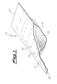
- a first possible shape of dispenser containing a mixture of the invention is shown in figure 1 .
- the dispenser 10 consists of a container with a mixture of the invention inside.
- the container is formed by the assembly of an upper part 11 and a lower part 12; the two parts are preferably made of metal, and joined to each other e.g. by spot-welding.
- the lower part shows in its central zone a recess (obtained e.g. by cold stamping), having housed therein a mixture of the invention, while the upper part has a number of openings 13, 13', ..., to allow the emission of lithium vapors; in the drawing the area of part 11 defined by dashed lines corresponds to the recess in part 12.
- the mixture of the invention can be present in the recess of part 12 in powder form as shown in the drawing, wherein the mixtures is illustrated as element 14; in alternative it is possible to form pellets of mixture and fill therewith the recess.
- Dispenser 10 has at its two ends "wings" 15 and 15', which are particularly adapted for the connection with electrical terminals for heating the dispenser by direct current flow.
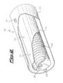
- FIG. 2 Another possible shape of dispenser is shown in figure 2 .
- This container is the object of, and is described in greater detail in, Italian patent application No. MI2004A002279 .
- the dispenser, 20, is formed of a central container 21 and a shield 22.
- Container 21 is closed apart from openings 23; in the drawing it is represented the case that the container has three openings, one of which is hidden by the shield, but these could be present in any number.
- Shield 22 is concentrically arranged around container 21, and kept in the correct position by spacers 24 (only one shown); the shield has openings 25 at positions radially corresponding to openings 23.
- the mixture of the invention between a lithium salt and a reducing agent; the mixture is represented in this case as a plurality of pellets 26, laid in the bottom of the container one aside another. Evaporation of lithium is caused by heating the container, for instance by feeding current to the ends thereof through contacts 27 (only one shown).
- a container like the one shown in figure 1 is manufactured by employing sheets of Inconel (an alloy mainly comprising nickel-chromium, plus minor amounts of other metals) having a thickness of 0.2 mm.
- the container has lateral dimensions of 100 x 24 mm, with a recess 6 mm high being filled up with about 10 g of a mixture between the cited alloy St 101 and Li 2 TiO 3 in a weight ratio of 5:1; the mixture is employed in the form of pellets having diameter of 6 mm and height of 3 mm, being obtained by compression of the powders mixture under a pressure of about 1700 Kg.
- the dispenser is placed on the bottom of an evacuated chamber; a small glass plate, of lateral dimensions 3 x 3 cm is placed above the dispenser at a distance of about 20 cm.
- a direct current 100 A during about six hours; the current flow heats the dispenser up to a temperature of about 800 °C, thus causing the reaction between the mixture components and lithium evaporation; a fraction of the evaporated lithium condenses on the glass plate forming a thin film thereon.
- the chamber is connected to a sample line of a mass spectrometer for monitoring the quantities of emitted gases during the evaporation (obviously except for lithium; due to condensation onto the cold walls of the chamber, this element is not sent to the MS measurement); no substantial gas emissions are observed during the whole test.
- the quantity of evaporated lithium is estimated by measuring the weight difference of the dispenser before and after the test; by taking into account the results of the in-line MS measurement, the weight difference is completely ascribed to the lithium evaporation, thus resulting in a metal evaporation of 100%.
- An analysis of the film formed on the glass plate is also carried out to check its purity, by dissolving it in a HCl solution and chemically analyzing the thus obtained solution through atomic absorption; the film contains a quantity of impurities lower than 1% by weight.
- a quartz crystal monitor (QCM), a device well known in the field to measure the growing speed of thin films by exploiting the variation of the quartz crystal vibration frequency in function of the weight of material deposited thereon; from the knowledge of density and acoustic impedance of metallic lithium, the weight increase is referred to the increase of film thickness with time, thus obtaining a constant speed of film deposition with a value of about 0.2 ⁇ ngstrom per second ( ⁇ /s).
- a lithium dispenser like the one shown in figure 2 , comprising a cylindrical central container and a shield both made of stainless steel of thickness 0.2 mm.
- the container is 10 cm long and has a diameter of 3.1 cm, with two holes of diameter 2.5 mm spaced apart 5 cm along a line on its upper part; the shield, concentrically arranged around the container, is as long as this latter and has a diameter of 3.4 cm, with four holes of diameter 11 mm, two holes facing the holes in the container surface, and the other two ones placed between the first two ones and spaced apart 12 mn from each other.
- the container is filled with 110 g of a mixture between the cited alloy St 101 and Li 2 TiO 3 in a weight ratio of 1:1; the mixture is employed in the form of loose powders.
- the dispenser is placed on the bottom of an evacuated chamber and heated by feeding direct current to the ends of the central container, thus causing lithium evaporation; the test lasts about 40 hours.
- a QCM at a distance of 36 cm from the dispenser to measure the speed of growth of a lithium film, that's proportional to the rate of evaporation of the same metal from the dispenser.
- the QCM is connected via a feed-back loop to the power source, and the system is regulated to obtain a growth speed of 0.28 ⁇ /s.
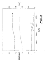
- curve 1 represents the trend of film deposition rate (FDR, measured in ⁇ /s, on the left-hand axis of the graph) as a function of the thickness of lithium film deposited (T, measured in ⁇ );
- curve 2 represents the trend of the voltage measured at the ends of the dispenser during the test (Volts, V, right-hand axis of the graph).
- example 2 The test of example 2 is repeated, with the only difference that in this case the lithium dispensing mixture is present in the form of x pellets having diameter of 6 mm and height of 3 mm, each one of weight about 0.3 g, obtained by compression of the powders mixture under a pressure of about 1700 Kg.
- curve 3 represents the trend of evaporation rate
- curve 4 represents the trend of the voltage measured at the ends of the dispenser during the test.
- Curve 2 is essentially superimposed to curve 1 all along the test, apart from the end tail where a difference in the behavior of dispensers charged with powders or pellets is observed.
- the mixtures of the invention are suitable for the use in industrial processes, as they show constant features of metal evaporation without sudden phenomena, do not give rise to substantial emissions of potentially harmful gases (such as e.g. water), and allow to grow lithium thin films of high purity in a reproducible way and with a constant speed.
- the comparison of results obtained in examples 2 and 3 shows that, while both powders and pellets are suitable for the purposes of the invention, dispensers charged with pellets may be preferable as these allow to evaporate lithium for a longer time with constant evaporation rate (up to a film thickness of about 25800 ⁇ , curve 3 in fig. 3 , vs. a thickness of about 22350 ⁇ obtained with powders, curve 1 in fig.
Landscapes
- Chemical & Material Sciences (AREA)
- Chemical Kinetics & Catalysis (AREA)
- Engineering & Computer Science (AREA)
- Materials Engineering (AREA)
- Mechanical Engineering (AREA)
- Metallurgy (AREA)
- Organic Chemistry (AREA)
- Inorganic Chemistry (AREA)
- Battery Electrode And Active Subsutance (AREA)
- Physical Vapour Deposition (AREA)
- Electroluminescent Light Sources (AREA)
Applications Claiming Priority (2)
| Application Number | Priority Date | Filing Date | Title |
|---|---|---|---|
| IT001736A ITMI20041736A1 (it) | 2004-09-10 | 2004-09-10 | Miscele per l'evaporazione del litio e dispensatori di litio |
| PCT/IT2005/000509 WO2006027814A2 (en) | 2004-09-10 | 2005-09-06 | Mixtures for evaporation of lithium and lithium dispensers |
Publications (2)
| Publication Number | Publication Date |
|---|---|
| EP1786946A2 EP1786946A2 (en) | 2007-05-23 |
| EP1786946B1 true EP1786946B1 (en) | 2014-02-26 |
Family
ID=35448266
Family Applications (1)
| Application Number | Title | Priority Date | Filing Date |
|---|---|---|---|
| EP05778885.3A Expired - Lifetime EP1786946B1 (en) | 2004-09-10 | 2005-09-06 | Mixtures for evaporation of lithium and lithium dispensers |
Country Status (8)
| Country | Link |
|---|---|
| US (2) | US7625505B2 (enExample) |
| EP (1) | EP1786946B1 (enExample) |
| JP (1) | JP4804469B2 (enExample) |
| KR (1) | KR101195634B1 (enExample) |
| CN (1) | CN100575536C (enExample) |
| IT (1) | ITMI20041736A1 (enExample) |
| TW (1) | TWI388501B (enExample) |
| WO (1) | WO2006027814A2 (enExample) |
Families Citing this family (17)
| Publication number | Priority date | Publication date | Assignee | Title |
|---|---|---|---|---|
| ITMI20042279A1 (it) | 2004-11-24 | 2005-02-24 | Getters Spa | Sistema dispensatore di metalli alcalini in grado di dispensare quantita' elevate di metalli |
| ITMI20070301A1 (it) | 2007-02-16 | 2008-08-17 | Getters Spa | Supporti comprendenti materiali getter e sorgenti di metalli alcalini o alcalino-terrosi per sistemi di termoregolazione basati su effetto tunnel |
| AU2008310584A1 (en) * | 2007-10-12 | 2009-04-16 | University Of Delaware | Thermal evaporation sources for wide-area deposition |
| US9339869B2 (en) | 2011-10-26 | 2016-05-17 | Konstantin Chuntonov | Apparatus and method for droplet casting of reactive alloys and applications |
| ITMI20112051A1 (it) * | 2011-11-11 | 2013-05-12 | Getters Spa | Composizione organico-inorganica per il rilascio in fase vapore di metalli alcalini ed alcalino-terrosi |
| ITMI20131171A1 (it) * | 2013-07-11 | 2015-01-11 | Getters Spa | Erogatore migliorato di vapori metallici |
| KR102094142B1 (ko) * | 2013-08-30 | 2020-03-27 | 엘지디스플레이 주식회사 | 유기전계 발광소자 제조방법 |
| US9876188B2 (en) | 2013-12-27 | 2018-01-23 | Pioneer Corporation | Light emitting element and method of manufacturing light emitting element |
| WO2015133275A1 (ja) | 2014-03-06 | 2015-09-11 | シャープ株式会社 | 混合材料、その製造方法、及びそれを用いた有機素子 |
| KR102231490B1 (ko) * | 2014-09-02 | 2021-03-25 | 삼성디스플레이 주식회사 | 유기 전계 발광 소자 |
| US10886095B2 (en) * | 2016-01-08 | 2021-01-05 | Photonis Netherlands B.V. | Image intensifier for night vision device |
| JP7037493B2 (ja) | 2016-03-08 | 2022-03-16 | テラパワー, エルエルシー | ゲッター素子およびゲッター素子の製造方法 |
| CN207038182U (zh) | 2017-03-29 | 2018-02-23 | 泰拉能源有限责任公司 | 铯收集器 |
| CN107523793B (zh) * | 2017-08-23 | 2019-06-07 | 京东方科技集团股份有限公司 | 一种金属锂蒸发装置、蒸镀设备及金属锂蒸发方法 |
| US11626213B2 (en) * | 2019-08-23 | 2023-04-11 | Terrapower, Llc | Sodium vaporizer and methods |
| US11185915B2 (en) | 2019-08-30 | 2021-11-30 | Applied Materials, Inc. | Deposition of reactive metals with protection layer for high volume manufacturing |
| CN115125491A (zh) * | 2022-06-15 | 2022-09-30 | 北方夜视技术股份有限公司 | 一种多碱光电阴极制备用碱源的蒸发特性测量的方法 |
Citations (2)
| Publication number | Priority date | Publication date | Assignee | Title |
|---|---|---|---|---|
| GB1384890A (en) * | 1970-09-04 | 1975-02-26 | Rockwell International Corp | Protective coatings for ferrous metals |
| US20040255842A1 (en) * | 2003-04-08 | 2004-12-23 | Tomio Kajigaya | Lithium tantalate substrate and method of manufacturing same |
Family Cites Families (32)
| Publication number | Priority date | Publication date | Assignee | Title |
|---|---|---|---|---|
| US2117735A (en) * | 1936-10-01 | 1938-05-17 | Rca Corp | Getter |
| US2424512A (en) * | 1944-08-08 | 1947-07-22 | Nat Res Corp | Production of alkali metals and their oxides |
| US2948635A (en) * | 1959-01-12 | 1960-08-09 | Gen Electric | Phosphor evaporation method and apparatus |
| US3096211A (en) * | 1959-03-31 | 1963-07-02 | Emi Ltd | Alkali metal generators |
| US3579459A (en) | 1966-12-13 | 1971-05-18 | Getters Spa | Metal vapor generating compositions |
| NL6913693A (enExample) | 1968-09-13 | 1970-03-17 | ||
| US3658713A (en) * | 1968-11-12 | 1972-04-25 | Tokyo Shibaura Electric Co | Alkali metal generating agents |
| US3663121A (en) | 1969-05-24 | 1972-05-16 | Getters Spa | Generation of metal vapors |
| US3742185A (en) * | 1971-05-07 | 1973-06-26 | Lincoln Electric Co | Lithium containing welding electrode |
| NL7802116A (nl) * | 1977-03-14 | 1978-09-18 | Getters Spa | Alkalimetaaldampgenerator. |
| IT1115156B (it) * | 1979-04-06 | 1986-02-03 | Getters Spa | Leghe zr-fe per l'assorbimento di idrogeno a basse temperature |
| US4233936A (en) | 1979-05-08 | 1980-11-18 | Rca Corporation | Alkali metal dispenser |
| CA1306614C (en) * | 1987-06-08 | 1992-08-25 | Ralph Harris | Producing volatile metals |
| US5543021A (en) * | 1994-09-01 | 1996-08-06 | Le Carbone Lorraine | Negative electrode based on pre-lithiated carbonaceous material for a rechargeable electrochemical lithium generator |
| JPH0978058A (ja) | 1995-09-08 | 1997-03-25 | Pioneer Electron Corp | 有機エレクトロルミネッセンス素子 |
| US5636302A (en) | 1995-10-18 | 1997-06-03 | General Electric Company | Injection chamber for high power optical fiber transmission |
| US6255774B1 (en) | 1996-09-04 | 2001-07-03 | Cambridge Display Technology, Ltd. | Multilayer cathode for organic light-emitting device |
| DE69723538T2 (de) | 1996-11-29 | 2004-06-09 | Idemitsu Kosan Co. Ltd. | Organisches elektrolumineszentes Bauteil |
| JPH10270171A (ja) | 1997-01-27 | 1998-10-09 | Junji Kido | 有機エレクトロルミネッセント素子 |
| JP3266573B2 (ja) | 1998-04-08 | 2002-03-18 | 出光興産株式会社 | 有機エレクトロルミネッセンス素子 |
| US6312565B1 (en) * | 2000-03-23 | 2001-11-06 | Agere Systems Guardian Corp. | Thin film deposition of mixed metal oxides |
| EP1167566B1 (en) * | 2000-06-22 | 2011-01-26 | Panasonic Electric Works Co., Ltd. | Apparatus for and method of vacuum vapor deposition |
| ITMI20010995A1 (it) | 2001-05-15 | 2002-11-15 | Getters Spa | Dispensatori di cesio e processo per il loro uso |
| US6787122B2 (en) * | 2001-06-18 | 2004-09-07 | The University Of North Carolina At Chapel Hill | Method of making nanotube-based material with enhanced electron field emission properties |
| US6706445B2 (en) * | 2001-10-02 | 2004-03-16 | Valence Technology, Inc. | Synthesis of lithiated transition metal titanates for lithium cells |
| JP2004164992A (ja) | 2002-11-13 | 2004-06-10 | Canon Inc | 電子注入性電極の製造方法、及び有機エレクトロルミネッセンス素子の製造方法 |
| CN1265446C (zh) * | 2003-01-09 | 2006-07-19 | 友达光电股份有限公司 | 一种薄膜晶体管的制作方法 |
| EP1521286A4 (en) * | 2003-01-17 | 2006-12-13 | Hamamatsu Photonics Kk | ALKALI METAL GENERATING AGENT, ALKALI METAL GENERATOR, PHOTOELECTRIC SURFACE, SECONDARY ELECTRON EMITTING SURFACE, ELECTRONIC TUBE, PHOTOELECTRIC SURFACE MANUFACTURING METHOD, SECONDARY ELECTRON EMISSION SURFACE MANUFACTURING METHOD, AND METHOD OF MANUFACTURING THE SAME |
| US20060152154A1 (en) | 2003-01-17 | 2006-07-13 | Hiroyuki Sugiyama | Alkali metal generating agent, alkali metal generator, photoelectric surface, secondary electron emission surface, electron tube, method for manufacturing photoelectric surface, method for manufacturing secondary electron emission surface, and method for manufacturing electron tube |
| WO2004066339A1 (ja) | 2003-01-17 | 2004-08-05 | Hamamatsu Photonics K.K. | アルカリ金属発生剤、アルカリ金属発生器、光電面、二次電子放出面、電子管、光電面の製造方法、二次電子放出面の製造方法及び電子管の製造方法 |
| US20060032558A1 (en) * | 2004-08-12 | 2006-02-16 | Scott Holloway | Titanium aluminide intermetallic composites |
| ITMI20042279A1 (it) | 2004-11-24 | 2005-02-24 | Getters Spa | Sistema dispensatore di metalli alcalini in grado di dispensare quantita' elevate di metalli |
-
2004
- 2004-09-10 IT IT001736A patent/ITMI20041736A1/it unknown
-
2005
- 2005-09-02 TW TW094130153A patent/TWI388501B/zh active
- 2005-09-06 JP JP2007530857A patent/JP4804469B2/ja not_active Expired - Lifetime
- 2005-09-06 EP EP05778885.3A patent/EP1786946B1/en not_active Expired - Lifetime
- 2005-09-06 CN CN200580021281A patent/CN100575536C/zh not_active Expired - Lifetime
- 2005-09-06 WO PCT/IT2005/000509 patent/WO2006027814A2/en not_active Ceased
- 2005-09-06 KR KR1020077003072A patent/KR101195634B1/ko not_active Expired - Lifetime
- 2005-09-06 US US11/570,816 patent/US7625505B2/en active Active
-
2009
- 2009-10-02 US US12/572,640 patent/US7794630B2/en not_active Expired - Lifetime
Patent Citations (2)
| Publication number | Priority date | Publication date | Assignee | Title |
|---|---|---|---|---|
| GB1384890A (en) * | 1970-09-04 | 1975-02-26 | Rockwell International Corp | Protective coatings for ferrous metals |
| US20040255842A1 (en) * | 2003-04-08 | 2004-12-23 | Tomio Kajigaya | Lithium tantalate substrate and method of manufacturing same |
Also Published As
| Publication number | Publication date |
|---|---|
| US7625505B2 (en) | 2009-12-01 |
| HK1105538A1 (zh) | 2008-02-15 |
| TW200621638A (en) | 2006-07-01 |
| JP4804469B2 (ja) | 2011-11-02 |
| KR101195634B1 (ko) | 2012-10-30 |
| US20100021623A1 (en) | 2010-01-28 |
| EP1786946A2 (en) | 2007-05-23 |
| ITMI20041736A1 (it) | 2004-12-10 |
| JP2008512570A (ja) | 2008-04-24 |
| CN100575536C (zh) | 2009-12-30 |
| US20080042102A1 (en) | 2008-02-21 |
| CN1981066A (zh) | 2007-06-13 |
| KR20070050920A (ko) | 2007-05-16 |
| US7794630B2 (en) | 2010-09-14 |
| WO2006027814A2 (en) | 2006-03-16 |
| WO2006027814A3 (en) | 2006-05-18 |
| TWI388501B (zh) | 2013-03-11 |
Similar Documents
| Publication | Publication Date | Title |
|---|---|---|
| US7794630B2 (en) | Lithium dispenser for lithium evaporation | |
| EP1419542B1 (en) | Method for dispensing cesium and its use in the manufacture of oled screens | |
| SE447964B (sv) | Katalytisk kropp bestaende av en vesentligen amorf komposition av minst tva vakuumavsatta komponenter, sett for dess framstellning samt anvendning av kroppen som en yttre beleggning hos en elektrod | |
| EP1817787B1 (en) | Dispensing system for alkali metals capable of releasing a high quantity of metals | |
| Oshima et al. | Small changes in work function of the TiC (001) surface with chemisorption of O2 and H2O | |
| HK1105538B (en) | Mixtures for evaporation of lithium | |
| EP1791152A1 (en) | Metallic gas sorbents on the basis of lithium alloys | |
| Gretz et al. | Nucleation in surface catalyzed chemical vapor deposition (CVD) | |
| EP1996743B1 (en) | Use of magnesium-copper compositions for the evaporation of magnesium | |
| HK1068495B (en) | Cesium dispensers and process for the use thereof | |
| JP2006265576A (ja) | L型蒸着ボートおよび蒸着装置 | |
| Nang et al. | CHARACTERISTICS OF LITHIUM LANTHANUM TITANATE THIN FILMS MADE BY ELECTRON BEAM EVAPORATION FROM NANOSTRUCTURED La0. 67-xLi 3xTiO3 TARGET | |
| JPH0237613A (ja) | 電荷移動錯体薄膜及びその製造方法 | |
| Collado Ciprés | Nano-structured vanadium oxide thin films for gas sensors | |
| JPH0625829A (ja) | 超電導体及びその製造方法 | |
| JPH042009A (ja) | 導電性薄膜の製造方法 | |
| PL201819B1 (pl) | Sposób próżniowego naparowywania cienkiej warstwy tytanu, zwłaszcza na płytkach kwarcowych |
Legal Events
| Date | Code | Title | Description |
|---|---|---|---|
| PUAI | Public reference made under article 153(3) epc to a published international application that has entered the european phase |
Free format text: ORIGINAL CODE: 0009012 |
|
| 17P | Request for examination filed |
Effective date: 20070210 |
|
| AK | Designated contracting states |
Kind code of ref document: A2 Designated state(s): DE FR GB IT |
|
| DAX | Request for extension of the european patent (deleted) | ||
| RBV | Designated contracting states (corrected) |
Designated state(s): DE FR GB IT |
|
| 17Q | First examination report despatched |
Effective date: 20090528 |
|
| GRAP | Despatch of communication of intention to grant a patent |
Free format text: ORIGINAL CODE: EPIDOSNIGR1 |
|
| INTG | Intention to grant announced |
Effective date: 20131030 |
|
| GRAS | Grant fee paid |
Free format text: ORIGINAL CODE: EPIDOSNIGR3 |
|
| GRAA | (expected) grant |
Free format text: ORIGINAL CODE: 0009210 |
|
| AK | Designated contracting states |
Kind code of ref document: B1 Designated state(s): DE FR GB IT |
|
| REG | Reference to a national code |
Ref country code: GB Ref legal event code: FG4D |
|
| REG | Reference to a national code |
Ref country code: DE Ref legal event code: R096 Ref document number: 602005042773 Country of ref document: DE Effective date: 20140410 |
|
| REG | Reference to a national code |
Ref country code: DE Ref legal event code: R097 Ref document number: 602005042773 Country of ref document: DE |
|
| PLBE | No opposition filed within time limit |
Free format text: ORIGINAL CODE: 0009261 |
|
| STAA | Information on the status of an ep patent application or granted ep patent |
Free format text: STATUS: NO OPPOSITION FILED WITHIN TIME LIMIT |
|
| 26N | No opposition filed |
Effective date: 20141127 |
|
| REG | Reference to a national code |
Ref country code: DE Ref legal event code: R097 Ref document number: 602005042773 Country of ref document: DE Effective date: 20141127 |
|
| REG | Reference to a national code |
Ref country code: FR Ref legal event code: PLFP Year of fee payment: 12 |
|
| REG | Reference to a national code |
Ref country code: FR Ref legal event code: PLFP Year of fee payment: 13 |
|
| REG | Reference to a national code |
Ref country code: FR Ref legal event code: PLFP Year of fee payment: 14 |
|
| P01 | Opt-out of the competence of the unified patent court (upc) registered |
Effective date: 20230515 |
|
| PGFP | Annual fee paid to national office [announced via postgrant information from national office to epo] |
Ref country code: DE Payment date: 20240927 Year of fee payment: 20 |
|
| PGFP | Annual fee paid to national office [announced via postgrant information from national office to epo] |
Ref country code: GB Payment date: 20240927 Year of fee payment: 20 |
|
| PGFP | Annual fee paid to national office [announced via postgrant information from national office to epo] |
Ref country code: FR Payment date: 20240925 Year of fee payment: 20 |
|
| PGFP | Annual fee paid to national office [announced via postgrant information from national office to epo] |
Ref country code: IT Payment date: 20240919 Year of fee payment: 20 |
|
| REG | Reference to a national code |
Ref country code: DE Ref legal event code: R071 Ref document number: 602005042773 Country of ref document: DE |
|
| REG | Reference to a national code |
Ref country code: GB Ref legal event code: PE20 Expiry date: 20250905 |