EP1786316B1 - Cerebral perfusion monitor - Google Patents
Cerebral perfusion monitor Download PDFInfo
- Publication number
- EP1786316B1 EP1786316B1 EP05752203A EP05752203A EP1786316B1 EP 1786316 B1 EP1786316 B1 EP 1786316B1 EP 05752203 A EP05752203 A EP 05752203A EP 05752203 A EP05752203 A EP 05752203A EP 1786316 B1 EP1786316 B1 EP 1786316B1
- Authority
- EP
- European Patent Office
- Prior art keywords
- current
- electrode
- voltage
- head
- blood flow
- Prior art date
- Legal status (The legal status is an assumption and is not a legal conclusion. Google has not performed a legal analysis and makes no representation as to the accuracy of the status listed.)
- Expired - Lifetime
Links
Images

Classifications
-
- A—HUMAN NECESSITIES
- A61—MEDICAL OR VETERINARY SCIENCE; HYGIENE
- A61B—DIAGNOSIS; SURGERY; IDENTIFICATION
- A61B5/00—Measuring for diagnostic purposes; Identification of persons
- A61B5/02—Detecting, measuring or recording for evaluating the cardiovascular system, e.g. pulse, heart rate, blood pressure or blood flow
- A61B5/026—Measuring blood flow
- A61B5/0265—Measuring blood flow using electromagnetic means, e.g. electromagnetic flowmeter
-
- A—HUMAN NECESSITIES
- A61—MEDICAL OR VETERINARY SCIENCE; HYGIENE
- A61B—DIAGNOSIS; SURGERY; IDENTIFICATION
- A61B5/00—Measuring for diagnostic purposes; Identification of persons
- A61B5/02—Detecting, measuring or recording for evaluating the cardiovascular system, e.g. pulse, heart rate, blood pressure or blood flow
- A61B5/026—Measuring blood flow
- A61B5/0261—Measuring blood flow using optical means, e.g. infrared light
-
- A—HUMAN NECESSITIES
- A61—MEDICAL OR VETERINARY SCIENCE; HYGIENE
- A61B—DIAGNOSIS; SURGERY; IDENTIFICATION
- A61B5/00—Measuring for diagnostic purposes; Identification of persons
- A61B5/02—Detecting, measuring or recording for evaluating the cardiovascular system, e.g. pulse, heart rate, blood pressure or blood flow
- A61B5/026—Measuring blood flow
- A61B5/0295—Measuring blood flow using plethysmography, i.e. measuring the variations in the volume of a body part as modified by the circulation of blood therethrough, e.g. impedance plethysmography
-
- A—HUMAN NECESSITIES
- A61—MEDICAL OR VETERINARY SCIENCE; HYGIENE
- A61B—DIAGNOSIS; SURGERY; IDENTIFICATION
- A61B5/00—Measuring for diagnostic purposes; Identification of persons
- A61B5/05—Detecting, measuring or recording for diagnosis by means of electric currents or magnetic fields; Measuring using microwaves or radio waves
- A61B5/053—Measuring electrical impedance or conductance of a portion of the body
- A61B5/0535—Impedance plethysmography
-
- A—HUMAN NECESSITIES
- A61—MEDICAL OR VETERINARY SCIENCE; HYGIENE
- A61B—DIAGNOSIS; SURGERY; IDENTIFICATION
- A61B5/00—Measuring for diagnostic purposes; Identification of persons
- A61B5/24—Detecting, measuring or recording bioelectric or biomagnetic signals of the body or parts thereof
- A61B5/242—Detecting biomagnetic fields, e.g. magnetic fields produced by bioelectric currents
- A61B5/245—Detecting biomagnetic fields, e.g. magnetic fields produced by bioelectric currents specially adapted for magnetoencephalographic [MEG] signals
-
- A—HUMAN NECESSITIES
- A61—MEDICAL OR VETERINARY SCIENCE; HYGIENE
- A61B—DIAGNOSIS; SURGERY; IDENTIFICATION
- A61B5/00—Measuring for diagnostic purposes; Identification of persons
- A61B5/68—Arrangements of detecting, measuring or recording means, e.g. sensors, in relation to patient
- A61B5/6801—Arrangements of detecting, measuring or recording means, e.g. sensors, in relation to patient specially adapted to be attached to or worn on the body surface
- A61B5/6813—Specially adapted to be attached to a specific body part
- A61B5/6814—Head
- A61B5/6815—Ear
- A61B5/6817—Ear canal
-
- A—HUMAN NECESSITIES
- A61—MEDICAL OR VETERINARY SCIENCE; HYGIENE
- A61B—DIAGNOSIS; SURGERY; IDENTIFICATION
- A61B2562/00—Details of sensors; Constructional details of sensor housings or probes; Accessories for sensors
- A61B2562/16—Details of sensor housings or probes; Details of structural supports for sensors
- A61B2562/164—Details of sensor housings or probes; Details of structural supports for sensors the sensor is mounted in or on a conformable substrate or carrier
Definitions
- the field of the invention relates to measuring blood flow in the head.
- a number of common situations may cause a decrease in the general blood flow to the brain, including arrhythmia, myocardial infarction, and traumatic hemorrhagic shock,
- a sudden increase in blood flow to the brain may also cause severe damage, and is especially likely to occur in newborn or premature babies, although such an increase may also occur in other patients with certain medical conditions, or during surgery.
- data regarding the quantity of blood flow in the brain, and the changes in flow rate may be important in evaluating the risk of injury to the brain tissue and the efficacy of treatment. The availability of such data may enable the timely performance of various medical procedures to increase, decrease, or stabilize the cerebral blood flow, and prevent permanent damage to the brain.
- Cerebral blood flow may also be inferred indirectly by monitoring neurological function, but since neurological dysfunction is often irreversible by the time it is detected, it is more desirable to detect changes in cerebral blood flow directly, while its effects on brain function are still reversible.
- TCD trans-cranial Doppler
- IPG electric impedance plethysmography
- PPG photoplethysmography
- US patent 6,819,950, to Mills describes the use of PPG to detect carotid stenosis, among other conditions.
- US patent 5,694,939, to Cowings describes biofeedback techniques for controlling blood pressure, which include the use of IPG in the lower leg and PPG in the finger.
- US patent 5,396,893, to Oberg et al states that PPG is superior to IPG for monitoring patients' cardiac and respiration rates.
- US patent 6,832,113, to Belalcazar describes the use of either PPG or PPG to measure blood flow, for purposes of optimizing a cardiac pacemaker.
- US patent 6,169,914, to Holland et al describes the use of various types of sensors, including IPG and PPG, for monitoring female sexual arousal with a vaginal probe, and describes using different types of sensors in combination.
- An aspect of some embodiments of the invention relates to estimating cerebral blood flow, by 1) using IPG to obtain a measure of the combined change in cerebral and including scalp blood volume during a cardiac cycle; 2) using PPG or another method, including surface IPG or ultrasonics, to obtain a measure of the change mainly in scalp blood volume; and 3) combining the two measurements to find the change in cerebral blood volume.
- the cerebral blood flow is then optionally found from the time derivative of the cerebral blood volume. Since there is generally a component of cerebral blood flow that is not associated with varying cerebral blood volume, in addition to a component associated with the variation in cerebral blood volume over a cardiac cycle, using the time derivative of the cerebral blood volume may only give an indication of the relative cerebral blood flow, rather than the absolute cerebral blood flow.
- the time-varying part of the cerebral blood volume is found by subtracting a weighted or normalized PPG signal from the IPG signal, to obtain a measure that depends primarily on the time-varying part of the cerebral blood volume, with relatively little dependence on the time-varying part of the scalp blood volume.
- the weighting factor is estimated by using the fact that there is a time delay between the cerebral blood flow and the scalp blood flow, in each cardiac cycle, and assuming that in a later part of each cardiac cycle, for example the last third of each cycle, when the blood pressure is decreasing, the IPG signal is dominated by the time-varying part of the scalp blood volume.
- the weighting factor is estimated by using the power spectra and cross-power spectrum of the IPG and PPG signals.
- the cross-power spectrum is used to find a range of frequencies for which the IPG and PPG signals are similar, and the weighting factor is set equal to the square root of the ratio between the power spectrum of the IPG signal integrated over those frequencies, and the power spectrum of the PPG signal integrated over those frequencies.
- the IPG measurement is made by placing IPG electrode units on two sides of the head, for example on the left and right temples.
- one or both of the IPG electrode units is combined with a PPG sensor, in a single unit.
- the IPG electrode units include separate current-carrying and voltage-measuring electrodes.
- the current-carrying electrode may be in the form of a concentric ring surrounding the voltage-measuring electrode, or vice versa.
- the cerebral blood flow is estimated from the peak value of the IPG signal in each cardiac cycle, or from the peak rate of rise of the IPG signal after the beginning of each cardiac cycle, or from the height of the first local peak or inflection point in the IPG signal after the beginning of each cardiac cycle.
- the beginning of each cardiac cycle is defined, for example, by the peak of the R-wave of an ECG, or by the time of the minimum in the IPG or PPG signal, or by the time of the diastolic pressure.
- the rapid initial rate of rise in the IPG signal may be dominated by the cerebral blood flow, even if the IPG signal during the rest of the cardiac cycle is largely influenced by the scalp blood volume, since the scalp blood volume, as indicated by PPG data, generally rises more slowly, and with a delay, at the beginning of each cardiac cycle.
- PPG data is also obtained, to confirm that the scalp blood volume is rising slowly initially, and that the rapid initial rise of the IPG signal is indeed due mostly to the cerebral blood flow.
- Some embodiments of the invention may be particularly useful for monitoring premature infants, for example those with weight under 1.5 kg, who generally have poor ability to maintain constant blood flow to the brain due to the immaturity of their cerebral blood flow autoregulation system.
- Abrupt changes in blood flow to the brain can be caused by changes in respiration, changes in blood pressure, and manipulation of the infants by medical staff.
- Such abrupt changes in cerebral blood flow if not immediately detected and treated, can cause severe brain injury, including injuries caused by cerebral hemorrhage which occurs in 10% to 30% of premature babies.
- the invention may also be useful in monitoring mature babies who may be at risk of brain hemorrhage or ischemia for various reasons.
- the invention may also be useful for monitoring cerebral blood flow in 1) patients undergoing surgery of the carotid arteries, in which a clamp is applied to one of the carotids, potentially reducing blood flow to the brain; 2) patients with stenosis or occlusion of the carotid arteries or cerebral arteries, particularly if they are undergoing procedures such as intra-arterial catherization or stent application in the affected arteries; 3) brain injury patients, in whom brain edema might cause a decrease in blood perfusion, and herniation of the brain; 4) neurosurgery patients, during and for a few days after the surgery, when cerebral blood flow is often impaired; 5) patients undergoing other major surgery, including heart surgery, in which massive bleeding and resulting hypotension could lead to a decrease in cerebral blood flow. In all of these categories of patients, monitoring of cerebral blood flow could lead to prompt intervention before brain injury occurs.
- An aspect of some embodiments of the invention relates to a probe including both electrical and scalp blood flow measurement sensors.
- the probe is configured so that when placed at a certain (optionally pre-determined) location on the skull, for example, the temple, the blood flow measurement probe will be aimed at the vascular bed (e.g., source) of the location where electric field will be sensed.
- the vascular bed e.g., source
- a method of estimating cerebral blood flow comprising:
- obtaining a measure of time-varying blood flow in the scalp comprises using photoplethysmography
- estimating the cerebral blood flow comprises estimating the relative cerebral blood flow as it changes over time.
- using the measures of time-varying blood volume comprises finding a difference between weighted measures of time-varying blood volume.
- the measures of time-varying blood volume are weighted to have at least approximately the same value at a time in the cardiac cycle when the blood pressure is falling.
- the measures of time-varying blood volume are weighted to have approximately equal power spectra at frequencies for which the cross-power spectrum between the measures of time-varying blood volume is relatively high.
- obtaining a measure of blood volume in the head using impedance plethysmography comprises:
- the method includes applying to the head an annular electrode surrounding at least one of the current-carrying electrodes, and maintaining the annular electrode at a same voltage as the current-carrying electrode it surrounds, thereby suppressing radial current from said current-carrying electrode.
- the voltage-measuring electrodes are distinct from, and substantially electrically decoupled from, the current-carrying electrodes.
- obtaining a measure of blood volume in the head using impedance plethysmography comprises placing the two current-carrying electrodes on the left and right temples respectively.
- obtaining a measure of blood volume in the head using impedance plethysmography comprises placing each of the two voltage-measuring electrodes on the head in a position adjacent to a different one of the current-carrying electrodes.
- obtaining a measure of blood volume in the scalp using photoplethysmography comprises placing a photoplethysmography sensor on the head adjacent to one of the current-carrying electrodes and to the voltage-measuring electrode which is adjacent to said current-carrying electrode.
- a method of estimating cerebral blood flow comprising:
- a unit for estimating cerebral blood flow adapted for placing on the head, the unit comprising:
- the senor is a photoplethysmography sensor.
- the unit comprises a signal processor configured to process one or both of data from the photoplethysmography sensor and impedance plethysomography data from the electrode.
- the at least one electrodes comprise:
- the current-carrying and voltage-measuring electrodes are configured such that the voltage measuring electrode will measure a potential substantially equal to a potential at the dermis, largely excluding the voltage drop across the epidermis, when the current-carrying electrode is injecting current.
- the unit is adapted for use in patients of a range of degree of maturity, wherein the current-carrying electrode comprises an annulus surrounding the voltage-measuring electrode, and the radial thickness of the annulus and the gap between the current-carrying and voltage-measuring electrodes are each at least twice as great as a typical thickness of the epidermis in patients of said range of degree of maturity.
- the radial thickness of the annulus and the gap between the current-carrying and voltage-measuring electrodes are each at least 1mm.
- the radial thickness of the annulus and the gap between the current-carrying and voltage-measuring electrodes are each at least 2 mm.
- the unit includes an annular electrode surrounding the current-carrying electrode, thereby suppressing radial current from the current-carrying electrode when the annular electrode is maintained at the same voltage as the current-carrying electrode.
- a system for estimating cerebral blood flow comprising:
- the impedance measuring unit is also a unit as described herein.
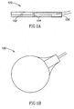
- Figs. 1A, 1B , and 1C respectively show side, back, and face views of a unit 100 which optionally combines a current electrode 102 and a voltage electrode 104 for impedance plethysmography (IPG), and a sensor 106 for photoplethysmography (PPG), according to an exemplary embodiment of the invention.
- the face side of unit 100 shown in Fig. 1C , is the side that is placed against the skin, as shown in Fig. 2 .
- two such units placed for example on opposite sides of the head, are optionally used for IPG, passing current from one unit to the other and measuring the voltage between them. For reasons described below, alternating current is generally used.
- PPG sensor 106 measures the color of the skin to determine a degree of perfusion of oxygenated blood in the skin adjacent to unit 100, as described, for example, by J. Webster, "Measurement of Flow and Volume of Blood," in John G. Webster (ed.), Medical Instrumentation: Application and Design (Wiley, 1997 ), the disclosure of which is incorporated herein by reference.
- PPG sensor 106 incorporates a digital signal processor which converts the raw sensor signal into a usable output signal.
- unit 100 also includes a digital signal processor which processes voltage and/or current and/or photo reflection data of the electrodes and/or PPG in one or both units.
- the raw signal from sensor 106 and/or data from the electrodes is processed partly or entirely by an external signal processor not located in unit 100.
- unit 100 instead of having separate current and voltage electrodes, unit 100 has a single electrode, used both for carrying current and for measuring voltage.
- a single electrode used both for carrying current and for measuring voltage.
- using separate electrodes for carrying current and measuring voltage has the potential advantage that the measured voltage may not be very sensitive to a high contact resistance between the electrodes and the skin, or to a high resistance across the epidermis, one or both of which can dominate the voltage drop between the current electrodes on opposite sides of the head.
- the contact resistance and the epidermis resistance have little or no dependence on blood flow, so it is generally desirable for the IPG signal not to be sensitive to the contact and epidermis resistance.
- This goal is optionally achieved by using an annular shape for current-electrode 102, and locating voltage-electrode 104 in the center of the annulus, but substantially electrically decoupled from it.
- the radial thickness of the annulus of electrode 102, and the gap between electrodes 102 and 104 are optionally at least somewhat greater than the thickness of the epidermis under the electrodes, for example at least twice as great.
- the radial thickness of the annulus of electrode 102 is at least 2 mm, or at least 5 mm, or at least 1 cm.
- the gap between electrodes 102 and 104 is at least 2 mm, or at least 5 mm, or at least 1 cm, or intermediate or smaller values.
- this potential difference depends on the impedance of the dermis of the temples and the scalp, and the impedance of the cranium and the brain, as described below in connection with Fig. 3 , rather than on the impedance across the epidermis.
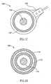
- FIG. 1D An alternative configuration 108 for the voltage and current electrodes is shown in Fig. 1D .
- Current is injected through electrode 110, located in the center, and voltage is measured at electrode 112, in the form of an annulus surrounding electrode 110, which is electrically well isolated from electrode 110.
- An additional electrode 114 also in the form of an annulus, surrounds electrode 112, and injects whatever current is necessary in order to remain at the same voltage as electrode 110.
- only the current injected through electrode 110 is considered for purposes of finding the impedance.
- the current from electrode 110 will be directed mostly into the head, and relatively more of this current will flow through the brain as opposed to flowing through the scalp, while most of the current flowing through the scalp will be injected by electrode 114, and may be ignored for purposes of measuring the impedance.
- the impedance measurement will be more sensitive to the impedance of the brain, and less sensitive to the impedance of the scalp.
- the thicknesses of electrodes 112 and 114, and the gaps between them and between electrodes 110 and 112 have the same possible dimensions as those mentioned above for electrodes 102 and 104.
- the current through electrode 114 is also measured, and compared to the current through electrode 110, in order to estimate the ratio of the scalp path impedance to the cerebral path impedance.
- This ratio may be used to find a weighting factor to be used for the PPG signal when subtracting the PPG signal from the IPG signal, instead of or in addition to the methods described above for finding the weighting factor.
- any of the electrode configurations described in US patent application 10/893,570 is used, or any other electrode configuration is used in which the current electrode is adjacent to the voltage electrode. If the current electrode has dimensions that are large compared to the thickness of the epidermis, and the voltage electrode is separated from the current electrode by a similar distance, then the voltage electrode will measure a potential that tends to be close to the potential at the dermis under the voltage and current electrodes, largely excluding the voltage drop across the epidermis.
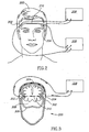
- Fig. 2 shows a head 200 with units 202 and 204 placed on the temples on each side of the head, according to an exemplary embodiment of the invention.
- each of units 202 and 204 is like unit 100 in Figs. 1A-1C , including both IPG electrodes and PPG sensors.
- a power supply 206 passes current between the current-electrodes in units 202 and 204, and a voltage difference is measured between the voltage-electrodes in units 202 and 204, while PPG data is optionally supplied by the PPG sensors in both units.
- a data analyzer 208 uses the voltage difference between the voltage electrodes, together with the PPG data, to estimate the cerebral blood flow, as will be described below in the description of Figs. 4 and 5 .
- a C-shaped spring device 210 connects units 202 and 204, and provides a force to keep units 202 and 204 in place on the temples, similar to headphones.
- suction cups such as those used for electrocardiographs, are used to keep units 202 and 204 in place on the temples, or any other method known in the art, for example an adhesive, is used to keep units 202 and 204 in place on the temples.
- units 202 and 204 are placed at other locations on the head, for example on the forehead and in the back of the head.
- the two electrodes need not be placed on opposite sides of the head, placing them on at least approximately opposite sides of the head has the potential advantage that relatively more current goes through the interior of the skull, rather than through the scalp.
- Placing the electrodes on the temples has the potential advantage that there is no need to shave the skin before placing the electrodes, and the skull is relatively thin at the temples, also causing relatively more of the current to go through the brain rather than through the scalp.
- Placing an electrode over one of the closed eyelids, or over the foramen magnum at the base of the skull, or over the ears or inside the ear canal also allows current to get into the interior of the skull relatively efficiently.
- Such an arrangement using impedance imaging algorithms, can provide additional information about the impedance distribution inside the head, but the data analysis is more complicated than with only two electrodes, and the electrodes take longer to place.
- the units generally use alternating current, for example in the frequency range of a few kilohertz to several tens of kilohertz. Frequencies above about 100 kHz may give impedance data that is less sensitive to blood flow than lower frequencies, since above about 100 kHz the currents can easily flow through the cell membranes, which act like capacitors, and across the interiors of the cells. At frequencies well below 100 kHz, the currents are largely confined to the extra-cellular fluid, and the impedance tends to be more sensitive to blood volume.
- Fig. 3 shows a cut-away view of head 200, seen from the front, with units 202 and 204 on the two temples, as in Fig. 2 .
- a cross-sectional cut has been made most of the way through the head in Fig. 3 , but in order to show the location of units 202 and 204 on the temples, the skin and skull of the temples have been left in place, in front of the cross-sectional cut.
- Current between the current electrodes in units 202 and 204 can travel on different paths.
- Scalp 302 has a relatively low resistivity beneath the epidermis, and a large part of the current travels through the scalp, on path 304, going around skull 306, which has a higher resistivity.
- Interior 308 of the skull also has a relatively low resistivity.
- the current electrodes are fairly wide, a significant part of the current goes through the skull and across the brain, on path 310, since the part of path 310 that goes through the high resistivity skull is relatively short and has wide cross-section, while path 304 through the lower resistivity scalp is much longer and has a much smaller cross-section.
- configuration 108 shown in Fig. 1D is used, then a relatively larger part of the current from electrode 110 will tend to go on path 310, through the brain, while a relatively larger part of the current from electrode 114 will tend to go on path 304, through the scalp.
- R B is the impedance along path 310 through the skull and brain
- R S is the impedance along path 304 through the scalp, which is parallel to path 310.
- Each of these impedances has a constant part which is independent of the phase of the cardiac cycle, and a much smaller part which varies with the phase of the cardiac cycle, due to the change in blood volume in the brain and in the scalp.
- R B R B ⁇ 0 + ⁇ ⁇ R B
- R S R S ⁇ 0 + ⁇ ⁇ R S
- ⁇ R the small time varying part of the impedance
- these impedances are mostly resistive at the frequencies typically used, well below 100 kHz, and this is especially true for the variations in the impedances over a cardiac cycle, since they depend on the volume of blood, which is located outside the cell membranes. Higher resistance is associated with a lower volume of blood, so - ⁇ R B and - ⁇ R S are measures respectively of change in cerebral blood volume, and change in blood volume in the scalp.
- the PPG signal also measures change in blood volume in the scalp, and is approximately a linear function of - ⁇ R S since the signals are small.
- the cerebral blood volume varies during a cardiac cycle because the arterial blood flow into the brain is pulsatile, while the venous blood flow out of the brain is approximately uniform in time. There is some blood flow into the brain even at the time of diastolic pressure, and this baseline cerebral blood flow cannot be determined directly by measuring changes in cerebral blood volume. However, since the time-varying component is a significant fraction of the total cerebral blood flow, measuring the change in cerebral blood volume during a cardiac cycle may provide a clinically useful relative measure of cerebral blood flow.
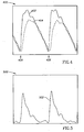
- Fig. 4 shows an exemplary plot 400 of the IPG signal - ⁇ R, labeled 402, shown as a solid curve, and a weighted PPG signal 404, shown as a dashed curve, as a function of time.
- Signals 402 and 404 are both plotted in arbitrary units, and alternatively signal 404 could be considered the original PPG signal and signal 402 could be weighted, or both signals could be weighted, since only their ratio matters in plot 400.
- An R-wave from an electrocardiogram, has peaks at times 406.
- IPG signal 402 and PPG signal 404 both start to rise, as blood flows into the brain and into the scalp, but the rise in the IPG signal starts earlier, and is much more rapid initially, than the rise in the PPG signal. This is believed to be due to the fact that the arteries supplying blood to the brain have a larger diameter, and lower hydrodynamic resistance to blood flow, than the small arteries supplying blood to the scalp. Later in each cardiac cycle, when the blood has had time to flow into the scalp, we expect the IPG signal to be dominated by the blood volume in the scalp.
- the weighting factor for PPG signal 404 has optionally been chosen so that weighted PPG signal 404 is approximately equal to IPG signal 402 during an interval late in each cardiac cycle, for example during the last third of each cardiac cycle, when the blood pressure and signals 402 and 404 are falling, before the next peak of the R-wave.
- the weighting factor is chosen by other methods which evaluate, at least approximately, the ratio of current through the cranium to current through the scalp.
- the weighting factor is set equal to the square root of the ratio of the power spectrum of the IPG signal, integrated over a range of frequencies, to the power spectrum of the PPG signal, integrated over the same range.
- the range of frequencies is a range within which the PPG signal is similar to the IPG signal, as indicated, for example, by a high cross-power spectrum between the IPG and PPG signals.
- the range of frequencies is centered at the peak of the cross-power spectrum, and extends to each side of the peak by an amount equal to or proportional to the rms width of the peak of the cross-power spectrum.
- the range of frequencies is defined to include all frequencies for which the cross-power spectrum is greater than a certain fraction (for example, half) of the geometric mean of the magnitudes of the IPG and PPG power spectra.
- the two power spectra are weighted within the range of frequencies, for example according to the value of the cross-power spectrum. In this case, the integration over frequency need not be over a limited range of frequencies.
- Fig. 5 shows a plot 500 of a signal 502 equal to the difference between IPG signal 402 and weighted PPG signal 404, as a function of time.
- the cerebral blood volume is estimated from the IPG signal alone but these embodiments do not form part of the invention . This may be justified because there is evidence that early in each cardiac cycle, and even up to the peak in the IPG signal, the time-dependent part of the IPG signal is largely dominated by changes in cerebral blood volume.
- Fig. 6 shows a plot 600 of an IPG signal 602, plotted as a solid line, and a PPG signal 604, plotted as a dashed line, measured while the subject was voluntarily hyperventilating. The hyperventilation produces large fluctuations in the peak value of the IPG signal from one cardiac cycle to another, and much smaller fluctuations in the peak value of the PPG signal from one cardiac cycle to another.
- the time dependence of the PPG signal is believed to be due almost entirely to changes in the scalp blood volume, the fact that the IPG signal behaves very differently from the PPG signal indicates that the IPG signal is not dominated by the changes in scalp blood volume, but by something else, presumably changes in cerebral blood volume.
- One method of estimating the time varying part of the cerebral blood volume is just to assume that the change in cerebral blood volume is proportional to the peak value of the IPG signal for each cardiac cycle.
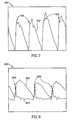
- Fig. 7 illustrates another method not forming part of the invention of estimating the changes in cerebral blood volume, again using only the IPG signal.
- Plot 700 shows an IPG signal 702 as a function of time, for four cardiac cycles. In each cardiac cycle, the value of the IPG signal is measured at its first local peak following the minimum (or following the peak in the R-wave, which occurs at about the same time as the minimum in the IPG signal). Optionally, if there is an inflection point in the IPG signal before the first local peak, then the value of the IPG signal is measured at the inflection point. This is true, for example, in the third cardiac cycle shown in plot 700. These values of the IPG signal for each cardiac cycle are indicated by small crosses 704 in plot 700.
- Using these values of the IPG signal in each cardiac cycle may better reflect the change in cerebral blood volume than using the peak IPG signal in each cardiac cycle. This may be true, for example, because these values occur earlier in each cardiac cycle, when the IPG signal is more dominated by the time-dependent part of the cerebral blood volume, and is less sensitive to the scalp blood volume.
- Fig. 8 illustrates yet another method not forming part of the invention of estimating the changes in cerebral blood volume, using only the IPG signal.
- Plot 800 shows an IPG signal 802 as a function of time, for three cardiac cycles, and a signal 804 proportional to the time derivative of IPG signal 802.
- the peak of signal 804, i.e. the peak rate of rise of IPG signal 802 is measured in each cardiac cycle, and indicated by small crosses 806 in plot 800.
- the peak value of signal 804 may be a good indication of the change in cerebral blood volume during that cardiac cycle, perhaps a better indication than the peak value of the IPG signal.
- the PPG signal is optionally recorded as well, for example to verify that the scalp blood volume is not changing very much early in each cardiac cycle, at the times when the IPG signal is used to estimate the change in cerebral blood volume.
- two or more of the methods illustrated in Figs. 5-8 are used to estimate the change in cerebral blood volume, for example by taking a weighted average of the change in cerebral blood volume determined by each method. Different methods might work best for different patients who have different medical conditions.
- a patient is suffering from a condition in which cerebral blood flow is likely to be reduced more than scalp blood flow
- the changes in scalp blood flow may dominate the IPG signal even early in the cardiac cycle, and it may be best to use the method illustrated in Fig. 5 , which makes use of both the IPG signal and the PPG signal.
- cerebral blood flow and scalp blood flow are likely to be reduced at the same time, for example in the case of a patient undergoing cardiac surgery, it may be better or easier to use one of the methods that depends only on the IPG signal.
Landscapes
- Health & Medical Sciences (AREA)
- Life Sciences & Earth Sciences (AREA)
- Physics & Mathematics (AREA)
- General Health & Medical Sciences (AREA)
- Veterinary Medicine (AREA)
- Engineering & Computer Science (AREA)
- Biomedical Technology (AREA)
- Heart & Thoracic Surgery (AREA)
- Medical Informatics (AREA)
- Molecular Biology (AREA)
- Surgery (AREA)
- Animal Behavior & Ethology (AREA)
- Biophysics (AREA)
- Public Health (AREA)
- Pathology (AREA)
- Hematology (AREA)
- Cardiology (AREA)
- Physiology (AREA)
- Otolaryngology (AREA)
- Electromagnetism (AREA)
- Nuclear Medicine, Radiotherapy & Molecular Imaging (AREA)
- Radiology & Medical Imaging (AREA)
- Measuring Pulse, Heart Rate, Blood Pressure Or Blood Flow (AREA)
- Measurement And Recording Of Electrical Phenomena And Electrical Characteristics Of The Living Body (AREA)
- Magnetic Resonance Imaging Apparatus (AREA)
- Medicines Containing Antibodies Or Antigens For Use As Internal Diagnostic Agents (AREA)
Applications Claiming Priority (2)
| Application Number | Priority Date | Filing Date | Title |
|---|---|---|---|
| US10/893,570 US7998080B2 (en) | 2002-01-15 | 2004-07-15 | Method for monitoring blood flow to brain |
| PCT/IL2005/000632 WO2006011128A1 (en) | 2004-07-15 | 2005-06-15 | Cerebral perfusion monitor |
Publications (3)
| Publication Number | Publication Date |
|---|---|
| EP1786316A1 EP1786316A1 (en) | 2007-05-23 |
| EP1786316A4 EP1786316A4 (en) | 2010-03-03 |
| EP1786316B1 true EP1786316B1 (en) | 2012-10-24 |
Family
ID=34972097
Family Applications (2)
| Application Number | Title | Priority Date | Filing Date |
|---|---|---|---|
| EP05752203A Expired - Lifetime EP1786316B1 (en) | 2004-07-15 | 2005-06-15 | Cerebral perfusion monitor |
| EP05750856A Expired - Lifetime EP1796536B1 (en) | 2004-07-15 | 2005-06-15 | Device for monitoring blood flow to brain |
Family Applications After (1)
| Application Number | Title | Priority Date | Filing Date |
|---|---|---|---|
| EP05750856A Expired - Lifetime EP1796536B1 (en) | 2004-07-15 | 2005-06-15 | Device for monitoring blood flow to brain |
Country Status (6)
| Country | Link |
|---|---|
| US (4) | US7998080B2 (enExample) |
| EP (2) | EP1786316B1 (enExample) |
| JP (1) | JP4842939B2 (enExample) |
| CN (2) | CN100566654C (enExample) |
| AT (1) | ATE536134T1 (enExample) |
| WO (1) | WO2006006143A1 (enExample) |
Families Citing this family (94)
| Publication number | Priority date | Publication date | Assignee | Title |
|---|---|---|---|---|
| US7117033B2 (en) * | 2000-05-08 | 2006-10-03 | Brainsgate, Ltd. | Stimulation for acute conditions |
| US7640062B2 (en) | 2000-05-08 | 2009-12-29 | Brainsgate Ltd. | Methods and systems for management of alzheimer's disease |
| US7146209B2 (en) * | 2000-05-08 | 2006-12-05 | Brainsgate, Ltd. | Stimulation for treating eye pathologies |
| US7998080B2 (en) * | 2002-01-15 | 2011-08-16 | Orsan Medical Technologies Ltd. | Method for monitoring blood flow to brain |
| US8211031B2 (en) * | 2002-01-15 | 2012-07-03 | Orsan Medical Technologies Ltd. | Non-invasive intracranial monitor |
| WO2006011128A1 (en) | 2004-07-15 | 2006-02-02 | Orsan Medical Technologies Ltd. | Cerebral perfusion monitor |
| EP1503734A2 (en) * | 2002-04-25 | 2005-02-09 | Brainsgate Ltd. | Methods and apparatus for modifying properties of the bbb and cerebral circulation by using the neuroexcitatory and/or neuroinhibitory effects of odorants on nerves in the head |
| US7684859B2 (en) * | 2002-04-25 | 2010-03-23 | Brainsgate Ltd. | Stimulation of the OTIC ganglion for treating medical conditions |
| EP1585430B1 (en) * | 2002-11-14 | 2017-01-11 | Brainsgate Ltd. | Surgical tools and techniques for stimulation |
| US7251521B2 (en) * | 2003-11-19 | 2007-07-31 | Igc Medical Advances, Inc. | Motion sensing MRI local coil |
| US8055347B2 (en) | 2005-08-19 | 2011-11-08 | Brainsgate Ltd. | Stimulation for treating brain events and other conditions |
| US9233245B2 (en) | 2004-02-20 | 2016-01-12 | Brainsgate Ltd. | SPG stimulation |
| US8010189B2 (en) * | 2004-02-20 | 2011-08-30 | Brainsgate Ltd. | SPG stimulation for treating complications of subarachnoid hemorrhage |
| JP4737496B2 (ja) * | 2004-07-06 | 2011-08-03 | ソニー株式会社 | 再生システム、再生装置および方法、記録媒体、並びにプログラム |
| US20090299418A1 (en) * | 2004-08-23 | 2009-12-03 | Brainsgate Ltd. | Concurrent bilateral spg modulation |
| GB0505244D0 (en) * | 2005-03-15 | 2005-04-20 | Ivmd Uk Ltd | Diagnostic apparatus |
| DE102005017818A1 (de) * | 2005-04-18 | 2006-10-26 | Siemens Ag | Verfahren und Vorrichtung zur nicht invasiven Untersuchung eines Objekts |
| ES2276609B1 (es) * | 2005-09-27 | 2008-06-16 | Universidad Politecnica De Valencia | Aparato y metodo de obtencion de informacion relativa a la hemodinamica cerebral. |
| US20090210026A1 (en) * | 2006-08-17 | 2009-08-20 | Brainsgate Ltd. | Spg stimulation for enhancing neurogenesis and brain metabolism |
| SG141274A1 (en) * | 2006-09-15 | 2008-04-28 | Nanyang Polytechnic | Packages of apparatus for non-invasive detection of pulse rate and blood flow anomalies |
| US7541602B2 (en) | 2007-06-04 | 2009-06-02 | Or-Nim Medical Ltd. | System and method for noninvasively monitoring conditions of a subject |
| US7860569B2 (en) | 2007-10-18 | 2010-12-28 | Brainsgate, Ltd. | Long-term SPG stimulation therapy for prevention of vascular dementia |
| US8750978B2 (en) * | 2007-12-31 | 2014-06-10 | Covidien Lp | System and sensor for early detection of shock or perfusion failure and technique for using the same |
| US8336391B2 (en) * | 2008-07-06 | 2012-12-25 | Or-Nim Medical Ltd. | Method and system for non-invasively monitoring fluid flow in a subject |
| US9027412B2 (en) | 2008-07-06 | 2015-05-12 | Or-Nim Medical Ltd. | Method and system for non-invasively monitoring fluid flow in a subject |
| DE102008040788A1 (de) * | 2008-07-28 | 2010-02-11 | Biotronik Crm Patent Ag | Vorrichtung und Verfahren zur Erfassung der Strömungsgeschwindigkeit eines Blutstromes und Herz-/Kreislauf-Unterstützungsvorrichtung |
| WO2010030225A1 (en) * | 2008-09-09 | 2010-03-18 | Fernando Seoane Martinez | Method and apparatus for brain damage detection |
| WO2010042653A1 (en) | 2008-10-07 | 2010-04-15 | Mc10, Inc. | Catheter balloon having stretchable integrated circuitry and sensor array |
| US8097926B2 (en) | 2008-10-07 | 2012-01-17 | Mc10, Inc. | Systems, methods, and devices having stretchable integrated circuitry for sensing and delivering therapy |
| US8886334B2 (en) * | 2008-10-07 | 2014-11-11 | Mc10, Inc. | Systems, methods, and devices using stretchable or flexible electronics for medical applications |
| JP2012505012A (ja) * | 2008-10-07 | 2012-03-01 | オルサン メディカル テクノロジーズ リミテッド | 急性脳卒中の診断 |
| US20100112614A1 (en) * | 2008-11-06 | 2010-05-06 | Physical Logic Ag | Coupled Antenna Impedance Spectroscopy |
| US9138161B2 (en) * | 2008-11-18 | 2015-09-22 | Qualcomm Incorporated | Methods, apparatus and sensor for measurement of cardiovascular quantities |
| WO2011041727A1 (en) | 2009-10-01 | 2011-04-07 | Mc10, Inc. | Protective cases with integrated electronics |
| US20110218756A1 (en) * | 2009-10-01 | 2011-09-08 | Mc10, Inc. | Methods and apparatus for conformal sensing of force and/or acceleration at a person's head |
| AU2010315490B2 (en) * | 2009-10-28 | 2015-02-12 | The Board Of Governors For Higher Education, State Of Rhode Island And Providence Plantations | Biomedical electrode |
| RU2427313C1 (ru) * | 2010-02-24 | 2011-08-27 | Государственное образовательное учреждение дополнительного профессионального образования "Новокузнецкий государственный институт усовершенствования врачей Федерального агентства по здравоохранению и социальному развитию" | Способ проведения обследования при синдроме головной боли у детей |
| JP5717064B2 (ja) * | 2011-02-03 | 2015-05-13 | 国立大学法人 筑波大学 | 血流計測装置及び血流計測装置を用いた脳活動計測装置 |
| US20120203121A1 (en) * | 2011-02-09 | 2012-08-09 | Opher Kinrot | Devices and methods for monitoring cerebral hemodynamic characteristics |
| US20130041271A1 (en) * | 2011-04-12 | 2013-02-14 | Shlomi Ben-Ari | Devices and methods for monitoring intracranial pressure and additional intracranial hemodynamic parameters |
| JP5382666B2 (ja) * | 2011-04-21 | 2014-01-08 | 学校法人 聖マリアンナ医科大学 | 濃度測定装置及び濃度測定方法 |
| JP2014523633A (ja) | 2011-05-27 | 2014-09-11 | エムシー10 インコーポレイテッド | 電子的、光学的、且つ/又は機械的装置及びシステム並びにこれらの装置及びシステムを製造する方法 |
| CN102283640A (zh) * | 2011-07-22 | 2011-12-21 | 天津万安康泰医疗科技有限公司 | 数字脑阻抗血流图仪 |
| CN102293645A (zh) * | 2011-08-22 | 2011-12-28 | 天津万安康泰医疗科技有限公司 | 数字阻抗法肺循环血流动力学监测仪 |
| EP2786131B1 (en) * | 2011-09-01 | 2018-11-07 | Mc10, Inc. | Electronics for detection of a condition of tissue |
| JP5893886B2 (ja) * | 2011-10-07 | 2016-03-23 | 日本光電工業株式会社 | インピーダンス測定装置 |
| US11357417B2 (en) | 2012-01-19 | 2022-06-14 | Cerebrotech Medical Systems, Inc. | Continuous autoregulation system |
| JP6224006B2 (ja) | 2012-01-19 | 2017-11-01 | セレブロテック メディカル システムズ インコーポレイテッド | 流体変化を検出するための診断システム |
| US10743815B2 (en) * | 2012-01-19 | 2020-08-18 | Cerebrotech Medical Systems, Inc. | Detection and analysis of spatially varying fluid levels using magnetic signals |
| JP5244988B1 (ja) * | 2012-02-20 | 2013-07-24 | 浜松ホトニクス株式会社 | 濃度測定装置および濃度測定方法 |
| JP5238087B1 (ja) * | 2012-02-20 | 2013-07-17 | 浜松ホトニクス株式会社 | 濃度測定装置および濃度測定方法 |
| US20130274615A1 (en) * | 2012-04-12 | 2013-10-17 | Shlomi Ben-Ari | Measurement of Cerebral Physiologic Parameters Using Bioimpedance |
| WO2014022683A1 (en) | 2012-08-03 | 2014-02-06 | Zoll Medical Corporation | Arterial and venous blood metrics |
| US10881310B2 (en) | 2012-08-25 | 2021-01-05 | The Board Of Trustees Of The Leland Stanford Junior University | Motion artifact mitigation methods and devices for pulse photoplethysmography |
| US9171794B2 (en) | 2012-10-09 | 2015-10-27 | Mc10, Inc. | Embedding thin chips in polymer |
| CN103919554A (zh) * | 2013-01-16 | 2014-07-16 | 李茗 | 内耳淋巴液的磁共振新技术 |
| CN105142501B (zh) * | 2013-03-06 | 2019-02-01 | 皇家飞利浦有限公司 | 用于确定生命体征信息的系统和方法 |
| IL275793B (en) * | 2013-03-15 | 2022-08-01 | Univ California | Multifrequency signal processing classifiers for determining a tissue condition |
| JP6006668B2 (ja) * | 2013-03-29 | 2016-10-12 | 浜松ホトニクス株式会社 | 濃度測定装置および濃度測定方法 |
| EP2878335B1 (en) | 2013-11-10 | 2018-01-03 | Brainsgate Ltd. | Implant and delivery system for neural stimulator |
| EP3111837B1 (en) * | 2014-02-25 | 2020-10-28 | School Juridical Person The Kitasato Institute | Image generating device and image generating method |
| US9320451B2 (en) | 2014-02-27 | 2016-04-26 | Kimberly-Clark Worldwide, Inc. | Methods for assessing health conditions using single coil magnetic induction tomography imaging |
| WO2015134765A2 (en) * | 2014-03-07 | 2015-09-11 | Zoll Circulation, Inc. | Endovascular heat exchange systems and methods with blood flow monitoring and notification functions |
| AU2015311843B2 (en) * | 2014-09-03 | 2020-05-21 | Cerebrotech Medical Systems, Inc. | Detection and analysis of spatially varying fluid levels using magnetic signals |
| KR102420009B1 (ko) * | 2015-04-08 | 2022-07-12 | 삼성전자주식회사 | 생체 정보 측정 장치 |
| US10271907B2 (en) | 2015-05-13 | 2019-04-30 | Brainsgate Ltd. | Implant and delivery system for neural stimulator |
| US10660604B2 (en) * | 2015-07-13 | 2020-05-26 | Otonexus Medical Technologies, Inc. | Apparatus and method for characterization of acute otitis media |
| US10585150B2 (en) | 2015-10-06 | 2020-03-10 | The Charles Stark Draper Laboratory, Inc. | Magnetic field detector system |
| US10564200B2 (en) | 2015-10-06 | 2020-02-18 | The Charles Stark Draper Laboratory, Inc. | Electric field detector system |
| US20160129238A1 (en) * | 2016-01-14 | 2016-05-12 | Joel Steven Goldberg | Method to optimize electrode placement for cranial electrical stmulation |
| US10874315B2 (en) * | 2016-03-30 | 2020-12-29 | Zoll Medical Corporation | Non-invasive blood flow measurement |
| WO2018064554A1 (en) * | 2016-09-30 | 2018-04-05 | The Charles Stark Draper Laboratory, Inc. | Biophysical sensing systems and methods using non-contact electric field detectors |
| JP6399528B2 (ja) * | 2017-03-30 | 2018-10-03 | 学校法人 聖マリアンナ医科大学 | 濃度測定装置及び濃度測定装置の作動方法 |
| US10859620B2 (en) | 2017-04-04 | 2020-12-08 | The Charles Stark Draper Laboratory, Inc. | Miniature electric field detector |
| EP3624890B1 (en) * | 2017-05-16 | 2024-06-19 | The Regents Of The University Of Michigan | Ocular impedance-based system for brain health monitoring |
| US11525870B2 (en) | 2017-10-05 | 2022-12-13 | The Charles Stark Draper Laboratory, Inc. | Electromagnetic gradiometers |
| US12082946B2 (en) * | 2018-02-20 | 2024-09-10 | Yukka Magic Llc | Ear gel modules and earpiece monitoring devices incorporating same |
| EP3603499A1 (en) * | 2018-08-03 | 2020-02-05 | Nokia Technologies Oy | Providing an output relating to conductivity distribution |
| WO2020056025A1 (en) | 2018-09-12 | 2020-03-19 | California Institute Of Technology | A wearable inductive damping sensor |
| CN109717861A (zh) * | 2018-12-28 | 2019-05-07 | 华中科技大学鄂州工业技术研究院 | 一种血流速度的激光散斑检测方法及检测装置 |
| EP3917389A4 (en) * | 2019-01-31 | 2022-11-02 | Flow CPR Inc. | DEVICE AND METHOD FOR CALCULATION OF A VOLUME FLOW RATE OF OXYGENATED BLOOD |
| US12089941B2 (en) | 2019-03-15 | 2024-09-17 | The Charles Stark Draper Laboratory, Inc. | Miniature electric field detector |
| WO2021081443A1 (en) * | 2019-10-23 | 2021-04-29 | Trustees Of Dartmouth College | System and methods for impedance-based non-invasive intracranial monitoring |
| CN115552201A (zh) | 2020-02-19 | 2022-12-30 | 加州理工学院 | 感应阻尼大脑传感器 |
| CN111528829A (zh) * | 2020-05-25 | 2020-08-14 | 陈聪 | 一种用于检测脑血管健康状况的系统和方法 |
| FR3111062A1 (fr) * | 2020-06-04 | 2021-12-10 | Fabrinal Sa | Dispositif médical d’examen oculaire |
| CN112535486B (zh) * | 2020-09-23 | 2021-07-02 | 清华大学 | 基于smp的螺旋形监测脑电装置及其制备方法 |
| JP7128490B2 (ja) * | 2020-12-08 | 2022-08-31 | メディカル・イノベイション株式会社 | 測定装置、その動作方法および動作プログラム |
| GB202108374D0 (en) * | 2021-06-11 | 2021-07-28 | Cyqiq Ltd | Impendance tomography |
| CN113812938A (zh) * | 2021-08-23 | 2021-12-21 | 中国人民解放军陆军军医大学 | 一种基于电感遥测技术的脑血流监测装置 |
| TWI797901B (zh) * | 2021-12-21 | 2023-04-01 | 財團法人工業技術研究院 | 電生理訊號量測系統、電生理訊號調節方法與電極組件 |
| US12004874B2 (en) | 2022-10-24 | 2024-06-11 | Applied Cognition, Inc. | Wearable device and method for non-invasive assessment of glymphatic flow |
| WO2024182066A1 (en) | 2023-03-01 | 2024-09-06 | StrokeDx, Inc. | Coil positioning system for noninvasive brain sensor |
| TWI891014B (zh) * | 2023-06-16 | 2025-07-21 | 國立清華大學 | 耳戴式渦電流量測裝置及耳戴式感測器 |
Family Cites Families (63)
| Publication number | Priority date | Publication date | Assignee | Title |
|---|---|---|---|---|
| US3835839A (en) * | 1972-12-08 | 1974-09-17 | Systron Donner Corp | Impedance plethysmograph and flow rate computer adjunct and method for use therewith |
| US3994284A (en) * | 1975-12-31 | 1976-11-30 | Systron Donner Corporation | Flow rate computer adjunct for use with an impedance plethysmograph and method |
| GB1538695A (en) | 1977-01-17 | 1979-01-24 | Biotron Medical Products Ltd | Method and apparatus for continuously monitoring systolic blood pressure |
| US4308873A (en) * | 1978-03-16 | 1982-01-05 | National Research Development Corporation | Electroencephalograph monitoring |
| US4417581A (en) * | 1979-05-23 | 1983-11-29 | The University Of Florida | Corneal electrode for electroretinography |
| US4676253A (en) * | 1985-07-18 | 1987-06-30 | Doll Medical Research, Inc. | Method and apparatus for noninvasive determination of cardiac output |
| JPS6382623A (ja) * | 1986-09-27 | 1988-04-13 | 日立建機株式会社 | 頭蓋内圧の測定装置 |
| JPH073444B2 (ja) | 1987-10-27 | 1995-01-18 | 株式会社日本システム研究所 | 導電性測定装置 |
| US5040540A (en) * | 1988-08-24 | 1991-08-20 | Nims, Inc. | Method and apparatus for non-invasive monitoring of central venous pressure, and improved transducer therefor |
| US4905705A (en) * | 1989-03-03 | 1990-03-06 | Research Triangle Institute | Impedance cardiometer |
| JPH03118038A (ja) | 1989-09-29 | 1991-05-20 | Agency Of Ind Science & Technol | 簡易型脳機能変化測定装置 |
| SE465551B (sv) * | 1990-02-16 | 1991-09-30 | Aake Oeberg | Anordning foer bestaemning av en maenniskas hjaert- och andningsfrekvens genom fotopletysmografisk maetning |
| SE466987B (sv) * | 1990-10-18 | 1992-05-11 | Stiftelsen Ct Foer Dentaltekni | Anordning foer djupselektiv icke-invasiv, lokal maetning av elektrisk impedans i organiska och biologiska material samt prob foer maetning av elektrisk impedans |
| JPH0817771B2 (ja) | 1991-05-31 | 1996-02-28 | 工業技術院長 | インピーダンス計測用電極 |
| US5282840A (en) * | 1992-03-26 | 1994-02-01 | Medtronic, Inc. | Multiple frequency impedance measurement system |
| GB9222888D0 (en) * | 1992-10-30 | 1992-12-16 | British Tech Group | Tomography |
| US5265615A (en) * | 1992-12-18 | 1993-11-30 | Eyal Frank | Method and apparatus for continuous measurement of cardiac output and SVR |
| AU1328595A (en) * | 1994-06-20 | 1996-01-15 | Auckland Uniservices Limited | Brain damage monitor |
| US5725471A (en) | 1994-11-28 | 1998-03-10 | Neotonus, Inc. | Magnetic nerve stimulator for exciting peripheral nerves |
| US5817030A (en) * | 1995-04-07 | 1998-10-06 | University Of Miami | Method and apparatus for controlling a device based on spatial discrimination of skeletal myopotentials |
| US6117089A (en) * | 1995-04-25 | 2000-09-12 | The Regents Of The University Of California | Method for noninvasive intracranial pressure measurement |
| US5694939A (en) * | 1995-10-03 | 1997-12-09 | The United States Of America As Represented By The Administrator Of The National Aeronautics And Space Administration | Autogenic-feedback training exercise (AFTE) method and system |
| RU2141249C1 (ru) | 1996-01-19 | 1999-11-20 | Лебедева Валентина Дмитриевна | Способ диагностики и прогнозирования гипертонической болезни у людей до 30- летнего возраста |
| US5749369A (en) * | 1996-08-09 | 1998-05-12 | R.S. Medical Monitoring Ltd. | Method and device for stable impedance plethysmography |
| DE19635038A1 (de) * | 1996-08-29 | 1998-03-12 | Pulsion Verwaltungs Gmbh & Co | Verfahren zur nicht invasiven Bestimmung des zerebralen Blutflusses mittels Nah-Infrarot-Spektroskopie |
| US6544193B2 (en) * | 1996-09-04 | 2003-04-08 | Marcio Marc Abreu | Noninvasive measurement of chemical substances |
| US5788643A (en) * | 1997-04-22 | 1998-08-04 | Zymed Medical Instrumentation, Inc. | Process for monitoring patients with chronic congestive heart failure |
| US6169914B1 (en) * | 1998-01-13 | 2001-01-02 | Urometrics, Inc. | Devices and methods for monitoring female arousal |
| US6245027B1 (en) * | 1998-04-10 | 2001-06-12 | Noam Alperin | Method of measuring intracranial pressure |
| WO2000017615A2 (en) * | 1998-09-23 | 2000-03-30 | Keith Bridger | Physiological sensing device |
| JP2000325324A (ja) | 1999-05-21 | 2000-11-28 | Citizen Watch Co Ltd | 体脂肪率測定装置 |
| NO311747B1 (no) | 1999-05-31 | 2002-01-21 | Laerdal Medical As | Fremgangsmåte for å bestemme om en livlös person har puls, basert på impedansmåling mellom elektroder plassert på pasientenshud, hvor elektrodene er tilkoblet en ekstern defibrillator sittimpedansmålesystem, samt system for utförelse av fremga |
| US6413223B1 (en) * | 1999-06-01 | 2002-07-02 | Massachussetts Institute Of Technology | Cuffless continuous blood pressure monitor |
| US6640121B1 (en) * | 1999-08-10 | 2003-10-28 | The University Of Miami | Otic microprobe for neuro-cochlear monitoring |
| JP2001104274A (ja) | 1999-10-14 | 2001-04-17 | Shikoku Instrumentation Co Ltd | 生体インピーダンス計測装置用電極 |
| JP2002010986A (ja) | 2000-06-29 | 2002-01-15 | Yoshinaga Kajimoto | 脳内血液量の非侵襲的測定装置 |
| US7104958B2 (en) * | 2001-10-01 | 2006-09-12 | New Health Sciences, Inc. | Systems and methods for investigating intracranial pressure |
| US6819950B2 (en) * | 2000-10-06 | 2004-11-16 | Alexander K. Mills | Method for noninvasive continuous determination of physiologic characteristics |
| US20040030258A1 (en) * | 2000-10-09 | 2004-02-12 | Williams Christopher Edward | Sensor assembly for monitoring an infant brain |
| WO2002043564A2 (en) * | 2000-11-28 | 2002-06-06 | Allez Physionix Limited | Systems and methods for making non-invasive physiological assessments |
| DE10061189A1 (de) | 2000-12-08 | 2002-06-27 | Ingo Stoermer | Verfahren zur kontinuierlichen, nicht-invasiven Bestimmung des arteriellen Blutdrucks |
| AU2002254177A1 (en) | 2001-03-12 | 2002-09-24 | Active Signal Technologies | Brain assessment monitor |
| WO2002087410A2 (en) | 2001-04-27 | 2002-11-07 | Yacov Naisberg | Diagnosis, treatment and research of mental disorders |
| JP2005500116A (ja) | 2001-08-24 | 2005-01-06 | グルコセンス、インコーポレイテッド | 生体信号センサと、そのセンサに関連したアプリケーションを組み入れた生体信号を記録するための装置 |
| US6832113B2 (en) * | 2001-11-16 | 2004-12-14 | Cardiac Pacemakers, Inc. | Non-invasive method and apparatus for cardiac pacemaker pacing parameter optimization and monitoring of cardiac dysfunction |
| US7998080B2 (en) | 2002-01-15 | 2011-08-16 | Orsan Medical Technologies Ltd. | Method for monitoring blood flow to brain |
| US8211031B2 (en) * | 2002-01-15 | 2012-07-03 | Orsan Medical Technologies Ltd. | Non-invasive intracranial monitor |
| WO2006011128A1 (en) | 2004-07-15 | 2006-02-02 | Orsan Medical Technologies Ltd. | Cerebral perfusion monitor |
| WO2003059164A2 (en) | 2002-01-15 | 2003-07-24 | Orsan Medical Equipment Ltd. | Device for monitoring blood flow to brain |
| WO2006134501A1 (en) | 2005-06-15 | 2006-12-21 | Orsan Medical Technologies Ltd. | Cerebral perfusion monitor |
| US6773407B2 (en) * | 2002-04-08 | 2004-08-10 | The United States Of America As Represented By The Administrator Of The National Aeronautics And Space Administration | Non-invasive method of determining absolute intracranial pressure |
| US20040010185A1 (en) | 2002-07-11 | 2004-01-15 | Optical Sensors, Inc. | Method for measuring a physiologic parameter using a preferred site |
| US6763256B2 (en) * | 2002-08-16 | 2004-07-13 | Optical Sensors, Inc. | Pulse oximeter |
| US6976963B2 (en) * | 2002-09-30 | 2005-12-20 | Clift Vaughan L | Apparatus and method for precision vital signs determination |
| AU2003286457A1 (en) * | 2002-10-17 | 2004-05-04 | The General Hospital Corporation | Arrangement and method for detecting abnormalities and inconsistencies in a body |
| AU2003295943A1 (en) * | 2002-11-21 | 2004-06-18 | General Hospital Corporation | Apparatus and method for ascertaining and recording electrophysiological signals |
| AU2004236588B2 (en) * | 2003-05-12 | 2009-07-09 | Cheetah Medical, Inc. | System, method and apparatus for measuring blood flow and blood volume |
| US6966428B1 (en) * | 2003-12-24 | 2005-11-22 | Owens-Brockway Glass Container Inc. | Method and apparatus for transferring articles from a first position to a second position |
| US9820658B2 (en) * | 2006-06-30 | 2017-11-21 | Bao Q. Tran | Systems and methods for providing interoperability among healthcare devices |
| US8062224B2 (en) * | 2004-10-28 | 2011-11-22 | Uab Vittamed | Method and apparatus for non-invasive continuous monitoring of cerebrovascular autoregulation state |
| WO2006076361A2 (en) * | 2005-01-14 | 2006-07-20 | Brainard Ii Edward C | Bilateral differential pulse method for measuring brain activity |
| AU2006215274B2 (en) | 2005-02-15 | 2011-12-22 | Cheetah Medical, Inc. | System, method and apparatus for measuring blood flow and blood volume |
| JP2012505012A (ja) | 2008-10-07 | 2012-03-01 | オルサン メディカル テクノロジーズ リミテッド | 急性脳卒中の診断 |
-
2004
- 2004-07-15 US US10/893,570 patent/US7998080B2/en not_active Expired - Fee Related
-
2005
- 2005-06-15 CN CNB2005800310882A patent/CN100566654C/zh not_active Expired - Fee Related
- 2005-06-15 EP EP05752203A patent/EP1786316B1/en not_active Expired - Lifetime
- 2005-06-15 WO PCT/IL2005/000631 patent/WO2006006143A1/en not_active Ceased
- 2005-06-15 US US11/572,157 patent/US8702615B2/en not_active Expired - Fee Related
- 2005-06-15 JP JP2007520968A patent/JP4842939B2/ja not_active Expired - Fee Related
- 2005-06-15 EP EP05750856A patent/EP1796536B1/en not_active Expired - Lifetime
- 2005-06-15 CN CN2005800310897A patent/CN101052344B/zh not_active Expired - Fee Related
- 2005-06-15 AT AT05750856T patent/ATE536134T1/de active
-
2011
- 2011-06-22 US US13/165,890 patent/US20110251503A1/en not_active Abandoned
-
2014
- 2014-03-05 US US14/197,394 patent/US20140358016A1/en not_active Abandoned
Also Published As
| Publication number | Publication date |
|---|---|
| CN101052344B (zh) | 2012-07-04 |
| WO2006006143A1 (en) | 2006-01-19 |
| EP1786316A1 (en) | 2007-05-23 |
| US20080200787A1 (en) | 2008-08-21 |
| US8702615B2 (en) | 2014-04-22 |
| CN100566654C (zh) | 2009-12-09 |
| JP4842939B2 (ja) | 2011-12-21 |
| US7998080B2 (en) | 2011-08-16 |
| US20050054939A1 (en) | 2005-03-10 |
| US20110251503A1 (en) | 2011-10-13 |
| ATE536134T1 (de) | 2011-12-15 |
| EP1796536A1 (en) | 2007-06-20 |
| US20140358016A1 (en) | 2014-12-04 |
| EP1796536B1 (en) | 2011-12-07 |
| CN101052344A (zh) | 2007-10-10 |
| CN101052347A (zh) | 2007-10-10 |
| EP1786316A4 (en) | 2010-03-03 |
| JP2008506444A (ja) | 2008-03-06 |
Similar Documents
| Publication | Publication Date | Title |
|---|---|---|
| EP1786316B1 (en) | Cerebral perfusion monitor | |
| US8187197B2 (en) | Cerebral perfusion monitor | |
| CN102238905B (zh) | 脑血液动力学参数的测量 | |
| US5807270A (en) | Brain damage monitor | |
| JP5325115B2 (ja) | 非侵襲性頭蓋内モニタ | |
| US8277385B2 (en) | Method and apparatus for non-invasive assessment of hemodynamic and functional state of the brain | |
| US7011631B2 (en) | Noninvasive method of measuring blood density and hematocrit | |
| Bodo | Studies in rheoencephalography (REG) | |
| Michaeli et al. | Tissue resonance analysis: a novel method for noninvasive monitoring of intracranial pressure | |
| EP1895902B1 (en) | Cerebral perfusion monitor | |
| Bernjak et al. | Pulse transit times to the capillary bed evaluated by laser Doppler flowmetry | |
| Basano et al. | Pulsatile electrical impedance response from cerebrally dead adultpatients is not a reliable tool for detecting cerebral perfusion changes | |
| Ramesh et al. | Neuromonitoring | |
| He et al. | Wavelet analysis of cerebral oxygenation oscillations in the screening of Moyamoya disease | |
| Kamenik | The influence of left lateral position on cardiac output changes after head up tilt measured by impedance cardiography | |
| Meijer et al. | Assessing cardiac preload by the Initial Systolic Time Interval obtained from impedance cardiography | |
| Wong et al. | Assessment of Cerebral Oxygenation Response to Hemodialysis using Near-Infrared Spectroscopy (NIRS): Challenges and Solutions | |
| Mani et al. | Advanced neurological monitoring | |
| Krakauskaitė | Assessment of a non-invasive electronic cerebrovascular autoregulation monitoring system | |
| Sances Jr et al. | Non-Intrusive Evaluation of Trauma Patients | |
| Selmaoui | Acute exposure to mobile phone and assessment of internal cerebral circulation in young healthy subjects: A Transcranial Doppler study | |
| Hardin et al. | Application of dynamic optical tomography for the detection of a multi-phase physiologic response to Valsalva maneuver in healthy and diseased breast tissue | |
| Ghosn et al. | Acute exposure to mobile phone and assessment of internal cerebral circulation in young healthy subjects: a transcranial Doppler study | |
| Lediju | Thermal-based probe for testing endothelial dysfunction and possible implications for diagnosing atherosclerosis |
Legal Events
| Date | Code | Title | Description |
|---|---|---|---|
| PUAI | Public reference made under article 153(3) epc to a published international application that has entered the european phase |
Free format text: ORIGINAL CODE: 0009012 |
|
| 17P | Request for examination filed |
Effective date: 20070215 |
|
| AK | Designated contracting states |
Kind code of ref document: A1 Designated state(s): AT BE BG CH CY CZ DE DK EE ES FI FR GB GR HU IE IS IT LI LT LU MC NL PL PT RO SE SI SK TR |
|
| DAX | Request for extension of the european patent (deleted) | ||
| RIN1 | Information on inventor provided before grant (corrected) |
Inventor name: BEN-ARI, SHLOMI Inventor name: REICHMAN, YOSEF Inventor name: RAPPAPORT, ALON Inventor name: SHAPIRA, AHARON Inventor name: BARNEA, OFER |
|
| A4 | Supplementary search report drawn up and despatched |
Effective date: 20100128 |
|
| 17Q | First examination report despatched |
Effective date: 20100602 |
|
| REG | Reference to a national code |
Ref country code: DE Ref legal event code: R079 Ref document number: 602005036690 Country of ref document: DE Free format text: PREVIOUS MAIN CLASS: A61B0005000000 Ipc: A61B0005026000 |
|
| RIC1 | Information provided on ipc code assigned before grant |
Ipc: A61B 5/053 20060101ALI20120405BHEP Ipc: A61B 5/026 20060101AFI20120405BHEP Ipc: A61B 5/04 20060101ALI20120405BHEP |
|
| GRAP | Despatch of communication of intention to grant a patent |
Free format text: ORIGINAL CODE: EPIDOSNIGR1 |
|
| RIN1 | Information on inventor provided before grant (corrected) |
Inventor name: BEN-ARI, SHLOMI Inventor name: RAPPAPORT, ALON Inventor name: SHAPIRA, AHARON Inventor name: REICHMAN, YOSEF Inventor name: BARNEA, OFER |
|
| GRAS | Grant fee paid |
Free format text: ORIGINAL CODE: EPIDOSNIGR3 |
|
| GRAA | (expected) grant |
Free format text: ORIGINAL CODE: 0009210 |
|
| AK | Designated contracting states |
Kind code of ref document: B1 Designated state(s): AT BE BG CH CY CZ DE DK EE ES FI FR GB GR HU IE IS IT LI LT LU MC NL PL PT RO SE SI SK TR |
|
| REG | Reference to a national code |
Ref country code: GB Ref legal event code: FG4D |
|
| REG | Reference to a national code |
Ref country code: CH Ref legal event code: EP |
|
| REG | Reference to a national code |
Ref country code: AT Ref legal event code: REF Ref document number: 580449 Country of ref document: AT Kind code of ref document: T Effective date: 20121115 |
|
| REG | Reference to a national code |
Ref country code: IE Ref legal event code: FG4D |
|
| REG | Reference to a national code |
Ref country code: DE Ref legal event code: R096 Ref document number: 602005036690 Country of ref document: DE Effective date: 20121227 |
|
| REG | Reference to a national code |
Ref country code: AT Ref legal event code: MK05 Ref document number: 580449 Country of ref document: AT Kind code of ref document: T Effective date: 20121024 |
|
| REG | Reference to a national code |
Ref country code: NL Ref legal event code: VDEP Effective date: 20121024 |
|
| PG25 | Lapsed in a contracting state [announced via postgrant information from national office to epo] |
Ref country code: FI Free format text: LAPSE BECAUSE OF FAILURE TO SUBMIT A TRANSLATION OF THE DESCRIPTION OR TO PAY THE FEE WITHIN THE PRESCRIBED TIME-LIMIT Effective date: 20121024 Ref country code: IS Free format text: LAPSE BECAUSE OF FAILURE TO SUBMIT A TRANSLATION OF THE DESCRIPTION OR TO PAY THE FEE WITHIN THE PRESCRIBED TIME-LIMIT Effective date: 20130224 Ref country code: NL Free format text: LAPSE BECAUSE OF FAILURE TO SUBMIT A TRANSLATION OF THE DESCRIPTION OR TO PAY THE FEE WITHIN THE PRESCRIBED TIME-LIMIT Effective date: 20121024 Ref country code: SE Free format text: LAPSE BECAUSE OF FAILURE TO SUBMIT A TRANSLATION OF THE DESCRIPTION OR TO PAY THE FEE WITHIN THE PRESCRIBED TIME-LIMIT Effective date: 20121024 |
|
| PG25 | Lapsed in a contracting state [announced via postgrant information from national office to epo] |
Ref country code: PL Free format text: LAPSE BECAUSE OF FAILURE TO SUBMIT A TRANSLATION OF THE DESCRIPTION OR TO PAY THE FEE WITHIN THE PRESCRIBED TIME-LIMIT Effective date: 20121024 Ref country code: PT Free format text: LAPSE BECAUSE OF FAILURE TO SUBMIT A TRANSLATION OF THE DESCRIPTION OR TO PAY THE FEE WITHIN THE PRESCRIBED TIME-LIMIT Effective date: 20130225 Ref country code: SI Free format text: LAPSE BECAUSE OF FAILURE TO SUBMIT A TRANSLATION OF THE DESCRIPTION OR TO PAY THE FEE WITHIN THE PRESCRIBED TIME-LIMIT Effective date: 20121024 Ref country code: CY Free format text: LAPSE BECAUSE OF FAILURE TO SUBMIT A TRANSLATION OF THE DESCRIPTION OR TO PAY THE FEE WITHIN THE PRESCRIBED TIME-LIMIT Effective date: 20121024 Ref country code: GR Free format text: LAPSE BECAUSE OF FAILURE TO SUBMIT A TRANSLATION OF THE DESCRIPTION OR TO PAY THE FEE WITHIN THE PRESCRIBED TIME-LIMIT Effective date: 20130125 Ref country code: BE Free format text: LAPSE BECAUSE OF FAILURE TO SUBMIT A TRANSLATION OF THE DESCRIPTION OR TO PAY THE FEE WITHIN THE PRESCRIBED TIME-LIMIT Effective date: 20121024 |
|
| PG25 | Lapsed in a contracting state [announced via postgrant information from national office to epo] |
Ref country code: AT Free format text: LAPSE BECAUSE OF FAILURE TO SUBMIT A TRANSLATION OF THE DESCRIPTION OR TO PAY THE FEE WITHIN THE PRESCRIBED TIME-LIMIT Effective date: 20121024 |
|
| PG25 | Lapsed in a contracting state [announced via postgrant information from national office to epo] |
Ref country code: SK Free format text: LAPSE BECAUSE OF FAILURE TO SUBMIT A TRANSLATION OF THE DESCRIPTION OR TO PAY THE FEE WITHIN THE PRESCRIBED TIME-LIMIT Effective date: 20121024 Ref country code: DK Free format text: LAPSE BECAUSE OF FAILURE TO SUBMIT A TRANSLATION OF THE DESCRIPTION OR TO PAY THE FEE WITHIN THE PRESCRIBED TIME-LIMIT Effective date: 20121024 Ref country code: EE Free format text: LAPSE BECAUSE OF FAILURE TO SUBMIT A TRANSLATION OF THE DESCRIPTION OR TO PAY THE FEE WITHIN THE PRESCRIBED TIME-LIMIT Effective date: 20121024 Ref country code: BG Free format text: LAPSE BECAUSE OF FAILURE TO SUBMIT A TRANSLATION OF THE DESCRIPTION OR TO PAY THE FEE WITHIN THE PRESCRIBED TIME-LIMIT Effective date: 20130124 Ref country code: CZ Free format text: LAPSE BECAUSE OF FAILURE TO SUBMIT A TRANSLATION OF THE DESCRIPTION OR TO PAY THE FEE WITHIN THE PRESCRIBED TIME-LIMIT Effective date: 20121024 |
|
| PG25 | Lapsed in a contracting state [announced via postgrant information from national office to epo] |
Ref country code: RO Free format text: LAPSE BECAUSE OF FAILURE TO SUBMIT A TRANSLATION OF THE DESCRIPTION OR TO PAY THE FEE WITHIN THE PRESCRIBED TIME-LIMIT Effective date: 20121024 |
|
| PLBE | No opposition filed within time limit |
Free format text: ORIGINAL CODE: 0009261 |
|
| STAA | Information on the status of an ep patent application or granted ep patent |
Free format text: STATUS: NO OPPOSITION FILED WITHIN TIME LIMIT |
|
| 26N | No opposition filed |
Effective date: 20130725 |
|
| PG25 | Lapsed in a contracting state [announced via postgrant information from national office to epo] |
Ref country code: ES Free format text: LAPSE BECAUSE OF FAILURE TO SUBMIT A TRANSLATION OF THE DESCRIPTION OR TO PAY THE FEE WITHIN THE PRESCRIBED TIME-LIMIT Effective date: 20130204 |
|
| REG | Reference to a national code |
Ref country code: DE Ref legal event code: R097 Ref document number: 602005036690 Country of ref document: DE Effective date: 20130725 |
|
| PG25 | Lapsed in a contracting state [announced via postgrant information from national office to epo] |
Ref country code: MC Free format text: LAPSE BECAUSE OF FAILURE TO SUBMIT A TRANSLATION OF THE DESCRIPTION OR TO PAY THE FEE WITHIN THE PRESCRIBED TIME-LIMIT Effective date: 20121024 |
|
| REG | Reference to a national code |
Ref country code: CH Ref legal event code: PL |
|
| REG | Reference to a national code |
Ref country code: IE Ref legal event code: MM4A |
|
| PG25 | Lapsed in a contracting state [announced via postgrant information from national office to epo] |
Ref country code: CH Free format text: LAPSE BECAUSE OF NON-PAYMENT OF DUE FEES Effective date: 20130630 Ref country code: IE Free format text: LAPSE BECAUSE OF NON-PAYMENT OF DUE FEES Effective date: 20130615 Ref country code: LI Free format text: LAPSE BECAUSE OF NON-PAYMENT OF DUE FEES Effective date: 20130630 |
|
| PG25 | Lapsed in a contracting state [announced via postgrant information from national office to epo] |
Ref country code: LT Free format text: LAPSE BECAUSE OF FAILURE TO SUBMIT A TRANSLATION OF THE DESCRIPTION OR TO PAY THE FEE WITHIN THE PRESCRIBED TIME-LIMIT Effective date: 20121024 |
|
| PG25 | Lapsed in a contracting state [announced via postgrant information from national office to epo] |
Ref country code: TR Free format text: LAPSE BECAUSE OF FAILURE TO SUBMIT A TRANSLATION OF THE DESCRIPTION OR TO PAY THE FEE WITHIN THE PRESCRIBED TIME-LIMIT Effective date: 20121024 |
|
| PG25 | Lapsed in a contracting state [announced via postgrant information from national office to epo] |
Ref country code: HU Free format text: LAPSE BECAUSE OF FAILURE TO SUBMIT A TRANSLATION OF THE DESCRIPTION OR TO PAY THE FEE WITHIN THE PRESCRIBED TIME-LIMIT; INVALID AB INITIO Effective date: 20050615 Ref country code: LU Free format text: LAPSE BECAUSE OF NON-PAYMENT OF DUE FEES Effective date: 20130615 |
|
| PGFP | Annual fee paid to national office [announced via postgrant information from national office to epo] |
Ref country code: GB Payment date: 20150610 Year of fee payment: 11 Ref country code: DE Payment date: 20150609 Year of fee payment: 11 |
|
| PGFP | Annual fee paid to national office [announced via postgrant information from national office to epo] |
Ref country code: IT Payment date: 20150625 Year of fee payment: 11 |
|
| REG | Reference to a national code |
Ref country code: FR Ref legal event code: PLFP Year of fee payment: 12 |
|
| PGFP | Annual fee paid to national office [announced via postgrant information from national office to epo] |
Ref country code: FR Payment date: 20160516 Year of fee payment: 12 |
|
| REG | Reference to a national code |
Ref country code: DE Ref legal event code: R119 Ref document number: 602005036690 Country of ref document: DE |
|
| GBPC | Gb: european patent ceased through non-payment of renewal fee |
Effective date: 20160615 |
|
| PG25 | Lapsed in a contracting state [announced via postgrant information from national office to epo] |
Ref country code: DE Free format text: LAPSE BECAUSE OF NON-PAYMENT OF DUE FEES Effective date: 20170103 |
|
| PG25 | Lapsed in a contracting state [announced via postgrant information from national office to epo] |
Ref country code: GB Free format text: LAPSE BECAUSE OF NON-PAYMENT OF DUE FEES Effective date: 20160615 |
|
| PG25 | Lapsed in a contracting state [announced via postgrant information from national office to epo] |
Ref country code: IT Free format text: LAPSE BECAUSE OF NON-PAYMENT OF DUE FEES Effective date: 20160615 |
|
| REG | Reference to a national code |
Ref country code: FR Ref legal event code: ST Effective date: 20180228 |
|
| PG25 | Lapsed in a contracting state [announced via postgrant information from national office to epo] |
Ref country code: FR Free format text: LAPSE BECAUSE OF NON-PAYMENT OF DUE FEES Effective date: 20170630 |