EP1783387A1 - Joint universel - Google Patents
Joint universel Download PDFInfo
- Publication number
- EP1783387A1 EP1783387A1 EP05774682A EP05774682A EP1783387A1 EP 1783387 A1 EP1783387 A1 EP 1783387A1 EP 05774682 A EP05774682 A EP 05774682A EP 05774682 A EP05774682 A EP 05774682A EP 1783387 A1 EP1783387 A1 EP 1783387A1
- Authority
- EP
- European Patent Office
- Prior art keywords
- ball
- universal joint
- trunnion
- joint according
- circular hole
- Prior art date
- Legal status (The legal status is an assumption and is not a legal conclusion. Google has not performed a legal analysis and makes no representation as to the accuracy of the status listed.)
- Withdrawn
Links
Images


Classifications
-
- F—MECHANICAL ENGINEERING; LIGHTING; HEATING; WEAPONS; BLASTING
- F16—ENGINEERING ELEMENTS AND UNITS; GENERAL MEASURES FOR PRODUCING AND MAINTAINING EFFECTIVE FUNCTIONING OF MACHINES OR INSTALLATIONS; THERMAL INSULATION IN GENERAL
- F16D—COUPLINGS FOR TRANSMITTING ROTATION; CLUTCHES; BRAKES
- F16D3/00—Yielding couplings, i.e. with means permitting movement between the connected parts during the drive
- F16D3/16—Universal joints in which flexibility is produced by means of pivots or sliding or rolling connecting parts
- F16D3/26—Hooke's joints or other joints with an equivalent intermediate member to which each coupling part is pivotally or slidably connected
- F16D3/38—Hooke's joints or other joints with an equivalent intermediate member to which each coupling part is pivotally or slidably connected with a single intermediate member with trunnions or bearings arranged on two axes perpendicular to one another
- F16D3/40—Hooke's joints or other joints with an equivalent intermediate member to which each coupling part is pivotally or slidably connected with a single intermediate member with trunnions or bearings arranged on two axes perpendicular to one another with intermediate member provided with two pairs of outwardly-directed trunnions on intersecting axes
- F16D3/41—Hooke's joints or other joints with an equivalent intermediate member to which each coupling part is pivotally or slidably connected with a single intermediate member with trunnions or bearings arranged on two axes perpendicular to one another with intermediate member provided with two pairs of outwardly-directed trunnions on intersecting axes with ball or roller bearings
-
- F—MECHANICAL ENGINEERING; LIGHTING; HEATING; WEAPONS; BLASTING
- F16—ENGINEERING ELEMENTS AND UNITS; GENERAL MEASURES FOR PRODUCING AND MAINTAINING EFFECTIVE FUNCTIONING OF MACHINES OR INSTALLATIONS; THERMAL INSULATION IN GENERAL
- F16C—SHAFTS; FLEXIBLE SHAFTS; ELEMENTS OR CRANKSHAFT MECHANISMS; ROTARY BODIES OTHER THAN GEARING ELEMENTS; BEARINGS
- F16C17/00—Sliding-contact bearings for exclusively rotary movement
- F16C17/04—Sliding-contact bearings for exclusively rotary movement for axial load only
- F16C17/08—Sliding-contact bearings for exclusively rotary movement for axial load only for supporting the end face of a shaft or other member, e.g. footstep bearings
-
- F—MECHANICAL ENGINEERING; LIGHTING; HEATING; WEAPONS; BLASTING
- F16—ENGINEERING ELEMENTS AND UNITS; GENERAL MEASURES FOR PRODUCING AND MAINTAINING EFFECTIVE FUNCTIONING OF MACHINES OR INSTALLATIONS; THERMAL INSULATION IN GENERAL
- F16C—SHAFTS; FLEXIBLE SHAFTS; ELEMENTS OR CRANKSHAFT MECHANISMS; ROTARY BODIES OTHER THAN GEARING ELEMENTS; BEARINGS
- F16C21/00—Combinations of sliding-contact bearings with ball or roller bearings, for exclusively rotary movement
- F16C21/005—Combinations of sliding-contact bearings with ball or roller bearings, for exclusively rotary movement the external zone of a bearing with rolling members, e.g. needles, being cup-shaped, with or without a separate thrust-bearing disc or ring, e.g. for universal joints
-
- F—MECHANICAL ENGINEERING; LIGHTING; HEATING; WEAPONS; BLASTING
- F16—ENGINEERING ELEMENTS AND UNITS; GENERAL MEASURES FOR PRODUCING AND MAINTAINING EFFECTIVE FUNCTIONING OF MACHINES OR INSTALLATIONS; THERMAL INSULATION IN GENERAL
- F16C—SHAFTS; FLEXIBLE SHAFTS; ELEMENTS OR CRANKSHAFT MECHANISMS; ROTARY BODIES OTHER THAN GEARING ELEMENTS; BEARINGS
- F16C27/00—Elastic or yielding bearings or bearing supports, for exclusively rotary movement
- F16C27/08—Elastic or yielding bearings or bearing supports, for exclusively rotary movement primarily for axial load, e.g. for vertically-arranged shafts
-
- F—MECHANICAL ENGINEERING; LIGHTING; HEATING; WEAPONS; BLASTING
- F16—ENGINEERING ELEMENTS AND UNITS; GENERAL MEASURES FOR PRODUCING AND MAINTAINING EFFECTIVE FUNCTIONING OF MACHINES OR INSTALLATIONS; THERMAL INSULATION IN GENERAL
- F16D—COUPLINGS FOR TRANSMITTING ROTATION; CLUTCHES; BRAKES
- F16D3/00—Yielding couplings, i.e. with means permitting movement between the connected parts during the drive
- F16D3/16—Universal joints in which flexibility is produced by means of pivots or sliding or rolling connecting parts
- F16D3/26—Hooke's joints or other joints with an equivalent intermediate member to which each coupling part is pivotally or slidably connected
- F16D3/38—Hooke's joints or other joints with an equivalent intermediate member to which each coupling part is pivotally or slidably connected with a single intermediate member with trunnions or bearings arranged on two axes perpendicular to one another
- F16D3/382—Hooke's joints or other joints with an equivalent intermediate member to which each coupling part is pivotally or slidably connected with a single intermediate member with trunnions or bearings arranged on two axes perpendicular to one another constructional details of other than the intermediate member
- F16D3/385—Bearing cup; Bearing construction; Bearing seal; Mounting of bearing on the intermediate member
-
- F—MECHANICAL ENGINEERING; LIGHTING; HEATING; WEAPONS; BLASTING
- F16—ENGINEERING ELEMENTS AND UNITS; GENERAL MEASURES FOR PRODUCING AND MAINTAINING EFFECTIVE FUNCTIONING OF MACHINES OR INSTALLATIONS; THERMAL INSULATION IN GENERAL
- F16D—COUPLINGS FOR TRANSMITTING ROTATION; CLUTCHES; BRAKES
- F16D3/00—Yielding couplings, i.e. with means permitting movement between the connected parts during the drive
- F16D3/16—Universal joints in which flexibility is produced by means of pivots or sliding or rolling connecting parts
- F16D3/26—Hooke's joints or other joints with an equivalent intermediate member to which each coupling part is pivotally or slidably connected
- F16D3/38—Hooke's joints or other joints with an equivalent intermediate member to which each coupling part is pivotally or slidably connected with a single intermediate member with trunnions or bearings arranged on two axes perpendicular to one another
- F16D3/40—Hooke's joints or other joints with an equivalent intermediate member to which each coupling part is pivotally or slidably connected with a single intermediate member with trunnions or bearings arranged on two axes perpendicular to one another with intermediate member provided with two pairs of outwardly-directed trunnions on intersecting axes
Definitions
- the present invention relates to a universal joint using a cross spider.
- each of trunnions in a cross spider is supported by an outer ring fitted in a corresponding fitting hole of a yoke with a needle roller sandwiched therebetween (see JP2004-11670 , A laid open to public inspection on January 15, 2004, for example).
- the outer ring has a closed end.
- a clearance is generally provided between the trunnion and the closed end of the outer ring.
- a clearance in the radial direction between an outer peripheral surface of the trunnion and an inner peripheral surface of the outer ring is made larger than the diameter of the needle roller. Therefore, the trunnion may produce backlash and noise in the axial direction and the radial direction.
- An object of the present invention is to provide a universal joint capable of reducing noise and having low resistance torque.
- the present invention provides a universal joint comprising a cross spider in a preferred mode.
- the universal joint comprises a trunnion provided in the cross spider, a plurality of needle rollers arranged in an annular shape so as to surround an outer peripheral surface of the trunnion, and an outer ring held in a fitting hole of a yoke and supporting the trunnion so as to be rotatable with the needle rollers sandwiched therebetween.
- the outer ring comprises a cylindrical main body fitted in the fitting hole of the yoke and a closed end for closing one end of the main body.
- the trunnion comprises an end surface having a ball holding hole formed thereon.
- a ball is held in the ball holding hole.
- a ball receiving section for elastically receiving the ball held in the ball holding hole is provided at the closed end of the outer ring.
- the ball receiving section comprises either one of a conical tapered surface and a concavely-curved surface. The radius of curvature of the concavely-curved surface is larger than the radius of the ball.
- the ball receiving section is brought into linear contact with the ball, so that the rise in resistance torque can be restrained.
- Fig. 1 is a schematic view of a steering device 1 of an automobile to which universal joints 4 and 6 according to an embodiment of the present invention are applied.
- the steering device 1 comprises a steering shaft 3 having its one end 3a connected to a steering member 2 such as a steering wheel, and an intermediate shaft 5 having its one end 5a connected to the other end 3b of the steering shaft 3 with the universal joint 4 according to the present embodiment sandwiched therebetween.
- the steering device 1 comprises a pinion shaft 7 connected to the other end 5b of the intermediate shaft 5 with the universal joint 6 according to the present embodiment sandwiched therebetween, and a rack bar 8 serving as a steering rack shaft having rack teeth 8a engaged with a pinion 7a provided in the vicinity of an end of the pinion shaft 7 and extending in a right-and-left direction of a vehicle.
- the pinion shaft 7 and the rack bar 8 constitute a rack-and-pinion mechanism A serving as a steering mechanism.
- the rack bar 8 is supported so as to be movable linearly back and forth through a plurality of bearings (not shown) within a housing 9 fixed to a vehicle body. Both ends of the rack bar 8 project toward both sides of the housing 9.
- a tie rod 10 is coupled to each of the ends of the rack bar 8. Each of the tie rods 10 is connected to a corresponding steerable wheel 1 through a corresponding knuckle arm (not shown).
- the universal joint 4 comprises yokes 20 (one of them is illustrated) provided at the other end 3b of the steering shaft 3, a yoke 21 provided at the one end 5a of the intermediate shaft 5, and a cross spider 22 for connecting the yoke 20 and the yoke 21.
- the universal joint 6 comprises a yoke 20 provided at an end of the pinion shaft 7, yokes 21 (one of them is illustrated) provided at the other end 5b of the intermediate shaft 5, and a cross spider 22 for connecting the yoke 20 and the yoke 21.
- Each of the yokes 20 and 21 has a U shape and has a pair of tubs 23.
- the paired tubs 23 are parallel to each other.
- each of the tubs 23 is formed with a fitting hole 25 for a corresponding trunnion 24 in the cross spider 22 (only one of the tubs 23 is illustrated for simplification in Fig. 3).
- the corresponding trunnion 24 in the cross spider 22 is supported so as to be rotatable through a bearing 26 fitted and held in the fitting hole 25.
- the bearing 26 comprises a plurality of needle roller 27 arranged in an annular shape around the trunnion 24, and a cup-shaped outer ring 28 that holds the needle rollers 27.
- the outer ring 28 is fitted in and fixed to the fitting hole 25.
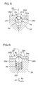
- the outer ring 28 comprises a main body 281 fitted in the fitting hole 25, and a closed end 282 provided at one end in the axial direction of the main body 281.
- a ball 30 is held in a ball holding hole 29 formed on an end surface 24a of the trunnion 24.
- a ball receiving section 31 for elastically receiving the ball 30 is formed on an inner surface 283 at the closed end 282 of the outer ring 28.
- the ball holding hole 29 comprises a circular hole arranged coaxially with the trunnion 24.
- the ball 30 is pressed into the ball holding hole 29 composed of the circular hole. That is, the ball 30 is held in the ball holding hole 29 with an interference.
- the movement of the ball 30 in the axial direction A1 and the radial direction R1 of the trunnion 24 is regulated.
- a part of the ball 30 projects toward the closed end 282 of the outer ring 28 from the ball holding hole 29. The part of the ball 30 is received by the ball receiving section 31.
- a center hole provided when the circular hole serving as the ball holding hole 29 is processed is formed so as to connect with an innermost portion of the ball holding hole 29.
- the ball receiving section 31 is composed of a conical tapered surface centered around a central axis C1 of the outer ring 28, and is brought into linear contact with the ball 30.
- a projection 32 swollen out so as to form the ball receiving section 31 on the inner surface 283 at the closed end 282 of the outer ring 28 is provided on an outer surface 284 at the closed end 282.
- An inward annular flange 33 is extended at the other end of the main body 281 in the outer ring 28.
- An annular oil seal 34 is held between the annular flange 33 and the shoulder of the trunnion 24.
- An area between the outer ring 28 and the trunnion 24 is liquid-tightly sealed by the oil seal 34.
- the present invention Since the ball 30 is pressed into the ball holding hole 29 composed of the circular hole, the present invention has the following advantages. That is, when the universal joint 4 is assembled, the amount of pressing of the ball 30 into the ball holding hole 29 by the outer ring 28 is automatically adjusted even if there are variations in tolerance among components in the axial direction A1 of the trunnion 24, so that the above-mentioned variations can be absorbed. Consequently, a load applied to the outer ring 28 from the ball 30 is not excessive, thereby making it possible to eliminate backlash in the axial direction A1 between the trunnion 24 and the outer ring 28 while restraining resistance torque at the time of rotation.
- the ball receiving section 31 is composed of a conical tapered surface
- the present invention is not limited to the same.
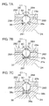
- a ball receiving section 31A composed of a concavely-curved surface having a larger radius of curvature Rb than the radius Ra of the ball 30 may be used, as shown in Fig. 5.
- the concavely-curved surface is a part of a spherical surface, for example.
- a ball holding hole 29A for holding the ball 30 so as to be slidable in the axial direction A1 of the trunnion 24 may be provided, as shown in Fig. 6.
- the ball 30 may be elastically urged toward the ball receiving section 31 by a helical compression spring 35 serving as an urging member accommodated in the ball holding hole 29A.
- the helical compression spring 35 is interposed between a bottom 291 of the ball holding hole 29A and the ball 30.
- the helical compression spring 35 may be replaced with a belleville spring 36, as shown in Fig. 7A, as an elastic member. An inner peripheral edge 36a of the belleville spring 36 is brought into contact with the ball 30.
- an urging member 37 may be used.
- the urging member 37 comprises a base 37a serving as a supporting section composed of an annular plate received by the bottom 291 of the ball holding hole 29A, and a belleville spring 37b extended so as to spread in a conical tapered shape from an inner peripheral edge of the base 37a.
- the belleville spring 37b has a conical tapered surface receiving the ball 30.
- the urging member 38 may be used.
- the urging member 38 comprises a disc-shaped base 38a received by the bottom 291 of the ball holding hole 29A, a cylinder 38b extended in an orthogonal shape from an outer peripheral edge of the base 38a, and a belleville spring 38c whose diameter is reduced in a conical tapered shape toward the bottom 291 of the ball holding hole 29A from one edge of the cylinder 38b.
- the belleville spring 38c has a conical tapered surface receiving the ball 30.
- the base 38a and the cylinder 38b constitute a supporting section for supporting the belleville spring 38c.
- the trunnion 24 does not produce backlash in the radial direction R1.
- the ball receiving section 31 Since the ball receiving section 31 is brought into linear contact with the ball 30, the rise in resistance torque can be restrained, as compared with that in a case where it is brought into surface contact with the ball 30. As a result, a universal joint 4 capable of reducing noise and having low resistance torque can be realized.
- Fig. 8 illustrates another embodiment of the present invention.
- the present embodiment is characterized in that an urging member 39 comprising a base 39a, a cylinder 39b, a projection for urging a ball (hereinafter referred to as a ball urging projection) 39c, and a projection for preventing a ball from slipping off (hereinafter referred to as a ball slip preventing projection) 39d is used.
- an urging member 39 comprising a base 39a, a cylinder 39b, a projection for urging a ball (hereinafter referred to as a ball urging projection) 39c, and a projection for preventing a ball from slipping off (hereinafter referred to as a ball slip preventing projection) 39d is used.
- the base 39a is composed of an annular plate received by the bottom 291 of a ball holding hole 29A.
- the cylinder 39b is extended in an orthogonal shape from an outer peripheral edge of the base 39a and is fitted in an inner peripheral surface of the ball holding hole 29A in a state where it surrounds a ball 30.
- the ball urging projection 39c projects in a mountain shape inward from a halfway portion in the axial direction of the cylinder 39b, the ball 30 is elastically urged toward the ball receiving section 31 (in an axial direction A1 of a trunnion 24), and the ball 30 is elastically urged in a radial direction R1 of the trunnion 24.
- the ball slip preventing projection 39d is formed so as to project in a mountain shape inward toward one end of the cylinder 39b, and is engaged with the ball 30 to prevent the ball 30 from slipping off the ball holding hole 29.
- the projections 39c and 39d may be formed on the whole periphery of the cylinder 39b. Alternatively, a plurality of projections may be formed with equal spacing in the circumferential direction.
- a universal joint 4 capable of reducing noise and having low resistance torque can be also realized, as in each of the embodiments shown in Figs. 7A to 7C.
- the ball 30 can be held within the cylinder 39b between the ball urging projection 39c and the ball slip preventing projection 39d. That is, the ball 30 can be held in the ball holding hole 29A using the urging member 39, thereby making it possible to improve workability at the time of assembling.
- the universal joint according to the present invention is not limited to a steering device.
- it is suitably applied as a universal joint in another rotating member, such as a propeller shaft of the automobile.
Applications Claiming Priority (2)
| Application Number | Priority Date | Filing Date | Title |
|---|---|---|---|
| JP2004244883A JP2006064020A (ja) | 2004-08-25 | 2004-08-25 | 自在継手 |
| PCT/JP2005/015474 WO2006022351A1 (fr) | 2004-08-25 | 2005-08-25 | Joint universel |
Publications (2)
| Publication Number | Publication Date |
|---|---|
| EP1783387A1 true EP1783387A1 (fr) | 2007-05-09 |
| EP1783387A4 EP1783387A4 (fr) | 2009-03-18 |
Family
ID=35967558
Family Applications (1)
| Application Number | Title | Priority Date | Filing Date |
|---|---|---|---|
| EP05774682A Withdrawn EP1783387A4 (fr) | 2004-08-25 | 2005-08-25 | Joint universel |
Country Status (6)
| Country | Link |
|---|---|
| US (1) | US20080248883A1 (fr) |
| EP (1) | EP1783387A4 (fr) |
| JP (1) | JP2006064020A (fr) |
| KR (1) | KR20070039871A (fr) |
| CN (1) | CN100497982C (fr) |
| WO (1) | WO2006022351A1 (fr) |
Cited By (4)
| Publication number | Priority date | Publication date | Assignee | Title |
|---|---|---|---|---|
| EP2393185A2 (fr) | 2010-06-04 | 2011-12-07 | Vestel Elektronik Sanayi ve Ticaret A.S. | Support basse consommation par système d'alimentation à distance ultrasonique |
| FR2966214A1 (fr) * | 2010-10-13 | 2012-04-20 | Skf Ab | Ensemble de liaison pour joint de transmission et joint de transmission associe. |
| EP2824344A3 (fr) * | 2013-06-18 | 2016-01-06 | Jtekt Corporation | Cuvette de roulement et joint d'arbre transversal |
| EP3315808A4 (fr) * | 2015-06-17 | 2019-07-10 | JTEKT Corporation | Procédé de fabrication d'un joint universel |
Families Citing this family (5)
| Publication number | Priority date | Publication date | Assignee | Title |
|---|---|---|---|---|
| JP2007255645A (ja) * | 2006-03-24 | 2007-10-04 | Jtekt Corp | 自在継手 |
| JP6707896B2 (ja) * | 2016-02-24 | 2020-06-10 | 株式会社ジェイテクト | 等速ジョイント |
| CN110043571A (zh) * | 2019-04-29 | 2019-07-23 | 万向钱潮股份有限公司 | 一种弹簧吸振式新型长寿命万向节 |
| CN110030288A (zh) * | 2019-04-29 | 2019-07-19 | 万向钱潮股份有限公司 | 一种可吸振长寿命万向节 |
| CN111677776B (zh) * | 2020-06-17 | 2021-09-14 | 宿迁学院 | 一种多级起动的无刷直流电机系统 |
Citations (3)
| Publication number | Priority date | Publication date | Assignee | Title |
|---|---|---|---|---|
| US1987415A (en) * | 1931-11-23 | 1935-01-08 | Joseph E Padgett | Method of making universal joints |
| GB842164A (en) * | 1957-06-17 | 1960-07-20 | Luciano Chierichetti | Improvements in or relating to articulated joints |
| JPH08135674A (ja) * | 1994-11-11 | 1996-05-31 | Nippon Seiko Kk | 自在継手 |
Family Cites Families (13)
| Publication number | Priority date | Publication date | Assignee | Title |
|---|---|---|---|---|
| US1943814A (en) * | 1933-08-09 | 1934-01-16 | Charles D Cutting Inc | Universal joint |
| US2063787A (en) * | 1934-09-24 | 1936-12-08 | Torrington Co | Antifriction bearing and method of making the same |
| US2727370A (en) * | 1950-04-05 | 1955-12-20 | Clifford Catesby Rogers | Universal couplings |
| JPS4612082Y1 (fr) * | 1968-02-27 | 1971-04-27 | ||
| DE2120569A1 (de) * | 1971-04-27 | 1972-11-02 | Volkswagenwerk Ag, 3180 Wolfsburg | Kreuzgelenk, insbesondere für die Gelenkwelle einer Fahrzeuglenkung |
| GB1480650A (en) * | 1973-08-23 | 1977-07-20 | Nadella & Pitner | Universal joints |
| JPH02180316A (ja) * | 1988-12-29 | 1990-07-13 | Nippon Seiko Kk | 自在継手 |
| DE19813114A1 (de) * | 1998-03-25 | 1999-09-30 | Schaeffler Waelzlager Ohg | Kreuzgelenk |
| JP2001065556A (ja) * | 1999-08-26 | 2001-03-16 | Minebea Co Ltd | ピボットアッセンブリー |
| JP2001193753A (ja) * | 2000-01-07 | 2001-07-17 | Koyo Seiko Co Ltd | 自在継手 |
| JP4219583B2 (ja) * | 2001-10-26 | 2009-02-04 | Ntn株式会社 | 固定型等速自在継手 |
| JP2004011670A (ja) * | 2002-06-03 | 2004-01-15 | Koyo Seiko Co Ltd | 十字軸用シール構造 |
| DE102005019692A1 (de) * | 2005-04-28 | 2006-11-23 | Schaeffler Kg | Gelenkkreuzbüchse mit Axialführung |
-
2004
- 2004-08-25 JP JP2004244883A patent/JP2006064020A/ja not_active Withdrawn
-
2005
- 2005-08-25 US US10/594,560 patent/US20080248883A1/en not_active Abandoned
- 2005-08-25 CN CNB2005800140561A patent/CN100497982C/zh not_active Expired - Fee Related
- 2005-08-25 EP EP05774682A patent/EP1783387A4/fr not_active Withdrawn
- 2005-08-25 WO PCT/JP2005/015474 patent/WO2006022351A1/fr active Application Filing
- 2005-08-25 KR KR1020067020565A patent/KR20070039871A/ko not_active Application Discontinuation
Patent Citations (3)
| Publication number | Priority date | Publication date | Assignee | Title |
|---|---|---|---|---|
| US1987415A (en) * | 1931-11-23 | 1935-01-08 | Joseph E Padgett | Method of making universal joints |
| GB842164A (en) * | 1957-06-17 | 1960-07-20 | Luciano Chierichetti | Improvements in or relating to articulated joints |
| JPH08135674A (ja) * | 1994-11-11 | 1996-05-31 | Nippon Seiko Kk | 自在継手 |
Non-Patent Citations (1)
| Title |
|---|
| See also references of WO2006022351A1 * |
Cited By (6)
| Publication number | Priority date | Publication date | Assignee | Title |
|---|---|---|---|---|
| EP2393185A2 (fr) | 2010-06-04 | 2011-12-07 | Vestel Elektronik Sanayi ve Ticaret A.S. | Support basse consommation par système d'alimentation à distance ultrasonique |
| FR2966214A1 (fr) * | 2010-10-13 | 2012-04-20 | Skf Ab | Ensemble de liaison pour joint de transmission et joint de transmission associe. |
| EP2824344A3 (fr) * | 2013-06-18 | 2016-01-06 | Jtekt Corporation | Cuvette de roulement et joint d'arbre transversal |
| US9404530B2 (en) | 2013-06-18 | 2016-08-02 | Jtekt Corporation | Bearing cup and cross shaft joint |
| EP3315808A4 (fr) * | 2015-06-17 | 2019-07-10 | JTEKT Corporation | Procédé de fabrication d'un joint universel |
| US10399188B2 (en) | 2015-06-17 | 2019-09-03 | Jtekt Corporation | Method for manufacturing universal joint |
Also Published As
| Publication number | Publication date |
|---|---|
| KR20070039871A (ko) | 2007-04-13 |
| CN1950620A (zh) | 2007-04-18 |
| US20080248883A1 (en) | 2008-10-09 |
| JP2006064020A (ja) | 2006-03-09 |
| EP1783387A4 (fr) | 2009-03-18 |
| CN100497982C (zh) | 2009-06-10 |
| WO2006022351A1 (fr) | 2006-03-02 |
Similar Documents
| Publication | Publication Date | Title |
|---|---|---|
| EP1783387A1 (fr) | Joint universel | |
| CA1212266A (fr) | Ensemble a pivot | |
| CN111356599B (zh) | 伸缩连杆和悬架 | |
| EP1908974A1 (fr) | Arbre telescopique et dispositif de direction pour vehicule | |
| JPH09196083A (ja) | カルダン軸に対する自在継手装置 | |
| CN114131311A (zh) | 一种同轴度调节装置、蜗轮蜗杆转向机及装配装置 | |
| JP4245849B2 (ja) | プロペラシャフト用等速自在継手 | |
| JP4773233B2 (ja) | 自在継手 | |
| JP2001099218A (ja) | ストラットマウント | |
| CN113167332A (zh) | 用于机动车辆的转向轴的万向接头 | |
| US7476156B2 (en) | Homokinetic joint | |
| KR101017269B1 (ko) | 자동차용 조향축의 유니버셜 조인트 | |
| JP2000170786A (ja) | 軸継手 | |
| JP2007120667A (ja) | トリポード型等速自在継手 | |
| JP2006298297A (ja) | ステアリング用等速自在継手 | |
| JP5607463B2 (ja) | 電動パワーステアリング装置 | |
| JP2899975B2 (ja) | ねじり緩衝装置 | |
| JP3446541B2 (ja) | ダブルカルダン式等速ジョイント | |
| JP6512387B1 (ja) | 伸縮リンク及びサスペンション | |
| JPH09324823A (ja) | ダブルカルダン式等速ジョイント | |
| JP2006083930A (ja) | 自在継手 | |
| JP2003287053A (ja) | ステアリング装置用自在継手 | |
| JPH0738736Y2 (ja) | センタリングブッシュ | |
| US20220065305A1 (en) | Torque transmission device with springs in series and torque transmission system comprising such a device | |
| JPH0972348A (ja) | ユニバーサルジョイント |
Legal Events
| Date | Code | Title | Description |
|---|---|---|---|
| PUAI | Public reference made under article 153(3) epc to a published international application that has entered the european phase |
Free format text: ORIGINAL CODE: 0009012 |
|
| 17P | Request for examination filed |
Effective date: 20061104 |
|
| AK | Designated contracting states |
Kind code of ref document: A1 Designated state(s): CZ DE FR GB |
|
| DAX | Request for extension of the european patent (deleted) | ||
| RBV | Designated contracting states (corrected) |
Designated state(s): CZ DE FR GB |
|
| A4 | Supplementary search report drawn up and despatched |
Effective date: 20090217 |
|
| STAA | Information on the status of an ep patent application or granted ep patent |
Free format text: STATUS: THE APPLICATION HAS BEEN WITHDRAWN |
|
| 18W | Application withdrawn |
Effective date: 20090630 |