EP1783075A2 - Gummiroller und damit ausgerüstete Papierbogenentnahmevorrichtung - Google Patents
Gummiroller und damit ausgerüstete Papierbogenentnahmevorrichtung Download PDFInfo
- Publication number
- EP1783075A2 EP1783075A2 EP06021626A EP06021626A EP1783075A2 EP 1783075 A2 EP1783075 A2 EP 1783075A2 EP 06021626 A EP06021626 A EP 06021626A EP 06021626 A EP06021626 A EP 06021626A EP 1783075 A2 EP1783075 A2 EP 1783075A2
- Authority
- EP
- European Patent Office
- Prior art keywords
- paper sheet
- roller
- take
- outer layer
- inner layer
- Prior art date
- Legal status (The legal status is an assumption and is not a legal conclusion. Google has not performed a legal analysis and makes no representation as to the accuracy of the status listed.)
- Pending
Links
- 229920001971 elastomer Polymers 0.000 title claims abstract description 132
- 239000000463 material Substances 0.000 claims abstract description 33
- 238000000926 separation method Methods 0.000 claims description 39
- 230000004888 barrier function Effects 0.000 claims description 20
- 238000012546 transfer Methods 0.000 claims description 14
- 230000007246 mechanism Effects 0.000 claims description 13
- 239000004014 plasticizer Substances 0.000 claims description 11
- -1 polyethylene Polymers 0.000 claims description 9
- 239000004698 Polyethylene Substances 0.000 claims description 8
- 239000004743 Polypropylene Substances 0.000 claims description 8
- 229920005989 resin Polymers 0.000 claims description 8
- 239000011347 resin Substances 0.000 claims description 8
- 229920000573 polyethylene Polymers 0.000 claims description 7
- 229920001155 polypropylene Polymers 0.000 claims description 7
- 230000002441 reversible effect Effects 0.000 claims description 6
- VGGSQFUCUMXWEO-UHFFFAOYSA-N Ethene Chemical compound C=C VGGSQFUCUMXWEO-UHFFFAOYSA-N 0.000 claims description 4
- 239000005977 Ethylene Substances 0.000 claims description 4
- 239000004810 polytetrafluoroethylene Substances 0.000 claims description 4
- 229920001343 polytetrafluoroethylene Polymers 0.000 claims description 4
- 230000000149 penetrating effect Effects 0.000 claims 2
- 229920001875 Ebonite Polymers 0.000 abstract description 2
- 230000004048 modification Effects 0.000 description 9
- 238000012986 modification Methods 0.000 description 9
- FLKPEMZONWLCSK-UHFFFAOYSA-N diethyl phthalate Chemical compound CCOC(=O)C1=CC=CC=C1C(=O)OCC FLKPEMZONWLCSK-UHFFFAOYSA-N 0.000 description 8
- 230000003247 decreasing effect Effects 0.000 description 7
- 230000007423 decrease Effects 0.000 description 5
- 238000003780 insertion Methods 0.000 description 5
- 230000037431 insertion Effects 0.000 description 5
- 230000035939 shock Effects 0.000 description 5
- ZFMQKOWCDKKBIF-UHFFFAOYSA-N bis(3,5-difluorophenyl)phosphane Chemical compound FC1=CC(F)=CC(PC=2C=C(F)C=C(F)C=2)=C1 ZFMQKOWCDKKBIF-UHFFFAOYSA-N 0.000 description 4
- 229920002943 EPDM rubber Polymers 0.000 description 3
- 239000006229 carbon black Substances 0.000 description 3
- 230000000694 effects Effects 0.000 description 3
- 238000004519 manufacturing process Methods 0.000 description 3
- 238000003825 pressing Methods 0.000 description 3
- 244000043261 Hevea brasiliensis Species 0.000 description 2
- 238000005452 bending Methods 0.000 description 2
- 238000006243 chemical reaction Methods 0.000 description 2
- 230000006835 compression Effects 0.000 description 2
- 238000007906 compression Methods 0.000 description 2
- 229920003052 natural elastomer Polymers 0.000 description 2
- 229920001194 natural rubber Polymers 0.000 description 2
- 230000036961 partial effect Effects 0.000 description 2
- 238000011144 upstream manufacturing Methods 0.000 description 2
- 229920006311 Urethane elastomer Polymers 0.000 description 1
- 229920005549 butyl rubber Polymers 0.000 description 1
- 230000015556 catabolic process Effects 0.000 description 1
- 238000006731 degradation reaction Methods 0.000 description 1
- 238000004925 denaturation Methods 0.000 description 1
- 230000036425 denaturation Effects 0.000 description 1
- 238000001514 detection method Methods 0.000 description 1
- 239000013013 elastic material Substances 0.000 description 1
- 230000035553 feeding performance Effects 0.000 description 1
- 239000002184 metal Substances 0.000 description 1
- 238000000034 method Methods 0.000 description 1
- 238000012544 monitoring process Methods 0.000 description 1
- 238000000465 moulding Methods 0.000 description 1
- 230000002093 peripheral effect Effects 0.000 description 1
- 230000008569 process Effects 0.000 description 1
- 230000002829 reductive effect Effects 0.000 description 1
- 239000007787 solid Substances 0.000 description 1
- 230000003068 static effect Effects 0.000 description 1
Images




Classifications
-
- B—PERFORMING OPERATIONS; TRANSPORTING
- B65—CONVEYING; PACKING; STORING; HANDLING THIN OR FILAMENTARY MATERIAL
- B65H—HANDLING THIN OR FILAMENTARY MATERIAL, e.g. SHEETS, WEBS, CABLES
- B65H3/00—Separating articles from piles
- B65H3/02—Separating articles from piles using friction forces between articles and separator
- B65H3/06—Rollers or like rotary separators
-
- B—PERFORMING OPERATIONS; TRANSPORTING
- B65—CONVEYING; PACKING; STORING; HANDLING THIN OR FILAMENTARY MATERIAL
- B65H—HANDLING THIN OR FILAMENTARY MATERIAL, e.g. SHEETS, WEBS, CABLES
- B65H3/00—Separating articles from piles
- B65H3/02—Separating articles from piles using friction forces between articles and separator
- B65H3/06—Rollers or like rotary separators
- B65H3/0638—Construction of the rollers or like rotary separators
-
- B—PERFORMING OPERATIONS; TRANSPORTING
- B65—CONVEYING; PACKING; STORING; HANDLING THIN OR FILAMENTARY MATERIAL
- B65H—HANDLING THIN OR FILAMENTARY MATERIAL, e.g. SHEETS, WEBS, CABLES
- B65H3/00—Separating articles from piles
- B65H3/02—Separating articles from piles using friction forces between articles and separator
-
- B—PERFORMING OPERATIONS; TRANSPORTING
- B65—CONVEYING; PACKING; STORING; HANDLING THIN OR FILAMENTARY MATERIAL
- B65H—HANDLING THIN OR FILAMENTARY MATERIAL, e.g. SHEETS, WEBS, CABLES
- B65H3/00—Separating articles from piles
- B65H3/02—Separating articles from piles using friction forces between articles and separator
- B65H3/06—Rollers or like rotary separators
- B65H3/0653—Rollers or like rotary separators for separating substantially vertically stacked articles
-
- B—PERFORMING OPERATIONS; TRANSPORTING
- B65—CONVEYING; PACKING; STORING; HANDLING THIN OR FILAMENTARY MATERIAL
- B65H—HANDLING THIN OR FILAMENTARY MATERIAL, e.g. SHEETS, WEBS, CABLES
- B65H2220/00—Function indicators
- B65H2220/09—Function indicators indicating that several of an entity are present
-
- B—PERFORMING OPERATIONS; TRANSPORTING
- B65—CONVEYING; PACKING; STORING; HANDLING THIN OR FILAMENTARY MATERIAL
- B65H—HANDLING THIN OR FILAMENTARY MATERIAL, e.g. SHEETS, WEBS, CABLES
- B65H2401/00—Materials used for the handling apparatus or parts thereof; Properties thereof
- B65H2401/10—Materials
- B65H2401/11—Polymer compositions
- B65H2401/111—Elastomer
-
- B—PERFORMING OPERATIONS; TRANSPORTING
- B65—CONVEYING; PACKING; STORING; HANDLING THIN OR FILAMENTARY MATERIAL
- B65H—HANDLING THIN OR FILAMENTARY MATERIAL, e.g. SHEETS, WEBS, CABLES
- B65H2701/00—Handled material; Storage means
- B65H2701/10—Handled articles or webs
- B65H2701/19—Specific article or web
- B65H2701/1916—Envelopes and articles of mail
Definitions
- the present invention relates to a rubber roller to contact and rotates with a paper sheet, and a paper sheet take-out device including the rubber roller.
- This take-out apparatus has a stacker to house paper sheets stacked upright, a take-out roller pressed to contact a paper sheet at one end of the stacking direction of the paper sheets housed in the stacker, and a separation unit which separates paper sheets doubly taken out by receiving and passing the taken-out paper sheets through a nip (e.g., Jpn. Pat. Appln. KOKAI Publication No. 2003-341860 ).
- a nip e.g., Jpn. Pat. Appln. KOKAI Publication No. 2003-341860 .
- the take-out roller rotates and contacts a paper sheet at one end of the stacking direction, and takes out the paper sheet by the frictional force generated between the peripheral surface and the paper sheet surface. At this time, if the paper sheet at one end of the stacking direction is inclined when contacting the take-out roller, the take-out roller rotates by contacting the paper sheet at the edge, and insufficient frictional force is applied to the paper sheet. If the rotation of the take-out roller is continued with the edge contacting the paper sheet, the take-out roller will be unevenly worn, the edge of the roller will become round, and the contact area of the take-out roller to an upright paper sheet will become smaller.
- a rubber roller according to an embodiment of the invention rotates by contacting a paper sheet, has an outer layer made of rubber material of JIS-A with a hardness over 35 Ha and below 90 Ha, and an inner layer provided inside the outer layer and made of non-foamed rubber material of JIS-A with a hardness over 5 Ha and below 25 Ha.
- the hardness of the outer layer is set to over JIS-A 35 Ha and below 90 Ha to ensure a sufficient wear proof
- the inner layer hardness is set soft over JIS-A 5 Ha and below 25 Ha. Therefore, the rubber roller is configured to make contact with a paper sheet stably and sufficiently widely by deforming the inner surface according to the state (e.g., inclination) of a paper sheet to make contact with the outer surface, and a sufficient friction force is applied to the paper sheet surface irrespectively of the state of the paper sheet.
- This eliminates the necessity of a mechanism to move the rubber roller according to the changes in the state of the paper sheet simplifies the structure of the apparatus, reduces the manufacturing cost of the apparatus, and reduces the size of the apparatus.
- the periphery of the roller stably contacts a paper sheet, and the edge of the outer layer does not contact a paper sheet and is not unevenly worn, and a decrease in the frictional force with time is prevented.
- a rubber roller according to an embodiment of the invention has a substantially cylindrical roller body which is made of rubber material, has an outer surface to contact a paper sheet, and a remover which is made soft by partially removing the roller body, to make the outer surface sufficiently contact a paper sheet by deforming the roller body to meet the state of a paper sheet to contact.
- the roller body is made soft in an area of the remover, the roller body is easily deformed to meet the state (e.g., inclination) of the paper sheet contacting the outer surface, and the outer surface of the roller contacts the paper sheet stably and sufficiently widely.
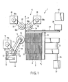
- FIG. 1 is a top plane view showing the structure of a paper sheet take-out apparatus 1 (hereinafter simply called a take-out apparatus) according to an embodiment of the invention.
- FIG. 2 a front view of the take-out apparatus 1 of FIG. 1, viewed from the upstream side of a direction of taking out paper sheets P.
- FIG. 3 is a side view of the take-out apparatus 1 viewed from a direction of stacking paper sheets P.
- the take-out apparatus 1 has a stacker 2 which houses the paper sheets P such as mail stacked upright, a take-out roller 4 (a rubber roller) which contacts and rotates with the paper sheet P1 supplied to a take-out position at one end of a stacking direction (the left end in the drawing), and takes out the paper sheet P1 in the substantially horizontal direction substantially orthogonal to the stacking direction (in the direction of the arrow T in the drawing), a floor belt 6 which is extended movably along the paper sheets P stacking direction in the state contacting the lower end sides of all paper sheets P housed in the stacker 2, a backup plate 8 which is provided movably in the stacking direction in the state facing closely to the upper end of the paper sheet P2 at the other end of the stacking direction (at the right end in the drawing) remote from the floor belt 6, and a separation unit 10 (a separation mechanism) which separates the paper sheets P taken out by the take-out roller 24 one by one, and feed the paper sheet to a processor in a later state.
- the take-out roller 4 has a lower roller 4L to contact the paper sheet P1 at one end of the stacking direction in the area close to the lower end, and an upper roller 4U to contact the paper sheet P1 in the area close to the upper end.
- the lower roller 4L and upper roller 4U are provided rotatably along the predetermined direction about a rotation axis 5 (refer to FIG. 1) extended in a substantially vertical direction, that is, the direction of taking out the paper sheet P1 (in the direction of the arrow T in FIG. 1) .
- the rotation axis 5 of the rollers 4L and 4U is pivotally fixed to the distal ends of arms 11L and 11U.
- the proximal ends of the arms 11L and 11U are pivotally fixed to a not-shown casing of the take-out apparatus 1. Therefore, when the arms 11L and 11U are driven by motors 14L and 14U (refer to FIG. 3) described later, the rollers 4L and 4U contact and separate from the paper sheet P1 at one end of the stacking direction.
- sensors 12L and 12U are provided to detect the positions of the rollers 4L and 4U contacting the paper sheet P1, or the positions XL and XU of the rollers 4L and 4U along the stacking direction rotationally contacting the paper sheet P1 at one end of the stacking direction, by detecting the rotational angles of the arm 11.
- motors 14L and 14U are provided to swing the arms 11L and 11U through link mechanisms 13L and 13U (refer to FIG. 3) are connected.
- the arms 11L/11U, link mechanisms 13L/13U and motors 14L/14U move the rollers 4L and 4U in the direction of stacking the paper sheet P.
- sensors 15L and 15U are provided at the middle of the link mechanisms 13L and 13U to detect the pressures of FL and FU of the rollers 4L and 4U contacting the paper sheet P1.
- the sensor 15L detects the contact pressure FL of the lower roller 4L to the paper sheet P1
- the sensor 15U detects the contact pressure FU of the upper roller 4U to the paper sheet P1.
- the rollers 4L and 4U are brought into contact with the paper sheet P1 at a desired contact pressure, by driving the motors 14L and 14U by monitoring the outputs of the sensors 15L and 15U.
- two pulleys 16 and 17 are provided as one unit rotatably and coaxially with the rotational axis of the arm 11.
- An endless belt 18 wound on a pulley 4a provided on the rotation axis 5 of the rollers 4L/4U is wound on the pulley 16.
- An endless belt 20 wound on a pulley 19a provided on the rotation axis of the motor 19 to simultaneously rotate the rollers 4L and 4L is provided on the other pulley 17. Therefore, the lower roller 4L and upper roller 4U are rotated in a predetermined direction at a desired speed by driving the motor 19.
- the floor belt 6 has two endless belts extended over along the paper sheet P stacking direction in the front and rear sides of the apparatus.
- a motor 22 for driving the floor belt 6 in the forward and rearward directions along the stacking direction is provided on the rotation axis 6a of the roller (not shown) on which the belts are wound.
- the backup plate 8 is provided slidably with respect to a rail 24 extended in the stacking direction, at a position close to the upper end of the paper sheet stack, in the rear side of the stacker 2 and remote from the floor belt 6.
- the backup plate 8 is provided at a position opposite to the upper end of the paper sheet P2 housed upright in the stacker 2 at the other end of the stacking direction.
- the backup plate 8 is moved in the stacking direction along the rail 24, by a motor 26 connected through a not-shown driving mechanism.
- the floor belt 6 driven by the motor 22 and the backup plate 8 driven by the motor 26 functions as a supply mechanism of the invention, which cooperates and moves the paper sheets stacker in the stacker 2 in the stacking direction, and supplies the paper sheet P1 at one end of the stacking direction to the take-out position.
- the take-out apparatus 1 As the take-out roller 4 takes out the stacked paper sheet to the conveying path sequentially from the paper sheet P1 stacked at one end of the stacking direction, the floor belt 6 is driven whenever the paper sheet P is taken out, and the backup plate 8 is moved. In other words, the floor belt 6 and backup plate 8 are driven, so that the paper sheet P1 at one end of the stacking direction is always supplied to the take-out position.
- the separation unit 10 has a feed roller 32 provided at a position rotationally contacting one side (the left side in FIG. 1) of the paper sheet P taken out in the direction of the arrow T by the take-out roller 4, and a separation roller 34 (rubber roller) provided opposite to the feed roller 32 with a predetermined gap through the paper sheet conveying path.
- the separation unit 10 has a motor 36 to rotate the feed roller 32 in the paper sheet feeding direction (forward), and a motor 38 to impart a reverse torque to the separation roller 34.
- An endless belt 33 is extended over a pulley 36a provided on the rotation axis of a motor 36 and a pulley 32a provided on the rotation axis of the feed roller 32.
- An endless belt 35 is extended over a pulley 38a provided on the rotation axis of a motor 38 and a pulley 34a provided on the rotation axis of a separation roller 34. Therefore, the feed roller is rotated forward by the motor 36, and a reverse separation torque is imparted to the separation roller 34 by the motor 38.
- the take-out apparatus 1 has a control unit 40, which monitors the outputs of the sensors 12L, 12U, 15L and 15U, and controls the driving of the motors 14L, 14U, 19, 22, 26, 36, and 38.
- the control unit 40 controls the motors 14L and 14U, and adjusts the contact pressures FL and FU of the upper and lower rollers 4U and 4L to optimum values, based on the detection results of the sensors 15L and 15U.
- the control unit 40 controls the motors 22 and 26, moves the floor belt 6 and/or backup plate 8, and adjusts the contact pressures FL and FU of the upper roller 4U and/or lower roller 4L to optimum values.
- the take-out apparatus 1 collectively inputs and processes several kinds of paper sheets P such as mail with different size and thickness, after several numbers of paper sheets P are stacked and set in the stacker 2, the paper sheet P1 stacked at one end of the stacking direction is rarely supplied in a state upright to the outer surface of the take-out roller 4.
- the upper roller 4U contacts the area close to the upper end of the paper sheet P1 stacked at one end of the stacking direction, but the lower roller 4L does not contact the paper sheet P. If the paper sheet P is continuously taken out in this state, the corner of the upper roller 4U contacting the paper sheet P is partially worn.
- the inclination angle of the paper sheet P with a different size is not constant, and the corner of the upper roller is rounded as shown in FIG. 4 when the wear advances.
- the frictional force decrease caused by the partial wear of the take-out roller 4 gradually advances from the initial state of the roller, and the frictional force is gradually decreased from immediately after the start of using the roller. To prevent the decrease of the frictional force, it is considerable to gradually increase the contact pressure of the take-out roller 4 to the paper sheet P. However, if the contact pressure of the take-out roller 4 is increased, there arises another problem of mis-feeding of several paper sheets P.
- the partial wear of the take-out roller 4 reduces the life of the roller in a very short time.
- the take-out roller 4 even if the paper sheet P is supplied to the take-out position in the inclined state, the take-out roller 4 follows the inclination of the paper sheet P and changes the form, and the outer surface of the take-out roller 4 is brought into contact with the surface of the paper sheet P in a sufficient area, without increasing the contact pressure to the paper sheet P.
- an explanation will be given on the take-out roller 4 according to a first embodiment of the invention with reference to FIG. 6.
- the take-out roller 4 has an outer layer 42 made of relatively hard rubber having a sufficient coefficient of kinetic friction to the surface of the paper sheet P to contact and being sufficiently wearproof, and an inner layer 44 provided inside the outer layer 42 and made of relatively soft rubber deformable by a weak force.
- the take-out roller 4 of this embodiment is formed by bonding the inner layer 44 to the outer surface of a core member 41, and bonding the outer layer 42 to the outer surface of the inner layer 44 through a barrier layer 46 shown partially enlarged in FIG. 7.
- the outer layer 42 of the take-out roller 4 is made of natural rubber, EPDM rubber or urethane rubber of JISK 6253 type A (JIS-A) having the coefficient of kinetic friction 1.0-1.5 to the surface of copy paper or envelope to contact, and the hardness of 35-90 Ha.
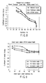
- FIG.8 is a graph showing the relation between the hardness of the rubber of the outer layer 42 and the coefficient of kinetic friction to an envelope.
- the pressing load of the take-out roller 4 is 100 g
- the relative sliding speed of the roller surface to an envelope is 1 m/s. It is seen from the graph that as the rubber roller hardness increases, the coefficient of kinetic friction decreases.
- the hardness of the outer layer 42 is lower than 35 Ha, the wear proof of the rubber roller is largely decreased and the life of the roller is reduced. Contrarily, if the hardness of the outer layer 42 is higher than 90 Ha, the coefficient of kinetic friction of the rubber roller is rapidly decreased to be lower than the coefficient of static friction between envelopes (approximately 0.4 Ha), and an envelope cannot be taken out. Namely, by setting the hardness of the outer layer 42 to over 35 Ha and below 90 Ha, the wearproof characteristic sufficient to take out the paper sheet P can be ensured, and the coefficient of kinetic friction necessary to take out an envelope can be ensured.
- the inner layer 44 is made of rubber material of JIS-A with the hardness of 5-25 Ha, such as butyl rubber or EPDM rubber.
- FIG. 9 is a graph showing the relationship between the coefficient of kinetic friction and the hardness of the inner layer 44 of the take-out roller 4 whose outer layer 42 is made of EPDM rubber with the hardness of 60 Ha, by taking the inclination angle of the paper sheet P to the take-out roller 4 as a parameter. It is seen from the graph that when the hardness of the inner layer 44 is set to over 5 Ha and below 25 Ha, a sufficiently large coefficient of kinetic friction can be obtained at each inclination angle.
- the hardness of the inner layer 44 is lower than 5 Ha, the rubber strength becomes insufficient, the rotation force of the axis is not transmitted to the rubber roller, and the roller is broken. Contrarily, if the hardness of the inner layer 44 is higher than 5 Ha, the rubber roller is insufficiently deformed at each inclination angle of an envelope, the coefficient of kinetic friction is not sufficiently increased, and the roller is partially worn. In other words, by setting the hardness of the inner layer 44 to over 5 Ha and below 25 Ha, the outer surface of the outer layer 42 stably contacts the paper sheet P inclined at various angles, and a sufficiently large frictional force can be applied to the paper sheet.
- the inner layer 44 bonded to the outer surface of the metal bar 41 may be made of other elastic materials such as a sponge and gel, but a stress may be generated in the clearance to the core member 41 by the rotation of roller, and the rubber roller may be broken. Therefore, it is necessary to use a non-foamed rubber for the inner layer 44.
- the barrier layer 46 shown partially enlarged in FIG. 7 is provided to prevent transfer of a plasticizer between the inner layer 44 and outer layer 42.
- the barrier layer is made of material whose index of solubility (SP value) of a transfer component is largely different from the SP values of the plasticizer of the inner layer 44 and outer layer 42. Namely, when different kinds of rubber contact for a relatively long time, it is known that a plasticizer is mainly transferred between the different kinds of rubber. Such a transfer of component occurs easily when the index of solubility of a transfer component is closer to that of a rubber.
- a plasticizer such as dioctyl adipate (DOA) and diethyl phthalate (DEP) is transferred from the relatively soft inner layer 44 to the outer layer 42, and the outer layer 42 may be denatured.
- the SP value of a plasticizer of the inner layer 44 such as dioctyl adipate (DOA) and diethyl phthalate (DEP)
- the barrier layer 46 is desirably made of resin such as ethylene resin terafluoride (PTFE, SP value 7.3), polyethylene (PE, SP value 7.9) and polypropylene (PP, SP value 7.9).
- the barrier layer 46 is made of rubber having an index of solubility lower than at least that of the component transferred from the inner layer 44 to the outer layer 42 and that of the component transferred from the outer layer 42 to the inner layer. This prevents denaturation of the inner layer 44 or outer layer 42 caused by the transfer of plasticizer, and prevents degradation of the characteristics of the take-out roller 4.
- the outer surface of the outer layer 42 stably contacts the surface of the paper sheet P as shown in FIG. 6, and a sufficient frictional force can be acted on the paper sheet.
- FIG. 10 is a sectional view of the take-out roller 50 according to a second embodiment of the invention.
- the take-out roller 50 has a relatively hard outer layer 52 made of the same rubber as the outer layer 42 of the take-out roller 4 of the first embodiment, and has an inner layer 54 made of rubber at least softer then the outer layer 52, inside the outer layer.
- a barrier layer (not shown) is provided between the outer layer 52 and inner layer 54, to prevent transfer of components such as a plasticizer.
- the hardness of the inner layer 54 is not strictly limited.
- the take-out roller 50 of this embodiment is characterized by a circular groove 56 (remover) formed in the inner layer.
- the circular groove 56 concentric with the rotational axis is formed by partially eliminating both end-faces in the axial direction of the inner layer 54 softer than the outer layer 52.
- the groove 56 functions to positively deform the inner layer 54 at the position of the groove 56, and to bring the outer surface of the outer layer 52 into contact with the surface of the paper sheet P stably and in a relatively wide area.
- the depth and width of the groove 56 determine the softness of the inner layer 54, and can be set to the values to achieve desired softness.
- the shape of the groove 56 is not limited to circular, and can be optionally changed according to the desired softness of the inner layer 54.
- the cross section of the groove 56 is desirably wide at the bottom, and desirably curved like an arc.
- the inner layer 54 may be made of rubber material with much carbon black added to natural rubber. This can increase the fatigue strength of the inner layer 54 and prevent the breakage of the inner layer, even if the groove 56 is formed in the inner layer.
- the outer layer 52 is made of rubber material with carbon black added, a black mark may be formed on the surface of the paper sheet P when touched by the take-out roller 50. However, it is no problem to add carbon black to the rubber material of the inner layer 54, which does not come in contact with the paper sheet P.
- FIG. 11 shows a modification of the take-out roller 50.
- This take-out roller 50' has the same structure as the take-out roller 50 of the second embodiment, except that the outer layer and inner layer are made of the same rubber material.
- the rubber material is selected by giving priority to the hardness of the outer layer and the coefficient of kinetic friction of the outer surface of the roller to the paper sheet P. Therefore, it is necessary to make the depth and width of the groove 56 relatively large to deform the roller following the state of the paper sheet P.
- this embodiment uses rubber material of JIS-A with the hardness of 35-90 Ha.
- FIG. 11 shows the state that one groove 56 is formed at the end-face of the axial direction of the roller. It is permitted to form a plurality of grooves substantially concentrically at each end-face.
- the softness of the roller capable of following the state of the paper sheet P can be achieved.
- the above-mentioned barrier layer becomes unnecessary.
- the inner layer 54 is deformed at the position of the groove 56 and the outer surface of the outer layer 52 contacts the surface of the paper sheet P stably in a sufficiently wide area.
- the rubber roller 60 of this embodiment can be used as the take-our roller 4 to take out the paper sheet P supplied to the take-out position in the direction of the surface crossing the stacking direction, and can also be used as the separation roller 34 of the separation unit 10 which separates the paper sheets P taken out in the stacked state into each single sheet.
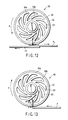
- the rubber roller 60 has basically the same structure as the take-out roller 4 of the first embodiment, except the slits 66 (remover) cut through the inner layer 64 in the axial direction.
- an outer layer 62 of the rubber roller 60 is made of the same rubber material as the outer layer 42 of the take-out roller 4 of the first embodiment.
- the hardness of the inner layer 64 may be at least softer than the outer layer 62, and may not be the same material as the inner layer 44 of the take-out roller 4 of the first embodiment.
- the same layer (not shown) as the above-mentioned barrier layer 46 is provided between the inner layer 62 and outer layer 64, when necessary.
- the slits 66 are formed symmetrically with respect to the rotation axis of the rubber roller 60, and extended and arranged spirally in the direction crossing the radial direction, so that the adjacent slits 66 are at least partially overlapped in the radial direction of the roller.
- a relatively thin cylindrical wall 64a contacting the outer layer 62 is formed in the inner layer 64 of the rubber roller 60, and relatively thin walls 64b with substantially the even thickness are formed between the adjacent slits 66.
- the walls 64b are extended radially and spirally in the direction crossing the radial direction from the rotation axis of the roller to the wall 64a.
- the inner layer 64 is easily deformed elastically.
- the walls 64a and 64b extending along substantially the periphery of the rubber roller (in the direction crossing the radial direction) can be formed, and the hardness of the rubber roller 60 along the radial direction can be made soft.
- a substantially bending stress not an compression stress to press the rubber roller 60 in the radial direction, acts on the walls 64a and 64b shaped as shown in the drawing, and the roller is easily deformed elastically against the load in the radial direction.
- the quantity and size of the slits 66 are selectable according to a desired hardness of the inner layer 64, and not limited to those shown in the drawing.
- this rubber roller 60 When this rubber roller 60 is used as a take-out roller, the inner layer 64 is elastically deformed by a relatively weak force as in the first and second embodiments, and the outer layer 62 of the rubber roller 60 can stably contact the paper sheet P supplied to the take-out position in the inclined state, and a sufficient frictional force is applied to the paper sheet P.
- the rubber roller 60 When the rubber roller 60 is used as the separation roller 34 of the separation unit 10, if the paper sheet P is inserted into the nip between the feed roller 32 and separation roller 34, the inner layer 64 is elastically deformed and absorbs the shock of the insertion. Compared with a case that the rubber roller 60 is pressed to the feed roller 32 by using a pinch, the rubber roller 60 does not jump up in the direction of separating from the feed roller 32, and the outer surface of the outer layer 62 can stably contact the surface of the paper sheet P passing through the nip.
- the separation roller 34 e.g., a solid rubber roller of the separation unit 10 to the feed roller 32 by using a spring
- the separation roller 34 jumps up in the direction of separating from the roller 32 and bounces several times.
- the separation roller 34 does not momentarily contact the paper sheet P passing through the nip. Namely, when stacked several paper sheets P are inserted into the nip, while the separation roller 34 is bouncing, the separation roller 34 does not impart a reverse separation torque to the second and following paper sheets, and these paper sheets are fed together with the first paper sheet, causing a double-feed.
- the rubber roller 60 of this embodiment when used as a separation roller, a mechanism to press the rubber roller 60 to the feed roller by a pinch becomes unnecessary, and even if stacked several paper sheets P are inserted into the nip, the inner layer 64 is deformed and absorbs the shock of the insertion, as described above, the periphery of the outer layer 62 stably contacts the second and following paper sheets P, and a reverse separation torque is stably imparted to the second and following paper sheets P. Namely, by using the rubber roller 60 of this embodiment, the probability of doubly feeding the paper sheet P can be drastically decreased.
- the rubber roller 60 of this embodiment can be used as a separation roller, and increases the paper sheet P feeding performance and the paper sheet P separation performance.
- the roller 60 is provided in the take-out apparatus 1 at the position to rotate in the direction of the arrow e (the position shown in FIGS. 12 and 13) when the paper sheet P is fed in the direction indicated by the arrow in FIG. 13 (in the left-hand direction).
- a frictional force f of the paper sheet P acts on the outer surface of the outer layer 62, as shown in FIG. 13.
- a resultant force h of the frictional force f and a reaction force g of the paper sheet P to the pressing force of the rubber roller 60 acts on the inner layer 64 of the rubber roller 60, as shown in the drawing.
- the resultant force h acts as a bending stress on the walls 64a and 64b of the inner layer 64, and the inner layer 64 is largely deformed by a relatively small force. Therefore, the shock of the insertion of the paper sheet P is absorbed, and the surface of the outer layer 62 contacts the paper sheet P stably in a sufficiently wide area.
- the rubber roller 60 rotates as a separation roller in the direction of the arrow a (in the reverse direction) to impart a separation torque.
- the rubber roller 60 applies a frictional force b to the second paper sheet P2
- the resultant force d of the friction force and the reaction force c to the pressing force of the rubber roller 60 acts on the inner layer 64 as shown in the drawing.
- the resultant force d acts on the wall 64b of the inner layer 64 along the direction of the length
- a compression stress acts on the wall 64b
- the degree of the deformation of the inner layer 64 is decreased.
- the deformation amount of the rubber roller 60 is small, and a sufficiently large separation torque can be imparted to the paper sheet P.
- the shock of the insertion of the paper sheet P can be effectively absorbed, the rubber roller 60 can stably contact the paper sheet P, the probability of doubly feeding a paper sheet can be decreased, a sufficiently large separation torque can be imparted to the paper sheet P supplied in the stacked state, and the separation function can be increased.
- These effects can be realized by providing the rubber roller 60 in an appropriate direction. In other words, if the rubber roller 60 is reversely attached, large effects cannot be expected.
- the rubber roller of this embodiment as a separation roller, a pinch-press mechanism by a spring becomes unnecessary, the rubber roller 60 can be fixedly placed to the feed roller 32, the apparatus structure is simplified, the apparatus is made compact, and the manufacturing cost of the apparatus is decreased.
- FIG. 14 shows a first modification of the rubber roller 60 according to the third embodiment.
- a rubber roller 70 according to the first modification has the same structure as the rubber roller 60 of the third embodiment, except that the inner layer and outer layer are made of the same rubber material as one unit.
- the rubber roller 70 provides the same functions and effects as those of the rubber roller 60.
- FIG. 15 shows a rubber roller 80 according to a second modification.
- the rubber roller 80 according to the second modification has basically the same structure as the rubber roller 60, and has many auxiliary holes 88 to even the deformation of the inner layer, in addition to slits 86.
- the shape, quantity, position and size of the slit provided in the inner layer can be optionally changed as long as they can apply a desired deformation ratio to the rubber roller.
- the take-out rollers 4, 50 and 50' of the first and second embodiment may be adopted as the separation roller 34 of the separation unit 10.
- the rubber roller of the invention has the characteristic structure deformable according to the state of the paper sheet P. Therefore, the rubber roller can effectively absorb the shock of the insertion of a paper sheet, even if it is used as a separation roller.
- the rubber roller is composed of two layers, outer and inner layers, but the number of layers is not limited to two.
- a rubber roller having three or more layers including an outer layer is allowed.
- a barrier layer may be provided among the layers if necessary.
Landscapes
- Engineering & Computer Science (AREA)
- Mechanical Engineering (AREA)
- Sheets, Magazines, And Separation Thereof (AREA)
Applications Claiming Priority (1)
| Application Number | Priority Date | Filing Date | Title |
|---|---|---|---|
| JP2005319828A JP2007126247A (ja) | 2005-11-02 | 2005-11-02 | ゴムローラ、およびこのゴムローラを組み込んだ紙葉類取り出し装置 |
Publications (1)
| Publication Number | Publication Date |
|---|---|
| EP1783075A2 true EP1783075A2 (de) | 2007-05-09 |
Family
ID=37709522
Family Applications (1)
| Application Number | Title | Priority Date | Filing Date |
|---|---|---|---|
| EP06021626A Pending EP1783075A2 (de) | 2005-11-02 | 2006-10-16 | Gummiroller und damit ausgerüstete Papierbogenentnahmevorrichtung |
Country Status (4)
| Country | Link |
|---|---|
| US (1) | US20070096383A1 (de) |
| EP (1) | EP1783075A2 (de) |
| JP (1) | JP2007126247A (de) |
| KR (1) | KR20070047704A (de) |
Cited By (1)
| Publication number | Priority date | Publication date | Assignee | Title |
|---|---|---|---|---|
| EP2471729A1 (de) * | 2010-12-31 | 2012-07-04 | Neopost Technologies | Blattartikelzuführer |
Families Citing this family (5)
| Publication number | Priority date | Publication date | Assignee | Title |
|---|---|---|---|---|
| EP2152620A4 (de) | 2007-05-21 | 2013-03-06 | Wind Hill Concepts Llc | Vorrichtung und verfahren zur verarbeitung von flächengebilden |
| JP2010111483A (ja) * | 2008-11-07 | 2010-05-20 | Duplo Seiko Corp | 給紙ローラ |
| JP6146900B2 (ja) * | 2013-07-16 | 2017-06-14 | 住友ゴム工業株式会社 | 紙送りローラ |
| CN103708250B (zh) * | 2013-12-24 | 2016-01-20 | 广州广电运通金融电子股份有限公司 | 一种薄片类介质分离装置及自助金融设备 |
| CN107057131B (zh) * | 2017-05-09 | 2018-06-05 | 河北春风银星胶辊股份有限公司 | 一种高低硬度橡胶互嵌式工业用胶辊及其生产方法 |
Family Cites Families (12)
| Publication number | Priority date | Publication date | Assignee | Title |
|---|---|---|---|---|
| US5467178A (en) * | 1994-08-24 | 1995-11-14 | Hewlett-Packard Company | Pressure roller for reducing media curl and wave in electrophotographic printers |
| JP3258832B2 (ja) * | 1994-09-30 | 2002-02-18 | キヤノン株式会社 | シート材供給装置および画像形成装置 |
| JPH10218418A (ja) * | 1997-02-14 | 1998-08-18 | Noritsu Koki Co Ltd | 搬送用ローラおよびその製造方法 |
| JP4045726B2 (ja) * | 2000-08-03 | 2008-02-13 | 東海ゴム工業株式会社 | Oa機器用ローラ |
| JP2002226066A (ja) * | 2001-01-29 | 2002-08-14 | Sumitomo Rubber Ind Ltd | 給紙ローラ |
| JP3828410B2 (ja) * | 2001-11-30 | 2006-10-04 | 住友ゴム工業株式会社 | 紙送りローラ及び紙送りローラの製造方法 |
| JP4090362B2 (ja) * | 2002-03-20 | 2008-05-28 | 日立オムロンターミナルソリューションズ株式会社 | ローラと紙葉類繰出装置 |
| JP3814554B2 (ja) * | 2002-04-10 | 2006-08-30 | キヤノン株式会社 | 給紙装置 |
| JP4447427B2 (ja) * | 2004-10-14 | 2010-04-07 | 住友ゴム工業株式会社 | 紙送りローラ |
| JP2006160468A (ja) * | 2004-12-08 | 2006-06-22 | Tokai Rubber Ind Ltd | 給紙ローラ |
| JP4593445B2 (ja) * | 2005-11-15 | 2010-12-08 | 住友ゴム工業株式会社 | 紙送りローラ |
| JP4042806B1 (ja) * | 2006-09-08 | 2008-02-06 | 東海ゴム工業株式会社 | 紙送り用ローラ |
-
2005
- 2005-11-02 JP JP2005319828A patent/JP2007126247A/ja active Pending
-
2006
- 2006-10-16 EP EP06021626A patent/EP1783075A2/de active Pending
- 2006-11-01 KR KR1020060106964A patent/KR20070047704A/ko not_active Ceased
- 2006-11-02 US US11/591,570 patent/US20070096383A1/en not_active Abandoned
Cited By (2)
| Publication number | Priority date | Publication date | Assignee | Title |
|---|---|---|---|---|
| EP2471729A1 (de) * | 2010-12-31 | 2012-07-04 | Neopost Technologies | Blattartikelzuführer |
| US8517372B2 (en) | 2010-12-31 | 2013-08-27 | Neopost Technologies | Sheet item feeder |
Also Published As
| Publication number | Publication date |
|---|---|
| US20070096383A1 (en) | 2007-05-03 |
| JP2007126247A (ja) | 2007-05-24 |
| KR20070047704A (ko) | 2007-05-07 |
Similar Documents
| Publication | Publication Date | Title |
|---|---|---|
| JP4846716B2 (ja) | 紙葉類繰出装置 | |
| US6186490B1 (en) | Bill dispensing device | |
| US4515358A (en) | Sheet feeding apparatus | |
| US5520381A (en) | High capacity, low jam envelope feeder for laser printer | |
| JP3731260B2 (ja) | 給紙装置及びそれを備える画像記録機 | |
| EP1721846B1 (de) | Vorrichtung zur Vereinzelung von Medien | |
| EP2301869B1 (de) | Papierbogenaufnahmevorrichtung | |
| US20080179436A1 (en) | Document Shredder Device | |
| US20070096383A1 (en) | Rubber roller, and paper sheet take-out apparatus including the rubber roller | |
| JP4090362B2 (ja) | ローラと紙葉類繰出装置 | |
| EP3617106B1 (de) | Medienzufuhrvorrichtung, bildlesevorrichtung und medienzufuhrverfahren | |
| JP6094913B1 (ja) | 給紙装置 | |
| US20160251179A1 (en) | Sheet Feeder Capable of Reliably Conveying Sheet | |
| JP4927094B2 (ja) | 紙葉類繰出装置 | |
| JP4066594B2 (ja) | 給紙装置 | |
| KR100962744B1 (ko) | 롤러 및 시트 급송 장치 | |
| JP4712633B2 (ja) | 自動原稿搬送装置 | |
| CN222793058U (zh) | 一种打印机 | |
| CN101898693B (zh) | 纸张类输送装置 | |
| CN223060232U (zh) | 一种分纸机构和打印机 | |
| JP5079869B2 (ja) | キッカローラ | |
| JP3069198B2 (ja) | 給送装置 | |
| JP3006109B2 (ja) | 紙送り装置 | |
| JP3909258B2 (ja) | 紙葉類繰り出し機構 | |
| JP2006341971A (ja) | 給紙装置 |
Legal Events
| Date | Code | Title | Description |
|---|---|---|---|
| 17P | Request for examination filed |
Effective date: 20061016 |
|
| AK | Designated contracting states |
Kind code of ref document: A2 Designated state(s): AT BE BG CH CY CZ DE DK EE ES FI FR GB GR HU IE IS IT LI LT LU LV MC NL PL PT RO SE SI SK TR |
|
| AX | Request for extension of the european patent |
Countries concerned: ALBAHRMKYU |
|
| DA1 | Application published (deleted) |