EP1781168B1 - Method for determining path lengths through a body lumen - Google Patents
Method for determining path lengths through a body lumen Download PDFInfo
- Publication number
- EP1781168B1 EP1781168B1 EP05755436A EP05755436A EP1781168B1 EP 1781168 B1 EP1781168 B1 EP 1781168B1 EP 05755436 A EP05755436 A EP 05755436A EP 05755436 A EP05755436 A EP 05755436A EP 1781168 B1 EP1781168 B1 EP 1781168B1
- Authority
- EP
- European Patent Office
- Prior art keywords
- body lumen
- vivo device
- path length
- location
- data
- Prior art date
- Legal status (The legal status is an assumption and is not a legal conclusion. Google has not performed a legal analysis and makes no representation as to the accuracy of the status listed.)
- Not-in-force
Links
Images

Classifications
-
- A—HUMAN NECESSITIES
- A61—MEDICAL OR VETERINARY SCIENCE; HYGIENE
- A61B—DIAGNOSIS; SURGERY; IDENTIFICATION
- A61B1/00—Instruments for performing medical examinations of the interior of cavities or tubes of the body by visual or photographical inspection, e.g. endoscopes; Illuminating arrangements therefor
- A61B1/00147—Holding or positioning arrangements
- A61B1/00156—Holding or positioning arrangements using self propulsion
-
- A—HUMAN NECESSITIES
- A61—MEDICAL OR VETERINARY SCIENCE; HYGIENE
- A61B—DIAGNOSIS; SURGERY; IDENTIFICATION
- A61B1/00—Instruments for performing medical examinations of the interior of cavities or tubes of the body by visual or photographical inspection, e.g. endoscopes; Illuminating arrangements therefor
- A61B1/04—Instruments for performing medical examinations of the interior of cavities or tubes of the body by visual or photographical inspection, e.g. endoscopes; Illuminating arrangements therefor combined with photographic or television appliances
- A61B1/041—Capsule endoscopes for imaging
-
- A—HUMAN NECESSITIES
- A61—MEDICAL OR VETERINARY SCIENCE; HYGIENE
- A61B—DIAGNOSIS; SURGERY; IDENTIFICATION
- A61B5/00—Measuring for diagnostic purposes; Identification of persons
- A61B5/06—Devices, other than using radiation, for detecting or locating foreign bodies ; determining position of probes within or on the body of the patient
- A61B5/061—Determining position of a probe within the body employing means separate from the probe, e.g. sensing internal probe position employing impedance electrodes on the surface of the body
- A61B5/064—Determining position of a probe within the body employing means separate from the probe, e.g. sensing internal probe position employing impedance electrodes on the surface of the body using markers
Definitions
- the present invention relates to an in-vivo device traveling through a body lumen, and in particular to a system and method to determine the path length or distance through a body lumen to a specified location.
- the gastrointestinal (GI) tract may typically be a convoluted long tube that folds many times to fit inside the abdomen, proceeding through the esophagus, stomach, small intestine, and large intestine.
- Autonomous in-vivo devices for example, ingestible devices that may move through the GI tact, and that may collect data and transmit the data to a receiver system, are known in the art. Such devices may be used to examine areas that may otherwise be difficult to access with non- autonomous devices such as for example, endoscopes, colonscopes, gastroscopes, enteroscopes, laparoscopes, catheters, etc.
- a physician may identify one or more sites of interest.
- a physician may want to revisit the sites of interest using, for example, an alternate device (e.g. endoscope, colonscope, a second autonomous device etc). Revisiting may be for more examining, sensing, diagnosing, treating, surgery, etc.
- a physician may attempt to revisit a site of interest with a non-autonomous device only to discover that the site of interest is beyond the range that the non-autonomous device can penetrate.
- an attempt to revisit the site of interest may be carried out with more than one alternate device before succeeding in locating the site of interest. This may lead to unnecessary discomfort, cost, and potential risk to the patient.
- a method for determining a path length traveled to a specific location through a body lumen by an in vivo device comprising the steps set forth in claim 1 of the appended claims.
- Various embodiments of the present invention provide a method for determining path length through a body lumen, for example path length or distance to a specified location.
- a raw path length of the in-vivo device traveling to a specified location along a body lumen is compared to a raw path length of the in vivo device traveling through the entire body lumen.
- the ratio between the two path lengths together with a preselected body lumen length is used to determine a true path length through a body lumen to a specified location.
- the system may include an in-vivo device, a location detection system and a path-length detection unit. Other configurations may be used.
- Embodiments of the system, and method of the present invention may typically be used in conjunction with an in-vivo sensing device and system such as described in embodiments in U.S. patent 5,604,531 to Iddan et al . and/or in International Application number WO 01/65995 entitled “A Device And System For In-Vivo Imaging", published on 13 September 2001, both of which are assigned to the common assignee of the present invention.
- Other embodiments of the system and method of the present invention may be used in conjunction with an in-vivo device and system such as is described in embodiments in International Application number WO/03005877 , entitled “Device and method for examining a body lumen", published on January 23, 2003, which is assigned to the common assignee of the present invention.
- Alternate embodiments of the system and method of the present invention may be used with other devices, e.g. non-imaging and/or non-in-vivo devices.
- Embodiments of the in-vivo device may typically be autonomous and may typically be self contained.
- the in-vivo device may be a capsule or another unit where all the components may be substantially contained within a container or shell, and where the in-vivo device may not require any wires or cables to, for example, receive power or transmit information.
- the in-vivo device may communicate with an external receiving and display system to provide display of data, control, or other functions.
- power may be provided by an internal battery or a wireless receiving system.
- Other embodiments may have other configurations and capabilities.
- components may be distributed over multiple sites or units. Control information may be received from an external source.
- Embodiments of the present invention may typically include a location detection system for locating the device in vivo, for example, as is described in embodiments of US Patent Application Publication Number US20020173718, published on November 21, 2001 and entitled "Array System and Method for Locating an In Vivo Signal Source”.
- location information may be determined by, for example, including one or more transmitting antennas in an in vivo device, to transmit data using various frequencies, and/or by detecting the location of the in vivo device using components of quasi-static magnetic field(s) - a magnetic method.
- methods such as those using ultrasound transceivers or monitors that include, for example, three magnetic coils that receive and transmit positional signals relative to an external constant magnetic field may be used.
- GPS-like system may be used; for example, a system using transmission from three or more stations.
- an array of antennas or sensors may be placed on or close to the abdomen to enable tracking of the in vivo device.
- other components or sets of components may be used in accordance with embodiments of the invention.
- a set of locations of the in-vivo device may be determined, and from these locations a distance or path length may be determined.
- the locations may be determined from the data that is sensed by the device - for example, a radio signal including image or other data may be analyzed for location.
- In-vivo system 10 may include an in-vivo device 100, an external recorder 12, a processing unit 14, a display unit 18, and a user input unit 20.
- In-vivo device 100 may be any suitable traceable or trackable in-vivo device.
- device 100 may typically be, for example, an in-vivo imaging device, for example as is described in embodiments in U.S. patent 5,604,531 and/or in International Application number WO 01/65995 , that may transmit signals, for example, images through for example an RF channel.
- Transmitted signals may, for example, be picked-up by an array of antennas 49 that may be, for example, positioned and/or worn on a patient's body 50.
- Recorder 12 may typically be a portable wearable receiving and recording device and may include a signal pick up system, for example, antenna array 49.
- Recorder 12 may, for example, receive signals from antennas 49 and store them, for example, temporarily in for example, a portable storage unit 19.
- Recorder 12 may include a location detection system 13 that may in one embodiment of the invention utilize, for example, a triangulation method to determine the location of in-vivo device 100 relative to the antenna array 49.
- the triangulation method may be based, for example, on the difference in signal strength picked up from the transmitting in-vivo device by the various antennas in antenna array 49.
- the location detection system 13 and method may be similar to that described in US Patent Application Publication Number US20020173718 .
- Other suitable location detection systems may be used.
- location detection system 13 may be wholly or partially integral to data processor 14.
- Location data obtained from the location detection system 13 as well as signals or data transmitted by in-vivo device 100 may be, in one embodiment of the invention, for example, downloaded to processor 14 for post-processing, and storage in, for example, storage unit 16.
- device 100 may be or include another transmitting device other than an imaging device, for example, an in-vivo device with an RFID tag, or device 100 may be, for example, a non-transmitting in-vivo device, for example a marker, or other traceable, trackable or locatable devices.
- a physician or other operator may, for example, use an in-vivo sensing system 10 to, for example, examine, diagnose, check for strictures, treat, and/or perform surgery on a patient.
- an in-vivo sensing device 100 may, for example, capture images as it travels through the GI tract and transmit them to a recorder 12 external to the body.
- An external recorder 12 may store the transmitted images as well as other data, for example location data indicating the position in space of the transmitting device.
- location data may be determined from sensed data.
- sensed data such as image data or pressure data may be transmitted, and from the transmissions (e.g., via triangulation) location data may be determined.
- the sensed data itself may be analyzed for location data, such as by determining from a set of images distance traveled between images.
- a physician may identify a site that may be of interest, for example, a location where an in vivo device captured an image(s) indicating, for example, a pathological area in the GI tract that may need further diagnosis, examination, or treatment.
- a site of interest may be other than a site where pathology may have been identified, a site of interest may be any specified location.
- the in-vivo sensing device may include other sensors besides or in addition to image sensors, for example, temperature sensor, pH sensors, blood sensors, etc. and the specified location may be determined based on reviewing data other than image data.
- the in vivo device may be other than a sensing device, or have other functions in addition to sensing, for example, medicine delivery, treatment, or biopsy.
- a physician may want to revisit one or more sites or location points of interest using an alternate device (e.g. endoscope, colonscope, gastroscope, enteroscope, laparoscope, and another autonomous in-vivo device, etc). It may be helpful for the physician to know how deep into the body lumen the device may need to be inserted in order to reach the location point of interest This may aid in choosing a procedure, and/or equipment for revisiting. Pre-knowledge of the path length, may help the physician reach the location point of interest more quickly so as to shorten the procedure time (e.g. examination, diagnostic, or treatment) and in that reduce the patient's discomfort.
- an alternate device e.g. endoscope, colonscope, gastroscope, enteroscope, laparoscope, and another autonomous in-vivo device, etc. It may be helpful for the physician to know how deep into the body lumen the device may need to be inserted in order to reach the location point of interest This may aid in choosing a procedure, and/or equipment for revisiting. Pre-knowledge of the path length
- this information may help a physician decide if it is at all possible to reach the location point of interest with alternate devices. For example, there may be some areas, for example, in the small intestine that may not be reachable with for example with an endoscope, or colonscope, etc. Surgical intervention may be necessary in some circumstances.
- prior knowledge of the path length to the site may help avoid unsuccessful attempts to approach a site that may not be possible to access.
- Path length information may be used for other applications. Further, path length other than to a specific or selected location may be obtained using embodiments of the present invention; for example, path length to arbitrary or multiple points, path length after certain times; times to certain path lengths, etc.
- Location detection system such as location detection system 13 may be useful for indicating the location of a transmitting device in space, the motility, as well as the speed at given period of time.
- body lumens that may be convoluted, it may be difficult to deduce how far through a body lumen a device advanced to reach a location point of interest from knowledge of its instantaneous position in space.
- An instantaneous location of a site of interest within a body lumen may change over time and thus it may be difficult to predict its location with respect to the shifting body lumen when revisiting the site.
- processor 14 may also include or be associated with a path-length detection unit 30, to for example, to determine the path length through a body lumen, for example up to a specified location, or in another manner.
- a path-length detection unit 30 may be used as input to path-length detection unit 30.
- Other data to be used as input to the path-length detection unit 30 may, for example, include user input data 20 or data from other features of system 10.
- Path-length detection unit 30 may in some embodiments include one or more software units within processor 14.
- Path-length detection unit 30 may typically in some embodiments of the present invention, involve post-processing location data obtained from location detection system 13 and, for example, downloaded from recorder 12.
- the path-length detection unit 30 may be a stand-alone unit, may be integral to data processor 14 with storage unit 16, and/or integral to data recorder 12.
- the path-length detection unit 30 may typically include processing and storing capability.
- the path-length detection unit 30 may include input systems for a user, as well as display systems for displaying to the user, for example, display unit 18.
- Path-length detection unit 30 may, in other embodiments of the present invention, be partially or entirely integral to recorder 12, and may, for example, not receive user input.
- Processor 14 may typically be a personal computer but may be any suitable unit for processing and/or storing data. Signals, data, and location related data may for example, be displayed on display unit 18.
- FIG. 2 showing a simulated body lumen path 210 (solid line) that an in-vivo device may be, for example, traveling in and a set of example location points 230, obtained from a location detection system 13 along the simulated path.
- An estimated path may be drawn by interpolating between consecutive points to obtain, for example, the estimated path 220 (dashed line).
- the raw path length may be determined, for example, by integrating the distances between consecutive points using known methods. Small errors may exist when estimating the location data. Errors may be due to, for example, random noise or from the device 100 shifting its orientation in-vivo.
- the small errors in estimating location may accumulate into large errors in estimating a length of a path especially for long paths such as for example, the path of the small intestine, or other paths in the GI tract, or other body lumens.
- Calculating the path traveled by an in-vivo device using, for example, the estimated path 220 may, for example, lead to a path much longer than the true path. Smooching may be used to reduce the error however since the true path may in itself be torturous and unpredictable, it may be difficult to smooth the curve with good precision.
- the noise level of the output signal from location detection system 13 may be substantially similar along the entire path through which the in-vivo device travels.
- a relative path length (L R ) represented by the ratio between raw path length to a location point of interest (L) and the raw total path length though the entire body lumen (L T ) may be used to estimate more accurately the path length to a location point of interest without the need of separating, or otherwise eliminating the noise from the signal.
- a set of calculated paths such as a calculated total path length in a lumen and a calculated length to a specified point or target or targets, may be determined.
- the known or estimated total lumen length may be determined, and a ratio between the known or estimated length and the calculated total length may be determined. This ratio may be applied to the calculated path length of the device to the specified point or points, to determine a more accurate estimated path length or distance to the point or points.
- a pre-selected overall length of the body lumen may be used.
- the small intestine may be known to be on average 6 to 8 meters long. In one example, 7 meters may be used as a pre-selected value for the length of the small intestine.
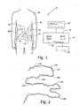
- Fig. 3 showing an estimated error distribution resulting from using a pre-selected value (as opposed to a true value) of the length of a body lumen, and assuming no error due to location detection (the location detection error is not taken into account in this figure), according to one embodiment of the present invention, other values and curves may be used.
- the horizontal axis may mark the number of frames, for an in-vivo device transmitting image frames to an external recorder 12 at, for example, a given frequency.
- the vertical axis may mark the path length traveled through a body lumen determined by location points calculated from transmission signals of each image frame.
- Curve 310 may represent the true distance traveled.
- Curve 320 may represent the estimated distance determined, for example, by the method described herein.
- the greatest discrepancy between the true path length (310) and estimated path length (320) through a body lumen may be near the middle of the body lumen path while the smallest discrepancy between the true (310) and estimated (320) path length through body lumen may be near each of the end points of the body lumen.
- Colonoscopes may only be able to penetrate, for example, a few centimeters beyond the cecum and into the small intestine. As such accuracy near the end points may be of greater importance than accuracy for example half way along the small intestine.
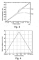
- Fig. 4 showing an exemplary simulated maximum distance error as a function of distance along a small intestine, according to one embodiment of the present invention; other functions may be used, and other lumens may be examined.
- the pylorus may be marked as the entrance of the small intestine and the cecum may be marked as the point of exist of the small intestine.
- the location detection error in this graph may be modeled, for example, as a Rayleigh distribution with, for example, the average distance error of 3.5 cm that may, in some embodiments of the invention, be a typical location detection error.
- other models and error levels may be used.
- this exemplary model as may be seen by the graph in Fig.
- the error of the path length through the body lumen may be in the order of magnitude of 10 cm at a distance of 0.5 meter from an end point (entrance and/or exist) of the small intestine marked by the cecum and pylorus respectively.
- a physician may have indication if a site detected by an autonomous in-vivo device may be revisited by an alternate device and from which direction.
- an in-vivo device may travel through more than one lumen or portion of lumen in its course, for example, esophagus, stomach, and small intestine, it may be useful to be able to locate the end point of the lumen of interest, for example, the small intestine and measure the path length from that end point of that lumen.
- Various methods may be used for this purpose.
- pH measurement may be used to detect a change in pH when entering and/or exiting the stomach.
- a pressure sensor may be used to indicate when device 100 was released from, for example, the small intestine into the roomier large intestine.
- a pressure indicator may be used to detect, for example, the rhythmic peristaltic pressure that may be typical in the small intestine.
- other methods involving post-processing of images may be used to identify mucosa and/or tissue that may, for example, be typically found in a specific body lumen.
- a specific color scheme that may typically be found in a specific body lumen may be used to identify the end points through a body lumen.
- a physician or medical technician may identify through image or other data, the end points of a body lumen and use, for example, user input unit 20 to input that information to path-length detection unit 30.
- an in-vivo device may sense data or a condition from within a body lumen.
- the sensed data may be image data, for example, image data captured within the body lumen of the GI tract.
- Other data may be sensed instead of or in addition to image data, for example, temperature, pressure, motility, etc.
- Data captured or collected may be, for example, transmitted (block 520).
- pure location data e.g., via a carrier signal or other signal
- externally generated signals e.g., X-rays, ultrasound signals
- a signal other than the data sensed may be transmitted to indicate a specified condition was met, for example, a signal to indicate that an in-vivo device may be caught behind a stricture, or other conditions.
- the data transmitted may be picked up by one or more pick up devices, for example one or more antennas 49.
- the transmitted data and the data pertaining to the location of the in-vivo device may be, for example, stored in recorder 12 (block 530).
- the process of sensing (block 510), transmitting (block 520), and storing (block 530) may continue for predetermined time period until all relevant data may be assumed to have been collected and stored. Other methods of determining a suitable time for termination of data collection and storage may be used.
- sensed data and location data may be downloaded to, for example, data processor 14. According to some embodiments no downloading may be required.
- transmitted data may be directed (by wire or wireless connection) to processing unit 14 in real time.
- a user may review data transmitted from an in-vivo device, for example, a stream of images. When reviewing the data, the user may mark one or more images that may be of interest, for example, may show pathology. The image or images of interest may be marked with any suitable user input means 20, for example, keyboard, computer mouse, touch-sensitive screen, and/or other suitable means. Data from the location detection system may be used to determine the location of a site of interest, for example a site where the marked images were captured in-vivo (block 540). In one embodiment of the present invention, a user may mark, for example, images that indicate the entrance and exit points of the body lumen containing the image of interest In other embodiments, marking need not be used, and path length data may be generated independent of specific or requested points.
- Data from the location detection system may be used to determine the location of the end points of the body lumen (block 550).
- the end points of the body lumen may be located without user input, for example, by methods described herein.
- the end points may be recognized by for example, a change of color, visible texture, measured pH, measured pressure, etc.
- the end points may be recognized by using a tissue color bar as may be described in embodiments described in US provisional application 60/507,508 , entitled "Device, System And Method For Presentation Of In-Vivo Data". Other methods of determining end points of body lumens may be implemented.
- the data pertaining to the location of the in-vivo device may be processed to determine the raw path length through the body lumen from the entrance to the exit point (L T ).
- the raw path length from the determined entrance point of the body lumen to the location point of interest (L) may be calculated.
- the actual path length (L A ) may be determined based on raw path lengths L T and L, and a pre-selected length of the overall length of the body lumen. In other embodiments of the present invention, the actual path length (L A ) may be based on other suitable input data besides or in addition to the input data described herein. For example, path lengths L T and L may be preprocessed before calculating their ratio for determining the actual path length.
- the path-length detection unit 30 may perform tasks described in blocks 560 through blocks 580.
- the tasks described in blocks 560 to 580 may be shared by more than one unit or component in system 10, for example the tasks may be shared by location detection system 13.
- a health professional may use the information obtained on the path length to, to help him decide how to proceed with diagnosis or treatment of a patient
- Embodiments of the present invention may include other apparatuses for performing the operations herein. Such apparatuses may integrate the elements discussed, or may comprise alternative components to carry out the same purpose.
Landscapes
- Health & Medical Sciences (AREA)
- Life Sciences & Earth Sciences (AREA)
- Surgery (AREA)
- Engineering & Computer Science (AREA)
- General Health & Medical Sciences (AREA)
- Molecular Biology (AREA)
- Pathology (AREA)
- Veterinary Medicine (AREA)
- Public Health (AREA)
- Biophysics (AREA)
- Biomedical Technology (AREA)
- Heart & Thoracic Surgery (AREA)
- Medical Informatics (AREA)
- Physics & Mathematics (AREA)
- Animal Behavior & Ethology (AREA)
- Optics & Photonics (AREA)
- Nuclear Medicine, Radiotherapy & Molecular Imaging (AREA)
- Radiology & Medical Imaging (AREA)
- Human Computer Interaction (AREA)
- Measurement Of The Respiration, Hearing Ability, Form, And Blood Characteristics Of Living Organisms (AREA)
- Endoscopes (AREA)
- Measuring And Recording Apparatus For Diagnosis (AREA)
Description
- The present invention relates to an in-vivo device traveling through a body lumen, and in particular to a system and method to determine the path length or distance through a body lumen to a specified location.
- The gastrointestinal (GI) tract may typically be a convoluted long tube that folds many times to fit inside the abdomen, proceeding through the esophagus, stomach, small intestine, and large intestine. Autonomous in-vivo devices, for example, ingestible devices that may move through the GI tact, and that may collect data and transmit the data to a receiver system, are known in the art. Such devices may be used to examine areas that may otherwise be difficult to access with non- autonomous devices such as for example, endoscopes, colonscopes, gastroscopes, enteroscopes, laparoscopes, catheters, etc.
- During examination of a patient with an autonomous device, a physician may identify one or more sites of interest. A physician may want to revisit the sites of interest using, for example, an alternate device (e.g. endoscope, colonscope, a second autonomous device etc). Revisiting may be for more examining, sensing, diagnosing, treating, surgery, etc. In some instances, a physician may attempt to revisit a site of interest with a non-autonomous device only to discover that the site of interest is beyond the range that the non-autonomous device can penetrate. In other instances, an attempt to revisit the site of interest may be carried out with more than one alternate device before succeeding in locating the site of interest. This may lead to unnecessary discomfort, cost, and potential risk to the patient.
- It is known from
US 2002/0198470 to provide a device and method for mapping, diagnosing and treating the intestinal tract using a capsule passing through the tract. A capsule tracking system is provided for tracking the capsule's location along a length of the intestinal tract. A map of sensed information may be derived from the pass of the capsule. - Viewed from a first aspect, there is provided a method for determining a path length traveled to a specific location through a body lumen by an in vivo device, the method comprising the steps set forth in
claim 1 of the appended claims. - Various embodiments of the present invention provide a method for determining path length through a body lumen, for example path length or distance to a specified location.
- A raw path length of the in-vivo device traveling to a specified location along a body lumen is compared to a raw path length of the in vivo device traveling through the entire body lumen. The ratio between the two path lengths together with a preselected body lumen length is used to determine a true path length through a body lumen to a specified location. Typically the system may include an in-vivo device, a location detection system and a path-length detection unit. Other configurations may be used.
- The subject matter regarded as the invention is particularly pointed out and distinctly claimed in the concluding portion of the specification. The invention, however, both as to organization and method of operation, together with objects, features and advantages thereof, may best be understood by reference to the following detailed description when read with the accompanied drawings in which:
-
Figure 1 is a schematic illustration of an in-vivo system according to an embodiment of the present invention; -
Figure 2 is a schematic illustration of a simulated body lumen and a superimposed estimated path through measured location points according to an embodiment of the present invention; -
Figure 3 is an estimated maximum error distribution resulting from using an estimated value of the total length of a body lumen, according to an embodiment of the present invention; -
Figure 4 is a simulated maximum distance error as a function of location along a small intestine according to an embodiment of the present invention; and -
Figure 5 is a flow chart describing a method for determining distance through a body lumen according to some embodiment of the present invention. - It will be appreciated that for simplicity and clarity of illustration, elements shown in the figures have not necessarily been drawn to scale. For example, the dimensions of some of the elements may be exaggerated relative to other elements for clarity. Further, where considered appropriate, reference numerals may be repeated among the figures to indicate corresponding or analogous elements.
- In the following description, various aspects of the present invention will be described. For purposes of explanation, specific configurations and details are set forth in order to provide a thorough understanding of the present invention. However, it will also be apparent to one skilled in the art that the present invention may be practiced without the specific details presented herein. Furthermore, well-known features may be omitted or simplified in order not to obscure the present invention.
- Embodiments of the system, and method of the present invention may typically be used in conjunction with an in-vivo sensing device and system such as described in embodiments in
U.S. patent 5,604,531 to Iddan et al . and/or in International Application numberWO 01/65995 WO/03005877 - Embodiments of the in-vivo device that may be used together with the system and method of the present invention may typically be autonomous and may typically be self contained. For example, the in-vivo device may be a capsule or another unit where all the components may be substantially contained within a container or shell, and where the in-vivo device may not require any wires or cables to, for example, receive power or transmit information. The in-vivo device may communicate with an external receiving and display system to provide display of data, control, or other functions. For example, power may be provided by an internal battery or a wireless receiving system. Other embodiments may have other configurations and capabilities. For example, components may be distributed over multiple sites or units. Control information may be received from an external source.
- Embodiments of the present invention may typically include a location detection system for locating the device in vivo, for example, as is described in embodiments of US Patent Application Publication Number
US20020173718, published on November 21, 2001 and entitled "Array System and Method for Locating an In Vivo Signal Source". - It is noted that in other embodiments of the invention, other location detecting methods may be used. For example, in one embodiment of the present of invention, location information may be determined by, for example, including one or more transmitting antennas in an in vivo device, to transmit data using various frequencies, and/or by detecting the location of the in vivo device using components of quasi-static magnetic field(s) - a magnetic method. In some embodiments, methods such as those using ultrasound transceivers or monitors that include, for example, three magnetic coils that receive and transmit positional signals relative to an external constant magnetic field may be used. In yet other embodiments, GPS-like system may be used; for example, a system using transmission from three or more stations. Typically, in some embodiments of the present invention, an array of antennas or sensors may be placed on or close to the abdomen to enable tracking of the in vivo device. Of course, other components or sets of components may be used in accordance with embodiments of the invention.
- In one embodiment, a set of locations of the in-vivo device may be determined, and from these locations a distance or path length may be determined. The locations may be determined from the data that is sensed by the device - for example, a radio signal including image or other data may be analyzed for location.
- Reference is now made to
Fig. 1 showing an in-vivo system 10 according to an embodiment of the present invention. In-vivo system 10 may include an in-vivo device 100, anexternal recorder 12, aprocessing unit 14, adisplay unit 18, and auser input unit 20. In-vivo device 100 may be any suitable traceable or trackable in-vivo device. In some embodiments of the present invention,device 100 may typically be, for example, an in-vivo imaging device, for example as is described in embodiments inU.S. patent 5,604,531 and/or in International Application numberWO 01/65995 antennas 49 that may be, for example, positioned and/or worn on a patient'sbody 50.Recorder 12 may typically be a portable wearable receiving and recording device and may include a signal pick up system, for example,antenna array 49. -
Recorder 12 may, for example, receive signals fromantennas 49 and store them, for example, temporarily in for example, aportable storage unit 19.Recorder 12 may include alocation detection system 13 that may in one embodiment of the invention utilize, for example, a triangulation method to determine the location of in-vivo device 100 relative to theantenna array 49. The triangulation method may be based, for example, on the difference in signal strength picked up from the transmitting in-vivo device by the various antennas inantenna array 49. Typically, thelocation detection system 13 and method may be similar to that described in US Patent Application Publication NumberUS20020173718 . Other suitable location detection systems may be used. In other embodiments of the present invention,location detection system 13 may be wholly or partially integral todata processor 14. - Location data obtained from the
location detection system 13 as well as signals or data transmitted by in-vivo device 100 may be, in one embodiment of the invention, for example, downloaded toprocessor 14 for post-processing, and storage in, for example,storage unit 16. In other embodiments,device 100 may be or include another transmitting device other than an imaging device, for example, an in-vivo device with an RFID tag, ordevice 100 may be, for example, a non-transmitting in-vivo device, for example a marker, or other traceable, trackable or locatable devices. - A physician or other operator may, for example, use an in-
vivo sensing system 10 to, for example, examine, diagnose, check for strictures, treat, and/or perform surgery on a patient. For example, an in-vivo sensing device 100 may, for example, capture images as it travels through the GI tract and transmit them to arecorder 12 external to the body. Anexternal recorder 12 may store the transmitted images as well as other data, for example location data indicating the position in space of the transmitting device. In one embodiment, location data may be determined from sensed data. For example, sensed data such as image data or pressure data may be transmitted, and from the transmissions (e.g., via triangulation) location data may be determined. In other embodiments, the sensed data itself may be analyzed for location data, such as by determining from a set of images distance traveled between images. - After reviewing the transmitted data, for example the images and/or image stream, a physician may identify a site that may be of interest, for example, a location where an in vivo device captured an image(s) indicating, for example, a pathological area in the GI tract that may need further diagnosis, examination, or treatment. In some embodiments of the present invention, a site of interest may be other than a site where pathology may have been identified, a site of interest may be any specified location. In other embodiments, the in-vivo sensing device may include other sensors besides or in addition to image sensors, for example, temperature sensor, pH sensors, blood sensors, etc. and the specified location may be determined based on reviewing data other than image data. In other embodiments of the invention, the in vivo device may be other than a sensing device, or have other functions in addition to sensing, for example, medicine delivery, treatment, or biopsy.
- Following examination and/or treatment with an in-vivo autonomous device, a physician may want to revisit one or more sites or location points of interest using an alternate device (e.g. endoscope, colonscope, gastroscope, enteroscope, laparoscope, and another autonomous in-vivo device, etc). It may be helpful for the physician to know how deep into the body lumen the device may need to be inserted in order to reach the location point of interest This may aid in choosing a procedure, and/or equipment for revisiting. Pre-knowledge of the path length, may help the physician reach the location point of interest more quickly so as to shorten the procedure time (e.g. examination, diagnostic, or treatment) and in that reduce the patient's discomfort. In an alternate embodiment, this information may help a physician decide if it is at all possible to reach the location point of interest with alternate devices. For example, there may be some areas, for example, in the small intestine that may not be reachable with for example with an endoscope, or colonscope, etc. Surgical intervention may be necessary in some circumstances. In some embodiments of the present invention, prior knowledge of the path length to the site may help avoid unsuccessful attempts to approach a site that may not be possible to access. Path length information may be used for other applications. Further, path length other than to a specific or selected location may be obtained using embodiments of the present invention; for example, path length to arbitrary or multiple points, path length after certain times; times to certain path lengths, etc.
- Location detection system, such as
location detection system 13, may be useful for indicating the location of a transmitting device in space, the motility, as well as the speed at given period of time. However, for body lumens that may be convoluted, it may be difficult to deduce how far through a body lumen a device advanced to reach a location point of interest from knowledge of its instantaneous position in space. In addition, it may be difficult to use an instantaneous location in space to locate a site of interest at a later time, since some body lumens may not be stationary over time. An instantaneous location of a site of interest within a body lumen may change over time and thus it may be difficult to predict its location with respect to the shifting body lumen when revisiting the site. - Typically,
processor 14 may also include or be associated with a path-length detection unit 30, to for example, to determine the path length through a body lumen, for example up to a specified location, or in another manner. Data obtained from thelocation detection system 13, as well as other data, may be used as input to path-length detection unit 30. Other data to be used as input to the path-length detection unit 30 may, for example, includeuser input data 20 or data from other features ofsystem 10. Path-length detection unit 30 may in some embodiments include one or more software units withinprocessor 14. - Path-
length detection unit 30 may typically in some embodiments of the present invention, involve post-processing location data obtained fromlocation detection system 13 and, for example, downloaded fromrecorder 12. In some embodiments of the present invention, the path-length detection unit 30 may be a stand-alone unit, may be integral todata processor 14 withstorage unit 16, and/or integral todata recorder 12. The path-length detection unit 30 may typically include processing and storing capability. In some embodiments of the present invention, the path-length detection unit 30 may include input systems for a user, as well as display systems for displaying to the user, for example,display unit 18. Path-length detection unit 30 may, in other embodiments of the present invention, be partially or entirely integral torecorder 12, and may, for example, not receive user input.Processor 14 may typically be a personal computer but may be any suitable unit for processing and/or storing data. Signals, data, and location related data may for example, be displayed ondisplay unit 18. - Reference is now made to
Fig. 2 showing a simulated body lumen path 210 (solid line) that an in-vivo device may be, for example, traveling in and a set of example location points 230, obtained from alocation detection system 13 along the simulated path. An estimated path may be drawn by interpolating between consecutive points to obtain, for example, the estimated path 220 (dashed line). The raw path length may be determined, for example, by integrating the distances between consecutive points using known methods. Small errors may exist when estimating the location data. Errors may be due to, for example, random noise or from thedevice 100 shifting its orientation in-vivo. When estimating the raw path length through, for example,path 220, the small errors in estimating location may accumulate into large errors in estimating a length of a path especially for long paths such as for example, the path of the small intestine, or other paths in the GI tract, or other body lumens. Calculating the path traveled by an in-vivo device using, for example, the estimatedpath 220 may, for example, lead to a path much longer than the true path. Smooching may be used to reduce the error however since the true path may in itself be torturous and unpredictable, it may be difficult to smooth the curve with good precision. - Typically, in some embodiments of the invention, it may be possible to assume that the noise level of the output signal from
location detection system 13 may be substantially similar along the entire path through which the in-vivo device travels. As such, a relative path length (LR) represented by the ratio between raw path length to a location point of interest (L) and the raw total path length though the entire body lumen (LT) may be used to estimate more accurately the path length to a location point of interest without the need of separating, or otherwise eliminating the noise from the signal. In one embodiment, the ratio may be described by the following relationship:
- Other formulas may be used. In one embodiment, a set of calculated paths, such as a calculated total path length in a lumen and a calculated length to a specified point or target or targets, may be determined. The known or estimated total lumen length may be determined, and a ratio between the known or estimated length and the calculated total length may be determined. This ratio may be applied to the calculated path length of the device to the specified point or points, to determine a more accurate estimated path length or distance to the point or points.
- When the in-vivo device may be closer to an existing end point of a body lumen it may be useful for a user to know the relative distance from the existing end point since that may be the direction through which the site may be revisited. As such the following relationship may be used:


- Other formulas may be used. For a clearer indication of the path length from an end point of a body lumen, a pre-selected overall length of the body lumen may be used. For example, the small intestine may be known to be on average 6 to 8 meters long. In one example, 7 meters may be used as a pre-selected value for the length of the small intestine. Using this estimation, the actual path length (LA) may be expressed by the following equations:


- Other formulas may be used.
- Reference is now made to
Fig. 3 showing an estimated error distribution resulting from using a pre-selected value (as opposed to a true value) of the length of a body lumen, and assuming no error due to location detection (the location detection error is not taken into account in this figure), according to one embodiment of the present invention, other values and curves may be used. The horizontal axis may mark the number of frames, for an in-vivo device transmitting image frames to anexternal recorder 12 at, for example, a given frequency. The vertical axis may mark the path length traveled through a body lumen determined by location points calculated from transmission signals of each image frame.Curve 310 may represent the true distance traveled.Curve 320 may represent the estimated distance determined, for example, by the method described herein. - As may be seen by the curves in
Fig. 3 , the greatest discrepancy between the true path length (310) and estimated path length (320) through a body lumen may be near the middle of the body lumen path while the smallest discrepancy between the true (310) and estimated (320) path length through body lumen may be near each of the end points of the body lumen. In some embodiments of the present invention, it may be desirable to estimate the distance through the small intestine so that a site of interest may be revisited for example by an enteroscope and/or a colonscope. Enteroscopes, for example, may only be able to penetrate, for example, approximately a half a meter beyond the top entrance to the small intestine, for example, the pylorus. Colonoscopes, for example, may only be able to penetrate, for example, a few centimeters beyond the cecum and into the small intestine. As such accuracy near the end points may be of greater importance than accuracy for example half way along the small intestine. - Reference is now made to
Fig. 4 showing an exemplary simulated maximum distance error as a function of distance along a small intestine, according to one embodiment of the present invention; other functions may be used, and other lumens may be examined. In this exemplary simulation, the pylorus may be marked as the entrance of the small intestine and the cecum may be marked as the point of exist of the small intestine. The location detection error in this graph may be modeled, for example, as a Rayleigh distribution with, for example, the average distance error of 3.5 cm that may, in some embodiments of the invention, be a typical location detection error. In other embodiments of the present invention, other models and error levels may be used. In this exemplary model, as may be seen by the graph inFig. 4 , the error of the path length through the body lumen may be in the order of magnitude of 10 cm at a distance of 0.5 meter from an end point (entrance and/or exist) of the small intestine marked by the cecum and pylorus respectively. As such, a physician may have indication if a site detected by an autonomous in-vivo device may be revisited by an alternate device and from which direction. - When an in-vivo device may travel through more than one lumen or portion of lumen in its course, for example, esophagus, stomach, and small intestine, it may be useful to be able to locate the end point of the lumen of interest, for example, the small intestine and measure the path length from that end point of that lumen. Various methods may be used for this purpose. For example, pH measurement may be used to detect a change in pH when entering and/or exiting the stomach. A pressure sensor may be used to indicate when
device 100 was released from, for example, the small intestine into the roomier large intestine. In one embodiment of the present invention, a pressure indicator may be used to detect, for example, the rhythmic peristaltic pressure that may be typical in the small intestine. In some embodiments of the present invention, other methods involving post-processing of images may be used to identify mucosa and/or tissue that may, for example, be typically found in a specific body lumen. In other embodiments, for example, a specific color scheme that may typically be found in a specific body lumen may be used to identify the end points through a body lumen. In yet other embodiments, a physician or medical technician may identify through image or other data, the end points of a body lumen and use, for example,user input unit 20 to input that information to path-length detection unit 30. - Reference is now made to
Fig. 5 showing a flow chart describing a method for determining a path length through a body lumen up to a specified location, according to one embodiment of the present invention. Inblock 510 an in-vivo device may sense data or a condition from within a body lumen. In some embodiments of the invention, the sensed data may be image data, for example, image data captured within the body lumen of the GI tract. Other data may be sensed instead of or in addition to image data, for example, temperature, pressure, motility, etc. - Data captured or collected may be, for example, transmitted (block 520). In other embodiments pure location data (e.g., via a carrier signal or other signal) may be transmitted; further, transmission need not occur. For example, externally generated signals (e.g., X-rays, ultrasound signals) may be used to determine location data. In other embodiments of the present invention, a signal other than the data sensed may be transmitted to indicate a specified condition was met, for example, a signal to indicate that an in-vivo device may be caught behind a stricture, or other conditions. The data transmitted may be picked up by one or more pick up devices, for example one or
more antennas 49. The transmitted data and the data pertaining to the location of the in-vivo device (obtained by location detection system 13) may be, for example, stored in recorder 12 (block 530). Typically, the process of sensing (block 510), transmitting (block 520), and storing (block 530) may continue for predetermined time period until all relevant data may be assumed to have been collected and stored. Other methods of determining a suitable time for termination of data collection and storage may be used. - In
block 535, sensed data and location data may be downloaded to, for example,data processor 14. According to some embodiments no downloading may be required. In other embodiments of the present invention, transmitted data may be directed (by wire or wireless connection) toprocessing unit 14 in real time. A user may review data transmitted from an in-vivo device, for example, a stream of images. When reviewing the data, the user may mark one or more images that may be of interest, for example, may show pathology. The image or images of interest may be marked with any suitable user input means 20, for example, keyboard, computer mouse, touch-sensitive screen, and/or other suitable means. Data from the location detection system may be used to determine the location of a site of interest, for example a site where the marked images were captured in-vivo (block 540). In one embodiment of the present invention, a user may mark, for example, images that indicate the entrance and exit points of the body lumen containing the image of interest In other embodiments, marking need not be used, and path length data may be generated independent of specific or requested points. - Data from the location detection system may be used to determine the location of the end points of the body lumen (block 550). In other embodiments of the present invention, the end points of the body lumen may be located without user input, for example, by methods described herein. In other embodiments of the present invention, the end points may be recognized by for example, a change of color, visible texture, measured pH, measured pressure, etc. In other embodiments of the present invention, the end points may be recognized by using a tissue color bar as may be described in embodiments described in
US provisional application 60/507,508 - In
block 560 the data pertaining to the location of the in-vivo device may be processed to determine the raw path length through the body lumen from the entrance to the exit point (LT). Inblock 570 the raw path length from the determined entrance point of the body lumen to the location point of interest (L) may be calculated. Inblock 580 the actual path length (LA) may be determined based on raw path lengths LT and L, and a pre-selected length of the overall length of the body lumen. In other embodiments of the present invention, the actual path length (LA) may be based on other suitable input data besides or in addition to the input data described herein. For example, path lengths LT and L may be preprocessed before calculating their ratio for determining the actual path length. Typically, the path-length detection unit 30 may perform tasks described inblocks 560 throughblocks 580. In other embodiments of the present invention, the tasks described inblocks 560 to 580 may be shared by more than one unit or component insystem 10, for example the tasks may be shared bylocation detection system 13. A health professional may use the information obtained on the path length to, to help him decide how to proceed with diagnosis or treatment of a patient - Other steps and series of steps may be used.
- While the invention has been described with respect to a limited number of embodiments, it will be appreciated that many variations, modifications and other applications of the invention may be made. Embodiments of the present invention may include other apparatuses for performing the operations herein. Such apparatuses may integrate the elements discussed, or may comprise alternative components to carry out the same purpose.
Claims (13)
- A method for determining a path length traveled to a specific location through a body lumen by an in vivo device (100), the method comprising the steps of:pre-selecting an overall length of the body lumen value;determining a raw path length value (L) of the in vivo device (100) through the body lumen to the specific location based upon location data of the in vivo device (100);determining a total raw lumen length value (LT) based upon location data of the in vivo device (100);calculating a relative path length value (LR) as a ratio between the raw path length value (L) and the total raw lumen length value (LT) ;calculating a corrected path length value (LA) using said relative path length value (LR) and said overall length of the body lumen value so as to determine a more accurate estimated path length or distance to the specific location; andproviding the corrected path length value (LA) to a user for use by said user in examination, diagnosis or treatment of said body lumen.
- The method according to claim 1 comprising capturing images of the body lumen as the in vivo device (100) travels through the body lumen.
- The method according to any of claims 1 or 2 comprising sensing pH, pressure or temperature of the body lumen as the in vivo device (100) travels through the body lumen.
- The method according to any of claims 2 or 3 comprising obtaining the location data of the in vivo device (100) based on the captured images or based on data sensed by the in vivo device (100).
- The method according to any of claims 2 or 4 comprising transmitting the captured images to an external receiving system (12, 13, 14).
- The method according to any of claims 1 to 5 wherein the body lumen is the gastrointestinal tract.
- The method according to any of claims 1 to 6 wherein the in vivo device (100) is a swallowable capsule.
- The method according to any of claims 1 to 7 comprising obtaining the location data of the in vivo device (100) based on triangulation of signal strength received by antennas (49) of an external receiving system (13).
- The method according to any of claims 1 to 8 further comprising:post-processing images sent from the in vivo device (100) to identify end points of a portion of a body lumen traveled by the in vivo device (100); andproviding indication to the user if a point of interest may be revisited by an alternate device.
- The method according to claim 9 wherein post-processing images is performed by identifying a color scheme of the images corresponding to a specific body lumen portion.
- The method according to any of claims 9 or 10 further comprising providing a relative distance from a near exit point of a body lumen portion.
- The method according to any of claims 9 to 10 wherein a portion of a body lumen is selected from the group consisting of: esophagus, stomach, and small intestine.
- The method according to any preceding claim wherein the overall length of the body lumen value is between 6 to 8 meters.
Applications Claiming Priority (2)
| Application Number | Priority Date | Filing Date | Title |
|---|---|---|---|
| US10/879,053 US7596403B2 (en) | 2004-06-30 | 2004-06-30 | System and method for determining path lengths through a body lumen |
| PCT/IL2005/000698 WO2006003652A2 (en) | 2004-06-30 | 2005-06-30 | System and method for determining path lengths through a body lumen |
Publications (3)
| Publication Number | Publication Date |
|---|---|
| EP1781168A2 EP1781168A2 (en) | 2007-05-09 |
| EP1781168A4 EP1781168A4 (en) | 2009-04-15 |
| EP1781168B1 true EP1781168B1 (en) | 2013-03-20 |
Family
ID=35514938
Family Applications (1)
| Application Number | Title | Priority Date | Filing Date |
|---|---|---|---|
| EP05755436A Not-in-force EP1781168B1 (en) | 2004-06-30 | 2005-06-30 | Method for determining path lengths through a body lumen |
Country Status (6)
| Country | Link |
|---|---|
| US (2) | US7596403B2 (en) |
| EP (1) | EP1781168B1 (en) |
| JP (1) | JP4966851B2 (en) |
| CN (1) | CN101001568B (en) |
| AU (1) | AU2005258726B2 (en) |
| WO (1) | WO2006003652A2 (en) |
Families Citing this family (41)
| Publication number | Priority date | Publication date | Assignee | Title |
|---|---|---|---|---|
| US9801527B2 (en) | 2004-04-19 | 2017-10-31 | Gearbox, Llc | Lumen-traveling biological interface device |
| US8092549B2 (en) | 2004-09-24 | 2012-01-10 | The Invention Science Fund I, Llc | Ciliated stent-like-system |
| US9011329B2 (en) | 2004-04-19 | 2015-04-21 | Searete Llc | Lumenally-active device |
| US8353896B2 (en) | 2004-04-19 | 2013-01-15 | The Invention Science Fund I, Llc | Controllable release nasal system |
| US8361013B2 (en) | 2004-04-19 | 2013-01-29 | The Invention Science Fund I, Llc | Telescoping perfusion management system |
| US8019413B2 (en) | 2007-03-19 | 2011-09-13 | The Invention Science Fund I, Llc | Lumen-traveling biological interface device and method of use |
| US8337482B2 (en) | 2004-04-19 | 2012-12-25 | The Invention Science Fund I, Llc | System for perfusion management |
| US7577283B2 (en) * | 2005-09-30 | 2009-08-18 | Given Imaging Ltd. | System and method for detecting content in-vivo |
| US7567692B2 (en) * | 2005-09-30 | 2009-07-28 | Given Imaging Ltd. | System and method for detecting content in-vivo |
| US9220917B2 (en) | 2006-04-12 | 2015-12-29 | The Invention Science Fund I, Llc | Systems for autofluorescent imaging and target ablation |
| US9408530B2 (en) | 2006-04-12 | 2016-08-09 | Gearbox, Llc | Parameter-based navigation by a lumen traveling device |
| US8163003B2 (en) * | 2006-06-16 | 2012-04-24 | The Invention Science Fund I, Llc | Active blood vessel sleeve methods and systems |
| US7761134B2 (en) | 2006-10-20 | 2010-07-20 | Given Imaging Ltd. | System and method for modeling a tracking curve of an in vivo device |
| US20090209849A1 (en) * | 2007-05-02 | 2009-08-20 | Philip Stephen Rowe | Medical Device Placement and Monitoring System Utilizing Radio Frequency Identification |
| JP2009022446A (en) * | 2007-07-18 | 2009-02-05 | Given Imaging Ltd | System and method for combined display in medicine |
| JP4914786B2 (en) * | 2007-08-28 | 2012-04-11 | オリンパス株式会社 | In-subject position detection system |
| JP2009226066A (en) * | 2008-03-24 | 2009-10-08 | Olympus Corp | Capsule medical device |
| CN102301233B (en) * | 2009-01-29 | 2015-08-19 | 基文影像公司 | For detecting hemorrhage device, system and method |
| EP2422684A4 (en) | 2009-04-20 | 2014-01-29 | Olympus Medical Systems Corp | Subject internal examination system |
| EP2471439B1 (en) * | 2009-08-28 | 2016-10-19 | Olympus Corporation | Receiver system |
| US9026192B2 (en) * | 2009-11-24 | 2015-05-05 | Given Imaging Ltd | Device and method for in vivo imaging |
| US9615745B2 (en) * | 2009-11-25 | 2017-04-11 | The Brigham And Women's Hospital | System and method for wireless biosensor monitoring |
| WO2011084704A2 (en) * | 2009-12-21 | 2011-07-14 | The Smart Pill Corporation | Tethering capsule system |
| CN103249348B (en) | 2010-07-12 | 2017-07-18 | 瑟拉赛恩传感器股份有限公司 | Apparatus and method for the in vivo monitoring of individual |
| US8403829B2 (en) * | 2010-08-27 | 2013-03-26 | Olympus Medical Systems Corp. | Endoscopic form detection device and form detecting method of insertion section of endoscope |
| EP2606813B1 (en) * | 2011-02-23 | 2014-05-14 | Olympus Medical Systems Corp. | Position information estimation system |
| KR101247165B1 (en) | 2011-04-05 | 2013-03-25 | 전남대학교산학협력단 | Therapeutic Microrobot System for Brain and Spinal Cord Diseases |
| US9097739B2 (en) * | 2011-06-27 | 2015-08-04 | The Johns Hopkins University | System for lightweight image processing |
| US9795330B2 (en) | 2011-12-15 | 2017-10-24 | Given Imaging Ltd. | Device, system and method for in-vivo detection of bleeding in the gastrointestinal tract |
| WO2013088444A2 (en) | 2011-12-15 | 2013-06-20 | Given Imaging Ltd. | Device, system and method for in-vivo detection of bleeding in the gastrointestinal tract |
| US20130261410A1 (en) * | 2012-03-28 | 2013-10-03 | Larger Reality Technologies LLC | System and Method for Body and In-Vivo Device, Motion and Orientation Sensing and Analysis |
| US10045713B2 (en) | 2012-08-16 | 2018-08-14 | Rock West Medical Devices, Llc | System and methods for triggering a radiofrequency transceiver in the human body |
| US9131842B2 (en) | 2012-08-16 | 2015-09-15 | Rock West Solutions, Inc. | System and methods for locating relative positions of multiple patient antennas |
| US9430706B1 (en) | 2013-10-02 | 2016-08-30 | Given Imaging Ltd. | System and method for detection of in-vivo pathology sequences |
| WO2015061343A1 (en) | 2013-10-22 | 2015-04-30 | Rock West Solutions, Inc. | System to localize swallowable pill sensor with three transmitting elements |
| US10143364B2 (en) * | 2015-07-23 | 2018-12-04 | Ankon Technologies Co., Ltd | Controlled image capturing method including position tracking and system used therein |
| TWI562758B (en) * | 2015-11-18 | 2016-12-21 | Univ Nat Chiao Tung | Physiological signal measuring system and method thereof |
| GB201712326D0 (en) * | 2017-08-01 | 2017-09-13 | Univ Southampton | Wearable antenna and intra-uterine monitoring system |
| US20190167226A1 (en) * | 2017-12-04 | 2019-06-06 | International Business Machines Corporation | Infant gastrointestinal monitor |
| US10685486B2 (en) * | 2018-03-29 | 2020-06-16 | Biosense Webster (Israel) Ltd. | Locating an opening of a body cavity |
| CN113064429B (en) * | 2021-03-15 | 2022-04-01 | 江南大学 | Independent driving control system for magnetic micro-robot group |
Family Cites Families (145)
| Publication number | Priority date | Publication date | Assignee | Title |
|---|---|---|---|---|
| US3460528A (en) * | 1965-04-20 | 1969-08-12 | Henry J Carney | Apparatus for locating and removing foreign matter from animal tissue |
| US3683890A (en) | 1970-10-02 | 1972-08-15 | Charles B Beal | Carrier system for delivery of an end of an elongated member to the upper gastrointestinal tract |
| US3971362A (en) | 1972-10-27 | 1976-07-27 | The United States Of America As Represented By The Administrator Of The National Aeronautics And Space Administration | Miniature ingestible telemeter devices to measure deep-body temperature |
| US4262632A (en) | 1974-01-03 | 1981-04-21 | Hanton John P | Electronic livestock identification system |
| US4239040A (en) | 1976-10-19 | 1980-12-16 | Kabushiki Kaisha Daini Seikosha | Capsule for medical use |
| US4178735A (en) | 1977-07-13 | 1979-12-18 | The Kendall Company | Method of sheathing catheter |
| JPS5519124A (en) | 1978-07-27 | 1980-02-09 | Olympus Optical Co | Camera system for medical treatment |
| US5993378A (en) | 1980-10-28 | 1999-11-30 | Lemelson; Jerome H. | Electro-optical instruments and methods for treating disease |
| US4803992A (en) | 1980-10-28 | 1989-02-14 | Lemelson Jerome H | Electro-optical instruments and methods for producing same |
| JPS57156736A (en) | 1981-03-23 | 1982-09-28 | Olympus Optical Co | Therapeutic capsule apparatus |
| JPS57163309A (en) * | 1981-04-01 | 1982-10-07 | Olympus Optical Co Ltd | Capsule apparatus for medical use |
| DE3337455A1 (en) | 1982-10-15 | 1984-04-19 | Olympus Optical Co., Ltd., Tokio/Tokyo | ENDOSCOPIC PHOTOGRAPHER |
| DE3440177A1 (en) | 1984-11-02 | 1986-05-15 | Friedrich Dipl.-Ing. 8031 Eichenau Hilliges | Television recording and replay device for endoscopy on human and animal bodies |
| US4689621A (en) | 1986-03-31 | 1987-08-25 | The United States Of America As Represented By The Administrator Of The National Aeronautics And Space Administration | Temperature responsive transmitter |
| JPS6349125A (en) | 1986-08-16 | 1988-03-01 | 奥津 一郎 | Guide pipe for endoscope |
| US4936823A (en) | 1988-05-04 | 1990-06-26 | Triangle Research And Development Corp. | Transendoscopic implant capsule |
| US4844076A (en) * | 1988-08-26 | 1989-07-04 | The Johns Hopkins University | Ingestible size continuously transmitting temperature monitoring pill |
| DE3836349A1 (en) | 1988-10-25 | 1990-05-03 | Forschungsgesellschaft Fuer Bi | CATHETER FOR MEASURING MOTILITY AND PERISTALTICS IN HOSE-SHAPED ORGANS WHICH CONTAIN THEIR CONTENT BY SIMULTANEOUS MULTIPLE IMPEDANCE MEASUREMENT |
| US4940997A (en) | 1989-08-08 | 1990-07-10 | Hewlett-Packard Company | Out-of-ink sensing method |
| EP0419729A1 (en) * | 1989-09-29 | 1991-04-03 | Siemens Aktiengesellschaft | Position finding of a catheter by means of non-ionising fields |
| US5081041A (en) | 1990-04-03 | 1992-01-14 | Minnesota Mining And Manufacturing Company | Ionic component sensor and method for making and using same |
| JPH0415030A (en) * | 1990-05-09 | 1992-01-20 | Toshiba Corp | Endoscope device |
| GB9018660D0 (en) | 1990-08-24 | 1990-10-10 | Imperial College | Probe system |
| JPH04144533A (en) | 1990-10-05 | 1992-05-19 | Olympus Optical Co Ltd | Endoscope |
| JP3164609B2 (en) | 1990-10-31 | 2001-05-08 | オリンパス光学工業株式会社 | Endoscope device |
| US5267033A (en) | 1990-11-28 | 1993-11-30 | Dai Nippon Printing Co., Ltd. | Hollow body inspection system, hollow body inspection apparatus and signal transmission apparatus |
| CA2060067A1 (en) | 1991-01-28 | 1992-07-29 | Lilip Lau | Stent delivery system |
| US5395366A (en) | 1991-05-30 | 1995-03-07 | The State University Of New York | Sampling capsule and process |
| US5279607A (en) | 1991-05-30 | 1994-01-18 | The State University Of New York | Telemetry capsule and process |
| US5330427A (en) | 1991-07-02 | 1994-07-19 | Ortho Pharmaceutical Corporation | Prefilled suppository applicator |
| EP0531081A1 (en) * | 1991-09-03 | 1993-03-10 | General Electric Company | Tracking system to follow the position and orientation of a device with radiofrequency fields |
| US5211165A (en) | 1991-09-03 | 1993-05-18 | General Electric Company | Tracking system to follow the position and orientation of a device with radiofrequency field gradients |
| FR2688997A1 (en) | 1992-03-26 | 1993-10-01 | Lambert Alain | Autonomous telemetric capsule for exploring small bowel - contains sampler for carrying out mucous biopsies, radio transmitter and position detector |
| AT399229B (en) | 1992-04-23 | 1995-04-25 | Avl Verbrennungskraft Messtech | SENSOR ARRANGEMENT FOR DIRECT OR INDIRECT OPTICAL DETERMINATION OF PHYSICAL OR CHEMICAL PARAMETERS |
| US6996432B2 (en) * | 1992-06-30 | 2006-02-07 | Scimed Life Systems, Inc. | Automated longitudinal position translator for ultrasonic imaging probes, and methods of using same |
| US6757557B1 (en) * | 1992-08-14 | 2004-06-29 | British Telecommunications | Position location system |
| US5913820A (en) | 1992-08-14 | 1999-06-22 | British Telecommunications Public Limited Company | Position location system |
| US5495114A (en) | 1992-09-30 | 1996-02-27 | Adair; Edwin L. | Miniaturized electronic imaging chip |
| JPH06114037A (en) | 1992-10-05 | 1994-04-26 | Olympus Optical Co Ltd | Capsule device for medical treatment |
| JP3020376B2 (en) | 1993-03-26 | 2000-03-15 | サージミヤワキ株式会社 | Internal body identification device for animals |
| JP3321235B2 (en) | 1993-04-07 | 2002-09-03 | オリンパス光学工業株式会社 | Medical capsule and medical capsule detection device |
| US5398670A (en) | 1993-08-31 | 1995-03-21 | Ethicon, Inc. | Lumen traversing device |
| ES2213150T3 (en) | 1993-10-01 | 2004-08-16 | Target Therapeutics, Inc. | MULTIPOLAR CATHETER AND WIRE-GUIDE WITH COVER FOR THE DETECTION OF CARDIAC ELECTRICAL ACTIVITY. |
| JP3279409B2 (en) | 1993-10-18 | 2002-04-30 | オリンパス光学工業株式会社 | Medical capsule device |
| US5479935A (en) | 1993-10-21 | 1996-01-02 | Synectics Medical, Inc. | Ambulatory reflux monitoring system |
| ZA948393B (en) | 1993-11-01 | 1995-06-26 | Polartechnics Ltd | Method and apparatus for tissue type recognition |
| IL108352A (en) | 1994-01-17 | 2000-02-29 | Given Imaging Ltd | In vivo video camera system |
| EP0672427A1 (en) | 1994-03-17 | 1995-09-20 | Siemens-Elema AB | System for infusion of medicine into the body of a patient |
| US5819736A (en) | 1994-03-24 | 1998-10-13 | Sightline Technologies Ltd. | Viewing method and apparatus particularly useful for viewing the interior of the large intestine |
| JP3631265B2 (en) | 1994-04-27 | 2005-03-23 | オリンパス株式会社 | In-vivo observation device |
| US5577502A (en) * | 1995-04-03 | 1996-11-26 | General Electric Company | Imaging of interventional devices during medical procedures |
| US5730129A (en) * | 1995-04-03 | 1998-03-24 | General Electric Company | Imaging of interventional devices in a non-stationary subject |
| DE19532676C1 (en) * | 1995-09-05 | 1997-05-07 | Inst Physikalische Hochtech Ev | Arrangement for determining the position of a marker in a cavity within the organism of a living being |
| US5837196A (en) | 1996-01-26 | 1998-11-17 | The Regents Of The University Of California | High density array fabrication and readout method for a fiber optic biosensor |
| EP0891152B1 (en) * | 1996-02-15 | 2003-11-26 | Biosense, Inc. | Independently positionable transducers for location system |
| DE59706099D1 (en) * | 1996-03-27 | 2002-02-28 | Mednetix Ag Villigen | DEVICE AND METHOD FOR DETERMINING THE POSITION |
| US5782765A (en) * | 1996-04-25 | 1998-07-21 | Medtronic, Inc. | Medical positioning system |
| DE19653535C1 (en) * | 1996-12-20 | 1998-06-10 | Siemens Ag | Position determination method for local antenna in medical MRI system |
| US5946813A (en) * | 1997-02-10 | 1999-09-07 | Leica Geosystems Ag | Method and device for determining correction parameters |
| US6149581A (en) | 1997-06-12 | 2000-11-21 | Klingenstein; Ralph James | Device and method for access to the colon and small bowel of a patient |
| US6324418B1 (en) | 1997-09-29 | 2001-11-27 | Boston Scientific Corporation | Portable tissue spectroscopy apparatus and method |
| US5984875A (en) | 1997-08-22 | 1999-11-16 | Innotek Pet Products, Inc. | Ingestible animal temperature sensor |
| US5929901A (en) | 1997-10-06 | 1999-07-27 | Adair; Edwin L. | Reduced area imaging devices incorporated within surgical instruments |
| US6043839A (en) | 1997-10-06 | 2000-03-28 | Adair; Edwin L. | Reduced area imaging devices |
| US5986693A (en) | 1997-10-06 | 1999-11-16 | Adair; Edwin L. | Reduced area imaging devices incorporated within surgical instruments |
| US6240312B1 (en) * | 1997-10-23 | 2001-05-29 | Robert R. Alfano | Remote-controllable, micro-scale device for use in in vivo medical diagnosis and/or treatment |
| US6369812B1 (en) | 1997-11-26 | 2002-04-09 | Philips Medical Systems, (Cleveland), Inc. | Inter-active viewing system for generating virtual endoscopy studies of medical diagnostic data with a continuous sequence of spherical panoramic views and viewing the studies over networks |
| IL122602A0 (en) | 1997-12-15 | 1998-08-16 | Tally Eitan Zeev Pearl And Co | Energy management of a video capsule |
| US6505062B1 (en) * | 1998-02-09 | 2003-01-07 | Stereotaxis, Inc. | Method for locating magnetic implant by source field |
| US6174291B1 (en) | 1998-03-09 | 2001-01-16 | Spectrascience, Inc. | Optical biopsy system and methods for tissue diagnosis |
| US6395562B1 (en) | 1998-04-22 | 2002-05-28 | The Regents Of The University Of California | Diagnostic microarray apparatus |
| EP1956365B1 (en) * | 1998-08-26 | 2013-01-23 | Sensors for Medicine and Science, Inc. | Optical-based sensing devices |
| US6304766B1 (en) * | 1998-08-26 | 2001-10-16 | Sensors For Medicine And Science | Optical-based sensing devices, especially for in-situ sensing in humans |
| IL126727A (en) | 1998-10-22 | 2006-12-31 | Given Imaging Ltd | Method for delivering a device to a target location |
| US6228048B1 (en) | 1998-10-23 | 2001-05-08 | Cm Robbins Company Inc. | Colonic irrigation apparatus and method |
| US6230038B1 (en) * | 1999-02-01 | 2001-05-08 | International Business Machines Corporation | Imaging of internal structures of living bodies by sensing implanted magnetic devices |
| US7116352B2 (en) | 1999-02-25 | 2006-10-03 | Visionsense Ltd. | Capsule |
| US8636648B2 (en) | 1999-03-01 | 2014-01-28 | West View Research, Llc | Endoscopic smart probe |
| US6285897B1 (en) | 1999-04-07 | 2001-09-04 | Endonetics, Inc. | Remote physiological monitoring system |
| US6233476B1 (en) | 1999-05-18 | 2001-05-15 | Mediguide Ltd. | Medical positioning system |
| JP3490932B2 (en) | 1999-06-07 | 2004-01-26 | ペンタックス株式会社 | Swallowable endoscope device |
| JP3793368B2 (en) | 1999-06-07 | 2006-07-05 | ペンタックス株式会社 | Swallowing endoscope device |
| JP3462795B2 (en) | 1999-06-07 | 2003-11-05 | ペンタックス株式会社 | Swallowable endoscope device |
| IL143258A0 (en) | 2001-05-20 | 2002-04-21 | Given Imaging Ltd | A method for in vivo imaging of the gastrointestinal tract in unmodified conditions |
| US20020015952A1 (en) | 1999-07-30 | 2002-02-07 | Anderson Norman G. | Microarrays and their manufacture by slicing |
| JP2001091860A (en) | 1999-09-22 | 2001-04-06 | Asahi Optical Co Ltd | Capsule endoscope |
| JP2001095756A (en) | 1999-09-30 | 2001-04-10 | Asahi Optical Co Ltd | Capsule type endoscope |
| DE19946948A1 (en) * | 1999-09-30 | 2001-04-05 | Philips Corp Intellectual Pty | Method and arrangement for determining the position of a medical instrument |
| JP2001095755A (en) | 1999-09-30 | 2001-04-10 | Asahi Optical Co Ltd | Capsule type endoscope |
| JP2001104242A (en) | 1999-10-04 | 2001-04-17 | Asahi Optical Co Ltd | Capsule endoscope |
| JP2001104241A (en) | 1999-10-04 | 2001-04-17 | Asahi Optical Co Ltd | Capsule endoscope |
| JP2001104287A (en) | 1999-10-04 | 2001-04-17 | Asahi Optical Co Ltd | Capsule endoscope |
| JP2001104244A (en) | 1999-10-04 | 2001-04-17 | Asahi Optical Co Ltd | Capsule endoscope |
| JP2001104243A (en) | 1999-10-04 | 2001-04-17 | Asahi Optical Co Ltd | Capsule endoscope |
| JP2001112740A (en) | 1999-10-20 | 2001-04-24 | Asahi Optical Co Ltd | Capsulated endoscope |
| JP2001112709A (en) | 1999-10-20 | 2001-04-24 | Asahi Optical Co Ltd | Capsulated endscope |
| JP2001112710A (en) | 1999-10-20 | 2001-04-24 | Asahi Optical Co Ltd | Capsulated endoscope |
| JP4472069B2 (en) | 1999-11-10 | 2010-06-02 | オリンパス株式会社 | Medical capsule endoscope |
| DE19958408A1 (en) * | 1999-12-02 | 2001-06-07 | Philips Corp Intellectual Pty | Magnetic resonance arrangement with devices to localize or visualize instrument inserted in patient; has magnet device controlled and positioned by control unit, to vary position in MRI datasets |
| IL134017A (en) | 2000-01-13 | 2008-04-13 | Capsule View Inc | Camera for viewing inside intestines |
| EP1350103B1 (en) | 2000-01-19 | 2010-01-06 | Given Imaging Ltd. | A system for detecting substances |
| US7039453B2 (en) | 2000-02-08 | 2006-05-02 | Tarun Mullick | Miniature ingestible capsule |
| JP4338280B2 (en) | 2000-02-15 | 2009-10-07 | Hoya株式会社 | Capsule endoscope |
| JP4360730B2 (en) | 2000-02-21 | 2009-11-11 | Hoya株式会社 | Capsule endoscope |
| JP2001245844A (en) | 2000-03-03 | 2001-09-11 | Asahi Optical Co Ltd | Capsule endoscope |
| EP1693000B1 (en) * | 2000-03-08 | 2013-05-08 | Given Imaging Ltd. | A device for in vivo imaging |
| JP3488170B2 (en) | 2000-03-21 | 2004-01-19 | オリンパス株式会社 | Endoscope |
| US6692430B2 (en) | 2000-04-10 | 2004-02-17 | C2Cure Inc. | Intra vascular imaging apparatus |
| US6709387B1 (en) | 2000-05-15 | 2004-03-23 | Given Imaging Ltd. | System and method for controlling in vivo camera capture and display rate |
| US6475145B1 (en) | 2000-05-17 | 2002-11-05 | Baymar, Inc. | Method and apparatus for detection of acid reflux |
| IL163684A0 (en) | 2000-05-31 | 2005-12-18 | Given Imaging Ltd | Measurement of electrical characteristics of tissue |
| US20020099310A1 (en) * | 2001-01-22 | 2002-07-25 | V-Target Ltd. | Gastrointestinal-tract sensor |
| DE10047698A1 (en) * | 2000-09-25 | 2002-04-11 | Zeiss Carl | Medical therapy and / or diagnostic device with a position detection device |
| IL155045A0 (en) * | 2000-09-27 | 2003-10-31 | Given Imaging Ltd | An immobilizable in vivo sensing device |
| DE10051244A1 (en) * | 2000-10-17 | 2002-05-16 | Philips Corp Intellectual Pty | X-ray free intravascular localization and imaging procedure |
| US6632175B1 (en) | 2000-11-08 | 2003-10-14 | Hewlett-Packard Development Company, L.P. | Swallowable data recorder capsule medical device |
| WO2002054932A2 (en) * | 2001-01-16 | 2002-07-18 | Given Imaging Ltd. | System and method for wide field imaging of body lumens |
| US6871086B2 (en) * | 2001-02-15 | 2005-03-22 | Robin Medical Inc. | Endoscopic examining apparatus particularly useful in MRI, a probe useful in such apparatus, and a method of making such probe |
| CN100469308C (en) | 2001-03-14 | 2009-03-18 | 吉温成象有限公司 | Method and system for detecting colorimetric abnormalites |
| AU2002249540A1 (en) | 2001-03-29 | 2002-10-15 | Given Imaging Ltd. | A method for timing control |
| IL143260A (en) | 2001-05-20 | 2006-09-05 | Given Imaging Ltd | Array system and method for locating an in vivo signal source |
| JP4674038B2 (en) | 2001-05-20 | 2011-04-20 | ギブン イメージング リミテッド | In vivo sensing device |
| IL143259A (en) | 2001-05-20 | 2006-08-01 | Given Imaging Ltd | Method for moving an object through the colon |
| US6992477B2 (en) * | 2001-06-15 | 2006-01-31 | Biosense, Inc. | Medical device with position sensor having core with high permeability material for determining location coordinates of a portion of the medical device |
| WO2002102223A2 (en) | 2001-06-20 | 2002-12-27 | Given Imaging Ltd. | Motility analysis within a gastrointestinal tract |
| US7160258B2 (en) * | 2001-06-26 | 2007-01-09 | Entrack, Inc. | Capsule and method for treating or diagnosing the intestinal tract |
| JP4744026B2 (en) | 2001-07-30 | 2011-08-10 | オリンパス株式会社 | Capsule endoscope and capsule endoscope system |
| US6951536B2 (en) | 2001-07-30 | 2005-10-04 | Olympus Corporation | Capsule-type medical device and medical system |
| IL151049A0 (en) | 2001-08-02 | 2003-04-10 | Given Imaging Ltd | In vivo imaging methods and devices |
| IL160736A0 (en) | 2001-09-05 | 2004-08-31 | Given Imaging Ltd | System and method for three dimensional display of body lumens |
| ATE532453T1 (en) | 2001-09-24 | 2011-11-15 | Given Imaging Ltd | SYSTEM FOR CONTROL OF A DEVICE IN VIVO |
| JP3568500B2 (en) * | 2001-09-28 | 2004-09-22 | オリンパス株式会社 | Medical capsule device |
| JP3756797B2 (en) * | 2001-10-16 | 2006-03-15 | オリンパス株式会社 | Capsule type medical equipment |
| US6947787B2 (en) * | 2001-12-21 | 2005-09-20 | Advanced Cardiovascular Systems, Inc. | System and methods for imaging within a body lumen |
| IL154392A (en) | 2002-02-11 | 2010-06-30 | Given Imaging Ltd | Self propelled device having a magnetohydrodynamic propulsion |
| US6958034B2 (en) | 2002-02-11 | 2005-10-25 | Given Imaging Ltd. | Self propelled device |
| US20030195415A1 (en) | 2002-02-14 | 2003-10-16 | Iddan Gavriel J. | Device, system and method for accoustic in-vivo measuring |
| JP3895618B2 (en) | 2002-03-08 | 2007-03-22 | オリンパス株式会社 | Capsule endoscope |
| JP4363843B2 (en) | 2002-03-08 | 2009-11-11 | オリンパス株式会社 | Capsule endoscope |
| JP4009473B2 (en) | 2002-03-08 | 2007-11-14 | オリンパス株式会社 | Capsule endoscope |
| DE10210648A1 (en) * | 2002-03-11 | 2003-10-02 | Siemens Ag | Medical 3-D imaging method for organ and catheter type instrument portrayal in which 2-D ultrasound images, the location and orientation of which are known, are combined in a reference coordinate system to form a 3-D image |
| US20030216622A1 (en) | 2002-04-25 | 2003-11-20 | Gavriel Meron | Device and method for orienting a device in vivo |
| US7473218B2 (en) | 2002-08-06 | 2009-01-06 | Olympus Corporation | Assembling method of capsule medical apparatus |
| US20050065441A1 (en) * | 2003-08-29 | 2005-03-24 | Arkady Glukhovsky | System, apparatus and method for measurement of motion parameters of an in-vivo device |
| JP4144533B2 (en) | 2004-02-24 | 2008-09-03 | ソニー株式会社 | Playback apparatus and method |
-
2004
- 2004-06-30 US US10/879,053 patent/US7596403B2/en active Active
-
2005
- 2005-06-30 AU AU2005258726A patent/AU2005258726B2/en not_active Ceased
- 2005-06-30 JP JP2007518810A patent/JP4966851B2/en not_active Expired - Fee Related
- 2005-06-30 WO PCT/IL2005/000698 patent/WO2006003652A2/en active Application Filing
- 2005-06-30 CN CN2005800268796A patent/CN101001568B/en not_active Expired - Fee Related
- 2005-06-30 EP EP05755436A patent/EP1781168B1/en not_active Not-in-force
-
2009
- 2009-08-06 US US12/536,841 patent/US7865229B2/en active Active
Also Published As
| Publication number | Publication date |
|---|---|
| WO2006003652A2 (en) | 2006-01-12 |
| US7865229B2 (en) | 2011-01-04 |
| CN101001568B (en) | 2011-07-13 |
| AU2005258726A1 (en) | 2006-01-12 |
| CN101001568A (en) | 2007-07-18 |
| US7596403B2 (en) | 2009-09-29 |
| EP1781168A2 (en) | 2007-05-09 |
| JP4966851B2 (en) | 2012-07-04 |
| WO2006003652A3 (en) | 2006-06-22 |
| US20060036166A1 (en) | 2006-02-16 |
| US20090292182A1 (en) | 2009-11-26 |
| EP1781168A4 (en) | 2009-04-15 |
| JP2008504860A (en) | 2008-02-21 |
| AU2005258726B2 (en) | 2011-05-12 |
Similar Documents
| Publication | Publication Date | Title |
|---|---|---|
| EP1781168B1 (en) | Method for determining path lengths through a body lumen | |
| EP1922995B1 (en) | Method for modelling a tracking curve of an in vivo device | |
| US7245954B2 (en) | Measuring a gradient in-vivo | |
| US7200253B2 (en) | Motility analysis within a gastrointestinal tract | |
| EP2123216B1 (en) | Medical Device | |
| EP2290613B1 (en) | System and method for presentation of data streams | |
| US7343036B2 (en) | Imaging method for a capsule-type endoscope unit | |
| JP4520198B2 (en) | In-subject position display system | |
| EP1676522B1 (en) | System for locating an in-vivo signal source | |
| EP2123215B1 (en) | Medical device | |
| US20020107444A1 (en) | Image based size analysis | |
| JP5116070B2 (en) | System for motility measurement and analysis | |
| EP3826527B1 (en) | System and method for polyp detection through capsule dynamics | |
| KR101542354B1 (en) | Endoscope device having distance measuring module, system and method using thereof | |
| CN116919315A (en) | Performance test device and method of cavity detection equipment and electronic equipment | |
| IL159451A (en) | Motility analysis within a gastrointestinaltract |
Legal Events
| Date | Code | Title | Description |
|---|---|---|---|
| PUAI | Public reference made under article 153(3) epc to a published international application that has entered the european phase |
Free format text: ORIGINAL CODE: 0009012 |
|
| 17P | Request for examination filed |
Effective date: 20070116 |
|
| AK | Designated contracting states |
Kind code of ref document: A2 Designated state(s): AT BE BG CH CY CZ DE DK EE ES FI FR GB GR HU IE IS IT LI LT LU MC NL PL PT RO SE SI SK TR |
|
| DAX | Request for extension of the european patent (deleted) | ||
| A4 | Supplementary search report drawn up and despatched |
Effective date: 20090316 |
|
| RIC1 | Information provided on ipc code assigned before grant |
Ipc: A61B 5/06 20060101ALI20090310BHEP Ipc: A61B 5/07 20060101ALI20090310BHEP Ipc: A61B 5/05 20060101AFI20060620BHEP |
|
| RIC1 | Information provided on ipc code assigned before grant |
Ipc: A61B 5/05 20060101AFI20090612BHEP |
|
| 17Q | First examination report despatched |
Effective date: 20091202 |
|
| RAP1 | Party data changed (applicant data changed or rights of an application transferred) |
Owner name: GIVEN IMAGING LTD. |
|
| RIC1 | Information provided on ipc code assigned before grant |
Ipc: A61B 1/04 20060101ALI20120320BHEP Ipc: A61B 5/07 20060101ALI20120320BHEP Ipc: A61B 5/05 20060101AFI20120320BHEP |
|
| GRAP | Despatch of communication of intention to grant a patent |
Free format text: ORIGINAL CODE: EPIDOSNIGR1 |
|
| GRAS | Grant fee paid |
Free format text: ORIGINAL CODE: EPIDOSNIGR3 |
|
| GRAA | (expected) grant |
Free format text: ORIGINAL CODE: 0009210 |
|
| AK | Designated contracting states |
Kind code of ref document: B1 Designated state(s): AT BE BG CH CY CZ DE DK EE ES FI FR GB GR HU IE IS IT LI LT LU MC NL PL PT RO SE SI SK TR |
|
| REG | Reference to a national code |
Ref country code: GB Ref legal event code: FG4D |
|
| REG | Reference to a national code |
Ref country code: CH Ref legal event code: EP |
|
| REG | Reference to a national code |
Ref country code: IE Ref legal event code: FG4D |
|
| REG | Reference to a national code |
Ref country code: AT Ref legal event code: REF Ref document number: 601539 Country of ref document: AT Kind code of ref document: T Effective date: 20130415 |
|
| REG | Reference to a national code |
Ref country code: DE Ref legal event code: R096 Ref document number: 602005038663 Country of ref document: DE Effective date: 20130516 |
|
| PG25 | Lapsed in a contracting state [announced via postgrant information from national office to epo] |
Ref country code: LT Free format text: LAPSE BECAUSE OF FAILURE TO SUBMIT A TRANSLATION OF THE DESCRIPTION OR TO PAY THE FEE WITHIN THE PRESCRIBED TIME-LIMIT Effective date: 20130320 Ref country code: ES Free format text: LAPSE BECAUSE OF FAILURE TO SUBMIT A TRANSLATION OF THE DESCRIPTION OR TO PAY THE FEE WITHIN THE PRESCRIBED TIME-LIMIT Effective date: 20130701 Ref country code: SE Free format text: LAPSE BECAUSE OF FAILURE TO SUBMIT A TRANSLATION OF THE DESCRIPTION OR TO PAY THE FEE WITHIN THE PRESCRIBED TIME-LIMIT Effective date: 20130320 Ref country code: BG Free format text: LAPSE BECAUSE OF FAILURE TO SUBMIT A TRANSLATION OF THE DESCRIPTION OR TO PAY THE FEE WITHIN THE PRESCRIBED TIME-LIMIT Effective date: 20130620 |
|
| REG | Reference to a national code |
Ref country code: AT Ref legal event code: MK05 Ref document number: 601539 Country of ref document: AT Kind code of ref document: T Effective date: 20130320 |
|
| REG | Reference to a national code |
Ref country code: LT Ref legal event code: MG4D |
|
| PG25 | Lapsed in a contracting state [announced via postgrant information from national office to epo] |
Ref country code: GR Free format text: LAPSE BECAUSE OF FAILURE TO SUBMIT A TRANSLATION OF THE DESCRIPTION OR TO PAY THE FEE WITHIN THE PRESCRIBED TIME-LIMIT Effective date: 20130621 Ref country code: SI Free format text: LAPSE BECAUSE OF FAILURE TO SUBMIT A TRANSLATION OF THE DESCRIPTION OR TO PAY THE FEE WITHIN THE PRESCRIBED TIME-LIMIT Effective date: 20130320 Ref country code: FI Free format text: LAPSE BECAUSE OF FAILURE TO SUBMIT A TRANSLATION OF THE DESCRIPTION OR TO PAY THE FEE WITHIN THE PRESCRIBED TIME-LIMIT Effective date: 20130320 |
|
| REG | Reference to a national code |
Ref country code: NL Ref legal event code: VDEP Effective date: 20130320 |
|
| PG25 | Lapsed in a contracting state [announced via postgrant information from national office to epo] |
Ref country code: BE Free format text: LAPSE BECAUSE OF FAILURE TO SUBMIT A TRANSLATION OF THE DESCRIPTION OR TO PAY THE FEE WITHIN THE PRESCRIBED TIME-LIMIT Effective date: 20130320 |
|
| PG25 | Lapsed in a contracting state [announced via postgrant information from national office to epo] |
Ref country code: EE Free format text: LAPSE BECAUSE OF FAILURE TO SUBMIT A TRANSLATION OF THE DESCRIPTION OR TO PAY THE FEE WITHIN THE PRESCRIBED TIME-LIMIT Effective date: 20130320 Ref country code: CZ Free format text: LAPSE BECAUSE OF FAILURE TO SUBMIT A TRANSLATION OF THE DESCRIPTION OR TO PAY THE FEE WITHIN THE PRESCRIBED TIME-LIMIT Effective date: 20130320 Ref country code: SK Free format text: LAPSE BECAUSE OF FAILURE TO SUBMIT A TRANSLATION OF THE DESCRIPTION OR TO PAY THE FEE WITHIN THE PRESCRIBED TIME-LIMIT Effective date: 20130320 Ref country code: NL Free format text: LAPSE BECAUSE OF FAILURE TO SUBMIT A TRANSLATION OF THE DESCRIPTION OR TO PAY THE FEE WITHIN THE PRESCRIBED TIME-LIMIT Effective date: 20130320 Ref country code: AT Free format text: LAPSE BECAUSE OF FAILURE TO SUBMIT A TRANSLATION OF THE DESCRIPTION OR TO PAY THE FEE WITHIN THE PRESCRIBED TIME-LIMIT Effective date: 20130320 Ref country code: PT Free format text: LAPSE BECAUSE OF FAILURE TO SUBMIT A TRANSLATION OF THE DESCRIPTION OR TO PAY THE FEE WITHIN THE PRESCRIBED TIME-LIMIT Effective date: 20130722 Ref country code: RO Free format text: LAPSE BECAUSE OF FAILURE TO SUBMIT A TRANSLATION OF THE DESCRIPTION OR TO PAY THE FEE WITHIN THE PRESCRIBED TIME-LIMIT Effective date: 20130320 Ref country code: IS Free format text: LAPSE BECAUSE OF FAILURE TO SUBMIT A TRANSLATION OF THE DESCRIPTION OR TO PAY THE FEE WITHIN THE PRESCRIBED TIME-LIMIT Effective date: 20130720 |
|
| PG25 | Lapsed in a contracting state [announced via postgrant information from national office to epo] |
Ref country code: PL Free format text: LAPSE BECAUSE OF FAILURE TO SUBMIT A TRANSLATION OF THE DESCRIPTION OR TO PAY THE FEE WITHIN THE PRESCRIBED TIME-LIMIT Effective date: 20130320 Ref country code: CY Free format text: LAPSE BECAUSE OF FAILURE TO SUBMIT A TRANSLATION OF THE DESCRIPTION OR TO PAY THE FEE WITHIN THE PRESCRIBED TIME-LIMIT Effective date: 20130320 |
|
| PLBE | No opposition filed within time limit |
Free format text: ORIGINAL CODE: 0009261 |
|
| STAA | Information on the status of an ep patent application or granted ep patent |
Free format text: STATUS: NO OPPOSITION FILED WITHIN TIME LIMIT |
|
| PG25 | Lapsed in a contracting state [announced via postgrant information from national office to epo] |
Ref country code: DK Free format text: LAPSE BECAUSE OF FAILURE TO SUBMIT A TRANSLATION OF THE DESCRIPTION OR TO PAY THE FEE WITHIN THE PRESCRIBED TIME-LIMIT Effective date: 20130320 Ref country code: MC Free format text: LAPSE BECAUSE OF FAILURE TO SUBMIT A TRANSLATION OF THE DESCRIPTION OR TO PAY THE FEE WITHIN THE PRESCRIBED TIME-LIMIT Effective date: 20130320 |
|
| REG | Reference to a national code |
Ref country code: CH Ref legal event code: PL |
|
| 26N | No opposition filed |
Effective date: 20140102 |
|
| PG25 | Lapsed in a contracting state [announced via postgrant information from national office to epo] |
Ref country code: IT Free format text: LAPSE BECAUSE OF FAILURE TO SUBMIT A TRANSLATION OF THE DESCRIPTION OR TO PAY THE FEE WITHIN THE PRESCRIBED TIME-LIMIT Effective date: 20130320 |
|
| REG | Reference to a national code |
Ref country code: IE Ref legal event code: MM4A |
|
| REG | Reference to a national code |
Ref country code: FR Ref legal event code: ST Effective date: 20140228 |
|
| REG | Reference to a national code |
Ref country code: DE Ref legal event code: R097 Ref document number: 602005038663 Country of ref document: DE Effective date: 20140102 |
|
| PG25 | Lapsed in a contracting state [announced via postgrant information from national office to epo] |
Ref country code: CH Free format text: LAPSE BECAUSE OF NON-PAYMENT OF DUE FEES Effective date: 20130630 Ref country code: LI Free format text: LAPSE BECAUSE OF NON-PAYMENT OF DUE FEES Effective date: 20130630 Ref country code: IE Free format text: LAPSE BECAUSE OF NON-PAYMENT OF DUE FEES Effective date: 20130630 |
|
| PG25 | Lapsed in a contracting state [announced via postgrant information from national office to epo] |
Ref country code: FR Free format text: LAPSE BECAUSE OF NON-PAYMENT OF DUE FEES Effective date: 20130701 |
|
| PG25 | Lapsed in a contracting state [announced via postgrant information from national office to epo] |
Ref country code: TR Free format text: LAPSE BECAUSE OF FAILURE TO SUBMIT A TRANSLATION OF THE DESCRIPTION OR TO PAY THE FEE WITHIN THE PRESCRIBED TIME-LIMIT Effective date: 20130320 |
|
| PG25 | Lapsed in a contracting state [announced via postgrant information from national office to epo] |
Ref country code: HU Free format text: LAPSE BECAUSE OF FAILURE TO SUBMIT A TRANSLATION OF THE DESCRIPTION OR TO PAY THE FEE WITHIN THE PRESCRIBED TIME-LIMIT; INVALID AB INITIO Effective date: 20050630 Ref country code: LU Free format text: LAPSE BECAUSE OF NON-PAYMENT OF DUE FEES Effective date: 20130630 |
|
| PGFP | Annual fee paid to national office [announced via postgrant information from national office to epo] |
Ref country code: DE Payment date: 20210519 Year of fee payment: 17 |
|
| PGFP | Annual fee paid to national office [announced via postgrant information from national office to epo] |
Ref country code: GB Payment date: 20210519 Year of fee payment: 17 |
|
| REG | Reference to a national code |
Ref country code: DE Ref legal event code: R119 Ref document number: 602005038663 Country of ref document: DE |
|
| GBPC | Gb: european patent ceased through non-payment of renewal fee |
Effective date: 20220630 |
|
| PG25 | Lapsed in a contracting state [announced via postgrant information from national office to epo] |
Ref country code: GB Free format text: LAPSE BECAUSE OF NON-PAYMENT OF DUE FEES Effective date: 20220630 Ref country code: DE Free format text: LAPSE BECAUSE OF NON-PAYMENT OF DUE FEES Effective date: 20230103 |