JP4914786B2 - In-subject position detection system - Google Patents
In-subject position detection system Download PDFInfo
- Publication number
- JP4914786B2 JP4914786B2 JP2007221458A JP2007221458A JP4914786B2 JP 4914786 B2 JP4914786 B2 JP 4914786B2 JP 2007221458 A JP2007221458 A JP 2007221458A JP 2007221458 A JP2007221458 A JP 2007221458A JP 4914786 B2 JP4914786 B2 JP 4914786B2
- Authority
- JP
- Japan
- Prior art keywords
- subject
- position detection
- circuit
- electrode
- reception
- Prior art date
- Legal status (The legal status is an assumption and is not a legal conclusion. Google has not performed a legal analysis and makes no representation as to the accuracy of the status listed.)
- Expired - Fee Related
Links
Images


Classifications
-
- A—HUMAN NECESSITIES
- A61—MEDICAL OR VETERINARY SCIENCE; HYGIENE
- A61B—DIAGNOSIS; SURGERY; IDENTIFICATION
- A61B1/00—Instruments for performing medical examinations of the interior of cavities or tubes of the body by visual or photographical inspection, e.g. endoscopes; Illuminating arrangements therefor
- A61B1/04—Instruments for performing medical examinations of the interior of cavities or tubes of the body by visual or photographical inspection, e.g. endoscopes; Illuminating arrangements therefor combined with photographic or television appliances
- A61B1/041—Capsule endoscopes for imaging
-
- A—HUMAN NECESSITIES
- A61—MEDICAL OR VETERINARY SCIENCE; HYGIENE
- A61B—DIAGNOSIS; SURGERY; IDENTIFICATION
- A61B1/00—Instruments for performing medical examinations of the interior of cavities or tubes of the body by visual or photographical inspection, e.g. endoscopes; Illuminating arrangements therefor
-
- A—HUMAN NECESSITIES
- A61—MEDICAL OR VETERINARY SCIENCE; HYGIENE
- A61B—DIAGNOSIS; SURGERY; IDENTIFICATION
- A61B5/00—Measuring for diagnostic purposes; Identification of persons
- A61B5/05—Detecting, measuring or recording for diagnosis by means of electric currents or magnetic fields; Measuring using microwaves or radio waves
- A61B5/053—Measuring electrical impedance or conductance of a portion of the body
-
- A—HUMAN NECESSITIES
- A61—MEDICAL OR VETERINARY SCIENCE; HYGIENE
- A61B—DIAGNOSIS; SURGERY; IDENTIFICATION
- A61B5/00—Measuring for diagnostic purposes; Identification of persons
- A61B5/06—Devices, other than using radiation, for detecting or locating foreign bodies ; determining position of probes within or on the body of the patient
- A61B5/065—Determining position of the probe employing exclusively positioning means located on or in the probe, e.g. using position sensors arranged on the probe
- A61B5/068—Determining position of the probe employing exclusively positioning means located on or in the probe, e.g. using position sensors arranged on the probe using impedance sensors
-
- A—HUMAN NECESSITIES
- A61—MEDICAL OR VETERINARY SCIENCE; HYGIENE
- A61B—DIAGNOSIS; SURGERY; IDENTIFICATION
- A61B5/00—Measuring for diagnostic purposes; Identification of persons
- A61B5/07—Endoradiosondes
Landscapes
- Health & Medical Sciences (AREA)
- Life Sciences & Earth Sciences (AREA)
- Surgery (AREA)
- Engineering & Computer Science (AREA)
- Molecular Biology (AREA)
- General Health & Medical Sciences (AREA)
- Pathology (AREA)
- Biomedical Technology (AREA)
- Heart & Thoracic Surgery (AREA)
- Medical Informatics (AREA)
- Physics & Mathematics (AREA)
- Veterinary Medicine (AREA)
- Animal Behavior & Ethology (AREA)
- Biophysics (AREA)
- Public Health (AREA)
- Nuclear Medicine, Radiotherapy & Molecular Imaging (AREA)
- Radiology & Medical Imaging (AREA)
- Human Computer Interaction (AREA)
- Optics & Photonics (AREA)
- Endoscopes (AREA)
- Measurement Of The Respiration, Hearing Ability, Form, And Blood Characteristics Of Living Organisms (AREA)
- Measurement Of Length, Angles, Or The Like Using Electric Or Magnetic Means (AREA)
- Measurement Of Velocity Or Position Using Acoustic Or Ultrasonic Waves (AREA)
Description
本発明は、被検体の内部に導入された被検体内導入装置の位置情報を導出することが可能な被検体内位置検出システムに関する。 The present invention relates to an in-subject position detection system capable of deriving position information of an in-subject introduction apparatus introduced into a subject.
近年、内視鏡の分野においては、飲み込み型のカプセル型内視鏡(被検体内導入装置)が提案されている。このカプセル型内視鏡は、撮像機能と無線通信機能とを有している。そして、カプセル型内視鏡は、観察(検査)のために被検体の口から飲み込まれた後、自然排出されるまでの間、体腔内、例えば胃や小腸等の臓器の内部をその蠕動運動に従って移動し、画像データ等の被検体内情報を取得する。体腔内を移動する間、カプセル型内視鏡によって体内で得られた画像データは、順次無線通信により外部に送信され、外部に設けられたメモリに蓄積されるようになっている。 In recent years, in the field of endoscopes, swallowable capsule endoscopes (intra-subject introduction devices) have been proposed. This capsule endoscope has an imaging function and a wireless communication function. The capsule endoscope is a peristaltic movement in a body cavity, for example, the inside of an organ such as the stomach or small intestine, after being swallowed from the mouth of the subject for observation (examination) and until it is naturally discharged. To acquire in-subject information such as image data. While moving in the body cavity, image data obtained inside the body by the capsule endoscope is sequentially transmitted to the outside by wireless communication and stored in a memory provided outside.
ここで、カプセル型内視鏡における無線通信方式の一つとして、被検体を信号伝達媒体として利用し画像データを外部に送信する人体通信方式が提案されている。また、人体通信方式のカプセル型内視鏡に関して、被検体内部のカプセル型内視鏡が撮像した画像データの撮像位置を特定するために、カプセル型内視鏡からの画像データを受信する体外受信装置側にカプセル型内視鏡の位置検出を行う機能を持たせたものが提案されている。このような位置検出機能を備えた被検体内位置検出システムの一例として、カプセル型内視鏡から当該カプセル型内視鏡の外周面に配置された電極間の電位差を利用して送信される送信信号を位置検出に利用するものが提案されている(例えば、特許文献1参照)。この特許文献1の例では、カプセル型内視鏡から送信された送信信号が被検体内を介して被検体外部に設けられた体外受信装置の受信用電極において受信され、各々の受信用電極における信号の受信強度の違いに基づいてカプセル型内視鏡の位置が導出される。また、特許文献1の体外受信装置による位置検出方法においては、被検体外に複数配置された受信用電極の中から、順次、受信用電極を選択し、該受信用電極を介して得られる信号の電圧強度をメモリに保存した後、メモリに保存した電圧強度に基づいて、受信に最適な受信用電極の選択を行うことも開示されている。
ここで、画像データの受信後に順次受信用電極を切り替えながらカプセル型内視鏡の位置検出を行う場合、画像データの受信動作と位置検出動作とには時間差が発生する。このような時間差が発生すると、画像データの受信時におけるカプセル型内視鏡の位置と位置検出時におけるカプセル型内視鏡の位置とに誤差が生じるため、カプセル型内視鏡の位置検出精度を欠くことになるおそれがある。 Here, when the position of the capsule endoscope is detected while sequentially switching the receiving electrodes after receiving the image data, a time difference occurs between the image data receiving operation and the position detecting operation. When such a time difference occurs, an error occurs between the position of the capsule endoscope at the time of image data reception and the position of the capsule endoscope at the time of position detection. Therefore, the position detection accuracy of the capsule endoscope is improved. May be missing.
本発明は、上記の事情に鑑みてなされたもので、カプセル型内視鏡の位置検出を高速に行うことで検出精度を向上することが可能な被検体内位置検出システムを提供することを目的とする。 The present invention has been made in view of the above circumstances, and an object thereof is to provide an in-subject position detection system capable of improving detection accuracy by performing position detection of a capsule endoscope at high speed. And
上記の目的を達成するために、本発明の第1の態様の被検体内位置検出システムは、被検体の内部に導入され被検体内情報を取得する被検体内導入装置と、前記被検体の外部に配置され前記被検体の内部における前記被検体内導入装置の位置情報を導出する位置検出装置とを有する被検体内位置検出システムであって、前記被検体内導入装置は、当該被検体内導入装置の外周面に配置され、前記被検体内情報を前記被検体の外部に送信するための送信用電極を具備し、前記位置検出装置は、前記被検体の外表面に配置された複数の受信用電極と、前記複数の受信用電極の中から、前記被検体内情報を受信するための受信用電極を選択する受信用電極選択回路と、前記受信用電極選択回路により選択された受信用電極以外の中から前記被検体内導入装置の位置検出にかかる受信用電極を選択する位置検出用電極選択回路と、前記位置検出用電極選択回路により選択された受信用電極からの電気信号に基づいて前記被検体内導入装置の位置情報を導出する位置情報導出回路とを具備することを特徴とする。 In order to achieve the above object, an in-subject position detection system according to a first aspect of the present invention includes an in-subject introduction apparatus that is introduced into a subject and acquires in-subject information, An in-subject position detection system that includes a position detection device that is arranged outside and that derives position information of the in-subject introduction device inside the subject. It is disposed on the outer peripheral surface of the introduction device, and includes a transmission electrode for transmitting the in-subject information to the outside of the subject. The position detection device includes a plurality of electrodes disposed on the outer surface of the subject. A reception electrode, a reception electrode selection circuit for selecting a reception electrode for receiving the in-vivo information from the plurality of reception electrodes, and a reception electrode selected by the reception electrode selection circuit Inside the subject from other than the electrodes A position detection electrode selection circuit for selecting a reception electrode for position detection of the input device, and a position of the in-subject introduction device based on an electrical signal from the reception electrode selected by the position detection electrode selection circuit And a position information deriving circuit for deriving information.
本発明によれば、カプセル型内視鏡の位置検出を高速に行うことで検出精度を向上することが可能な被検体内位置検出システムを提供することができる。 According to the present invention, it is possible to provide an in-subject position detection system capable of improving detection accuracy by performing position detection of a capsule endoscope at high speed.
以下、図面を参照して本発明の実施形態を説明する。
[第1の実施形態]
まず、本発明の第1の実施形態について説明する。図1は、本発明の第1の実施形態に係る被検体内位置検出システムの全体構成について示す模式図である。図1に示すカプセル型内視鏡システムは、カプセル型内視鏡2と、位置検出装置3と、表示装置4と、携帯型記録媒体5とを備えている。
Hereinafter, embodiments of the present invention will be described with reference to the drawings.
[First Embodiment]
First, a first embodiment of the present invention will be described. FIG. 1 is a schematic diagram showing the overall configuration of the in-subject position detection system according to the first embodiment of the present invention. The capsule endoscope system shown in FIG. 1 includes a
被検体内導入装置としての役割を持つカプセル型内視鏡2は、被検体1の内部に導入され、被検体1の内部を通過経路に沿って移動しながら繰り返し撮像を行って被検体内情報(例えば、被検体1の内部の画像データ)を取得する。
The
位置検出装置3は、カプセル型内視鏡2との間で通信を行うとともに、カプセル型内視鏡2の位置を検出する。図1に示すように位置検出装置3は、受信用電極6a〜6nと、処理装置7とを有している。受信用電極6a〜6nは、被検体1の外表面に配置され、カプセル型内視鏡2からの送信信号を受信するための電極である。処理装置7は、受信用電極6a〜6nにおいて受信された送信信号から被検体1の内部の画像を導出するとともにカプセル型内視鏡2の位置を導出する。
The
表示装置4は、位置検出装置3によって再生された画像データの内容を表示する。この表示装置4は、携帯型記録媒体5によって得られるデータに基づいて画像表示を行うワークステーション等として構成される。より具体的には、表示装置4は、携帯型記録媒体5に記録されたデータから映像信号を再生してCRTディスプレイ、液晶ディスプレイ等に表示する機能を有する。
The display device 4 displays the contents of the image data reproduced by the
携帯型記録媒体5は、処理装置7及び表示装置4に対して着脱可能であって、両者に対する挿着時に情報の出力及び記録が可能な構造を有する。具体的には、携帯型記録媒体5は、カプセル型内視鏡2が被検体1の体腔内を移動している間は処理装置7に挿着されて被検体内の画像及びカプセル型内視鏡2の位置データを記録する。そして、カプセル型内視鏡2が被検体1から排出された後に、処理装置7から取り出されて表示装置4に挿着され、携帯型記録媒体5に記録されているデータが表示装置4によって読み出される。
The
図2は、カプセル型内視鏡2の内部の詳細な構成を示すブロック図である。即ち、カプセル型内視鏡2は、バッテリー8と、電源回路9と、LED10と、LED駆動回路11と、撮像素子(CCD)12と、撮像素子(CCD)駆動回路13と、変調回路14と、整合回路15と、送信用電極16a、16bと、システムコントロール回路17とを有している。
FIG. 2 is a block diagram showing a detailed configuration inside the
バッテリー8は、カプセル型内視鏡2の内部で電力を使用するための電源である。電源回路9は、バッテリー8からカプセル型内視鏡2の内部の各構成要素に供給するための電力を生成し、この電力をカプセル型内視鏡2の各構成要素に供給する。カプセル型内視鏡2の各構成要素は電源回路9から供給される電力を駆動エネルギーとして動作する。
The battery 8 is a power source for using electric power inside the
LED10は、被検体1の内部の撮像を行う際に被検体1の内部の撮像領域を照明するための光源である。LED駆動回路11は、LED10を駆動するための駆動回路である。撮像素子12は、LED10によって照明された撮像領域の少なくとも一部を撮像して被検体内情報(画像信号)を取得するCCD方式の撮像素子である。撮像素子駆動回路13は、撮像素子12を駆動する駆動回路である。撮像素子12において取得された画像信号は、システムコントロール回路17においてデジタル化され、これによって被検体1の体内の画像データが生成される。
The
ここで、光源及び撮像素子として、LED及びCCD方式の撮像素子を用いることは必須ではない。例えば撮像素子としてCMOS方式の撮像素子を用いるようにしても良い。 Here, it is not essential to use an LED and a CCD type image sensor as the light source and the image sensor. For example, a CMOS image sensor may be used as the image sensor.
変調回路14は、システムコントロール回路17において取得された被検体1の画像データに対して変調等の処理を行い、位置検出装置3へデータを送信するための送信信号を生成する。
The
整合回路15は、送信用電極16a、16bと被検体1との間でのインピーダンス整合を行うために、システムコントロール回路17からの指示に従って変調回路14により生成された送信信号の特性インピーダンスを変更する。具体的には、整合回路15は、送信用電極16a、16bとの間に直列または並列に挿入されるインピーダンス可変素子が用いられる。このような整合回路15により、送信信号の特性インピーダンス、送信信号の電力、送信信号の位相、送信信号の周波数などの特性を変更することができる。さらに、整合回路15は、被検体1の内部に流れる電流の最大値を規定するための電流保護抵抗素子を備えている。
The matching
送信用電極16a、16bは、整合回路15から出力される送信信号を被検体1の内部に送信するための電極である。送信用電極16a、16bは導電性を有し、且つ耐食性に優れて人体に無害な金属で構成され、カプセル型内視鏡2の外周面に配置される。
The
システムコントロール回路17は、LED駆動回路11、撮像素子駆動回路13、変調回路14、整合回路15、及び電源回路9の動作を制御するとともに、撮像素子12で得られる画像信号から被検体1の画像データを生成する。
The
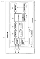
図3は、第1の実施形態における位置検出装置3の内部の詳細な構成を示すブロック図である。上述したように、位置検出装置3は、受信用電極6a〜6nと、処理装置7とを有している。
FIG. 3 is a block diagram showing a detailed configuration inside the
受信用電極6a〜6nは、カプセル型内視鏡2に備わる送信用電極16a、16bから送信された送信信号を受信するための電極である。具体的には、受信用電極6a〜6nは、導電性を有し、さらに耐食性に優れて人体に無害な金属で構成され、被検体1の体表面に配置されている。なお、nは3以上の整数であり、受信用電極の個数を示している。これら受信用電極6a〜6nの中から、処理装置7により選択された受信用電極を用いて、送信信号が受信される。なお、受信用電極6a〜6nの個数、配置される位置、具体的な形状等については図1に示したものに限定されることはなく、任意の構成を採用することができる。例えば、図1では被検体1の正面に受信用電極6a〜6nを配置した例を示しているが、実際にはカプセル型内視鏡2の3次元位置を測定できるように受信用電極6a〜6nを被検体1の側面や背面にも配置することが望ましい。
The
処理装置7は、カプセル型内視鏡2から送信された送信信号を受信して画像データを抽出する機能と、カプセル型内視鏡2から送信された送信信号を受信してカプセル型内視鏡2の位置及び向きを検出する機能とを有する。この処理装置7は、受信用電極選択回路18と、増幅回路19と、受信回路20と、位置検出用電極選択回路21と、増幅回路22と、検出回路23と、信号処理回路24と、位置情報導出部25と、画像記憶部26と、位置情報記憶部27と、バッテリー28と、電源回路29とを有している。
The
受信用電極選択回路18は、受信用電極6a〜6nの中で、信号処理回路24からの受信用電極切り替え信号に従って送信信号の受信に適した1組の受信用電極(以下、受信用電極対と言う)を選択する。増幅回路19は、受信用電極選択回路18により選択された受信用電極対からの受信信号(以下、画像受信信号と言う)に対して差動増幅等の処理を行い、処理後の画像受信信号を検出回路23と信号処理回路24とに出力する。ここで、増幅回路19の内部にカプセル型内視鏡2の送信信号の周波数を中心周波数とするバンドパスフィルタ(BPF)を搭載し、画像受信信号のS/Nを向上させるようにしても良い。なお、このような構成とする場合、送信信号の周波数帯域を通過させるフィルタであれば、ローパスフィルタ(LPF)やハイパスフィルタ(HPF)を用いても良い。受信回路20は、増幅回路19において増幅された画像受信信号に対して復調等の処理を行う。
The reception
位置検出用電極選択回路21は、位置情報導出部25からの位置検出用電極切り替え信号に従って、受信用電極6a〜6nの中から、受信用電極選択回路18で選択された電極以外の受信用電極対を位置検出用の受信用電極として選択する。増幅回路22は、位置検出用電極選択回路21により選択された受信用電極対により受信された位置検出用信号に対して差動増幅等の処理を行う。ここで、増幅回路22の内部にカプセル型内視鏡2の送信信号の周波数を中心周波数とするバンドパスフィルタ(BPF)を搭載し、位置検出用信号のS/Nを向上させるようにしても良い。検出回路23は、増幅回路19または増幅回路22において増幅された信号の信号強度(電圧強度)を検出する。検出回路23の具体的な構成としては、例えば整流回路と平滑回路を用いて受信信号を平滑して信号の振幅を検出する回路が考えられる。この他にも、受信信号の振幅の実行値を抽出する実行値検出回路(true RMSコンバータ)を用いて信号強度を検出しても良く、また受信信号のピークを検出するピーク検出回路を用いて信号強度を検出しても良い。
The position detection
信号処理回路24は、受信回路20の出力信号から被検体内の画像データを抽出する。また、信号処理回路24は、位置情報導出部25において導出されるカプセル型内視鏡2の向き、位置から、最も効率良く送信信号(画像受信信号)の受信が可能な受信用電極対を選択し、その結果を受信用電極切り替え信号として受信用電極選択回路18に出力する。
The
位置情報導出部25は、受信用電極選択回路18によって選択された受信用電極及び位置検出用電極選択回路21によって選択された受信用電極で受信され、検出回路23から信号処理回路24を介して入力される受信信号の信号強度を保存するための図示しないメモリを有し、メモリに保存した受信信号の信号強度から、被検体内に存在するカプセル型内視鏡2の向き、位置を導出する。また、位置情報導出部25は、受信用電極選択回路18によって選択された受信用電極以外の受信用電極を選択するように、位置検出用電極選択回路21に対して位置検出用電極切り替え信号を出力する。
The position
画像記憶部26は、信号処理回路24において抽出された画像データを記憶する。位置情報記憶部27は、位置情報導出部25において導出されたカプセル型内視鏡2の向き、位置のデータを画像記憶部26に記憶される画像データと対応付けて記憶する。これにより、画像データとその撮像位置とを対応付けすることが可能である。画像記憶部26及び位置情報記憶部27に記憶されたデータは、図1に示した携帯型記録媒体5が処理装置7に挿着されたときに携帯型記録媒体5に書き込まれる。
The
バッテリー28は、位置検出装置3の内部で電力を使用するための電源である。電源回路29は、バッテリー28から位置検出装置3の内部の各構成要素に供給するための電力を生成し、この電力を位置検出装置3の各構成要素に供給する。位置検出装置3の各構成要素は電源回路29から供給される電力を駆動エネルギーとして動作する。
The
次に、第1の実施形態に係る被検体内位置検出システムの位置検出動作について説明する。ここで、本実施形態における位置検出動作は、画像データの抽出動作と密接に関わっているため、以下の説明においては、画像データの抽出動作と位置検出動作の併せて説明する。 Next, the position detection operation of the in-subject position detection system according to the first embodiment will be described. Here, since the position detection operation in the present embodiment is closely related to the image data extraction operation, the image data extraction operation and the position detection operation will be described together in the following description.
図4(a)は処理装置7における画像データの抽出動作について示すフローチャートであり、図4(b)は処理装置7における位置検出動作について示すフローチャートである。
FIG. 4A is a flowchart showing an image data extraction operation in the
まず、図4(a)を参照して処理装置7における画像データの抽出動作について説明する。カプセル型内視鏡2の電源回路9が起動されるとカプセル型内視鏡2が正常動作しているかが確認される。カプセル型内視鏡2の正常動作が確認されると、被検体1の体内にカプセル型内視鏡2が導入される。カプセル型内視鏡2が被検体1の体内に導入されると、システムコントロール回路17は、撮像素子駆動回路13を介してCCD12を駆動させて被検体内の撮像を実行する。その後、システムコントロール回路17は、被検体内の撮像によって得られた画像信号に対して、ゲイン補正、色温度補正、データ圧縮等の処理を施して被検体内の画像データを取得する。システムコントロール回路17において得られた画像データは、変調回路14、整合回路15、送信用電極16a、16bを通じて被検体1に出力される。送信用電極16a、16bからの送信信号は、被検体1を伝送媒体として被検体1の体表面に配置された受信用電極6a〜6nに到達する。
First, the image data extraction operation in the
処理装置7の信号処理回路24は、受信用電極6a〜6nの中で、カプセル型内視鏡2からの送信信号(画像受信信号)を受信するのに最適な受信用電極対を選択するように、受信用電極選択回路18に受信用電極切り替え信号を出力する。これを受けて受信用電極選択回路18は、受信用電極の選択を行う(ステップS101)。初回は、受信用電極対を順次選択していき、最適な受信強度となる受信用電極対を送信信号の受信用電極対として使用する。2回目以後は、位置情報導出部25において導出されるカプセル型内視鏡2の向き、位置に基づいて最適な受信用電極を選択する。ここで、このような受信用電極の選択は、カプセル型内視鏡2から送信信号が受信される毎に行うようにしても良いが、カプセル型内視鏡2の向き、位置により現行の受信用電極を変更する必要が生じたときのみ、例えば現行の受信用電極対での受信信号強度が著しく低下したときのみ行うようにしても良い。
The
受信用電極選択回路18によって受信用電極が選択されると、選択された受信用電極を介してカプセル型内視鏡2からの送信信号が受信される。画像受信信号は、増幅回路19において増幅等の処理が行われた後、受信回路20において復調され、信号処理回路24に入力される。信号処理回路24は、受信回路20で復調された信号から画像データを抽出する(ステップS102)。その後、信号処理回路24は、抽出した画像データが被検体内の画像データの先頭であるかを判定する(ステップS103)。これは、例えば、カプセル型内視鏡2からの初回の送信信号の送信時に、画像データとともに該画像データが先頭である旨を示すデータ(例えば垂直同期信号)も送信するようにしておき、信号処理回路24においてこの先頭である旨を示すデータを検出することで判定する。ステップS103の判定において、抽出した画像データが被検体内の画像データの先頭である場合に、信号処理回路24は、位置情報導出部25に対して受信開始信号を出力する(ステップS104)。一方、ステップS103の判定において、抽出した画像データが被検体内の画像データの先頭でない場合に、信号処理回路24は、ステップS104の動作をスキップする。
When a reception electrode is selected by the reception
その後、信号処理回路24は、抽出した画像データを画像記憶部26に記憶させる(ステップS105)。位置情報導出部25に出力された受信強度のデータは位置情報導出部25の図示しないメモリに保存される。その後、信号処理回路24はカプセル型内視鏡2からの送信信号の受信が終了したかを判定する(ステップS106)。ステップS106の判定において、カプセル型内視鏡2からの送信信号の受信が終了していない場合には、処理がステップS101に戻る。一方、ステップS106の判定において、カプセル型内視鏡2からの送信信号の受信が終了した場合、例えば所定時間、カプセル型内視鏡2からの送信信号が受信されない場合には、図4(a)の処理が終了する。
Thereafter, the
以上の図4(a)に示す処理が、被検体内位置検出システムにおけるカプセル型内視鏡2によって取得される被検体内の画像データの抽出に関する処理である。
The process shown in FIG. 4A is a process related to the extraction of the image data in the subject acquired by the
次に、図4(b)を参照して処理装置7における位置検出動作について説明する。位置検出用電極選択回路21は、受信開始信号を受けて位置情報導出部25から出力される位置検出用電極切り替え信号をトリガとして動作を開始する。位置検出用電極選択回路21は、位置検出用電極切り替え信号に従って、受信用電極選択回路18によって選択され画像受信信号の受信に使用されている受信用電極以外の1組の受信用電極を位置検出用の受信用電極対として選択する(ステップS201)。
Next, the position detection operation in the
位置検出用電極選択回路21によって受信用電極が選択されると、選択された受信用電極を介してカプセル型内視鏡2からの送信信号が受信される。受信された信号は、増幅回路22において増幅等の処理が行われる。その後、検出回路23において受信信号の信号強度が検出される。検出回路23において検出された信号強度のデータは信号処理回路24を介して、現在選択されている位置検出用の受信用電極の情報とともに位置情報導出部25の図示しないメモリに保存される。また、受信用電極選択回路18によって選択された受信用電極を介して受信された画像受信信号の強度も検出回路23において検出され、位置情報導出部25のメモリに保存される(ステップS202)。
When a reception electrode is selected by the position detection
その後、位置情報導出部25は、信号強度の検出が終了したか、即ち向き、位置検出に必要な全ての受信用電極の組み合わせで信号強度の検出を行ったかを判定する(ステップS203)。ステップS203の判定において、信号強度の検出が終了していない場合には処理がステップS201に戻る。そして、別の位置検出用の受信用電極を選択する。一方、ステップS203の判定において、信号強度の検出が終了した場合に、位置情報導出部25は、位置検出用電極選択回路21により選択したそれぞれ受信用電極対における受信信号の信号強度と、受信用電極選択回路18により選択した受信用電極からの画像受信信号の信号強度とから、カプセル型内視鏡2の向き、位置を導出する(ステップS204)。次に、位置情報導出部25は、カプセル型内視鏡2の向き、位置データを、画像記憶部26に記憶された画像データと関連付けて位置情報記憶部27に記憶させる(ステップS205)。また、向き、位置データは信号処理回路24にも出力される。この向き、位置から、必要に応じて信号処理回路24は、画像受信信号用の受信用電極の選択を行う。
Thereafter, the position
その後、位置情報導出部25は、カプセル型内視鏡2からの送信信号の受信が終了したかを判定する(ステップS206)。ステップS206の判定において、カプセル型内視鏡2からの送信信号の受信が終了していない場合には、処理がステップS201に戻る。一方、ステップS206の判定において、カプセル型内視鏡2からの送信信号の受信が終了した場合には、図4(b)の処理が終了する。
Thereafter, the position
以上の図4(b)に示す処理が、被検体内位置検出システムにおけるカプセル型内視鏡2の向き、位置の検出に関する処理である。
The process shown in FIG. 4B is a process related to detection of the direction and position of the
図5は、画像抽出動作と位置検出動作の動作タイミングについて示す図である。
図5に示すように、カプセル型内視鏡2による送信信号の送信は、送信信号の送信を行うデータ送信期間と送信信号の送信を行わないデータ非送信期間とが一定の間隔(フレームレート)で繰り返されるように実行される。
FIG. 5 is a diagram illustrating operation timings of the image extraction operation and the position detection operation.
As shown in FIG. 5, in the transmission of the transmission signal by the
信号処理回路24から受信用電極切り替え信号がローレベルからハイレベルに切り替えられると、画像受信信号用の受信用電極が選択される。これにより、カプセル型内視鏡2からの送信信号が、選択された受信用電極に生じる画像受信信号として一定の間隔で繰り返し受信される。データ送信期間が開始されたことが信号処理回路24において認識されると(例えば、画像データの先頭に挿入される垂直または水平同期信号によって認識できる)、位置情報導出部25から位置検出用電極選択回路21に対し、位置検出用電極切り替え信号が送信される。選択された位置検出用の受信用電極を介して受信された信号の信号強度はそのときの受信用電極の組み合わせと関連付けられて位置情報導出部25の図示しないメモリに保存される。さらに、カプセル型内視鏡2のデータ送信期間内において、位置検出用の受信用電極の切り替えがなされながら、信号強度が逐次メモリに保存される。
When the reception electrode switching signal is switched from the low level to the high level from the
向き、位置検出に必要な分の信号強度がメモリに保存されると、位置検出用の受信用電極における受信強度と画像受信用の受信用電極における信号強度とから、カプセル型内視鏡2の向き及び位置と、画像受信用の最適な受信用電極の組み合わせとが導出される。なお、図5の例では、向き、位置の導出と、最適な受信用電極の導出が位置検出用電極の全ての組み合わせにおいて信号強度が検出された後に実行されているが、全ての組み合わせの信号強度がメモリに保存される以前の段階で、向き、位置の導出と、最適な受信用電極の導出とを行っても良い。具体的には、前回導出されたカプセル型内視鏡2の向き、位置をもとに、全ての組み合わせの中の、一部の組み合わせのみで位置検出用の受信用電極における信号強度を検出して、カプセル型内視鏡2の向き、位置、及び最適な受信用電極の組み合わせを導出する。この場合、向き、位置の導出と、最適な受信用電極の導出をデータ送信期間内に行えるようにしても良い。
When the signal intensity required for the direction and position detection is stored in the memory, the
また、最適な受信用電極の導出結果から、画像受信用の受信用電極を変更する場合には、カプセル型内視鏡2のデータ非送信期間にて、信号処理回路24から受信用電極切り替え信号を受信用電極選択回路18に送信するようにする。このようにすることで、カプセル型内視鏡2のデータ送信期間中に受信用電極が変更されることがなく、カプセル型内視鏡2からの送信信号を適切に受信することが可能となる。
When the reception electrode for image reception is changed from the result of derivation of the optimal reception electrode, the reception electrode switching signal is transmitted from the
図6は、位置検出用の受信用電極の選択手順について説明するための平面図である。ここで、図6は、被検体1の体表面に8個(n=8)の受信用電極6a〜6hが配置されており、被検体1の内部に導入されたカプセル型内視鏡2が受信用電極6a〜6hの近傍に存在していることを示す模式図である。
FIG. 6 is a plan view for explaining a procedure for selecting a receiving electrode for position detection. Here, FIG. 6 shows that eight (n = 8) receiving
カプセル型内視鏡2の向き、位置、及び画像受信信号の受信に最適な受信用電極を導出するためには、前述するように、カプセル型内視鏡2におけるデータ送信期間に位置検出用の受信用電極の切り替えを行い、切り替え毎に取得される各々の受信強度から演算することによって求めることができる。
In order to derive the direction and position of the
ここで、カプセル型内視鏡2の向きを高速に検出するための受信用電極対の選択手順として、電極間距離の長い受信用電極対を優先して選択する手法が考えられる。具体的には、図6のように配置された受信用電極に対して、6a−6e、6b−6f、6c−6g、6d−6hのような、電極間距離が長い受信用電極対から選択を開始する。カプセル型内視鏡2が図6の位置に存在している場合、前記の4通りの受信用電極対の条件では6c−6gの組み合わせが最も受信強度が大きくなり、カプセル型内視鏡2の向きも6c―6gの方向に近いことが判明する。なお、前記の4通りの受信用電極対の条件で受信強度の検出を行った後、次に電極間距離が長い組み合わせの受信用電極対に対して受信強度の検出を行うことが好ましい。具体的には、図6のように配置された受信用電極に対して、6b−6h、6f−6h、6d−6f、6b−6dの受信用電極対を選択して受信強度の検出を行う。このようにすることで、向きの検出精度をさらに向上させることが可能である。
Here, as a selection procedure of the reception electrode pair for detecting the direction of the
また、カプセル型内視鏡2の位置を高速に検出するための受信用電極対の選択手順として、前回導出された位置をもとに、1つの受信用電極を基準として、もう一方の受信用電極を順次切り替える手法が考えられる。例としては、前回のカプセル型内視鏡2の位置が図6の位置である場合に、カプセル型内視鏡2に最も近い受信用電極6dを基準電極として他方の受信用電極の選択を開始する。この場合、受信強度の取得数、即ち受信用電極の選択回数に応じて位置の検出精度を向上させることが可能である。
In addition, as a procedure for selecting a receiving electrode pair for detecting the position of the
また、図6では受信用電極が2次元状に配置されている例について説明しているが、受信用電極を3次元状に配置することで、カプセル型内視鏡2の3次元的な向き、位置を検出することも可能である。
FIG. 6 illustrates an example in which the receiving electrodes are arranged in a two-dimensional manner. However, the three-dimensional orientation of the
次に、第1の実施形態に係る被検体内位置検出システムの効果について説明する。前述したように、カプセル型内視鏡2からの送信信号を位置検出装置3で受信する期間内において、処理装置7の受信用電極選択回路18と位置検出用電極選択回路21とを個別に動作させ、画像受信信号の受信用に選択する受信用電極対と位置検出用に選択する受信用電極対を切り替えながら、各受信用電極対の信号強度を検出することができる。その結果、同期間内において画像データの抽出機能と向き、位置の検出機能とを独立に実行することができ、カプセル型内視鏡2における画像取得時の正確な位置を高速に検出することができる。さらに、位置検出用の受信用電極の選択手順を、向き検出と位置検出とで、それぞれ個別に持たせることにより、さらに高速な検出を行うことができる。
Next, the effect of the in-subject position detection system according to the first embodiment will be described. As described above, the reception
また、カプセル型内視鏡2は、その外周面に配置された送信用電極の構成により送信信号が指向性を持つため、被検体1の内部におけるカプセル型内視鏡2の向きの変化により、受信用電極において受信される信号の受信強度が変動する。本実施形態では、画像データの抽出機能と向き、位置の検出機能とを独立して実行できるため、変動した受信用電極における信号強度に対して、すぐに位置検出を実行し、受信用電極の再選択に要する時間を短縮することができる。これによって、受信信号を安定的に受信できるという効果も得ることができる。
In addition, since the transmission signal has directivity due to the configuration of the transmission electrode arranged on the outer peripheral surface of the
[第2の実施形態]
次に、本発明の第2の実施形態について説明する。図7は、本発明の第2の実施形態に係る被検体内位置検出システムにおける位置検出装置3の内部の詳細な構成を示すブロック図である。なお、図7において図3と同様の構成については図3と同様の参照符号を付すことで説明を省略する。また、カプセル型内視鏡2の構成についても第1の実施形態と同様であるので説明を省略する。
[Second Embodiment]
Next, a second embodiment of the present invention will be described. FIG. 7 is a block diagram showing a detailed configuration inside the
図7に示す処理装置7は、図3に示す処理装置7の内部構成に加えてさらに、受信用電極6a〜6nの中から位置検出用電極選択回路21により選択された受信用電極対の間のインピーダンスを検出するインピーダンス測定回路30と、インピーダンス測定回路30により測定されたインピーダンスを記憶するインピーダンス記憶部31とを有している。ここで、インピーダンス測定回路30におけるインピーダンスの測定方法として、具体的には、I−Vコンバータ等を用いた自動平衡ブリッジ法を用いることができる。また、受信用電極間にインピーダンス測定用信号を送信し、その反射信号の成分によりインピーダンス検出を行うブランチラインカプラや方向性結合回路等を用いても良い。
In addition to the internal configuration of the
また、受信用電極間のインピーダンス測定のタイミングは、カプセル型内視鏡2は被検体1の内部へ導入する前にまず行う。そして、カプセル型内視鏡2の正常動作が確認され、被検体1の内部にカプセル型内視鏡2が導入された後は、カプセル型内視鏡2のデータ非送信期間毎にインピーダンスの測定を行う。
The timing of impedance measurement between the receiving electrodes is first performed before the
上述したように、位置情報導出部25は、位置検出用の受信用電極対における信号強度から、カプセル型内視鏡2の向き、位置を導出する。ただし、第2の実施形態においては、受信信号の電圧強度だけではなく、インピーダンス記憶部31に記憶される受信用電極間のインピーダンスを併用することで、電流強度を算出し、該電流強度からカプセル型内視鏡2の向き、位置を導出するようにしても良い。さらに、位置情報導出部25は、インピーダンス記憶部31に記憶される受信用電極間のインピーダンスに応じて信号処理回路24に制御信号を送信する機能を有する。具体的には、受信用電極間のインピーダンスが高インピーダンスである場合には、信号処理回路24にアラーム制御信号を送信する。このアラーム制御信号を受けて、信号処理回路24は、受信用電極と被検体1との未接触状態を検出する。
As described above, the position
図8は、本発明の第2の実施形態の位置検出装置3における受信用電極間のインピーダンスを併用したカプセル型内視鏡2の位置検出について説明するための模式図である。図8に示す位置に、カプセル型内視鏡2が存在する場合、受信用電極対6i−6jにおける信号強度と6l−6kにおける信号強度とを比較すると、これらの信号強度は受信用電極間距離と受信用電極とカプセル型内視鏡2との距離の影響を受ける。
FIG. 8 is a schematic diagram for explaining the position detection of the
ここで、電極間インピーダンスを測定して位置検出に利用することにより、電極間距離による誤差の影響を低減できる。例えば、受信用電極間の距離と受信用電極間のインピーダンスとの関係が異なる場合(例えば、Zij>Zkl:電極間距離は小さいが電極間インピーダンスが大きい場合)は、信号強度による位置検出よりもインピーダンスを利用した電流強度を用いて向き、位置を検出するほうが位置検出の精度が高くなる。 Here, by measuring the impedance between the electrodes and using it for position detection, it is possible to reduce the influence of the error due to the distance between the electrodes. For example, when the relationship between the distance between the electrodes for reception and the impedance between the electrodes for reception is different (for example, Zij> Zkl: the distance between the electrodes is small but the impedance between the electrodes is large), the position detection based on the signal strength The accuracy of position detection is higher when the direction and the position are detected using the current intensity using the impedance.
また、受信用電極対6i−6lと6j−6kとを比較すると、各々の受信用電極間のインピーダンスZijとZjkとが同等であれば、受信用電極対6i−6lと6j−6kとを線対称に分ける位置にカプセル型内視鏡2が存在することになり、そのときの信号強度も同等レベルとなると想定できる。ただし、時間経過に伴う受信用電極間のインピーダンスの変動がある場合、両信号強度にレベル差が生じて信号強度による位置検出に誤差が生じやすくなる。これに対し、第2の実施形態では、定期的に受信用電極間のインピーダンスを測定して位置検出に利用するので、信号強度のみの位置検出よりも高精度に位置検出を行うことが可能である。
Further, when the receiving electrode pairs 6i-6l and 6j-6k are compared, if the impedances Zij and Zjk between the receiving electrodes are equal, the receiving electrode pairs 6i-6l and 6j-6k are connected to each other. It can be assumed that the
ここで、図8では受信用電極が2次元状に配置されている例について説明しているが、受信用電極を3次元状に配置することで、カプセル型内視鏡2の3次元的な向き、位置を検出することも可能である。
Here, FIG. 8 illustrates an example in which the reception electrodes are arranged in a two-dimensional manner. However, the three-dimensional arrangement of the
次に、第2の実施形態に係る被検体内位置検出システムの効果について説明する。前述した構成により、被検体1の体表面に配置された受信用電極間の電圧強度及びインピーダンスから算出可能な電流強度を、位置検出に利用することで、さらに高精度なカプセル型内視鏡2の向き、位置検出が可能となる。
Next, effects of the in-subject position detection system according to the second embodiment will be described. With the above-described configuration, the current intensity that can be calculated from the voltage intensity and the impedance between the receiving electrodes arranged on the body surface of the subject 1 is used for position detection, so that the
また、定期的に受信用電極間のインピーダンスを検出することで、受信用電極と被検体1との接触状態が変化した場合においても、高精度な位置検出を維持することが可能である。 Further, by detecting the impedance between the receiving electrodes periodically, it is possible to maintain highly accurate position detection even when the contact state between the receiving electrode and the subject 1 changes.
以上実施形態に基づいて本発明を説明したが、本発明は上述した実施形態に限定されるものではなく、本発明の要旨の範囲内で種々の変形や応用が可能なことは勿論である。 Although the present invention has been described above based on the embodiments, the present invention is not limited to the above-described embodiments, and various modifications and applications are naturally possible within the scope of the gist of the present invention.
さらに、上記した実施形態には種々の段階の発明が含まれており、開示される複数の構成要件の適当な組合せにより種々の発明が抽出され得る。例えば、実施形態に示される全構成要件からいくつかの構成要件が削除されても、上述したような課題を解決でき、上述したような効果が得られる場合には、この構成要件が削除された構成も発明として抽出され得る。 Further, the above-described embodiments include various stages of the invention, and various inventions can be extracted by appropriately combining a plurality of disclosed constituent elements. For example, even if some configuration requirements are deleted from all the configuration requirements shown in the embodiment, the above-described problem can be solved, and this configuration requirement is deleted when the above-described effects can be obtained. The configuration can also be extracted as an invention.
2…カプセル型内視鏡、3…位置検出装置、4…表示装置、5…携帯型記録媒体、6a〜6n…受信用電極、7…処理装置、8,28…バッテリー、9,29…電源回路、10…LED、11…LED駆動回路、12…撮像素子(CCD)、13…撮像素子(CCD)駆動回路、14…変調回路、15…整合回路、16a,16b…送信用電極、17…システムコントロール回路、18…受信用電極選択回路、19,22…増幅回路、20…受信回路、21…位置検出用電極選択回路、23…検出回路、24…信号処理回路、25…位置情報導出部、26…画像記憶部、27…位置情報記憶部、30…インピーダンス測定回路、31…インピーダンス記憶部
DESCRIPTION OF
Claims (5)
前記被検体内導入装置は、当該被検体内導入装置の外周面に配置され、前記被検体内情報を前記被検体の外部に送信するための送信用電極を具備し、
前記位置検出装置は、
前記被検体の外表面に配置された複数の受信用電極と、
前記複数の受信用電極の中から、前記被検体内情報を受信するための受信用電極を選択する受信用電極選択回路と、
前記受信用電極選択回路により選択された受信用電極以外の中から前記被検体内導入装置の位置検出にかかる受信用電極を選択する位置検出用電極選択回路と、
前記位置検出用電極選択回路により選択された受信用電極からの電気信号に基づいて前記被検体内導入装置の位置情報を導出する位置情報導出回路と、
を具備することを特徴とする被検体内位置検出システム。 An in-subject introduction device that is introduced into the subject and acquires in-subject information, and a position detection device that is arranged outside the subject and derives position information of the in-subject introduction device inside the subject An in-subject position detection system comprising:
The intra-subject introduction device is provided on an outer peripheral surface of the intra-subject introduction device, and includes a transmission electrode for transmitting the intra-subject information to the outside of the subject,
The position detection device includes:
A plurality of receiving electrodes arranged on the outer surface of the subject;
A receiving electrode selection circuit for selecting a receiving electrode for receiving the in-vivo information from the plurality of receiving electrodes;
A position detection electrode selection circuit for selecting a reception electrode for position detection of the in-subject introduction apparatus from other than the reception electrode selected by the reception electrode selection circuit;
A position information deriving circuit for deriving position information of the in-subject introduction device based on an electrical signal from the receiving electrode selected by the position detecting electrode selecting circuit;
An in-subject position detection system comprising:
前記位置情報導出回路は、前記位置検出用電極選択回路により選択された受信用電極からの電気信号と前記インピーダンス測定回路により測定されたインピーダンスとに基づいて前記被検体内導入装置の位置情報を導出することを特徴とする請求項1に記載の被検体内位置検出システム。 The position detection device further includes an impedance measurement circuit for measuring impedance between the plurality of receiving electrodes,
The position information deriving circuit derives position information of the in-subject introduction apparatus based on an electrical signal from the receiving electrode selected by the position detecting electrode selecting circuit and an impedance measured by the impedance measuring circuit. The in-subject position detection system according to claim 1.
Priority Applications (5)
| Application Number | Priority Date | Filing Date | Title |
|---|---|---|---|
| JP2007221458A JP4914786B2 (en) | 2007-08-28 | 2007-08-28 | In-subject position detection system |
| KR1020097027008A KR101101509B1 (en) | 2007-08-28 | 2008-06-03 | Intra-specimen position detecting system and intra-specimen position detecting method |
| PCT/JP2008/060222 WO2009028246A1 (en) | 2007-08-28 | 2008-06-03 | Intra-specimen position detecting system and intra-specimen position detecting method |
| EP08765035.4A EP2181640A4 (en) | 2007-08-28 | 2008-06-03 | Intra-specimen position detecting system and intra-specimen position detecting method |
| US12/698,414 US20100137708A1 (en) | 2007-08-28 | 2010-02-02 | Intra-subject position detection system and intra-subject position detection method |
Applications Claiming Priority (1)
| Application Number | Priority Date | Filing Date | Title |
|---|---|---|---|
| JP2007221458A JP4914786B2 (en) | 2007-08-28 | 2007-08-28 | In-subject position detection system |
Publications (2)
| Publication Number | Publication Date |
|---|---|
| JP2009050541A JP2009050541A (en) | 2009-03-12 |
| JP4914786B2 true JP4914786B2 (en) | 2012-04-11 |
Family
ID=40386975
Family Applications (1)
| Application Number | Title | Priority Date | Filing Date |
|---|---|---|---|
| JP2007221458A Expired - Fee Related JP4914786B2 (en) | 2007-08-28 | 2007-08-28 | In-subject position detection system |
Country Status (5)
| Country | Link |
|---|---|
| US (1) | US20100137708A1 (en) |
| EP (1) | EP2181640A4 (en) |
| JP (1) | JP4914786B2 (en) |
| KR (1) | KR101101509B1 (en) |
| WO (1) | WO2009028246A1 (en) |
Families Citing this family (30)
| Publication number | Priority date | Publication date | Assignee | Title |
|---|---|---|---|---|
| US8956287B2 (en) | 2006-05-02 | 2015-02-17 | Proteus Digital Health, Inc. | Patient customized therapeutic regimens |
| KR101611240B1 (en) | 2006-10-25 | 2016-04-11 | 프로테우스 디지털 헬스, 인코포레이티드 | Controlled activation ingestible identifier |
| ES2930588T3 (en) | 2007-02-01 | 2022-12-19 | Otsuka Pharma Co Ltd | Ingestible Event Marker Systems |
| AU2008216170B2 (en) | 2007-02-14 | 2012-07-26 | Otsuka Pharmaceutical Co., Ltd. | In-body power source having high surface area electrode |
| US8115618B2 (en) | 2007-05-24 | 2012-02-14 | Proteus Biomedical, Inc. | RFID antenna for in-body device |
| DK2313002T3 (en) | 2008-07-08 | 2018-12-03 | Proteus Digital Health Inc | Data basis for edible event fields |
| SG196787A1 (en) | 2009-01-06 | 2014-02-13 | Proteus Digital Health Inc | Ingestion-related biofeedback and personalized medical therapy method and system |
| JP5355169B2 (en) * | 2009-03-24 | 2013-11-27 | オリンパス株式会社 | Capsule type medical device and capsule type medical system |
| JP5284846B2 (en) * | 2009-03-30 | 2013-09-11 | オリンパス株式会社 | In vivo observation system and method of operating the in vivo observation system |
| JP2010240104A (en) * | 2009-04-03 | 2010-10-28 | Olympus Corp | In-vivo observation system and method for driving in-vivo observation system |
| TWI517050B (en) | 2009-11-04 | 2016-01-11 | 普羅托斯數位健康公司 | System for supply chain management |
| TWI557672B (en) | 2010-05-19 | 2016-11-11 | 波提亞斯數位康健公司 | Computer system and computer-implemented method to track medication from manufacturer to a patient, apparatus and method for confirming delivery of medication to a patient, patient interface device |
| EP2491849B1 (en) * | 2010-09-29 | 2013-10-16 | Olympus Medical Systems Corp. | Information processing device and capsule endoscope system |
| KR101580479B1 (en) * | 2011-02-08 | 2015-12-29 | 한국전자통신연구원 | Transmitter, receiver and the method thereof in human body communication |
| CN102302369A (en) * | 2011-05-16 | 2012-01-04 | 深圳市资福技术有限公司 | Wireless positioning device and method for positioning micro in-vivo diagnosis and treatment device |
| WO2015112603A1 (en) | 2014-01-21 | 2015-07-30 | Proteus Digital Health, Inc. | Masticable ingestible product and communication system therefor |
| US9756874B2 (en) | 2011-07-11 | 2017-09-12 | Proteus Digital Health, Inc. | Masticable ingestible product and communication system therefor |
| KR101898964B1 (en) * | 2011-07-21 | 2018-09-14 | 프로테우스 디지털 헬스, 인코포레이티드 | Mobile communication device, system, and method |
| US11744481B2 (en) | 2013-03-15 | 2023-09-05 | Otsuka Pharmaceutical Co., Ltd. | System, apparatus and methods for data collection and assessing outcomes |
| US10084880B2 (en) | 2013-11-04 | 2018-09-25 | Proteus Digital Health, Inc. | Social media networking based on physiologic information |
| US10432322B2 (en) * | 2015-12-11 | 2019-10-01 | Sony Corporation | Transmission/reception device and transmission/reception method |
| KR102215238B1 (en) | 2016-07-22 | 2021-02-22 | 프로테우스 디지털 헬스, 인코포레이티드 | Electromagnetic sensing and detection of ingestible event markers |
| US11006897B2 (en) | 2017-07-18 | 2021-05-18 | Forest Devices, Inc. | Electrode array apparatus, neurological condition detection apparatus, and method of using the same |
| WO2019111470A1 (en) * | 2017-12-07 | 2019-06-13 | オリンパス株式会社 | Communication module, capsule endoscope and reception unit |
| US11478137B2 (en) * | 2019-04-08 | 2022-10-25 | Electronics And Telecommunications Research Institute | Capsule endoscope image receiver and capsule endoscope device having the same |
| US11424775B2 (en) * | 2020-06-03 | 2022-08-23 | Electronics And Telecommunications Research Institute | Human body communication receiver and operating method thereof |
| US11266476B1 (en) | 2021-04-07 | 2022-03-08 | Forest Devices, Inc. | Headgear storage device and method of distribution |
| USD970019S1 (en) | 2021-04-07 | 2022-11-15 | Forest Devices, Inc. | Gel distribution module |
| USD1018861S1 (en) | 2021-04-07 | 2024-03-19 | Forest Devices, Inc. | Headgear |
| US11241182B1 (en) | 2021-04-07 | 2022-02-08 | Forest Devices, Inc. | Gel distribution apparatus and method |
Family Cites Families (11)
| Publication number | Priority date | Publication date | Assignee | Title |
|---|---|---|---|---|
| IL143260A (en) * | 2001-05-20 | 2006-09-05 | Given Imaging Ltd | Array system and method for locating an in vivo signal source |
| KR20040055293A (en) * | 2002-12-20 | 2004-06-26 | 김대은 | The Method and Device of Position Movement Control of Microcapsule-type Endoscope by Diameter Expansion Mechanism |
| JP2004219329A (en) * | 2003-01-16 | 2004-08-05 | Ntt Docomo Inc | Method, system and instrument for measuring position, and in-vivo wireless device |
| KR100873683B1 (en) * | 2003-01-25 | 2008-12-12 | 한국과학기술연구원 | Method and system for data communication in human body and capsule-type endoscope used therein |
| KR100522132B1 (en) * | 2003-01-25 | 2005-10-18 | 한국과학기술연구원 | Data receiving method and apparatus in human body communication system |
| KR20050010590A (en) * | 2003-07-21 | 2005-01-28 | 한국과학기술원 | An endoscope with paramagnetic materials and magnetic force applying device therefor |
| JP4643153B2 (en) * | 2004-02-06 | 2011-03-02 | 株式会社東芝 | Non-invasive biological information imaging device |
| EP1731093B1 (en) * | 2004-03-29 | 2013-01-09 | Olympus Corporation | System for detecting position in examinee |
| US7596403B2 (en) * | 2004-06-30 | 2009-09-29 | Given Imaging Ltd. | System and method for determining path lengths through a body lumen |
| KR100696475B1 (en) * | 2004-11-02 | 2007-03-19 | 삼성에스디아이 주식회사 | Fuel cell for micro-capsule type robot and micro-capsule type robot powered by the same |
| US20090304093A1 (en) * | 2006-08-01 | 2009-12-10 | Intromedic. Co., Ltd | Transmitting device, communication system and method using a medium |
-
2007
- 2007-08-28 JP JP2007221458A patent/JP4914786B2/en not_active Expired - Fee Related
-
2008
- 2008-06-03 WO PCT/JP2008/060222 patent/WO2009028246A1/en active Application Filing
- 2008-06-03 EP EP08765035.4A patent/EP2181640A4/en not_active Withdrawn
- 2008-06-03 KR KR1020097027008A patent/KR101101509B1/en not_active IP Right Cessation
-
2010
- 2010-02-02 US US12/698,414 patent/US20100137708A1/en not_active Abandoned
Also Published As
| Publication number | Publication date |
|---|---|
| EP2181640A4 (en) | 2015-03-25 |
| WO2009028246A1 (en) | 2009-03-05 |
| US20100137708A1 (en) | 2010-06-03 |
| KR20100012090A (en) | 2010-02-05 |
| EP2181640A1 (en) | 2010-05-05 |
| JP2009050541A (en) | 2009-03-12 |
| KR101101509B1 (en) | 2012-01-03 |
Similar Documents
| Publication | Publication Date | Title |
|---|---|---|
| JP4914786B2 (en) | In-subject position detection system | |
| JP5086618B2 (en) | Capsule endoscope | |
| US8177715B2 (en) | Capsule medical system and biological information acquiring method | |
| JP4339798B2 (en) | Data receiving method and receiving apparatus in communication system through human body | |
| JP4286127B2 (en) | In-subject position detection system | |
| WO2005065521A1 (en) | System for sensing movement in subject | |
| JP4422476B2 (en) | In-subject position detection system | |
| WO2005063121A1 (en) | System for sensing position in subject | |
| JP5537744B2 (en) | Antenna connection unit, reception intensity correction device, and capsule endoscope system | |
| WO2005092188A1 (en) | System for detecting position in examinee | |
| JP4805056B2 (en) | In-subject introduction apparatus, extracorporeal reception apparatus, and in-subject information collection system | |
| JP2007061302A (en) | Receiver | |
| US9750394B2 (en) | Endoscope system, endoscope apparatus, and processor | |
| US20090259096A1 (en) | Body-cavity image obeservation apparatus | |
| JP4804831B2 (en) | In-subject information acquisition system | |
| JP4547181B2 (en) | In-subject position detection system | |
| JP4700308B2 (en) | Position detection apparatus and in-subject introduction system | |
| JP2005245596A (en) | Antenna accommodating apparatus and antenna testing system | |
| JP2005278817A (en) | Position detecting system for inside of examinee's body | |
| JP4542398B2 (en) | Receiver | |
| JP2005319095A (en) | Receiver | |
| JP4025766B2 (en) | Receiver and transmitter | |
| KR20150098505A (en) | Capsule endoscopy |
Legal Events
| Date | Code | Title | Description |
|---|---|---|---|
| A621 | Written request for application examination |
Free format text: JAPANESE INTERMEDIATE CODE: A621 Effective date: 20100820 |
|
| TRDD | Decision of grant or rejection written | ||
| A01 | Written decision to grant a patent or to grant a registration (utility model) |
Free format text: JAPANESE INTERMEDIATE CODE: A01 Effective date: 20120110 |
|
| A01 | Written decision to grant a patent or to grant a registration (utility model) |
Free format text: JAPANESE INTERMEDIATE CODE: A01 |
|
| A61 | First payment of annual fees (during grant procedure) |
Free format text: JAPANESE INTERMEDIATE CODE: A61 Effective date: 20120123 |
|
| R150 | Certificate of patent or registration of utility model |
Ref document number: 4914786 Country of ref document: JP Free format text: JAPANESE INTERMEDIATE CODE: R150 Free format text: JAPANESE INTERMEDIATE CODE: R150 |
|
| FPAY | Renewal fee payment (event date is renewal date of database) |
Free format text: PAYMENT UNTIL: 20150127 Year of fee payment: 3 |
|
| S111 | Request for change of ownership or part of ownership |
Free format text: JAPANESE INTERMEDIATE CODE: R313115 |
|
| R350 | Written notification of registration of transfer |
Free format text: JAPANESE INTERMEDIATE CODE: R350 |
|
| S531 | Written request for registration of change of domicile |
Free format text: JAPANESE INTERMEDIATE CODE: R313531 |
|
| R350 | Written notification of registration of transfer |
Free format text: JAPANESE INTERMEDIATE CODE: R350 |
|
| R250 | Receipt of annual fees |
Free format text: JAPANESE INTERMEDIATE CODE: R250 |
|
| LAPS | Cancellation because of no payment of annual fees |