EP1774245B1 - Echangeur thermique integralement metallique et procede de fabrication associe - Google Patents
Echangeur thermique integralement metallique et procede de fabrication associe Download PDFInfo
- Publication number
- EP1774245B1 EP1774245B1 EP06707072A EP06707072A EP1774245B1 EP 1774245 B1 EP1774245 B1 EP 1774245B1 EP 06707072 A EP06707072 A EP 06707072A EP 06707072 A EP06707072 A EP 06707072A EP 1774245 B1 EP1774245 B1 EP 1774245B1
- Authority
- EP
- European Patent Office
- Prior art keywords
- heat exchanger
- projections
- fully
- metal heat
- flat tubes
- Prior art date
- Legal status (The legal status is an assumption and is not a legal conclusion. Google has not performed a legal analysis and makes no representation as to the accuracy of the status listed.)
- Expired - Fee Related
Links
Images


Classifications
-
- F—MECHANICAL ENGINEERING; LIGHTING; HEATING; WEAPONS; BLASTING
- F28—HEAT EXCHANGE IN GENERAL
- F28D—HEAT-EXCHANGE APPARATUS, NOT PROVIDED FOR IN ANOTHER SUBCLASS, IN WHICH THE HEAT-EXCHANGE MEDIA DO NOT COME INTO DIRECT CONTACT
- F28D1/00—Heat-exchange apparatus having stationary conduit assemblies for one heat-exchange medium only, the media being in contact with different sides of the conduit wall, in which the other heat-exchange medium is a large body of fluid, e.g. domestic or motor car radiators
- F28D1/02—Heat-exchange apparatus having stationary conduit assemblies for one heat-exchange medium only, the media being in contact with different sides of the conduit wall, in which the other heat-exchange medium is a large body of fluid, e.g. domestic or motor car radiators with heat-exchange conduits immersed in the body of fluid
- F28D1/04—Heat-exchange apparatus having stationary conduit assemblies for one heat-exchange medium only, the media being in contact with different sides of the conduit wall, in which the other heat-exchange medium is a large body of fluid, e.g. domestic or motor car radiators with heat-exchange conduits immersed in the body of fluid with tubular conduits
- F28D1/053—Heat-exchange apparatus having stationary conduit assemblies for one heat-exchange medium only, the media being in contact with different sides of the conduit wall, in which the other heat-exchange medium is a large body of fluid, e.g. domestic or motor car radiators with heat-exchange conduits immersed in the body of fluid with tubular conduits the conduits being straight
- F28D1/0535—Heat-exchange apparatus having stationary conduit assemblies for one heat-exchange medium only, the media being in contact with different sides of the conduit wall, in which the other heat-exchange medium is a large body of fluid, e.g. domestic or motor car radiators with heat-exchange conduits immersed in the body of fluid with tubular conduits the conduits being straight the conduits having a non-circular cross-section
- F28D1/05366—Assemblies of conduits connected to common headers, e.g. core type radiators
-
- F—MECHANICAL ENGINEERING; LIGHTING; HEATING; WEAPONS; BLASTING
- F28—HEAT EXCHANGE IN GENERAL
- F28F—DETAILS OF HEAT-EXCHANGE AND HEAT-TRANSFER APPARATUS, OF GENERAL APPLICATION
- F28F9/00—Casings; Header boxes; Auxiliary supports for elements; Auxiliary members within casings
- F28F9/02—Header boxes; End plates
-
- B—PERFORMING OPERATIONS; TRANSPORTING
- B21—MECHANICAL METAL-WORKING WITHOUT ESSENTIALLY REMOVING MATERIAL; PUNCHING METAL
- B21D—WORKING OR PROCESSING OF SHEET METAL OR METAL TUBES, RODS OR PROFILES WITHOUT ESSENTIALLY REMOVING MATERIAL; PUNCHING METAL
- B21D53/00—Making other particular articles
- B21D53/02—Making other particular articles heat exchangers or parts thereof, e.g. radiators, condensers fins, headers
- B21D53/08—Making other particular articles heat exchangers or parts thereof, e.g. radiators, condensers fins, headers of both metal tubes and sheet metal
-
- F—MECHANICAL ENGINEERING; LIGHTING; HEATING; WEAPONS; BLASTING
- F28—HEAT EXCHANGE IN GENERAL
- F28F—DETAILS OF HEAT-EXCHANGE AND HEAT-TRANSFER APPARATUS, OF GENERAL APPLICATION
- F28F9/00—Casings; Header boxes; Auxiliary supports for elements; Auxiliary members within casings
- F28F9/001—Casings in the form of plate-like arrangements; Frames enclosing a heat exchange core
- F28F9/002—Casings in the form of plate-like arrangements; Frames enclosing a heat exchange core with fastening means for other structures
-
- F—MECHANICAL ENGINEERING; LIGHTING; HEATING; WEAPONS; BLASTING
- F28—HEAT EXCHANGE IN GENERAL
- F28F—DETAILS OF HEAT-EXCHANGE AND HEAT-TRANSFER APPARATUS, OF GENERAL APPLICATION
- F28F9/00—Casings; Header boxes; Auxiliary supports for elements; Auxiliary members within casings
- F28F9/02—Header boxes; End plates
- F28F9/0219—Arrangements for sealing end plates into casing or header box; Header box sub-elements
- F28F9/0224—Header boxes formed by sealing end plates into covers
-
- F—MECHANICAL ENGINEERING; LIGHTING; HEATING; WEAPONS; BLASTING
- F28—HEAT EXCHANGE IN GENERAL
- F28F—DETAILS OF HEAT-EXCHANGE AND HEAT-TRANSFER APPARATUS, OF GENERAL APPLICATION
- F28F9/00—Casings; Header boxes; Auxiliary supports for elements; Auxiliary members within casings
- F28F9/02—Header boxes; End plates
- F28F9/04—Arrangements for sealing elements into header boxes or end plates
- F28F9/16—Arrangements for sealing elements into header boxes or end plates by permanent joints, e.g. by rolling
- F28F9/18—Arrangements for sealing elements into header boxes or end plates by permanent joints, e.g. by rolling by welding
- F28F9/182—Arrangements for sealing elements into header boxes or end plates by permanent joints, e.g. by rolling by welding the heat-exchange conduits having ends with a particular shape, e.g. deformed; the heat-exchange conduits or end plates having supplementary joining means, e.g. abutments
-
- F—MECHANICAL ENGINEERING; LIGHTING; HEATING; WEAPONS; BLASTING
- F28—HEAT EXCHANGE IN GENERAL
- F28F—DETAILS OF HEAT-EXCHANGE AND HEAT-TRANSFER APPARATUS, OF GENERAL APPLICATION
- F28F9/00—Casings; Header boxes; Auxiliary supports for elements; Auxiliary members within casings
- F28F9/02—Header boxes; End plates
- F28F9/04—Arrangements for sealing elements into header boxes or end plates
- F28F9/16—Arrangements for sealing elements into header boxes or end plates by permanent joints, e.g. by rolling
- F28F9/18—Arrangements for sealing elements into header boxes or end plates by permanent joints, e.g. by rolling by welding
- F28F9/185—Arrangements for sealing elements into header boxes or end plates by permanent joints, e.g. by rolling by welding with additional preformed parts
-
- F—MECHANICAL ENGINEERING; LIGHTING; HEATING; WEAPONS; BLASTING
- F28—HEAT EXCHANGE IN GENERAL
- F28F—DETAILS OF HEAT-EXCHANGE AND HEAT-TRANSFER APPARATUS, OF GENERAL APPLICATION
- F28F2225/00—Reinforcing means
- F28F2225/08—Reinforcing means for header boxes
-
- F—MECHANICAL ENGINEERING; LIGHTING; HEATING; WEAPONS; BLASTING
- F28—HEAT EXCHANGE IN GENERAL
- F28F—DETAILS OF HEAT-EXCHANGE AND HEAT-TRANSFER APPARATUS, OF GENERAL APPLICATION
- F28F2275/00—Fastening; Joining
- F28F2275/04—Fastening; Joining by brazing
-
- Y—GENERAL TAGGING OF NEW TECHNOLOGICAL DEVELOPMENTS; GENERAL TAGGING OF CROSS-SECTIONAL TECHNOLOGIES SPANNING OVER SEVERAL SECTIONS OF THE IPC; TECHNICAL SUBJECTS COVERED BY FORMER USPC CROSS-REFERENCE ART COLLECTIONS [XRACs] AND DIGESTS
- Y10—TECHNICAL SUBJECTS COVERED BY FORMER USPC
- Y10T—TECHNICAL SUBJECTS COVERED BY FORMER US CLASSIFICATION
- Y10T29/00—Metal working
- Y10T29/49—Method of mechanical manufacture
- Y10T29/4935—Heat exchanger or boiler making
Definitions
- the heat exchanger described above is for example from the DE 198 19 247 A1 known.
- the projections correspond there with openings in the tube sheets.
- a provisional cohesion of the items is provided before performing the soldering process.
- the cost of soldering auxiliary device can be significantly reduced.
- a certain disadvantage of the known heat exchanger is that there is still a clear overhang of the tube bottom over the rib-flat tube block, which could be regarded as an unnecessary space requirement.
- the ratio of the cross sections occupied by the flat tubes is not optimal in comparison with the entire cross section of the heat exchanger or its tube plates, so that improvements are possible with regard to efficient heat exchange.
- the flat tubes extend over the entire depth of the tubesheet, preferably even beyond, there is virtually no space that would not be available for heat exchange purposes.
- the flow-through cross-sectional area of the flat tubes is in a more favorable ratio to the total occupied by the tube sheet surface, which in turn is about equal to the relevant area, which is occupied by the entire heat exchanger.
- the first alternative mentioned as mentioned, preferred because it is better to prevent the already mentioned "collapse" of the flat tubes, since in this case the edge of the headers with the projections from the outside rests on the edge of the tube sheet and therefore because the projections against Forces which act in the direction of the broad side, ie transversely to the longitudinal direction of the flat tubes, are particularly resistant. Furthermore, this alternative also appears to be more favorable in terms of creating dense connections.
- the projections each touch the narrow sides of the flat tubes from the inside and they are preferably soldered there.
- each collection box has frontal openings.
- each collection box turns out to be merely a sheet with two folds, which is also advantageous in terms of manufacturing technology.
- the all-metal heat exchanger can be used everywhere in the widest sense with advantages where a small space requirement with good heat exchange efficiency should be present.
- the inventor remembers to use such heat exchangers especially as air-cooled intercoolers in motor vehicles, but without excluding any other possible use, especially in the field of motor vehicles.
- the seated in the flat tube ends projections on a comb-like additional part, such as metal strips or the like., which is connected to the wall of the header, keep the flat tubes during the subsequent soldering process to tension, so that the risk of the aforementioned "incidence "the flat tubes, with the result of insufficient solder joints in the receiving openings, has been significantly reduced by the provision of the additional part.
- the advantages of the prior art are retained, i. H.
- the cost of soldering auxiliary devices is significantly reduced, since the strips (additional parts) at the ends have hooks that support the cohesion of the mounted items of the heat exchanger by grabbing over the side panels.
- the additional part is a comb-like sheet metal strip, which is easy to process by forming technology to produce the additional part.
- the term "strip" encompasses all possible physical formations, so that it is therefore generally possible to speak of an additional part.
- the mentioned projections on the strips or additional parts may be first projections, in the event that the strip second projections are provided.
- the second protrusions are then arranged between the first protrusions. The second protrusions improve the assembly or preparation of the heat exchanger for the following soldering process.
- the inventive method for producing a whole-metal heat exchanger wherein flat tubes and ribs are merged into a flat-tube fin block, after which tube plates are attached to the ends of the flat tubes and finally collecting boxes are attached with their edges to the edges of the tube sheets is characterized in that arranged on a component projections in the narrow sides of the flat tubes are inserted in the ends thereof.
- All illustrated individual parts of the heat exchanger are made of metal, preferably of aluminum or aluminum alloys, which is expediently coated with a layer of solder.
- the items such as flat tubes 1, ribs 4, tubesheets 5, 6 manifolds and side panels 30 are made of sheets, which, however, is not excluded that, for example, the flat tubes 1 could also be produced as drawn tubes.
- the flat tubes 1 have an approximately rectangular cross-section, but the narrow sides 2 can also be curved slightly outwards. In the embodiment shown, internal inserts are located in the flat tubes 1. The flat tubes 1 are then stacked with the ribs 4 to form a flat tube fins block.
- the webs 22 are present.
- the webs 22 may be formed profiled to increase their rigidity.
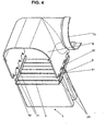
- the side parts 30 are attached, which simultaneously close the frontal openings 60 of the collecting tanks 6 .
- the side panels 30 each have a cup-shaped reshaped at their ends A closure piece that fits into the opening 60 .
- deformable holding elements 61 which engage in a slot 62 of the side parts, the side parts 30 are pre-fixed and hold the individual parts of the heat exchanger together.
- the heat exchanger is substantially prepared to carry out the CAB brazing process. All connections are made in a single pass in a brazing furnace.
- the shape of the projections 11 is suitably adapted to the existing in the narrow sides 2 contour of the flat tubes 1 , so that both the insertion is facilitated as well as dense solder joints are provided. This also certain manufacturing tolerances are absorbed.
- the distance between the projections 11 at the edge of the manifolds 6 corresponds to the distance between the flat tubes 1 in the row or with the height of the arranged between the flat tubes 1 ribs 4.
- certain tolerances must be allowed, however, by the appropriate shape of the projections 11th can be compensated. (see the description of the Fig. 15 and 16 further down)
- the tubesheets 5 during assembly can also be pushed transversely to their longitudinal direction, or in the direction of the broad sides 3 of the flat tube ends, onto the same. In the prior art, this requires a movement in the longitudinal direction of the flat tubes. There is talk of "pulling up" the tubesheets.
- the projections 11 have a favorable effect on the reduction of the harmful bypass, which comes as a further advantage of the invention to bear.
- the small gaps in the corners of the flat tube 1 have their cause in the representation. In practice, they are not available or are securely closed during the soldering process. The mentioned gaps will also level when inserting the projections 11 , because the projections 11 hold both broad sides 3 in the direction of the arrow under a certain tension.
- the collecting boxes 6 also include the tubesheets 5 , so that therefore no classical tubesheets are provided as a single part, which can be taken from the mentioned figures.
- the collecting box 6 has a base section 106 , from which two bent walls 107 of the collecting tank 6 depart. The walls 107 are deformed and they can be connected by means of a longitudinal weld, not shown, to form the header 6 .
- receiving openings 21 are provided for the flat tube ends, which should therefore match the distances of the flat tubes 1 with the distances of the receiving openings 21 .
- strip 110 comes from the Fig. 12 out.
- the strip 110 with the mentioned additional functions is formed, can also make a contribution to the strength of the collecting tank 6 .
- FIGS. 13 and 14 It is further apparent that it is advantageous to form at the ends of the strip 110 a hook 13 which is adapted to hold the side member 30 to the outer rib 4 firmly. This also supports the cohesion of the entire heat exchanger before soldering. Furthermore, it also suppresses the above-mentioned "sticking out" of the strip 110 from the wall 107 . It can also be used in the Fig. 1 With 61 and 62 shown brackets, which should hold the side panels 30 in the frontal openings 60 of the collecting tank 6 , are omitted, which is also a manufacturing advantage.
- the Fig. 15 shows a section with only one projection 11.
- the projections 11 have been performed on the type of cutting teeth 111 .
- length tolerances in the flat tubes which are approximately in the range of +/- 1.0mm are better absorbed.
- sharp edges 112 were formed, which are also in the radii, d. h in the region of the transition from the projection 11 in the wall of the collecting tank 6 or the additional part or the tube bottom extend.
- the sharp edged edges 112 intersect these ends when inserting the projections 11 into the flat tube ends, somewhat at the flat tubes which are in the upper length tolerance range, and "fold" these ends slightly outwards. That is from the Fig. 16 easy to recognize at k.
- the middle tube is slightly longer there than the other two tubes.
- the sharp edge of the projections 11 is produced for example by cold forming.
- the difference in thickness between the projections 11 and the wall of the flat tubes supports this procedure.
- the wall of the collecting box 6, from which the projections 11 are formed for example, may be about 1.0 - 2.0mm thick while the thickness of the
- the invention accordingly provides an innovative product which, compared to the state of the art, leaves only little to be desired.
Landscapes
- Engineering & Computer Science (AREA)
- Mechanical Engineering (AREA)
- Physics & Mathematics (AREA)
- Thermal Sciences (AREA)
- General Engineering & Computer Science (AREA)
- Details Of Heat-Exchange And Heat-Transfer (AREA)
- Heat-Exchange Devices With Radiators And Conduit Assemblies (AREA)
Claims (23)
- Echangeur de chaleur entièrement en métal, constitué de tubes plats (1) avec deux côtés étroits et deux côtés larges (2, 3) et d'ailettes (4) qui forment un bloc conjointement avec les tubes plats, et qui soit présente au moins une plaque à tubes (5) et une caisse collectrice (6), des bords (10) de la caisse collectrice (6) étant connectés à des bords (20) de la plaque à tubes (5), par exemple par brasage, soit possède au moins une caisse collectrice (6) qui contient la plaque à tubes,
et avec des saillies (11) disposées à intervalles,
caractérisé en ce que
les intervalles entre les saillies (11) correspondent aux intervalles entre les tubes plats (1) de sorte que les saillies (11) viennent en prise dans la région des côtés étroits (2) avec les extrémités des tubes plats (1). - Echangeur de chaleur entièrement en métal selon la revendication 1, caractérisé en ce que les tubes plats (1) dépassent avec leurs côtés étroits (2) au-delà de la largeur de la plaque à tubes (5) et les saillies (11) viennent en prise avec les extrémités des tubes plats (1) dans la région qui dépasse.
- Echangeur de chaleur entièrement en métal selon la revendication 1, caractérisé en ce que la largeur de la plaque à tubes dépasse au-delà des côtés étroits (2) des tubes plats (1) et les saillies (11) viennent en prise avec les extrémités des tubes plats (1) dans la région qui dépasse.
- Echangeur de chaleur entièrement en métal selon l'une quelconque des revendications précédentes, caractérisé en ce que les saillies (11) sont à chaque fois en contact par l'intérieur avec les côtés étroits (2) des tubes plats (1) et sont de préférence soudées à ceux-ci à cet endroit.
- Echangeur de chaleur entièrement en métal selon l'une quelconque des revendications précédentes, caractérisé en ce que les saillies (11) sont de préférence disposées sur les bords longitudinaux (10) de la caisse collectrice (6).
- Echangeur de chaleur entièrement en métal selon l'une quelconque des revendications précédentes, caractérisé en ce que la plaque à tubes (5) présente, de manière connue en soi, au niveau des côtés longitudinaux opposés, des bords recourbés (20) et des ouvertures (21) pour recevoir à chaque fois une extrémité de tube plat (1), les ouvertures (21) s'étendant vers l'intérieur jusque dans les bords longitudinaux recourbés (20).
- Echangeur de chaleur entièrement en métal selon l'une quelconque des revendications précédentes, caractérisé en ce que les plaques à tubes (5) présentent des bords recourbés (20) uniquement au niveau des deux côtés longitudinaux, de sorte qu'elles puissent être fabriquées à partir d'une bande de tôle de longueur quelconque.
- Echangeur de chaleur entièrement en métal selon l'une quelconque des revendications précédentes, caractérisé en ce que la caisse collectrice (6) présente des ouvertures (60) du côté frontal.
- Echangeur de chaleur entièrement en métal selon l'une quelconque des revendications précédentes, caractérisé en ce que l'échangeur de chaleur présente des parties latérales (30) connues en soi qui s'étendent sur la longueur des tubes plats (1) et qui ferment les ouvertures (60) du côté frontal des caisses collectrices (6).
- Echangeur de chaleur entièrement en métal selon la revendication 1, caractérisé en ce que les saillies (11) sont disposées sur la plaque à tubes (5) ou en ce que l'on utilise un cadre présentant les saillies (11).
- Echangeur de chaleur entièrement en métal selon l'une quelconque des revendications précédentes, caractérisé en ce que les saillies (11) sont réalisées sur une pièce supplémentaire (110) qui s'étend le long de la paroi (107) de la caisse collectrice (6) et qui lui est connectée.
- Echangeur de chaleur entièrement en métal selon les revendications 1 et 11, caractérisé en ce que la caisse collectrice (6) présente deux parois (107) recourbées sur une portion de base (106), et est réalisée avec des ouvertures de réception (21) pour les extrémités des tubes.
- Echangeur de chaleur entièrement en métal selon la revendication 12, caractérisé en ce que les ouvertures de réception (21) s'étendent jusque dans les parois (107) de la caisse collectrice (6).
- Echangeur de chaleur entièrement en métal selon les revendications 11 ou 12, caractérisé en ce que la pièce supplémentaire (110) s'applique depuis l'extérieur approximativement à plat contre la paroi (107) de la caisse collectrice (6).
- Echangeur de chaleur entièrement en métal selon l'une quelconque des revendications précédentes 11 à 14, caractérisé en ce que la pièce supplémentaire (110) présente d'autres fonctions, par exemple des fonctions de retenue (90) pour des accessoires ou autres.
- Echangeur de chaleur entièrement en métal selon l'une quelconque des revendications précédentes 11 à 15, caractérisé en ce que la pièce supplémentaire (110) peut avoir un contour qui correspond au contour de la paroi (107) de la caisse collectrice.
- Echangeur de chaleur entièrement en métal selon l'une quelconque des revendications précédentes 11 à 16, caractérisé en ce que les saillies (11) sont des premières saillies (11), la pièce supplémentaire (110) présentant des deuxièmes saillies (12) entre les premières saillies (11).
- Echangeur de chaleur entièrement en métal selon l'une quelconque des revendications précédentes 11 à 17, caractérisé en ce que la pièce supplémentaire (110) est réalisée à l'extrémité avec un crochet (13) ou similaire, approprié pour fixer une partie latérale (30) de l'échangeur de chaleur.
- Echangeur de chaleur entièrement en métal selon l'une quelconque des revendications précédentes, caractérisé en ce que les saillies (11) sont formées de telle sorte, par exemple sous forme conique, que leur insertion dans les extrémités des tubes plats (1) soit facilitée.
- Echangeur de chaleur entièrement en métal selon l'une quelconque des revendications précédentes, caractérisé en ce que les saillies (11) sont réalisées à la manière de dents de coupe (111).
- Echangeur de chaleur entièrement en métal selon l'une quelconque des revendications précédentes, caractérisé en ce que l'échangeur de chaleur peut de préférence être utilisé comme refroidisseur d'air de charge à refroidissement à air.
- Procédé de fabrication d'un échangeur de chaleur entièrement en métal, comprenant les étapes suivantes :les tubes plats et les ailettes sont assemblés pour former un bloc de tubes plats et d'ailettes ; les plaques à tubes sont placées contre les extrémités des tubes plats ;les caisses collectrices sont placées avec leurs bords contre les bords des plaques à tubes,caractérisé en ce que des saillies (11) disposées sur un composant sont enfoncées dans la région des côtés étroits (2) des tubes plats (1) dans leurs extrémités.
- Procédé de fabrication selon la revendication 22, caractérisé en ce que les bords longitudinaux (10) de la caisse collectrice (6), présentant les saillies (11), sont appliqués de préférence depuis l'extérieur contre les bords (20) de la plaque à tubes (5), les saillies (11) étant enfoncées dans les extrémités des tubes plats (1).
Priority Applications (1)
| Application Number | Priority Date | Filing Date | Title |
|---|---|---|---|
| EP06707072A EP1774245B1 (fr) | 2005-06-11 | 2006-02-18 | Echangeur thermique integralement metallique et procede de fabrication associe |
Applications Claiming Priority (4)
| Application Number | Priority Date | Filing Date | Title |
|---|---|---|---|
| EP05012589A EP1731864A1 (fr) | 2005-06-11 | 2005-06-11 | Echangeur de chaleur métallique et procédé de fabrication de celui-ci |
| EP05020325A EP1764570A1 (fr) | 2005-09-17 | 2005-09-17 | Echangeur de chaleur entierement métallique |
| EP06707072A EP1774245B1 (fr) | 2005-06-11 | 2006-02-18 | Echangeur thermique integralement metallique et procede de fabrication associe |
| PCT/EP2006/001487 WO2006133748A1 (fr) | 2005-06-11 | 2006-02-18 | Echangeur thermique integralement metallique et procede de fabrication associe |
Publications (2)
| Publication Number | Publication Date |
|---|---|
| EP1774245A1 EP1774245A1 (fr) | 2007-04-18 |
| EP1774245B1 true EP1774245B1 (fr) | 2008-02-20 |
Family
ID=36123144
Family Applications (1)
| Application Number | Title | Priority Date | Filing Date |
|---|---|---|---|
| EP06707072A Expired - Fee Related EP1774245B1 (fr) | 2005-06-11 | 2006-02-18 | Echangeur thermique integralement metallique et procede de fabrication associe |
Country Status (7)
| Country | Link |
|---|---|
| US (1) | US20080230213A1 (fr) |
| EP (1) | EP1774245B1 (fr) |
| KR (1) | KR100957665B1 (fr) |
| BR (1) | BRPI0611998A2 (fr) |
| DE (1) | DE502006000358D1 (fr) |
| ES (1) | ES2302323T3 (fr) |
| WO (1) | WO2006133748A1 (fr) |
Cited By (2)
| Publication number | Priority date | Publication date | Assignee | Title |
|---|---|---|---|---|
| DE102008051422A1 (de) | 2008-10-11 | 2010-04-15 | Modine Manufacturing Co., Racine | Ganz-Metall-Wärmetauscher und Verfahren |
| DE102009059692A1 (de) | 2009-12-19 | 2011-06-22 | Modine Manufacturing Co., Wis. | Wärmetauscherblock und Herstellungsverfahren |
Families Citing this family (15)
| Publication number | Priority date | Publication date | Assignee | Title |
|---|---|---|---|---|
| DE102006058096A1 (de) * | 2006-12-09 | 2008-06-12 | Modine Manufacturing Co., Racine | Ganz-Metall-Wärmetauscher |
| US20100032149A1 (en) * | 2006-07-08 | 2010-02-11 | Helmut Roll | Heat exchanger and method of manufacturing the same |
| DE102007027706A1 (de) | 2007-06-15 | 2008-12-18 | Modine Manufacturing Co., Racine | Wärmetauscher |
| FR2933175B1 (fr) * | 2008-06-26 | 2014-10-24 | Valeo Systemes Thermiques | Echangeur de chaleur comportant un faisceau d'echange de chaleur et un boitier |
| DE102008039516A1 (de) | 2008-08-23 | 2010-02-25 | Modine Manufacturing Co., Racine | Wärmeübertrager |
| DE102009015467B4 (de) | 2009-03-28 | 2016-10-27 | Modine Manufacturing Co. | Ganz-Metall-Wärmetauscher |
| US20110100342A1 (en) * | 2009-11-02 | 2011-05-05 | International Engine Intellectual Property Company Llc | Forced convection egr cooling system |
| US9309839B2 (en) | 2010-03-18 | 2016-04-12 | Modine Manufacturing Company | Heat exchanger and method of manufacturing the same |
| AU2011201083B2 (en) | 2010-03-18 | 2013-12-05 | Modine Manufacturing Company | Heat exchanger and method of manufacturing the same |
| EP2498040B1 (fr) * | 2011-03-07 | 2017-11-01 | MAHLE Behr GmbH & Co. KG | Échangeur thermique et procédé de fabrication d'un échangeur thermique |
| DE102014206612A1 (de) * | 2014-04-04 | 2015-10-29 | Mahle International Gmbh | Wärmetauscher |
| CN105547010B (zh) * | 2016-02-03 | 2017-07-11 | 浙江省特种设备检验研究院 | 适用于有机热载体锅炉定型能效测试的热负荷调节装置 |
| FR3090837B1 (fr) * | 2018-12-19 | 2021-01-15 | Valeo Systemes Thermiques | Échangeur de chaleur avec joue d’extrémité brasée |
| US11340027B2 (en) * | 2019-07-15 | 2022-05-24 | Modine Manufacturing Company | Tube for a heat exchanger, and method of making the same |
| CN112577334A (zh) * | 2019-09-27 | 2021-03-30 | 浙江盾安热工科技有限公司 | 换热器 |
Family Cites Families (16)
| Publication number | Priority date | Publication date | Assignee | Title |
|---|---|---|---|---|
| US4195943A (en) * | 1978-05-22 | 1980-04-01 | Arvin Industries, Inc. | Tube-to-plate connection |
| FR2690229A1 (fr) * | 1992-04-21 | 1993-10-22 | Valeo Thermique Moteur Sa | Echangeur de chaleur du type comprenant un faisceau de tubes à ailettes et un ensemble collecteur-boîte à eau. |
| US5366006A (en) * | 1993-03-01 | 1994-11-22 | Mccord Heat Transfer Corporation | Tab joint between coolant tube and header |
| EP0656517B1 (fr) * | 1993-12-03 | 1999-02-10 | Valeo Klimatechnik GmbH & Co. KG | Echangeur de chaleur eau-air en aluminium pour véhicules automobiles |
| JPH0894285A (ja) * | 1994-09-29 | 1996-04-12 | Zexel Corp | 熱交換器 |
| ES2186030T3 (es) * | 1997-03-11 | 2003-05-01 | Behr Gmbh & Co | Intercambiador de calor para un vehiculo automovil. |
| JPH1183373A (ja) * | 1997-09-01 | 1999-03-26 | Zexel Corp | 熱交換器 |
| DE19819247A1 (de) * | 1998-04-29 | 1999-11-11 | Valeo Klimatech Gmbh & Co Kg | Wärmetauscher für Kraftfahrzeuge, insbesondere Wasser/Luft-Wärmetauscher oder Verdampfer |
| JP3829499B2 (ja) * | 1998-09-29 | 2006-10-04 | 株式会社デンソー | 熱交換器 |
| CA2273456C (fr) * | 1999-06-02 | 2008-09-23 | Long Manufacturing Ltd. | Echangeur de chaleur de tubulures d'admission a applique |
| US6412547B1 (en) * | 2000-10-04 | 2002-07-02 | Modine Manufacturing Company | Heat exchanger and method of making the same |
| JP4682494B2 (ja) * | 2001-09-27 | 2011-05-11 | 株式会社デンソー | 熱交換器 |
| DE10218048A1 (de) * | 2002-04-23 | 2003-11-13 | Behr Gmbh & Co | Wärmeübertrager, insbesondere Wärmeübertragermodul, für ein Kraftfahrzeug |
| DE10237769A1 (de) * | 2002-08-17 | 2004-02-26 | Modine Manufacturing Co., Racine | Wärmeaustauscher und Verfahren zur Herstellung |
| DE10316756A1 (de) * | 2003-04-10 | 2004-10-28 | Behr Gmbh & Co. Kg | Wärmeübertrager, insbesondere Ladeluftkühler für Kraftfahrzeuge |
| US7461689B2 (en) * | 2004-06-01 | 2008-12-09 | Modine Manufacturing Company | Thermal cycling resistant tube to header joint for heat exchangers |
-
2006
- 2006-02-18 ES ES06707072T patent/ES2302323T3/es active Active
- 2006-02-18 US US11/916,459 patent/US20080230213A1/en not_active Abandoned
- 2006-02-18 EP EP06707072A patent/EP1774245B1/fr not_active Expired - Fee Related
- 2006-02-18 WO PCT/EP2006/001487 patent/WO2006133748A1/fr active Application Filing
- 2006-02-18 BR BRPI0611998-0A patent/BRPI0611998A2/pt not_active IP Right Cessation
- 2006-02-18 DE DE502006000358T patent/DE502006000358D1/de active Active
- 2006-02-18 KR KR1020087000720A patent/KR100957665B1/ko not_active IP Right Cessation
Cited By (2)
| Publication number | Priority date | Publication date | Assignee | Title |
|---|---|---|---|---|
| DE102008051422A1 (de) | 2008-10-11 | 2010-04-15 | Modine Manufacturing Co., Racine | Ganz-Metall-Wärmetauscher und Verfahren |
| DE102009059692A1 (de) | 2009-12-19 | 2011-06-22 | Modine Manufacturing Co., Wis. | Wärmetauscherblock und Herstellungsverfahren |
Also Published As
| Publication number | Publication date |
|---|---|
| US20080230213A1 (en) | 2008-09-25 |
| ES2302323T3 (es) | 2008-07-01 |
| EP1774245A1 (fr) | 2007-04-18 |
| BRPI0611998A2 (pt) | 2010-10-13 |
| KR20080025136A (ko) | 2008-03-19 |
| KR100957665B1 (ko) | 2010-05-12 |
| WO2006133748A1 (fr) | 2006-12-21 |
| DE502006000358D1 (de) | 2008-04-03 |
Similar Documents
| Publication | Publication Date | Title |
|---|---|---|
| EP1774245B1 (fr) | Echangeur thermique integralement metallique et procede de fabrication associe | |
| EP0519334B1 (fr) | Echangeur de chaleur à tubes plats, procédé pour sa fabrication, applications et tubes plats pour échangeur de chaleur | |
| EP1281923B1 (fr) | Tube plat pour échangeur de chaleur et procédé de fabrication | |
| DE102006057314B4 (de) | Wärmeaustauscher | |
| EP1703243B1 (fr) | Échangeur de chaleur avec tubes et ailettes et procédé de fabrication | |
| EP0656517B1 (fr) | Echangeur de chaleur eau-air en aluminium pour véhicules automobiles | |
| EP0864838B1 (fr) | Echangeur de chaleur pour véhicule automobile | |
| EP1710526B1 (fr) | Échangeur de chaleur, notament refroidisseur d'air de suralimentation | |
| EP1613916B1 (fr) | Echangeur de chaleur | |
| EP1701125A2 (fr) | Echangeur de chaleur à tubes plats et tube plat pour échangeur de chaleur | |
| EP0374896A2 (fr) | Condenseur à tube aplati, procédé de fabrication et applications | |
| WO2005050120A1 (fr) | Echangeur thermique, notamment refroidisseur d'air de suralimentation pour vehicules | |
| DE19722098B4 (de) | Wärmeübertrager für ein Kraftfahrzeug | |
| EP1731864A1 (fr) | Echangeur de chaleur métallique et procédé de fabrication de celui-ci | |
| DE4305060C2 (de) | Gelöteter Wärmetauscher, insbesondere Verdampfer | |
| EP0565813B1 (fr) | Echangeur de chaleur | |
| EP1376043B1 (fr) | Echangeur de chaleur avec diffuseur | |
| DE3834822A1 (de) | Waermetauscher | |
| EP1500892A2 (fr) | Echangeur de chaleur pour véhicules | |
| EP1657512A1 (fr) | Echangeur de chaleur avec un profilé ouvert en tant que boîtier | |
| EP1391676A2 (fr) | Echangeur de chaleur et sa méthode de fabrication | |
| DE102006002932A1 (de) | Wärmetauscher und Herstellungsverfahren für Wärmetauscher | |
| DE102008039516A1 (de) | Wärmeübertrager | |
| EP1764570A1 (fr) | Echangeur de chaleur entierement métallique | |
| EP1771697B1 (fr) | Echangeur thermique, boite destinee a recevoir un fluide pour un echangeur thermique, et procede de production de cette boite |
Legal Events
| Date | Code | Title | Description |
|---|---|---|---|
| PUAI | Public reference made under article 153(3) epc to a published international application that has entered the european phase |
Free format text: ORIGINAL CODE: 0009012 |
|
| 17P | Request for examination filed |
Effective date: 20070124 |
|
| AK | Designated contracting states |
Kind code of ref document: A1 Designated state(s): AT BE BG CH CY CZ DE DK EE ES FI FR GB GR HU IE IS IT LI LT LU LV MC NL PL PT RO SE SI SK TR |
|
| AX | Request for extension of the european patent |
Extension state: AL BA HR MK YU |
|
| GRAP | Despatch of communication of intention to grant a patent |
Free format text: ORIGINAL CODE: EPIDOSNIGR1 |
|
| GRAS | Grant fee paid |
Free format text: ORIGINAL CODE: EPIDOSNIGR3 |
|
| GRAA | (expected) grant |
Free format text: ORIGINAL CODE: 0009210 |
|
| RBV | Designated contracting states (corrected) |
Designated state(s): DE ES FR GB IT |
|
| AK | Designated contracting states |
Kind code of ref document: B1 Designated state(s): DE ES FR GB IT |
|
| REG | Reference to a national code |
Ref country code: GB Ref legal event code: FG4D Free format text: NOT ENGLISH |
|
| REF | Corresponds to: |
Ref document number: 502006000358 Country of ref document: DE Date of ref document: 20080403 Kind code of ref document: P |
|
| RIN2 | Information on inventor provided after grant (corrected) |
Inventor name: ROLL, HELMUT |
|
| REG | Reference to a national code |
Ref country code: ES Ref legal event code: FG2A Ref document number: 2302323 Country of ref document: ES Kind code of ref document: T3 |
|
| ET | Fr: translation filed | ||
| PLBE | No opposition filed within time limit |
Free format text: ORIGINAL CODE: 0009261 |
|
| STAA | Information on the status of an ep patent application or granted ep patent |
Free format text: STATUS: NO OPPOSITION FILED WITHIN TIME LIMIT |
|
| 26N | No opposition filed |
Effective date: 20081121 |
|
| REG | Reference to a national code |
Ref country code: FR Ref legal event code: PLFP Year of fee payment: 10 |
|
| PGFP | Annual fee paid to national office [announced via postgrant information from national office to epo] |
Ref country code: IT Payment date: 20150224 Year of fee payment: 10 Ref country code: ES Payment date: 20150205 Year of fee payment: 10 |
|
| PGFP | Annual fee paid to national office [announced via postgrant information from national office to epo] |
Ref country code: GB Payment date: 20150220 Year of fee payment: 10 Ref country code: FR Payment date: 20150223 Year of fee payment: 10 |
|
| PGFP | Annual fee paid to national office [announced via postgrant information from national office to epo] |
Ref country code: DE Payment date: 20160226 Year of fee payment: 11 |
|
| GBPC | Gb: european patent ceased through non-payment of renewal fee |
Effective date: 20160218 |
|
| REG | Reference to a national code |
Ref country code: FR Ref legal event code: ST Effective date: 20161028 |
|
| PG25 | Lapsed in a contracting state [announced via postgrant information from national office to epo] |
Ref country code: IT Free format text: LAPSE BECAUSE OF NON-PAYMENT OF DUE FEES Effective date: 20160218 |
|
| PG25 | Lapsed in a contracting state [announced via postgrant information from national office to epo] |
Ref country code: GB Free format text: LAPSE BECAUSE OF NON-PAYMENT OF DUE FEES Effective date: 20160218 Ref country code: FR Free format text: LAPSE BECAUSE OF NON-PAYMENT OF DUE FEES Effective date: 20160229 |
|
| REG | Reference to a national code |
Ref country code: DE Ref legal event code: R119 Ref document number: 502006000358 Country of ref document: DE |
|
| PG25 | Lapsed in a contracting state [announced via postgrant information from national office to epo] |
Ref country code: DE Free format text: LAPSE BECAUSE OF NON-PAYMENT OF DUE FEES Effective date: 20170901 |
|
| PG25 | Lapsed in a contracting state [announced via postgrant information from national office to epo] |
Ref country code: ES Free format text: LAPSE BECAUSE OF NON-PAYMENT OF DUE FEES Effective date: 20160219 |
|
| REG | Reference to a national code |
Ref country code: ES Ref legal event code: FD2A Effective date: 20180626 |