EP1769966A2 - Rahmenstruktur einer Fahrzeugkarrosserie mit Sitz - Google Patents
Rahmenstruktur einer Fahrzeugkarrosserie mit Sitz Download PDFInfo
- Publication number
- EP1769966A2 EP1769966A2 EP06019391A EP06019391A EP1769966A2 EP 1769966 A2 EP1769966 A2 EP 1769966A2 EP 06019391 A EP06019391 A EP 06019391A EP 06019391 A EP06019391 A EP 06019391A EP 1769966 A2 EP1769966 A2 EP 1769966A2
- Authority
- EP
- European Patent Office
- Prior art keywords
- seat
- vehicle
- seat back
- engagement
- body structure
- Prior art date
- Legal status (The legal status is an assumption and is not a legal conclusion. Google has not performed a legal analysis and makes no representation as to the accuracy of the status listed.)
- Withdrawn
Links
- 239000012858 resilient material Substances 0.000 claims description 4
- 230000002093 peripheral effect Effects 0.000 description 3
- 108010066114 cabin-2 Proteins 0.000 description 2
- 238000010586 diagram Methods 0.000 description 2
- 230000000694 effects Effects 0.000 description 2
- 230000004048 modification Effects 0.000 description 2
- 238000012986 modification Methods 0.000 description 2
- 230000003014 reinforcing effect Effects 0.000 description 2
- 230000001419 dependent effect Effects 0.000 description 1
Images



Classifications
-
- B—PERFORMING OPERATIONS; TRANSPORTING
- B60—VEHICLES IN GENERAL
- B60N—SEATS SPECIALLY ADAPTED FOR VEHICLES; VEHICLE PASSENGER ACCOMMODATION NOT OTHERWISE PROVIDED FOR
- B60N2/00—Seats specially adapted for vehicles; Arrangement or mounting of seats in vehicles
- B60N2/24—Seats specially adapted for vehicles; Arrangement or mounting of seats in vehicles for particular purposes or particular vehicles
- B60N2/32—Seats specially adapted for vehicles; Arrangement or mounting of seats in vehicles for particular purposes or particular vehicles convertible for other use
- B60N2/36—Seats specially adapted for vehicles; Arrangement or mounting of seats in vehicles for particular purposes or particular vehicles convertible for other use into a loading platform
- B60N2/366—Seats specially adapted for vehicles; Arrangement or mounting of seats in vehicles for particular purposes or particular vehicles convertible for other use into a loading platform characterised by the locking device
-
- B—PERFORMING OPERATIONS; TRANSPORTING
- B62—LAND VEHICLES FOR TRAVELLING OTHERWISE THAN ON RAILS
- B62D—MOTOR VEHICLES; TRAILERS
- B62D25/00—Superstructure or monocoque structure sub-units; Parts or details thereof not otherwise provided for
- B62D25/08—Front or rear portions
- B62D25/087—Luggage compartments
-
- B—PERFORMING OPERATIONS; TRANSPORTING
- B60—VEHICLES IN GENERAL
- B60N—SEATS SPECIALLY ADAPTED FOR VEHICLES; VEHICLE PASSENGER ACCOMMODATION NOT OTHERWISE PROVIDED FOR
- B60N2205/00—General mechanical or structural details
- B60N2205/30—Seat or seat parts characterised by comprising plural parts or pieces
- B60N2205/35—Seat, bench or back-rests being split laterally in two or more parts
Definitions
- the present invention relates to a vehicle body structure of a vehicle including a seat, particularly including the seat whose seat back is held in a specified (predetermined or predeterminable) substantially upright state.
- a vehicle such as an automotive vehicle includes a foldable seat whose seat back can be rotated (inclined) to provide a useful space at a vehicle rear portion.
- this foldable seat has been used widely in a so-called one-box type of vehicle that uses its rear space as a baggage compartment to provide a wider baggage space in it.
- a structure of a striker being provided at a vehicle sidewall portion to hold the seat back of the foldable seat is also known.
- the seat back of the foldable seat can be held in the specified upright position by this structure of the striker.
- Japanese Patent Application Laid-Open No. 11-263247 discloses a seat-back attaching structure in which there is provided a reinforcing member comprising a cross member and upright members, which are provided at a vehicle floor portion and vehicle sidewall portions, and a rear seat back is attached so as to be enclosed by this reinforcing member.
- a vehicle such as the one-box type of vehicle has no member behind a rearmost row seat that extends in a vehicle width direction and separates the baggage space from a cabin space, unlike a sedan type of vehicle. Accordingly, some countermeasures for securing a sufficient rigidity at the vehicle rear portion against any vibrations or the like that may occur at the vehicle body have been required.
- the present invention has been devised in view of the above-described problem, and an object of the present invention is to provide a vehicle body structure of a vehicle including a seat that can improve the vehicle body rigidity properly by using a seat back of the seat.
- a vehicle body structure of a vehicle including at least one seat, in which a baggage compartment is provided at or near a rear portion in or of a cabin and the seat is provided in the cabin, comprising a seat back of the seat, the seat back being supported by at least one hinge member provided at or near a lower portion of the seat so as to rotate or pivot substantially in a longitudinal direction (or a direction at an angle different from 0° or 180°, preferably substantially normal to the longitudinal direction of the vehicle), the seat back being provided to be held in a specified (predetermined or predeterminable) substantially upright position, a first engagement portion that is provided at or near an outside end portion of the seat back, a second engagement portion that is provided at or on a portion of a vehicle sidewall portion substantially corresponding to the first engagement portion so as to engage with the first engagement portion, wherein the first and second engagement portions are configured to be fixed substantially in a vehicle width direction when the seat back is in the specified (predetermined or predeterminable) substantially upright position.
- the seat since the seat can be fixed to the vehicle body surely, vibrations, stresses, or shaking that would occur at the vehicle body can be at least partly transferred to the seat back, so the rigidity of the vehicle body can be improved properly by using the seat back. Since the seat back in the specified substantially upright position is fixed in the vehicle width direction, it can be prevented from being moved improperly substantially in the vehicle width direction by the vibrations or the like.
- a striker provided at the vehicle sidewall portion and a latch provided at the seat back so as to engage with the striker, and the seat back is held in the specified upright position by engagement of the striker and latch.
- the seat back can be held in the specified upright position surely and the effect described above can be attained properly. Since a relatively small striker is provided at the vehicle sidewall portion, a wider space can be provided in the cabin when the seat back is inclined (rotated or pivoted) substantially forward or the like.
- the striker comprises a lateral connecting portion that extends inside from the vehicle sidewall portion, and the latch includes a first hook and a second hook that are operative to engage with the lateral connecting portion together vertically.
- a distance between the first engagement portion and the hinge member is shorter than that between the latch and the hinge member.
- a wheel house is provided at the vehicle sidewall portion so as to project inside, and the second engagement portion is provided above or near the wheel house.
- the second engagement portion can be disposed so as to be hidden by the wheel house, better appearances can be provided.
- the seat comprises a plurality of independent seat backs that are disposed substantially side by side (aligned or sligthly offset) substantially in the vehicle width direction, and there is provided a seat-back connecting device operative to interconnect adjacent seat backs.
- a seat-back connecting device operative to interconnect adjacent seat backs.
- At least one of said first and second engagement portions is provided with at least one engaging member for engagement with the other of said first and second engagement portions.
- the vehicle body structure of a vehicle including a seat further comprises a biasing member to bias the engagement member substantially forward.
- two engaging members are disposed to substantially face each other and are made of a resilient material, and preferably have taper-shaped or converging end faces that are disposed in such a manner that their ends diverging widely.
- the first engagement portion and/or the second engagement portion pushes the engaging members substantially against the spring or resilient force, so the first engagement portion and the second engagement portion are fixed substantially in the vehicle width direction.
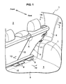
- FiG. 1 is a perspective view schematically showing a vehicle rear body of a vehicle according to the present preferred embodiment.
- a vehicle 1 is, for example, a so-called one box or one volume or hatch type of vehicle, a baggage compartment 4 is provided in back of a seat 3 that is disposed in a vehicle cabin 2.
- the vehicle rear body of the vehicle as apparent from FIG. 1, comprises a vehicle floor portion 5 to at least partly form a floor face of the vehicle and a vehicle sidewall portion 6 to at least partly form a side face of the vehicle body.
- a wheel house 7 is provided at a vehicle sidewall portion 6 so as to project substantially toward the inside of the vehicle 1, and the seat 3 is disposed on the vehicle floor portion 5 via at least one hinge member 8.
- the hinge member 8 is connected to a cross member 10 extending substantially in a vehicle width direction.
- a seat back of the seat 3 comprises a right-side seat back 11 and a left-side seat back 12.
- the right-side seat back 11 will be described mainly.
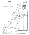
- FIG. 2 is an explanatory sectional view taken along line Y2-Y2 of FIG. 1.
- the seat 3, other parts and the hinge member 8 are shown by two-dotted broken lines in order to show the vehicle sidewall portion 6 apparently.
- the seat 3 comprises a seat cushion 13 and the seat back 11, and the seat back 11 is supported by the hinge member 8 so as to rotate or pivot in a longitudinal direction of the vehicle 1 (i.e. around a rotational or pivotal axis being substantially arranged in width direction) and be biased substantially forward by a biasing member (such as a coil spring) preferably disposed at the hinge member 8.
- a biasing member such as a coil spring
- the hinge member 8 may be disposed below the seat 3 with a different type.
- the seat back 11 can take a specified (predetermined or predeterminable) substantially upright position as shown in FIGS. 1 and 2.
- the seat back 11 is disposed with an inclined angle of about 10 to about 20 degrees relative to a vertical direction.
- the seat back 11 is supported by the hinge member 8 and an outside or lateral end portion of the seat back 11 is supported at the vehicle sidewall portion 6.
- FIG. 3 is a partially-enlarged perspective view of the vehicle rear body, when viewed from a vehicle rear
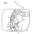
- FIG. 4 is a partially-enlarged perspective view of the vehicle rear body, when viewed from a vehicle front
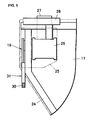
- FIG. 5 is an explanatory elevation view of part of the seat back.
- FIG. 6 is an explanatory sectional view taken along line Y6-Y6 of FIG. 1, which illustrates a state in which the seat 3 is removed.
- a striker 15 is provided at the vehicle sidewall portion 6 near or substantially above the wheel house 7, and the outside end portion of the seat back 11 that is in the specified (predetermined or predeterminable) upright position is supported at the vehicle sidewall portion 6 via the striker 15.
- An elevation view of the striker 15 is illustrated in FIG. 2 and a side view of the striker 15 is illustrated in FIG. 6.
- the striker 15 is formed in a substantially U shape, and its both ends are connected to a striker attaching portion 16 that preferably is formed in a substantially flat-plate shape.
- the striker 15 includes a lateral connecting portion 17 that extends from the striker attaching portion 16 at an angle different from 0° or 180°, preferably at a substantially right angle.
- the striker attaching portion 16 is attached to the vehicle sidewall portion 6 via one or more fastening bolts 18 in such a manner that the lateral connecting portion 17 of the striker 15 extends substantially from the vehicle sidewall portion 6 substantially in the vehicle width direction.
- FIG. 7 is an elevation view of the latch.
- the latch 19 is disposed so as to open rearward, and comprises a first hook portion 21 that includes a slot portion 20 to at least partly receive the above-described lateral connecting portion 17 of the striker 15 and a second hook portion 22 that is coupled to the first hook portion 21 and selectively engages with the lateral connecting portion 17 of the striker 15.
- hook portions 21, 22 are formed in the substantially flat-plate shape and disposed substantially longitudinally (or opening in a longitudinal direction so as to be engageable with the striker, particularly with the striker attaching portion 16) at or near the lateral or outside end portion of the seat back 11, respectively.
- the latch 19 with the first and second hook portions 21, 22 is attached via a panel-shaped attaching bracket 25 to a seat back frame 24 that is provided preferably in a rectangular shape or a reverse-U shape, when viewed from the front, so as to at least partly enclose an outer peripheral portion of the seat back 11, as shown in FIGS. 4 and 5.
- a retractor 26 is provided (directly or indirectly) at or on the attaching bracket 25, and a seatbelt 27 is provided so as to be withdrawn forward from the retractor 26 through a withdrawal portion 28.
- the seat back 11, which preferably is always biased substantially forward, is allowed to rotate or pivot from the front to the rear, and it can be held in the specified (predetermined or predeterminable) substantially upright position by engagement of the latch 19 with the striker 15 provided at or on the vehicle sidewall portion 6, specifically by the first and second hook portions 21, 22 engaging with the lateral connecting portion 17 together vertically.
- the striker 15 is formed to be relatively small compared to the latch 19 as shown in FIG. 2.
- the seat back 11 has a wedge member 31 including a first engagement portion 30 that extends substantially rearward, which is attached at the outside end portion of the seat back 11. And, there is provided a support member 36 including a second engagement portion 35 above the wheel house 7. The second engagement portion 35 is configured to engage with the first engagement portion 30.
- the above-described wedge member 31 comprises a wedge bracket 32 that is attached to the seat back frame 24 preferably so as to extend substantially vertically, and at a lower end of the wedge bracket 32 is provided the first engagement portion 30 preferably substantially having a U-shaped cross section.
- This first engagement portion 30, which is made of a resilient material such as rubber, is disposed such that its curve portion 33 preferably substantially having a U-shaped cross section projects rearward.
- the wedge member 31 is provided substantially below or adjacent to the latch 19 at the outside end portion of the seat back 11. Namely, the wedge member 31 is located such that a distance between the wedge member 31 and the hinge member 8 is shorter than that between the latch 19 and the hinge member 8.
- the support member 36 is attached to or near a forward portion on the wheel house 7.
- the second engagement portion 35 of the support member 36 is attached to an inside portion on the wheel house 7 and includes an opening portion 37 at the front and a wall portion 38 having a substantially U-shaped cross section.
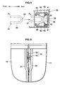
- FIG. 8 is an explanatory elevation view of the second engagement portion, which is a partially-enlarged view of the support member.
- the first engagement portion 30 of the wedge member 31 is illustrated by a two-dotted broken line.
- At both end portions of the wall portion 38 of the second engagement portion 35 are respectively provided one or more rod-shaped axis members 39 extending substantially longitudinally, and respective both ends of the axis members 39 are supported at the wall portion 38.
- Each of the axis members 39 comprises an engaging member 40, a biasing or spring member 41 to bias the engagement member 40 substantially forward, and a plate member 42 that is provided between these members 40, 41.
- the two engaging members 40 which are disposed to substantially face each other, are made of a resilient material such as rubber, and preferably have taper-shaped or converging end faces 43 that are disposed in such a manner that their front ends open widely.
- the first engagement portion 30 provided at the seat back 11 moves from P1 position to P2 position, as shown in FIG. 8, and the curve portion 33 of the first engagement portion 30 is supported by the taper-shaped end faces 43 of the second engagement portion 35. In this way, the first engagement portion 30 pushes the engaging members 40 substantially rearward against the spring or resilient force, so the first engagement portion 30 is fixed substantially in the vehicle width direction by the second engagement portion 35.
- the first engagement portion 30 preferably is configured to have the U-shaped cross section and the second engagement portion 35 preferably is configured to have one or more taper-shaped end faces 43 in the present embodiment.
- any other modifications of the first and second engagement portions 30, 35 can be applied such that the seat back 11 in the upright position and the vehicle sidewall portion 6 can be fixed in the vehicle width direction.
- a wedge-shaped member may be applied so that its front end with taper faces can contact the end faces 43 of the engaging member 40.
- the left-side seat back 12 preferably has the same structure at its outside end portion as the right-side seat back 11 described above.
- the seat 3 can be fixed to the vehicle body surely, vibrations, stresses or shaking that would occur at the vehicle body can be transferred to the seat back with the structure in which there are provided the first engagement portion 30 provided at the outside end portion of the seat back 11 and the second engagement portion 35 provided at the portion of the vehicle sidewall portion 6 corresponding to the first engagement portion 30, and these engagement portions 30, 35 are configured to be fixed in the vehicle width direction when the seat back 11 is in the specified (predetermined or predeterminable) substantially upright position.
- the rigidity of the vehicle body can be improved properly by using the seat back.
- the seat back 11 in the specified (predetermined or predeterminable) substantially upright position is fixed substantially in the vehicle width direction (or a direction at an angle different from 0° or 180°, preferably substantially normal to the longitudinal direction of the vehicle 1 ), it can be prevented from being moved improperly substantially in the vehicle width direction by the vibrations or the like.
- the seat back 11 can be held in the specified (predetermined or predeterminable) substantially upright position surely and the above-described effect can be attained properly. Since the relatively small striker 15 is provided at or on the vehicle sidewall portion 6, a wider space can be provided in the cabin when the seat back 11 is inclined forward or the like.
- the latch 19 includes the first hook 21 and the second hook 22 that are operative to engage with the lateral connecting portion 17 of the striker 15 together substantially vertically, the length of the striker 15 extending inside can be made shorter. Thus, there can be provided the much wider space in the cabin 2 when the seat back 11 is inclined substantially forward or the like.
- first and second engagement portions 30, 35 can engage with each other in a substantially accurate position state or relationship.
- a secure engagement of these portions 30, 35 can be attained along with the engagement of the striker and the latch.
- the wheel house 7 is provided at or on the vehicle sidewall portion 6 so as to project inside and the second engagement portion 35 is provided above or near the wheel house 7, the second engagement portion 35 can be disposed so as to be at least partly hidden by the wheel house 7, and thus better appearances and/or space efficiency can be provided.
- the seat 3 comprises the right-side seat back 11 and the left-side seat back 12 that preferably are separate from each other.
- FIG. 9 is an explanatory diagram schematically showing an enlarged A portion of a seat shown in FIG. 1.
- FIG. 9 illustrates a state in which covering members are removed from the right and left seat backs 11, 12.
- a seat-back connecting device 45 to interconnect the both seat backs 11, 12 is shown in FIG. 9.
- the seat back frame 24 is provided at an outer peripheral portion of the right-side seat back 11, and a right-side connecting member 46 is provided at an inside end portion of the seat back frame 24.
- FIG. 10 is a perspective view of the right-side connecting member provided at the right-side seat back.
- the right-side connecting member 46 comprises a right-side connecting-member attaching portion 47 preferably formed in substantially flat-plate shape, a connecting rod portion 48 projecting from the attaching portion 47 at an angle different from 0° or 180°, preferably substantially at a right angle, and a (preferably substantially disc- or elliptic- or rounded-shaped) hat portion 49 provided at or near a tip of the portion 48.
- the right-side connecting-member attaching portion 47 is attached to or near an upper portion of the inside end portion of the seat back frame 24.
- a left-side connecting member 50 operative to engage with the right-side connecting member 46 provided at the right-side seat back 11.
- the left-side connecting member 50 is (directly or indirectly) attached to the seat back frame 51 provided at an outer peripheral portion of the left-side seat back 12, which can substantially engage with the connecting rod portion 48 of the right-side connecting member 46.
- the seat-back connecting device 45 comprised of the connecting members 46, 50 interconnects the both seat backs 11, 12 via the connecting rod portion 48 in the longitudinal direction in the present embodiment, it may be configured to interconnect them in the vehicle width direction like the wedge member 31 and the support member 36.
- the seat back 3 comprises two independent seat backs, the right-side seat back 11 and the left-side seat back 12, in the present embodiment, it may comprise more seat backs or these right and left seat backs may be formed integrally.
- the seat 3 comprises a plurality of independent seat backs 11, 12 that are disposed substantially side by side substantially in the vehicle width direction and there is provided the seat-back connecting device 45 operative to interconnect adjacent seat backs 11, 12, the seat backs disposed substantially side by side can be interconnected, and thereby the vehicle-body rigidity can be further improved.
- the present invention should not limited to the above-described embodiment, and any other modifications and improvements may be applied within the scope of a sprit of the present invention.
- the present invention is applied to the one-box type of vehicle in the present embodiment, it is also applicable to any other types of vehicle in which the seat back of the seat can engage with the vehicle sidewall portion such as a sedan-type vehicle where the trunk compartment is at least partly separated from the cabin by means of the rear seats and can be made selectively open to the cabin by rotating the seat back substantially forward or by removing it altogether.
Landscapes
- Engineering & Computer Science (AREA)
- Transportation (AREA)
- Mechanical Engineering (AREA)
- Aviation & Aerospace Engineering (AREA)
- Chemical & Material Sciences (AREA)
- Combustion & Propulsion (AREA)
- Seats For Vehicles (AREA)
- Body Structure For Vehicles (AREA)
- Vehicle Step Arrangements And Article Storage (AREA)
Applications Claiming Priority (1)
| Application Number | Priority Date | Filing Date | Title |
|---|---|---|---|
| JP2005287781A JP2007098976A (ja) | 2005-09-30 | 2005-09-30 | シートを備えた車両の車体構造 |
Publications (2)
| Publication Number | Publication Date |
|---|---|
| EP1769966A2 true EP1769966A2 (de) | 2007-04-04 |
| EP1769966A3 EP1769966A3 (de) | 2007-08-01 |
Family
ID=37307093
Family Applications (1)
| Application Number | Title | Priority Date | Filing Date |
|---|---|---|---|
| EP06019391A Withdrawn EP1769966A3 (de) | 2005-09-30 | 2006-09-15 | Rahmenstruktur einer Fahrzeugkarrosserie mit Sitz |
Country Status (4)
| Country | Link |
|---|---|
| US (1) | US20070085368A1 (de) |
| EP (1) | EP1769966A3 (de) |
| JP (1) | JP2007098976A (de) |
| CN (1) | CN1939767A (de) |
Cited By (1)
| Publication number | Priority date | Publication date | Assignee | Title |
|---|---|---|---|---|
| FR2944486A1 (fr) * | 2009-04-21 | 2010-10-22 | Peugeot Citroen Automobiles Sa | Dispositif de verrouillage d'un dossier de siege a la structure d'un vehicule automobile |
Families Citing this family (12)
| Publication number | Priority date | Publication date | Assignee | Title |
|---|---|---|---|---|
| DE102007051718A1 (de) * | 2007-10-30 | 2009-05-20 | GM Global Technology Operations, Inc., Detroit | Kraftfahrzeug mit einer Schiebetür |
| US7762604B1 (en) * | 2009-02-20 | 2010-07-27 | Honda Motor Co., Ltd. | Vehicle seating arrangement |
| IN2012DN03308A (de) * | 2009-10-05 | 2015-10-23 | Johnson Controls Tech Co | |
| US8517460B2 (en) | 2009-10-13 | 2013-08-27 | Honda Motor Co., Ltd. | Vehicle body rear structure |
| JP4886832B2 (ja) * | 2009-10-16 | 2012-02-29 | 本田技研工業株式会社 | ダクトの配設構造 |
| JP5593680B2 (ja) * | 2009-11-12 | 2014-09-24 | マツダ株式会社 | 車両用シート装置 |
| US8360496B2 (en) * | 2010-04-22 | 2013-01-29 | GM Global Technology Operations LLC | Folding seat system |
| US8251429B2 (en) | 2010-07-29 | 2012-08-28 | Honda Motor Co., Ltd. | Striker webbing guide assembly |
| JP5392283B2 (ja) * | 2011-03-14 | 2014-01-22 | トヨタ自動車株式会社 | 車両用シート |
| KR101592758B1 (ko) * | 2014-08-28 | 2016-02-15 | 현대자동차주식회사 | 차량용 후석 시트 리클라이닝 장치 |
| CN113859064B (zh) * | 2021-10-30 | 2023-11-14 | 重庆长安汽车股份有限公司 | 一种汽车后排座椅靠背的解锁结构 |
| JP7361144B2 (ja) * | 2022-01-28 | 2023-10-13 | 本田技研工業株式会社 | 車体後部構造 |
Citations (1)
| Publication number | Priority date | Publication date | Assignee | Title |
|---|---|---|---|---|
| JPH11263247A (ja) | 1998-03-19 | 1999-09-28 | Suzuki Motor Corp | リヤシ−トバック取付構造 |
Family Cites Families (12)
| Publication number | Priority date | Publication date | Assignee | Title |
|---|---|---|---|---|
| US1842373A (en) * | 1929-10-07 | 1932-01-26 | Albert P Ball | Door dovetail |
| US3294443A (en) * | 1965-03-22 | 1966-12-27 | Modern Metal Products Co | Seat back latch |
| DE3045309A1 (de) * | 1980-12-02 | 1982-06-09 | Adam Opel AG, 6090 Rüsselsheim | Ruecksitz fuer kraftfahrzeuge mit einer nach vorne umlegbaren rueckenlehne |
| FR2545766A1 (fr) * | 1983-05-10 | 1984-11-16 | Renault | Mecanisme de verrouillage notamment d'un sommet de dossier de siege sur un element de carrosserie |
| JPH11123966A (ja) * | 1997-10-23 | 1999-05-11 | Ikeda Bussan Co Ltd | シートバックのロック解除構造 |
| JP4296643B2 (ja) * | 1999-07-30 | 2009-07-15 | アイシン精機株式会社 | シートバックロック装置 |
| US6231102B1 (en) * | 1999-10-13 | 2001-05-15 | Honda Giken Kogyo Kabushiki Kaisha | Seat structure in automobile |
| US7118178B2 (en) * | 2002-11-06 | 2006-10-10 | Intier Automotive Inc, | Power folding seat |
| JP4096295B2 (ja) * | 2002-06-18 | 2008-06-04 | スズキ株式会社 | シートストライカのブラケット構造 |
| US6705679B1 (en) * | 2002-09-06 | 2004-03-16 | Fisher Dynamics Corporation | Multi-position latch apparatus and method |
| US6733078B1 (en) * | 2002-12-13 | 2004-05-11 | Fisher Dynamics Corporation | Two-position latch apparatus |
| US7083215B2 (en) * | 2003-09-17 | 2006-08-01 | Toyota Technical Center Usa, Inc. | Double cam locking hinges for folding rear seat |
-
2005
- 2005-09-30 JP JP2005287781A patent/JP2007098976A/ja active Pending
-
2006
- 2006-08-23 US US11/508,193 patent/US20070085368A1/en not_active Abandoned
- 2006-09-15 EP EP06019391A patent/EP1769966A3/de not_active Withdrawn
- 2006-09-28 CN CNA2006101423136A patent/CN1939767A/zh active Pending
Patent Citations (1)
| Publication number | Priority date | Publication date | Assignee | Title |
|---|---|---|---|---|
| JPH11263247A (ja) | 1998-03-19 | 1999-09-28 | Suzuki Motor Corp | リヤシ−トバック取付構造 |
Cited By (1)
| Publication number | Priority date | Publication date | Assignee | Title |
|---|---|---|---|---|
| FR2944486A1 (fr) * | 2009-04-21 | 2010-10-22 | Peugeot Citroen Automobiles Sa | Dispositif de verrouillage d'un dossier de siege a la structure d'un vehicule automobile |
Also Published As
| Publication number | Publication date |
|---|---|
| EP1769966A3 (de) | 2007-08-01 |
| US20070085368A1 (en) | 2007-04-19 |
| JP2007098976A (ja) | 2007-04-19 |
| CN1939767A (zh) | 2007-04-04 |
Similar Documents
| Publication | Publication Date | Title |
|---|---|---|
| CN101384470B (zh) | 车身地板结构 | |
| EP1769966A2 (de) | Rahmenstruktur einer Fahrzeugkarrosserie mit Sitz | |
| US7581793B2 (en) | Vehicle seat | |
| CN103303228B (zh) | 碰撞盒和保险杠装置 | |
| CN104129326A (zh) | 有双锁定就坐位置的车辆座椅组件和调整车辆座椅的方法 | |
| US9630539B2 (en) | Vehicle seats | |
| US8317255B2 (en) | Vehicle seat assembly | |
| EP2322381B1 (de) | Sitzvorrichtung für ein Fahrzeug | |
| US7976093B2 (en) | Cantilevered seat for a vehicle | |
| JP2000238560A (ja) | 自動車のシート | |
| US7300090B2 (en) | Split seat stowage system | |
| US20070057499A1 (en) | Protective device for vehicle occupants | |
| JP5487753B2 (ja) | 車両の後部車体構造 | |
| US6547300B2 (en) | Rear body structure for vehicle | |
| JP4703711B2 (ja) | 自動車用フロアボード構造 | |
| JP7103166B2 (ja) | 車両用シート | |
| JP4892585B2 (ja) | 車両用シート | |
| JP4892586B2 (ja) | シートバックの遠隔操作装置 | |
| JP2006290037A (ja) | シート格納構造 | |
| JP6068413B2 (ja) | シート構造 | |
| CN105522937B (zh) | 车辆用座椅装置 | |
| JP7547142B2 (ja) | 荷室構造 | |
| US6843520B1 (en) | Rear jump seat head restraint mounting sleeve | |
| JP4241278B2 (ja) | シートロック構造 | |
| JP4598579B2 (ja) | 車両用バックトリム |
Legal Events
| Date | Code | Title | Description |
|---|---|---|---|
| PUAI | Public reference made under article 153(3) epc to a published international application that has entered the european phase |
Free format text: ORIGINAL CODE: 0009012 |
|
| AK | Designated contracting states |
Kind code of ref document: A2 Designated state(s): AT BE BG CH CY CZ DE DK EE ES FI FR GB GR HU IE IS IT LI LT LU LV MC NL PL PT RO SE SI SK TR |
|
| AX | Request for extension of the european patent |
Extension state: AL BA HR MK YU |
|
| PUAL | Search report despatched |
Free format text: ORIGINAL CODE: 0009013 |
|
| AK | Designated contracting states |
Kind code of ref document: A3 Designated state(s): AT BE BG CH CY CZ DE DK EE ES FI FR GB GR HU IE IS IT LI LT LU LV MC NL PL PT RO SE SI SK TR |
|
| AX | Request for extension of the european patent |
Extension state: AL BA HR MK YU |
|
| 17P | Request for examination filed |
Effective date: 20080131 |
|
| AKX | Designation fees paid |
Designated state(s): DE |
|
| 17Q | First examination report despatched |
Effective date: 20091016 |
|
| STAA | Information on the status of an ep patent application or granted ep patent |
Free format text: STATUS: THE APPLICATION IS DEEMED TO BE WITHDRAWN |
|
| 18D | Application deemed to be withdrawn |
Effective date: 20100227 |