EP1762374A2 - Procédé et dispositif pour compacter des matériaux en vrac compressibles - Google Patents
Procédé et dispositif pour compacter des matériaux en vrac compressibles Download PDFInfo
- Publication number
- EP1762374A2 EP1762374A2 EP06010814A EP06010814A EP1762374A2 EP 1762374 A2 EP1762374 A2 EP 1762374A2 EP 06010814 A EP06010814 A EP 06010814A EP 06010814 A EP06010814 A EP 06010814A EP 1762374 A2 EP1762374 A2 EP 1762374A2
- Authority
- EP
- European Patent Office
- Prior art keywords
- container
- pressing member
- bulk material
- relative
- section
- Prior art date
- Legal status (The legal status is an assumption and is not a legal conclusion. Google has not performed a legal analysis and makes no representation as to the accuracy of the status listed.)
- Withdrawn
Links
Images


Classifications
-
- B—PERFORMING OPERATIONS; TRANSPORTING
- B30—PRESSES
- B30B—PRESSES IN GENERAL
- B30B9/00—Presses specially adapted for particular purposes
- B30B9/30—Presses specially adapted for particular purposes for baling; Compression boxes therefor
- B30B9/3042—Containers provided with, or connectable to, compactor means
-
- B—PERFORMING OPERATIONS; TRANSPORTING
- B65—CONVEYING; PACKING; STORING; HANDLING THIN OR FILAMENTARY MATERIAL
- B65F—GATHERING OR REMOVAL OF DOMESTIC OR LIKE REFUSE
- B65F3/00—Vehicles particularly adapted for collecting refuse
- B65F3/14—Vehicles particularly adapted for collecting refuse with devices for charging, distributing or compressing refuse in the interior of the tank of a refuse vehicle
Definitions
- the invention relates to a device for compressing compressible bulk material, in particular waste, with at least one container for receiving the bulk material and with at least one pressing member, which for performing compression strokes in at least one direction of movement with a vertical direction component under engagement in the container back and forth displaced is.
- the invention further relates to a method, which can be carried out in particular by means of such a device, for compacting bulk material, in particular waste, arranged in at least one container by means of at least one pressing member, the pressing member for performing compaction strokes in at least one direction of movement with a vertical direction component under engagement the container is shifted back and forth to compress the bulk material.
- rollers For compacting bulk material in the form of refuse, rollers are known, for example, which are arranged on a carrying device and can be lowered into a container for receiving the waste ( DE 34 06 879 A1 . DE 39 03 642 A1 ). In this case, the roller is moved by means of the support device over the cross section of the container, wherein the garbage therein herein is compressed solely due to the weight of the roller and possibly applying an additional contact pressure on the roller.
- a disadvantage is the one hand, that such rollers are relatively expensive due to their considerable mass and require a corresponding dimensioning of the storage and the support device.
- the pressing member is in turn formed by a roller, which is mounted on a holding device which engages over the container for receiving the bulk material, in order, on the one hand, to move it over the cross section of the container while compressing the bulk material and, on the other hand, to sink it into the container or to lift it out of it.
- the above applies in connection with the press rolls according to the DE 34 06 879 A1 and DE 39 03 642 A1 said.
- the DE 42 37 143 A1 describes a compacting device of refuse, which is detachably coupled to a refuse container.
- the compacting device comprises a pivotally mounted pressure plate whose cross-section corresponds approximately to the free opening cross-section of the refuse container and that cross-section of the refuse container, which serves as the abutment compacted by the press plate waste.
- the disadvantage is on the one hand that the compacting device and the refuse container must have coordinated shapes and thus a configured in a certain way compacting device can not be used for different containers.
- DE 39 26 866 A1 and DE 93 14 726 U1 Devices are removable, which comprise a dimensionally stable container with a container, vertically - manually or by means of a press - vertically displaceable press ram associated, the cross-section substantially corresponds to the free cross section of the container.
- the ram is mounted vertically displaceable either on a container lid or on a support structure, below which the container is arranged.
- a press ram has the advantage that it is not only lighter and more cost-effective, but in particular due to the fact that it is capable of dynamic compression strokes, a compression of the bulk material which is more effective than static pressing by means of rollers guaranteed.
- the invention has the object of developing a device and a method of the type mentioned in that while avoiding the aforementioned disadvantages in a simple and cost effective manner effective compression of compressible bulk material using a largely arbitrarily configured container is possible.
- this object is achieved in a device of the aforementioned Art solved in that the maximum cross section of the pressing member is at most 50% of the free cross section of the container and that the pressing member and the container in a substantially horizontally disposed x, y plane in both the x-direction and in the y-direction relative to each other are relocatable.
- the invention provides for a feasible in particular by means of such a device method of the type mentioned above, that a pressing member is used, the maximum cross section is at most 50% of the free cross section of the container and that the pressing member and the container in a substantially horizontally disposed x, y plane are displaced relative to each other in both the x-direction and in the y-direction.
- the invention enables a highly effective compression of compressible bulk material, such as garbage, wherein the compacting device and the garbage container need not have matched shapes, but only care must be taken that the maximum cross section of the pressing member at most 50%, preferably at most 40% , most preferably at most 30% and in particular at most 20% of the free cross section of the container. It has proved to be particularly advantageous if the maximum cross section of the pressing member is at most 10%, in particular between about 1% and about 10%, for example between about 3% and about 7%, of the free cross section of the container. In this way, in a sufficiently small configuration of the pressing member practically any container can be used, such as stationary or already arranged on railway cars or trucks containers with solid floors or moving floors, fixed mounted on trucks or trailers container or conveyor belts, etc.
- the present invention possible displacement of the pressing member in a substantially horizontally disposed plane in both the x and y direction, ie to a virtually arbitrary point on this level within the free cross section of the container, ensures complete compression of the bulk material in the container at any location by the pressing member formed eg in the form of a stamp is moved under multiple compression strokes over the entire cross-section of the container.
- compressible bulk material in particular garbage, dynamically compressed by at least one pressing member by the pressing member for performing compression strokes in at least one direction of movement with a vertical direction component under engagement in the container is shifted back and forth to compress the bulk material, and a pressing member is used whose maximum cross section is at most 50%, preferably at most 40%, most preferably at most 30%, in particular at most 20% and particularly preferably at most 10%, for example between about 1% and about 10%, as between about 3% and about 7% of the free cross-section of the container is so by displacement of the pressing member and the container in a substantially horizontally disposed x, y plane in both the x-direction and in the y-direction relative to each other with the application of relatively small Pressing achieved a very effective compression of the bulk material.
- the pressing member and the container are expediently displaced relative to one another in such a way that the pressing member is moved at least once or preferably several times into each cross-sectional region of the container in order to carry out at least one compression stroke there.
- the individual compression strokes of the pressing member are set at a distance from each other, which is less than the cross section of the pressing member in approximately horizontal displacement direction of the same in the x, y plane, so that in a compression stroke again a part of the range , which has been compressed by the previous compression stroke is recompressed.
- there are no limits to the sequence of the compression strokes on different regions of the container They are primarily based on the type of bulk material to be compressed and on the desired degree of compaction.
- the pressing member is expediently formed by a ram, which - as explained in more detail below in connection with the drawings - not necessarily be formed flat, but depending on the application, e.g. can also be equipped with a profiled or contoured pressing surface.
- the pressing member and / or the container substantially can be moved linearly in the x and / or in the y direction. It is expedient, although not necessary, that the x, y plane of the relative movement between the pressing member and the container spanning coordinates x and y are arranged approximately at right angles to each other, so that the pressing member and the container in two mutually perpendicular, essentially horizontal spatial directions are movable relative to each other.
- back and forth movable pressing member for compressing the bulk material in the substantially horizontal x, y plane in both the x-direction and in the y-direction movable and the container at least during the compression of the bulk material - is arranged substantially stationary. This can be done for example by means arranged on a support structure guides on which the pressing member is guided displaceably in the x and y directions.
- the pressing member can be stored substantially stationary and the container in the substantially horizontal x, y plane in both the x-direction and in the y-direction to be movable, which, for example, by means of a movable in the x and y-direction platform can take place, which carries the container - whether in the form of a container, a truck or the like.
- the container is displaceable only in the x-direction (or only in the y-direction), while the pressing member is displaceable only in the y-direction (or only in the x-direction).
- the pressing member and / or the container - preferably substantially linearly - be moved in the x and / or in the y direction.
- the pressing member and / or the container rotatable about at least one substantially vertical axis and / or substantially linear in the x and / or y direction is / is movable. It is / are therefore the pressing member and / or the container rotated about at least one substantially vertical axis and / or substantially linear in the x and / or y-direction, so that the relative displacement between the pressing member and the container in the x, y plane in particular from a rotational movement and a - preferably linear - translational movement composed.
- the axis in particular substantially linear, is arranged to be movable. Consequently, the pressing member (or the container) on the one hand to rotate about the substantially vertical axis and can this axis on the other hand moved translationally, which can be done for example by a arranged on a guide axis of rotation, while the container (or the pressing member) at least during the compaction of the bulk material is stationary.
- An alternative embodiment provides in such a case that the axis is arranged stationary. If the axis is thus kept stationary, then for example the pressing member (or the container) can be rotated about the stationary axis and the container (or the pressing member) can be moved translationally, so that the relative movement of the pressing member with respect to the container in the x, y In turn, plane composed of a movement of both the pressing member and the container, wherein one of these movements is translational and the other of these movements is rotating.
- the pressing member and / or the container in the case of a stationary axis of rotation of the container or of the pressing member, it is possible for the pressing member and / or the container to be displaceable, preferably substantially linearly, in the radial direction of the axis. This can be done, for example, by means of a Be ensured radial direction of the axis of rotation extending guide on which the pressing member or the container is guided. In this way, the pressing member and / or the container, preferably in a substantially linear, is displaced in the radial direction of the axis.
- the superimposition of a rotary movement with a translational movement may in principle be advantageous, in particular in the case of a container with an approximately round or oval cross-section, but of course it is also conceivable in the case of a container with an angular cross-sectional profile.
- the pressing member is pivotally mounted.
- the pressing member is not only able to carry out a substantially vertical compression stroke, but can be pivoted into and out of the container during the displacement into and out of the container in order to convey the bulk material also by means of compression strokes inclined with respect to the vertical, e.g. in the direction of the lateral walls of the container, to compress.
- a load cycle of a compression stroke of the pressing member may, depending on the application, preferably for a duration between about 1 s and about 30 s, e.g. between about 1 s and about 10 s, be adjustable.
- the pressing member is associated with a feeding device for applying bulk material into the container.
- the feeder may be formed, for example, of belt conveyors, screw conveyors, bucket elevators, fluidic, such as hydraulic or pneumatic conveyors, material slides or the like and operate continuously, semicontinuously or discontinuously.
- a delivery point of the feed device via which the bulk material can be transferred into the container, preferably displaceable relative to the container and / or relative to the pressing member, so that it is possible, the discharge point of the bulk material into the container relative to the container and / or relocate relative to the pressing member.
- the bulk material may thus e.g. be placed at one of the current position of the pressing member spaced position in the container, so that the container filled at one point and the already placed in the container bulk material can be compacted at another point.
- several containers can be filled on the one hand and on the other hand compacted. In both cases results in a very fast and thus economical filling / compaction of the bulk material.
- the discharge point for the bulk material may in turn be arranged in at least one horizontal direction - e.g. be substantially linear - movable and / or be rotatable about a substantially vertical axis.
- the container and / or the feeder is associated with a weighing device in order to avoid overloading of the container or a vehicle carrying this.
- the bulk material placed in the container can be weighed in this way before, during or after the transfer into the container, in particular substantially continuously, wherein the weighing device preferably cooperates with a control of the feeder that prevented upon reaching a programmable maximum weight any further supply of bulk material into the container becomes.
- the device according to the invention has at least one sensor which is used for scanning the relative position of the container with respect to the pressing member and / or with respect to a support or a supporting structure of the pressing member and / or for scanning the filling level of the bulk material at the respective position is trained.
- the relative position of Container with respect to the pressing member and / or with respect to a carrier of the pressing member are detected by sensors.
- the pressing member can be targeted in this way to such a region of the container to move relative to this, at which the filling height of the bulk material requires a compression and / or displacement to adjacent areas.
- a development of the invention provides that the container and / or the pressing member is elastically, in particular by means of springs, stored / are to be able to support the compression of the bulk material by means of vibration of the container or of the pressing member.
- the springs of such a bearing can in this context practically arbitrarily, for example of coil springs, fluid springs or the like, be formed.
- the resilient mounting of the container and / or the pressing member is associated with a drive which is designed to enable the container or the pressing member in forced oscillations. With “forced vibrations" vibrations are addressed in this context, which not only from the compression strokes of the pressing member, but - optionally in addition to this - caused by the drive of the resilient mounting.
- these vibrations do not necessarily have to be vertical, but may alternatively or additionally also be horizontal or oblique upward / downward.
- the drive may be formed for example by an imbalance drive, which of course any other known means are conceivable, which are suitable to enable the container and / or the pressing member to vibrate.
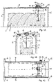
- a first embodiment of an inventive device for compressing compressible bulk material 1, such as garbage reproduced comprises a container 2 for receiving the bulk material 1, which is designed in particular as a transportable container and interchangeable, so that it transported away after compressing bulk material therein and by a new, e.g. empty or filled with not yet compressed bulk material container can be replaced.
- the container 2 may be e.g. to act a common standard container with a substantially rectangular free cross section and with a length of about 12 m and a width of about 2.40 m.
- the apparatus further comprises a pressing member in the form of a ram 3, which in the present embodiment in the direction indicated by the arrow 4 (Fig. 1A and 1B) vertical direction for performing compression strokes back and forth, as described below with reference to FIG 16 to 22 is explained in more detail.
- a pressing member in the form of a ram 3, which in the present embodiment in the direction indicated by the arrow 4 (Fig. 1A and 1B) vertical direction for performing compression strokes back and forth, as described below with reference to FIG 16 to 22 is explained in more detail.
- the cross section of the ram 3 is substantially smaller than the free cross section of the container 2 and in the present embodiment, for example, between about one half and about one square meter, ie about 3% to 7% of the free cross section of the container 1.
- a load cycle of the compression stroke depending on the bulk material to be compacted 1 and depending on the actuating means used the press ram 3, for example, about 10 s to 30 s.
- pneumatic cylinders are used to actuate the press ram 3 (see below with reference to Figures 16 and 17)
- shorter compression strokes up to a few seconds for example between about 1 s and about 10 s, are also possible, if desired.
- the support structure 5 has a plurality of supports 6, here four arranged in the region of the corners of the container 2 supports 6, which carry two, for example, in the longitudinal direction of the container 2 above the same extending guide rails 7.
- a carriage 8 on which the press ram 3 is arranged to be displaceable in the vertical direction 4, is guided in a linearly displaceable manner in the longitudinal direction of the container 2 (arrow 10 of FIG. 1C).
- the carriage 8 is guided linearly displaceably along the guide rails 7 and between these extending guide rails 9 in the transverse direction of the container (arrow 11 of FIG. 1C).
- the guides formed by the guide rails 7 as well as by the guide rails 9 thus tension a vertical, horizontal x, y plane with respect to the vertical displaceability of the press ram 3 (arrow 4) on, wherein the ram 3 in two mutually perpendicular directions x and y (arrows 10 and 11) of this plane relative to the container 2 is displaced to compress the bulk material 1 at any area of the container 2.
- drive rollers 12 of the carriage 8 over which this along the transversely extending guide rails 9 is displaceable, and not shown drive rollers 13, via which the guide rails 9 formed by the guide along the longitudinal direction extending guide rails 7 is displaced.
- electric motors can be provided to drive each motors 14, 15, for example.
- the guides formed by the guide rails 7 and 9 in the horizontal x, y plane need not necessarily extend perpendicular to each other nor have to have a linear course. However, you should ensure that the ram 3 is so displaced relative to the container 2 that it is able to penetrate into any area of the container 2.
- FIGS. 2A to 2C differs from the device according to FIGS. 1A to 1C primarily in that the relative displacement between the container 2 and the - in the present case in the vertical direction 4 and her displaceable - ram 3 is done by the container 2 in a horizontal x, y plane displaced and the ram 3 is arranged stationary on the support structure 5.
- the container 2 can be erected on a first - upper - platform 20, which is equipped with drive rollers 21, which are guided along a second - lower - platform 22 provided guide 23.
- the guide 23 (see in particular Fig. 2C) extends, for example, in the transverse direction (arrow 24 of Fig. 2B) of the container 2.
- the second - lower - platform 22 is in turn equipped with drive rollers 25 which in an example provided on the ground below the support structure 5 guide 26 (see in particular Fig. 2C) are guided, wherein the guide 26 of the lower platform 22 in the present embodiment again - although not necessarily - perpendicular to the guide 23 of the upper platform 20, that is approximately in the longitudinal direction of the container 2, is arranged and as well the latter extends substantially linearly, so that the lower platform 22 in the longitudinal direction (arrow 27 of Fig. 2A) of the container 2 is displaceable.
- the guides 23, 26 of the platforms 20, 22 thus tension a horizontal x, y plane along which the container 2 can be moved relative to the - here stationary - ram 3, so that it moves to any area of the container 2 can be to compact the bulk material 1 located there.
- the displaceability of the container 2 relative to the ram 3 is effected by both the container 2 and the ram 3 - for example, substantially perpendicular to each other - are displaced.
- the ram 3 is similar to the embodiment of FIGS. 1A to 1C on a carriage 8 a, which along two longitudinally of the container 2 extending from the supports 6 supported guide rails 7 is driven by driven by a motor 15 drive rollers 13 (arrow 10).
- the ram 3 is in the present case, however, firmly fixed to the between the guide rails 7 extending slide 8a back and forth displaced (arrow 4), while the container 2 on a with drive rollers 21 equipped platform 20 is set up.
- the drive rollers 21 of the platform 20 are along perpendicular to the guide rails 7 of the carriage 8a of the press ram 3 extending guides 23 movable (arrow 24), the latter can be configured in accordance with the guides 23 of FIG. 2A to 2C substantially.
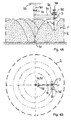
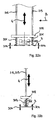
- FIGS. 4A to 4B show an embodiment of a device according to the invention for compressing compressible bulk material 1, in which the relative displacement between the ram 3 and the container 2 in an approximately horizontal x, y plane is effected by a rotational movement with a translational, to Rotary axis of the rotary motion radial displacement is combined.
- the container 2- here essentially circular-cylindrical-is arranged stationarily on the floor.
- the ram 3 is first about a stationary shaft formed by a vertical shaft 31 rotatable (arrow 32), wherein the axis 31 is suitably aligned with the center of the container 2.
- the shaft 30 may be fixed in the region of its upper, the container 2 facing away from the end, for example, on a not shown in FIGS. 4A and 4B supporting structure 33 which engages over the container 2.
- the shaft 30 is rotatably supported about the axis 31 via a rotary drive also not shown on the support structure 33.
- a guide 34 Extends in the area of its lower end itself from the shaft 30, a guide 34 radially outwardly, with a drive rollers 36 equipped with carriage 35, to which the ram 3 is vertically displaced back and forth (arrow 4 of Fig. 4A), along this guide 34 radially - in the present Case linear - movable (arrow 37).
- the guide 34 projects preferably approximately from the shaft 30 to the edge of the container 2 radially outward in order to move the ram 3 approximately within the entire free cross section of the container 2 relative to this.
- guide 34 biases a horizontal x, y plane along which the ram 3 relative to the container 2 can be moved so that the ram 3 can be moved to any area of the container 2 to compact the bulk material 1 located there.
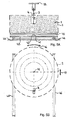
- FIGS. 5A to 5B operates on the same principle as the embodiment according to FIGS. 4A to 4B, but differs therefrom in particular in that the vertically displaceable press ram 3 (arrow 4 of FIG. 5A) is stationary on the Supporting structure 33 is mounted, while the container 2 is displaceable relative thereto.
- the container 2 is placed on a first - upper - platform 40, which is rotatable about a central shaft 41 about an axis 42.
- the axis 42 is also translational - linear in the present case - moved by the arranged on the underside of the upper platform 40 shaft at its upper platform remote from the lower end to a second - lower - platform 43 is arranged, which provided with drive rollers 44 which is guided along guides 45 (Fig.
- the rotation of the platforms 40, 43 happens, for example, characterized in that the shaft 41 rotatably connected to one of the platforms 40, 43 and by means of a rotary drive (not shown) with respect to the other platform 43, 40 in the direction of arrow 46 can be rotated.
- the axle 42a is stationary and, for example, mounted on the bottom at its lower end via a rotary drive (not shown) and fixed at its upper end in a rotationally fixed manner to the center of the platform 40a on its underside, so that the platform 40a with the container 2 carried by it is freely rotatable about the stationary axis 42a.
- the ram 3 is - for example, in a similar manner as in the embodiment of FIGS. 3A to 3C the case is - attached to a carriage 8a, which is translationally guided along parallel guide rails 7, which in turn are supported by the supports 6 of the support structure 4.
- the drive of the carriage 8a of the ram 3 is done via a motor 15 driven.
- FIGS. 7A to 7B and FIGS. 8A to 8B show embodiments of devices according to the invention for compressing compressible bulk material 1, in which the press ram 3 is not only displaceable vertically back and forth, but is also pivotably mounted about a horizontal axis.
- the embodiment shown in FIGS. 7A and 7B is essentially based on the principle of the embodiment described above with reference to FIGS. 1A to 1C and differs therefrom primarily in that the press ram 3 is attached to the guide rail 7 in the longitudinal direction of the guide rail 7.
- the container 2 is pivotable about an axis 50 (see arrow 51), the axis 50 extending in the longitudinal direction of the container 2.
- a further guide 9 (see Figures 1A to 1C) extending perpendicularly to the guide rails 7 can be dispensed with, since, owing to the pivotability of the press ram 3 in the direction of the arrow 51, it is ensured that the press ram becomes an arbitrary cross-sectional area of the container 2 can be shifted towards to compress the bulk material 1 located there.
- the approximately horizontal x, y plane in which the ram 3 relative to the container 2 is displaced, is thus determined by the guide rails 7 of the carriage 8a of the ram 3 in connection with the pivot axis 50 of the ram 3.
- FIGS. 8A and 8B is based essentially on the principle of the embodiment explained above with reference to FIGS. 3A to 3C, in which the relative displacement of the press ram 3 with respect to the container 2 on the one hand by a displacement of the platform 20 with the container along the guides 23 in the direction of the arrow 24 and on the other hand by a displacement of the carriage 8a with the ram 3 along the guide rails 7 in the direction of the arrow 10.
- the embodiment shown in FIGS. 8A and 8B represents a further development of the invention in comparison with the embodiment according to FIGS. 3A to 3C in that the press ram 3 is pivotably mounted there on the carriage 8a about a horizontal axis 60 in the direction of the arrow 61.
- the pivot axis 60 of the ram 3 in contrast to the embodiment shown in FIGS. 7A and 7B, is e.g. arranged in the transverse direction of the container 2 carried by the platform 20.
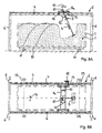
- FIGS. 9A to 9D again show an embodiment of a device according to the invention for compressing compressible bulk material 1 corresponding to FIGS. 1A to 1C, which is further equipped with a feed device 70, via which the bulk material 1 can be transferred into the container 2.
- the feeder 70 has an example in the longitudinal direction of the container 2 extending conveyor belt 71 which is fixed to a further carriage 72 which - as well as the carriage 8 with the ram 3 - along the guide rails 7 in the longitudinal direction of the container 2 is displaceable (see, in particular Fig. 9A, Arrow 75).
- the carriage 72 carrying the conveyor belt 71 is provided with drive rollers 73, which are driven by a motor 74, such as an electric motor.
- the conveyor belt 71 transversely to the guide rails 7 is displaced (not shown), which can also be done for example by means of electric motors.
- the hopper 76 is arranged at such a position that it opens in any relative position of the displaceable along the guide rails 7 conveyor belt 72 relative to the container 2 and / or relative to the carriage 8 with the ram 3 in the conveyor belt 72.
- a discharge point 80 of the feeder 70 is set, via which the bulk material 1 is transferred into the container 2 and falls into it.
- the conveyor 70 is further associated with a weighing device 90 in the form of a belt weigher (see in particular Fig.
- the weighing device 90 is preferably designed for the continuous weighing of the mass flow of the bulk material 1 passing through it, so that an overloading of the container 2, as in particular in the case of a container permanently or detachably connected to a truck (not shown in FIGS. 9A to 9D), is reliable must be excluded is avoided.
- sensors S 1 , S 2 may be provided, which for scanning the relative positions of the ram 3 and / or the feeder 70 with respect of the container 2 or of the bulk material 1 located therein, in order to be able to displace the press ram 2 and / or the feed device as a function thereof to a respectively suitable position relative to the container 2.
- FIG. 9D shows a view corresponding to FIG. 9A of the same embodiment of a device according to the invention for compacting compressible bulk material 1, wherein a schematic block diagram of a programmable controller 100 of the device is indicated.
- the controller 100 includes a microprocessor 101, in which a plurality of programmable parameters, such as the container volume V, the maximum compression force F max of the ram 3, the maximum filling amount m max of the container 2, the speed V R of the relative displacement of ram 3 and / or feeder 70 with respect to the container 2 and optionally other parameters, such as the height H v and / or the time T v of a compression stroke of the press ram 3, etc., can be entered.
- a plurality of programmable parameters such as the container volume V, the maximum compression force F max of the ram 3, the maximum filling amount m max of the container 2, the speed V R of the relative displacement of ram 3 and / or feeder 70 with respect to the container 2 and optionally other parameters, such as the height H v and
- a plurality of parameters that can be detected by sensors such as the material flow M 'of the bulk material 1 measured by the weighing device 90, that of the sensors S 1 , S 2 at the respective Relative position of ram 3 or feeder 70 and container 2 detected filling height H S of the bulk material 1, etc.
- the microprocessor 101 calculates from the parameters mentioned a suitable operation, which, for example, the control of the displacement s z of the feeder 70 along the guide rails 7, the displacement S p of the ram 3 along the guides 7 and 9, the compression stroke s V and / or Compression force F V of the press ram 3, etc. includes.
- a suitable operation which, for example, the control of the displacement s z of the feeder 70 along the guide rails 7, the displacement S p of the ram 3 along the guides 7 and 9, the compression stroke s V and / or Compression force F V of the press ram 3, etc. includes.
- a suitable operation which, for example, the control of the displacement s z of the feeder 70 along the guide
- FIGS. 10A to 10C and 11A to 11C each show an apparatus for compressing bulk material 1, which differs from the apparatus according to FIGS. 2A to 2C or 3A to 3C in each case due to the additional presence of a feed device 70 whose feeding device (eg in the form of a hopper 76, see Fig. 9A to 9D) is not shown again.
- a feed device 70 whose feeding device (eg in the form of a hopper 76, see Fig. 9A to 9D) is not shown again.
- the same applies to an optionally provided weighing device 90 cf. also FIGS. 9A to 9D).
- FIGS. 9A to 9D In the case of the apparatus shown in FIGS.
- the conveyor 70 can be arranged stationary according to the ram 3, or it is - in the longitudinal direction of the container 2 (arrow 75) - with respect to the press ram 3 displaced, which can be done analogously to the device of FIG. 9A to 9D, characterized in that its conveyor belt 71 is slidably guided along a guide by means of a carriage. This also applies to the device shown in FIGS. 11A to 11C, their conveying device 70 here by means of the carriage 72 in the direction of the arrow 75 is displaced.
- FIGS. 12A to 12B again show an embodiment of a device according to the invention for compacting compressible bulk material 1 corresponding to FIGS. 4A to 4B, which is in turn equipped with a feed device 70, via which the bulk material 1 can be transferred into the container 2.
- the guide 34 arranged on the shaft 30 and rotatable about the stationary axis 31 extends substantially over the entire diameter of the container 2 and is provided on the guide 34 in addition to the carriage 35 on which the press ram 3 is fixed vertically displaceable back and forth (arrow 4 of FIG. 12A), a feeding device 70 out.
- the feed device 70 in turn, essentially corresponds to that according to FIGS. 9A to 9D.
- a conveyor belt 71 extending along the guide 34, which is rotatable about the axis 31, of the carriage 35 of the press ram 3, which is fastened to a further carriage 72, which is displaceable along the rails of the guide 34 (compare, in particular, FIG ).
- the carriage 72 carrying the conveyor belt 71 is equipped with drive rollers 73, which are driven by a motor 74.
- a hopper 76 for example, stationary on the guide 34 - arranged to give the bulk material 1 the conveyor belt 72 can (arrow 77).
- the hopper 76 is arranged at such a position that it opens in any relative position of the displaceable along the guide conveyor belt 72 72 relative to the container 2 and / or relative to the carriage 35 with the ram 3 in the conveyor belt 72.
- a discharge point 80 of the conveyor 70 is set, via which the bulk material 1 is transferred into the container 2 and falls into it.
- the conveying device 70 and / or the container 2 can furthermore be assigned a weighing device 90, not shown in FIGS. 12A and 12B, which can be configured, for example, similarly to the weighing device 90 according to FIGS. 9A to 9D.
- FIGS. 13A and 13B, 14A and 14B and FIGS. 15A and 15B respectively show a device which is different from the device according to FIGS. 5A and 5B, 6A and 6B or 7A and 7B due to the additional presence of a feed device 70 different. Due to the fact that the container 2 of the device according to FIGS. 13A and 13B can be displaced both translationally (arrow 47) and rotationally (arrow 46), the feed device 70 can be stationary in this case, if desired, but also with respect to the stationary mounted press ram be displaced (eg in the extension direction of the left in Fig. 13B guide rail 45). In the apparatus according to FIGS.
- actuation means of the ram 3 are shown in order to shift this with a / preferably compressible compression force or Verdichtungshub in a substantially vertical direction back and forth.
- a / preferably compressible compression force or Verdichtungshub in a substantially vertical direction back and forth.
- a pair of piston / cylinder units 110, 111 are provided, the cylinders of which are fixed directly to the supporting structure 5 or to a carriage (not shown) displaceable thereon and whose piston rods are fixed to the upper side of the ram 3 ,
- the piston / cylinder units 110, 111 may be e.g. be operated pneumatically, hydraulically or hydropneumatically using suitable pressure fluids.
- two pairs of piston / cylinder units 112, 113; 114, 155 are provided, of which the cylinders of the outer pair 112, 113 are fixed directly to the supporting structure 5 or to a carriage (not shown) displaceable thereon and whose piston rods are fastened to a cross member 115 connecting them.
- the cylinders of the inner pair 114, 115 are further set of piston / cylinder units, while the piston rods are fixed to the upper side of the ram 3.
- the piston / cylinder units 112, 113; 114, 115 may in turn be operated eg pneumatically, hydraulically or hydropneumatically using suitable pressure fluids.
- a scissor lever gear 117 disposed between the ram 3 and the support structure 5 or a carriage (not shown) disposed thereon, e.g. by means of piston / cylinder units or otherwise actuated.
- threaded spindles 118; 119, 120 possible, at the lower end of the ram 3 is fixed and which - by means of a drive motor 121; 122 actuated - are mounted on the support structure 5 or a movable thereto slide (not shown). While in many cases a single threaded spindle 118 is sufficient ( Figure 19), two or more threaded spindles 119, 120 may also be provided ( Figure 20), e.g. are driven synchronously by the motor 122.
- FIG. 21 shows a linear drive 123, which comprises a chain or belt drive 124 which extends over driven deflection rollers and to which a rod 125 connected to the press ram 3 is fastened in a vertically displaceable manner.
- a linear drive 123 which comprises a chain or belt drive 124 which extends over driven deflection rollers and to which a rod 125 connected to the press ram 3 is fastened in a vertically displaceable manner.
- FIGS. 22A and 22B show a development of an actuating device of the press ram 3, in which latter, for example by means of helical springs 201, is mounted elastically on a rigid support plate 202 arranged above it.
- the support plate 202 is - in the present case by means of a pair of piston / cylinder units 212, 213 - guided substantially vertically displaceable back and forth, so that the punch 3 is able to perform in the direction of arrow 4 compression strokes.
- the resilient mounting of the ram 3 is a drive 203, for example in the form of an imbalance drive assigned, which is attached to the top of the ram 3 and is capable of the ram 3 to set in forced oscillations, as indicated by the arrows 204 is.
- the pressing ram 3 is set by means of the drive 203 with respect to its compression strokes higher - preferably significantly higher - frequency oscillated.
- the container can be mounted elastically and optionally displaceable in forced oscillations (not shown).
- a resiliently mounted and optionally by means of a suitable drive 203 as shown schematically in Fig. 22A and 22B unbalance drive, displaceable in Zwangsschwingungen press punches 3 course in conjunction with the embodiments of the device according to the invention shown in FIG to 15 and 27 to 29, as well as in connection with the shown in Fig. 16 to 21 controls the press ram 3 and in conjunction with the reproduced in Fig. 23 to 26 forms of the press ram 3 itself can be used.
- Fig. 23 shows a punch die 3 tapering down to a point, which may, for example, have a round (Fig. 23A), rectangular (Fig. 23B) or square cross-section (Fig. 23C).
- Fig. 24 is a blunt down to press punches 3 to which has, for example, a round (FIG. 24A) or rectangular cross-section (FIG. 24B).
- FIG. 25 shows a press stamp 3 which is flat on the underside and is chamfered outwards, which has, for example, a rectangular cross section with only narrow side chamfer (FIG.
- Fig. 26 is provided with two downwardly projecting edges or tips arranged at opposite ends and formed, for example, with a rectangular (Fig. 26A) or round cross-section (Fig. 26B).
- Fig. 26A a rectangular
- Fig. 26B a round cross-section
- the container (s) 2 can also be arranged on a vehicle, such as a truck, whereby the container 2 of the truck can be filled directly with bulk material 1 and the latter can then be compacted. can, or a container 2 is filled, while the bulk material of the other - already filled - container 2 is compressed.
- sensors S 1 , S 2 can serve to detect the position of the container 2 and / or detect an imminent collision of the container 2 with parts of the truck early and - if they are for example operatively connected to a warning device - prevent.
- FIGS. 28A to 28C which is likewise shown there during filling and compression of the filled bulk material 1 in a container 2 arranged on a truck, instead of a feed hopper 76 of the feed hopper 76 arranged stationary on the supporting structure, as shown in FIG 9A to 9D is provided, a laterally opening into the conveyor belt 71 of the feeder 70 conveyor belt 130 is provided which via a Feed hopper 76a can be equipped with bulk material. Otherwise, the apparatus shown in FIGS. 28A to 28C largely corresponds to that shown in FIGS. 9A to 9D.
- FIGS. 29A to 29C show a device, also largely similar to the device according to FIGS. 9A to 9D, in an operating state as shown in FIGS. 28A to 28C.
- the apparatus of Figs. 29A to 29C differs from that of Figs. 9A to 9D primarily in that the feeder 70 is replaced with the hopper 76 (Figs. 9A to 9D) with a fluidic, e.g. pneumatic gripper unit 140 is equipped, via which the conveyor belt 71 of the feeder 70 can be acted upon with bulk material 1, before the latter passes via the conveyor belt 71 into the container 2.
Priority Applications (1)
| Application Number | Priority Date | Filing Date | Title |
|---|---|---|---|
| EP07005745A EP1859925A1 (fr) | 2006-05-26 | 2007-03-21 | Dispositif destiné à comprimer des produits en vrac comprimables |
Applications Claiming Priority (1)
| Application Number | Priority Date | Filing Date | Title |
|---|---|---|---|
| DE200520014307 DE202005014307U1 (de) | 2005-09-10 | 2005-09-10 | Vorrichtung zum Verdichten von komprimierbarem Schüttgut |
Publications (2)
| Publication Number | Publication Date |
|---|---|
| EP1762374A2 true EP1762374A2 (fr) | 2007-03-14 |
| EP1762374A3 EP1762374A3 (fr) | 2007-10-31 |
Family
ID=37295748
Family Applications (1)
| Application Number | Title | Priority Date | Filing Date |
|---|---|---|---|
| EP06010814A Withdrawn EP1762374A3 (fr) | 2005-09-10 | 2006-05-26 | Procédé et dispositif pour compacter des matériaux en vrac compressibles |
Country Status (2)
| Country | Link |
|---|---|
| EP (1) | EP1762374A3 (fr) |
| DE (1) | DE202005014307U1 (fr) |
Cited By (1)
| Publication number | Priority date | Publication date | Assignee | Title |
|---|---|---|---|---|
| DE202007010997U1 (de) | 2007-08-07 | 2008-09-11 | Hagemann, Andreas, Dipl.-Ing. (FH) | Vorrichtung zum Verdichten von komprimierbarem Schüttgut und Preßorgan einer solchen Vorrichtung |
Citations (8)
| Publication number | Priority date | Publication date | Assignee | Title |
|---|---|---|---|---|
| DE8228963U1 (de) | 1982-10-15 | 1984-03-08 | Bergmann, Heinz, 4474 Lathen | Vorrichtung zum verdichten von aus verpackungsmaterial und leicht pressbaren abfaellen bestehendem muell |
| DE3406879A1 (de) | 1984-02-25 | 1985-08-29 | Heinz 4474 Lathen Bergmann | Vorrichtung zum verdichten von aus verpackungsmaterial und leicht pressbaren abfaellen bestehendem muell |
| DE3637769A1 (de) | 1986-11-06 | 1988-05-19 | Theodor Lentjes | Verwendung eines eigensteifen behaelters zur aufnahme komprimierter gueter |
| DE3903642A1 (de) | 1989-02-08 | 1990-08-09 | Heinz Bergmann | Vorrichtung zum verdichten von aus verpackungsmaterial bestehendem muell |
| DE3926866A1 (de) | 1989-08-16 | 1991-02-21 | Muepa Muell Papierverwertung | Vorrichtung zum sammeln von insbesondere altpapier und kartonagen |
| DE4013107A1 (de) | 1990-04-25 | 1991-10-31 | Andreas Benz Apparatebau Gmbh | Pressvorrichtung fuer muell |
| DE4237143A1 (en) | 1991-12-04 | 1993-06-09 | Ulrich 6927 Bad Rappenau De Zehner | Compactor for refuse in refuse skip - has swinging panel with flap which is retracted on up-stroke of panel |
| DE9314726U1 (de) | 1993-09-29 | 1995-02-02 | Hommel Rolf | Vorrichtung in Portalbauweise zum Verdichten von Feststoffen in Behältern |
Family Cites Families (6)
| Publication number | Priority date | Publication date | Assignee | Title |
|---|---|---|---|---|
| DE886120C (de) * | 1951-10-21 | 1953-08-10 | Kloeckner Humboldt Deutz Ag | Behaelterwagen zum Befoerdern von Schuettgut, insbesondere Muellwagen |
| US3779157A (en) * | 1971-04-29 | 1973-12-18 | T Ross | Receptacle for waste material |
| NO132359C (fr) * | 1974-02-20 | 1975-10-29 | Ardal Og Sunndal Verk | |
| US4716825A (en) * | 1987-01-30 | 1988-01-05 | Chester Lemmond | Vehicle mounted compaction implement |
| FR2630718B1 (fr) * | 1988-04-29 | 1994-02-18 | Canat Michel | Procede et installation pour le compactage et le transport de produits en vrac de faible densite |
| GB2303115A (en) * | 1995-07-12 | 1997-02-12 | Turner Grain & Feed Milling Li | Loading Bulk Material |
-
2005
- 2005-09-10 DE DE200520014307 patent/DE202005014307U1/de not_active Expired - Lifetime
-
2006
- 2006-05-26 EP EP06010814A patent/EP1762374A3/fr not_active Withdrawn
Patent Citations (8)
| Publication number | Priority date | Publication date | Assignee | Title |
|---|---|---|---|---|
| DE8228963U1 (de) | 1982-10-15 | 1984-03-08 | Bergmann, Heinz, 4474 Lathen | Vorrichtung zum verdichten von aus verpackungsmaterial und leicht pressbaren abfaellen bestehendem muell |
| DE3406879A1 (de) | 1984-02-25 | 1985-08-29 | Heinz 4474 Lathen Bergmann | Vorrichtung zum verdichten von aus verpackungsmaterial und leicht pressbaren abfaellen bestehendem muell |
| DE3637769A1 (de) | 1986-11-06 | 1988-05-19 | Theodor Lentjes | Verwendung eines eigensteifen behaelters zur aufnahme komprimierter gueter |
| DE3903642A1 (de) | 1989-02-08 | 1990-08-09 | Heinz Bergmann | Vorrichtung zum verdichten von aus verpackungsmaterial bestehendem muell |
| DE3926866A1 (de) | 1989-08-16 | 1991-02-21 | Muepa Muell Papierverwertung | Vorrichtung zum sammeln von insbesondere altpapier und kartonagen |
| DE4013107A1 (de) | 1990-04-25 | 1991-10-31 | Andreas Benz Apparatebau Gmbh | Pressvorrichtung fuer muell |
| DE4237143A1 (en) | 1991-12-04 | 1993-06-09 | Ulrich 6927 Bad Rappenau De Zehner | Compactor for refuse in refuse skip - has swinging panel with flap which is retracted on up-stroke of panel |
| DE9314726U1 (de) | 1993-09-29 | 1995-02-02 | Hommel Rolf | Vorrichtung in Portalbauweise zum Verdichten von Feststoffen in Behältern |
Cited By (2)
| Publication number | Priority date | Publication date | Assignee | Title |
|---|---|---|---|---|
| DE202007010997U1 (de) | 2007-08-07 | 2008-09-11 | Hagemann, Andreas, Dipl.-Ing. (FH) | Vorrichtung zum Verdichten von komprimierbarem Schüttgut und Preßorgan einer solchen Vorrichtung |
| EP2027992A2 (fr) | 2007-08-07 | 2009-02-25 | Andreas Hagemann | Procédé et dispositif destinés l'étanchéification de produits en vrac |
Also Published As
| Publication number | Publication date |
|---|---|
| DE202005014307U1 (de) | 2006-10-12 |
| EP1762374A3 (fr) | 2007-10-31 |
Similar Documents
| Publication | Publication Date | Title |
|---|---|---|
| DE3044083C2 (de) | Stanzeinrichtungen für Stanzautomaten zum Stanzen von Bögen aus Papier, Pappe u. dgl. | |
| DE3614328C2 (de) | Schüttung an einem Müllfahrzeug und Müllbehälter für diese Schüttung | |
| CH673428A5 (fr) | ||
| WO2006117173A2 (fr) | Installation et procede de production de produits en beton | |
| EP2027992B1 (fr) | Procédé et dispositif destinés à la compression de produits en vrac | |
| EP0556363B1 (fr) | Presse verticale et son procede d'utilisation | |
| DE102007013382A1 (de) | Verfahren zum Herstellen eines Pressballens und Vorrichtung zum Herstellen von Pressballen | |
| EP1641686B1 (fr) | Installation de collecte differenciee et non differenciee de dechets menagers | |
| DE2634634A1 (de) | Stapel- und einfuellvorrichtung fuer bahnteile aus kompressiblem material | |
| DE3114049C2 (de) | Deckenfertiger | |
| EP2292417B1 (fr) | Presse à balles à canal | |
| EP1762374A2 (fr) | Procédé et dispositif pour compacter des matériaux en vrac compressibles | |
| DE2556168C2 (de) | Ballenpresse zum Pressen von Altmaterial | |
| DE60113882T2 (de) | Anhänger für einen Lastkraftwagen zur Anwendung in einem System zum Zuführen von Material und zum Sammeln von Abfällen | |
| EP0662436A1 (fr) | Système de distribution à éléments multiples sur le fond d'une trémie | |
| DE202006008528U1 (de) | Vorrichtung zum Verdichten vom komprimierbarem Schüttgut | |
| CH700520A1 (de) | Verfahren und Vorrichtung für den Transport von komprimierbarem Transportgut. | |
| DE69530008T2 (de) | Bodenverdichtung | |
| EP1859925A1 (fr) | Dispositif destiné à comprimer des produits en vrac comprimables | |
| DE102004046147A1 (de) | Verfahren zum Herstellen von Betonsteinen | |
| DE3131544C2 (fr) | ||
| DE19730235C1 (de) | Einrichtung zum Fördern von Preßballen aus stationären Ballenpressen | |
| DE102019113955B4 (de) | Kompaktierungs-Vorrichtung | |
| DE3437462C2 (de) | Maschine zum Formen von Betonteilen | |
| DE4134821B4 (de) | Vorrichtung zum Zusammenpressen dünnwandiger zylinderförmiger Hohlkörper aus Blech, vorzugsweise von Getränkedosen |
Legal Events
| Date | Code | Title | Description |
|---|---|---|---|
| PUAI | Public reference made under article 153(3) epc to a published international application that has entered the european phase |
Free format text: ORIGINAL CODE: 0009012 |
|
| AK | Designated contracting states |
Kind code of ref document: A2 Designated state(s): AT BE BG CH CY CZ DE DK EE ES FI FR GB GR HU IE IS IT LI LT LU LV MC NL PL PT RO SE SI SK TR |
|
| AX | Request for extension of the european patent |
Extension state: AL BA HR MK YU |
|
| PUAL | Search report despatched |
Free format text: ORIGINAL CODE: 0009013 |
|
| AK | Designated contracting states |
Kind code of ref document: A3 Designated state(s): AT BE BG CH CY CZ DE DK EE ES FI FR GB GR HU IE IS IT LI LT LU LV MC NL PL PT RO SE SI SK TR |
|
| AX | Request for extension of the european patent |
Extension state: AL BA HR MK YU |
|
| AKX | Designation fees paid | ||
| STAA | Information on the status of an ep patent application or granted ep patent |
Free format text: STATUS: THE APPLICATION IS DEEMED TO BE WITHDRAWN |
|
| 18D | Application deemed to be withdrawn |
Effective date: 20080503 |
|
| REG | Reference to a national code |
Ref country code: DE Ref legal event code: 8566 |