EP1761425B1 - Direction hydraulique pourvue d'une protection contre les mouvements de direction incontroles - Google Patents
Direction hydraulique pourvue d'une protection contre les mouvements de direction incontroles Download PDFInfo
- Publication number
- EP1761425B1 EP1761425B1 EP05755973A EP05755973A EP1761425B1 EP 1761425 B1 EP1761425 B1 EP 1761425B1 EP 05755973 A EP05755973 A EP 05755973A EP 05755973 A EP05755973 A EP 05755973A EP 1761425 B1 EP1761425 B1 EP 1761425B1
- Authority
- EP
- European Patent Office
- Prior art keywords
- steering
- hydraulic
- valve
- hand
- connection
- Prior art date
- Legal status (The legal status is an assumption and is not a legal conclusion. Google has not performed a legal analysis and makes no representation as to the accuracy of the status listed.)
- Not-in-force
Links
Images


Classifications
-
- B—PERFORMING OPERATIONS; TRANSPORTING
- B62—LAND VEHICLES FOR TRAVELLING OTHERWISE THAN ON RAILS
- B62D—MOTOR VEHICLES; TRAILERS
- B62D5/00—Power-assisted or power-driven steering
- B62D5/06—Power-assisted or power-driven steering fluid, i.e. using a pressurised fluid for most or all the force required for steering a vehicle
- B62D5/09—Power-assisted or power-driven steering fluid, i.e. using a pressurised fluid for most or all the force required for steering a vehicle characterised by means for actuating valves
- B62D5/093—Telemotor driven by steering wheel movement
-
- B—PERFORMING OPERATIONS; TRANSPORTING
- B62—LAND VEHICLES FOR TRAVELLING OTHERWISE THAN ON RAILS
- B62D—MOTOR VEHICLES; TRAILERS
- B62D5/00—Power-assisted or power-driven steering
- B62D5/06—Power-assisted or power-driven steering fluid, i.e. using a pressurised fluid for most or all the force required for steering a vehicle
- B62D5/30—Safety devices, e.g. alternate emergency power supply or transmission means to ensure steering upon failure of the primary steering means
Definitions
- the invention relates to a hydraulic steering with a hydraulic steering unit and an auxiliary power device.
- the hydraulic steering is used for example in mobile machines in the construction and agricultural sector, but also for example in industrial trucks.
- DE3837395 discloses a hydraulic steering with a hydraulic steering unit which feeds hydraulic medium to a steering cylinder depending on the movement of a handlebar and an auxiliary device with a unit which also feeds hydraulic medium to the steering cylinder depending on the movement of the handlebar in support of the steering movement to the steering cylinder Steering cylinder as a result of the supplied hydraulic medium displaced or draining hydraulic medium can flow back solely via the steering unit in a tank or to a pump.
- the very indirect and usually far away from the handlebar arranged auxiliary power device is subject to numerous error influences. Also referred to as hydrostatic power steering hydraulic steering with auxiliary power device is not protected against malfunction of the power tool.
- valve unit of the auxiliary device is also advantageous to form the valve unit of the auxiliary device as a proportional valve.
- the auxiliary control can be done even more precisely.
- auxiliary control it is advantageous to regulate or control the auxiliary control by an electronic control unit as a function of at least the steering movement.
- the auxiliary control can be easily influenced by other reference variables, for example, the vehicle speed.
- FIG. 1 illustrated hydraulic steering consists essentially of a steering unit 2, an auxiliary device 3, a steering cylinder 5 and a right-hand line RL and a left line LL, which the steering unit 2, the auxiliary device 3 and the steering cylinder. 5 connect hydraulically.
- the steering unit 2 consists of a designed as a steering wheel handlebar 4 and a valve block 12.
- a sensor 11 is arranged, which transmits data about, for example, the position of the arm 4 via an electrical line 13 to a control unit 7 of the auxiliary device 3 .
- the steering unit 2 or the valve block 12 from a tank 10 and a first pump 8, which is designed for example as a gear pump, via a feed port P of the valve block 12 is supplied pressurized hydraulic medium.
- the valve block 12 also still has a left-hand connection L and a right-hand connection R.
- the prevailing at the inlet port P pressure is passed depending on the movement of the arm 4 via valves not shown in the valve block 12 either to the left port L or the right port R, from the left port L or the right port R exits an amount of hydraulic fluid, which typically in proportional Related to the strength of the steering handle.
- the control unit 7 controls or regulates as a function of at least the movement of the handlebar 4, a valve unit 6 of the auxiliary device 3.
- the valve unit 6 is supplied from the tank 10 via a second pump 9 also pressurized hydraulic medium via an inlet port P '.
- the trained as a proportional valve valve unit 6 passes an amount of hydraulic medium corresponding to the control commands of the control unit 7 via a left connection L 'in the left line LL and a right connection R' in the right line RL and / or builds up a corresponding pressure.
- the left line LL leads from the left connection L 'of the valve unit 6 to the left connection L of the steering unit 2.
- the right line RL leads from the right connection R' of the valve unit 6 to the right connection R of the steering unit 2.
- the right line RL has a right branch RA, which is connected to a right steering cylinder space RZ of the steering cylinder 5.
- the left-hand line LL has a left branch LA, which is connected to a left steering cylinder space LZ of the steering cylinder 5.
- the right ports R 'and R are parallel and the left ports L and L' connected in parallel, for example, the left ports L and L 'may be connected in each case via separate hydraulic lines to the left steering cylinder space LZ in other embodiments, not shown, and this in this constantly connected.
- a drain connection T 'of the valve unit 6 the valve unit 6 is in communication with the tank 10.
- Via a drain connection T of the steering unit 2 the steering unit 2 is connected to the tank 10 in connection.
- a quantity of hydraulic medium dependent on the extent of the rotary movement of the link 4 is fed.
- the valve unit 6 hydraulic medium from the right port R 'of the valve unit 6 in the right line RL to dine.
- first blocking device is arranged, which prevents hydraulic fluid via the valve unit 6 from the steering cylinder 5 and the left steering cylinder space LZ and the left line LL or the system of steering cylinder 5 and left line LL can flow.
- valve unit 6 designed as a right check valve RR second locking device is arranged, which prevents hydraulic fluid via the valve unit 6 from the steering cylinder 5 and the right steering cylinder space RZ and the right line RL and System can flow out of steering cylinder 5 and right line RL.
- the entire quantity of hydraulic medium recirculated from the steering cylinder 5 is always returned via the steering unit 2 and not via the auxiliary power device 3 or the valve unit 6.
- the device which prevents the hydraulic medium from flowing back or only permits it in one flow direction namely from the system of Steering cylinder 5 and lines RL and LL out, can be arranged in other embodiments, for example, in the valve unit 6 or formed on a correspondingly modified control piston of the valve unit 6.
- valve unit 6 can suddenly try to conduct hydraulic medium through the left connection L 'into the left line LL or through the right connection R' into the right line RL.
- the displaced from the steering cylinder 5 hydraulic fluid could flow through the other terminal L 'or R' of the valve unit 6 so that it comes to unintentional or surprisingly strong and sudden steering movements of the vehicle as a Countersteering the driver then can only be late.
- a neutral position in this sense is also outside the middle position of the Handlebars to see if the handlebar remains in this position, so no rotational movement performs.
- the handlebar 4 in the embodiment shown, for example, in clockwise rotation, it comes in a faulty attempt of the auxiliary power device 3 hydraulic medium through the left connection L 'of the valve unit 6 in the left line LL zuzu messenger to a drain of the fed from the valve unit 6 amount of hydraulic medium through the same time the left open connection L of the steering unit 2.
- the left connection L ' is quasi on the steering unit 2 without pressure on the tank 10 connected. This causes only a very slight pressure effect of the hydraulic medium fed through the left connection L 'to the steering cylinder 5.
- auxiliary power device 3 to meter hydraulic fluid through the left connection L 'of the valve unit 6 in the left line LL, come to a drain of the fed from the right connection R of the steering unit 2 amount of hydraulic medium via the parallel connection R' of the valve unit 6, without the right Steering cylinder space RZ a significant pressure would be exercised. Both hydraulic currents would thus exert no pressure and there would be no steering action of the steering system 1.
- the auxiliary power device 3 since the auxiliary power device 3 is often the larger oil flow available, it may also lead to a steering movement of the handlebar 4 opposing steering action.
- the arm 4 in the embodiment shown, for example, only in a slight clockwise rotation, it comes in a faulty attempt of the auxiliary device 3 hydraulic medium with the greatest pressure or in maximum amount by the right port R 'of the valve unit 6 in the right RL zuzu messenger to an increased back pressure in left steering cylinder space LZ, as can drain through the drainage-blocking left check valve LR, the hydraulic medium only via the left connection L of the steering unit 2.
- the movements of the steering cylinder 5 are characterized less unexpectedly fast and remain manageable.
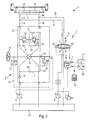
- Fig. 2 shows an embodiment of the hydraulic steering according to the invention, in which the valve block 12 and the valve unit 6 are shown in a detailed hydraulic circuit.
- reference numerals which correspond to FIG. 1 are also shown in FIG. 2 used, wherein a re-description is omitted.
- a steering valve 15 is provided, which cooperates with the handlebar 4.
- a feed port P is connected to the left connection L during a rotation weaving to the left and to the right connection R during a rotational movement by means of the steering valve 15.
- the respective other connection is connected to the tank connection T via the steering valve 15.
- spring-loaded check valve 16 is arranged between the inlet connection P and the steering valve 15 in the direction of the steering valve 15.
- a first connection channel 17 is formed, which connects the inlet connection P with the tank connection T.
- a opening in the direction of the inlet port P second check valve 18 is arranged.
- the left connection L and the right connection R are connected to one another via a second connection channel 19 and a third connection channel 20.
- a third check valve 21 and a fourth check valve 21 ' are arranged, the third check valve 21 opens in the direction of the left connection L and the fourth check valve 21' in the direction of the right connection R.
- the tank connection is further connected via a bypass line 23 to the third connection channel 20, wherein the By-pass channel 23 opens at a point of the third connecting channel 20, which opens out between the first and the second differential pressure limiting valve 22 and 22 '.
- the bypass channel 23 connects the third connection channel 20 with the second connection channel 19, wherein the connection point between the bypass channel 23 and the second connection channel 19 in turn between the third and fourth check valve 21, 21 'opens.
- the first differential pressure limiting valve 22 opens from a specific differential pressure determined by the spring of the first differential pressure limiting valve 22.
- the differential pressure limiting valve 22 is acted upon by the pressure prevailing in the left-hand line LL against the force of the spring , In the opposite direction and the same effect with the spring, the first differential pressure limiting valve 22 is acted upon by the pressure prevailing in the third connecting channel 20.
- pressure medium is removed from the left-hand line LL via the first differential pressure-limiting valve 22 in the direction of the bypass line 23.
- the discharged pressure medium continues to flow via the bypass line 23 on the one hand via the second connecting channel 19 and the subsequently open fourth check valve 21 'in the direction of the right-hand connection.
- the discharged from the left line LL pressure medium via the bypass line 23 to the tank port T is supplied and discharged into the tank 10.
- An adjustment of the pressure prevailing in the left-hand line LL and the legal line RL therefore takes place via the first differential-pressure limiting valve 22 and the fourth non-return valve 21 ', provided that the described pressure increase in the left-hand line LL does not cause the handlebar 4 to rotate and thus the steering valve 15 in one Position is located in the terminals are separated from each other.
- a line branch is provided between the throttle 24 and the control pressure port LD to avoid too large occurring control pressures, in which a third differential pressure limiting valve 25 is arranged.
- the control pressure port LD is relaxed in the direction of the tank connection T when a pressure difference exceeding a specific, adjustable value occurs.
- the valve unit 6 is designed in the figure as a 4/3-way valve. In the rest position of the valve unit 6 shown in FIG. 2, the inlet, tank, left and right ports P ', T', L 'and R' are separated from each other. Without a control by the control unit 7, the valve unit 6 is held in this rest position by two acting in the opposite direction on the valve unit 6 springs. Via the control unit 7, a first electromagnet 26 or a second electromagnet 26 'can be acted upon by a signal. The first electromagnet 26 acts on the valve unit 6 in a force in the direction of a first end position of the Valve unit 6. In this first end position of the valve unit 6, the inlet connection P 'are connected to the left connection L' of the valve unit 6, so that via the second pump 9 pressure medium is fed into the left line LL.
- the electromagnet 26' adjusts the valve unit 6 in the direction of its second end position, in which the inlet connection P 'is connected to the right connection R'.
- the valve unit 6 In the second end position of the valve unit 6 is thus sucked by the second pump 9 pressure fluid from the tank 10 and conveyed in the legal RL.
- the respectively not connected to the inlet port P 'right line R' or left line LL remains closed, so that a discharge of pressure medium via the valve unit 6 can not be done.
- the blocking device which prevents the backflow of the hydraulic medium is thus directly integrated into the valve unit 6.
- a further check valve is formed in the connection between the second pump 9 and the inlet port P 'of the valve unit 6.
- control signals sent to the first electromagnet 26 and the second electromagnet 26 ' are determined by the control unit 7 as a function of a plurality of parameters.
- the output voltage of the sensor 11 depends, for example, the angle of rotation and a speed from which correspond to the rotational movement of the link 4.
- the control signals issued by the control unit 7 can continue to be influenced by a first selector switch 27 and a second selector switch 28.
- the change of the hydraulic ratio, which is achieved by the auxiliary device 3, thus taking into account certain Operating situations are varied.
- a changed control behavior due to the movement of a work machine on the road or in the field done can thus be adapted, for example, to different speeds in the field or on the road.
- an adjustment of the parameter sets of the control unit 7 can take place via a service device 29.
- the second embodiment of the hydraulic steering according to the invention shown in FIG. 3 differs from the embodiment of FIG. 2 in that a modified valve unit 6 'is used in the auxiliary device 3.
- a modified valve unit 6 ' is used in the auxiliary device 3.
- the valve unit 6 not only the inlet connection P 'is connected to the left-hand line LL in the changed end valve position 6' in the first end position, but additionally the right-hand line RL is connected to the tank connection T '. If, however, the deflection of the changed valve unit 6 'from its rest position shown in FIG. 3 in the direction of the second end position, so on the one hand, the inlet port P' increasingly connected to the right line RL and on the other hand, the left line LL increasingly connected to the tank port T '.
- a back flow of hydraulic medium via the modified valve unit 6' is made possible. Downstream of the changed valve unit 6 ', to prevent the backflow of the hydraulic medium, a separate blocking device 30 is provided in the conduit leading to the tank 10.
- the separate blocking device 30 can also be designed to be unlockable. Depending on the particular driving situation can then both via the steering valve 15 of the valve block 12th as well as the valve unit 6 'of the auxiliary device 3 hydraulic medium are returned to the tank 10.
- unlockable locking devices are not only possible with the separate locking device 30 as shown in FIG.
- a modified version of the left check valve LR 'and the right setback RR' is used.
- the modified check valves LR 'and RR' can be acted upon by a first unlocking line 31 and a second unlocking line 32 with a hydraulic pressure, which bring the two non-return valves in their open position, regardless of the pressure conditions in the left line LL and the right line RR.
- the control of the two check valves LR 'or RR' can be carried out either jointly or independently of one another, wherein the pressure set in the first unlocking line 31 or the second unlocking line 32 can be set independently of one another.
- FIG. 5 An alternative is shown in FIG. 5.
- a non-return valve arranged between the tank connection T 'of the valve unit 6 is likewise brought into its open position via an unlocking line 33.
- the left-hand line LL or the right-hand line RL can be relaxed in the direction of the tank 10 via the tank connection T ', wherein the assignment takes place via the valve unit 6.
- a check valve 34 is also formed upstream of the inlet port P '. This check valve 34 opens in the direction of the valve unit 6 and thus secures the second pump 9 from any possible excessive pressure increase.
Landscapes
- Engineering & Computer Science (AREA)
- Chemical & Material Sciences (AREA)
- Combustion & Propulsion (AREA)
- Transportation (AREA)
- Mechanical Engineering (AREA)
- Power Steering Mechanism (AREA)
- Fluid-Pressure Circuits (AREA)
Claims (7)
- Direction hydraulique (1) avec une unité de direction hydraulique (2) qui, en fonction du mouvement d'une bielle (4), alimente un agent hydraulique à destination d'un cylindre de direction (5), et un dispositif auxiliaire (3) avec une unité de soupape (6) qui, en fonction du mouvement de la bielle (4), pour assister le mouvement de la bielle, alimente également un agent hydraulique au cylindre de direction (5),
moyennant quoi l'agent hydraulique déplacé ou s'écoulant à partir du cylindre de direction (5), par suite du l'amenée de l'agent hydraulique, peut retourner uniquement par l'unité de direction (2) dans un réservoir (10) ou vers une pompe (8, 9). - Direction hydraulique selon la revendication 1,
caractérisée en ce que
un retour de l'agent hydraulique s'écoulant à partir du cylindre de direction (5) par le dispositif auxiliaire (3) est bloqué par au moins un dispositif de blocage (LR, RR) qui ne permet l'écoulement de l'agent hydraulique que dans l'une des deux directions d'écoulement. - Direction hydraulique selon la revendication 2,
caractérisée en ce que
le dispositif de blocage (LR, RR) est une soupape anti-retour (RR, LR). - Direction hydraulique selon la revendication 2 ou 3,
caractérisée en ce que
l'unité de direction (2) présente un raccordement à gauche (L) et un raccordement à droite (R), l'unité de soupape (6) présente un raccordement à gauche (L') et un raccordement à droite (R'), les raccordements à gauche (L, L') montés en parallèle sont raccordés par l'intermédiaire d'au moins une conduite à gauche (LL) à un espace de cylindre de direction à gauche (LZ) du cylindre de direction (5) et les raccordements à droite (R, R') montés en parallèle par l'intermédiaire d'au moins une conduite à droite (RL) sont raccordés à un espace de cylindre de direction à droite (RZ), moyennant quoi le fluide hydraulique en provenance du raccordement à droite (R') et du raccordement à gauche (L') de l'unité de soupape (6) peut uniquement sortir et ne peut pas entrer. - Direction hydraulique selon la revendication 4,
caractérisée en ce que
dans la conduite à droite (RL) et la conduite à gauche (LL), en amont du raccordement à droite (R') et du raccordement à gauche (L') de l'unité de soupape (6), est disposé respectivement le au moins un dispositif de blocage (LR, RR). - Direction hydraulique selon l'une des revendications précédentes,
caractérisée en ce que
l'unité de soupape (6) est une soupape proportionnelle. - Direction hydraulique selon l'une des revendications précédentes,
caractérisée en ce que
un appareil de commande électronique (7) commande ou régule le dispositif auxiliaire (3) ou l'unité de soupape (6) en fonction d'au moins le mouvement de la bielle (4).
Applications Claiming Priority (3)
| Application Number | Priority Date | Filing Date | Title |
|---|---|---|---|
| DE102004031676 | 2004-06-30 | ||
| DE102004062387A DE102004062387A1 (de) | 2004-06-30 | 2004-12-23 | Hydraulische Lenkung mit Absicherung gegen unkontrollierte Lenkbewegungen |
| PCT/EP2005/006952 WO2006002872A1 (fr) | 2004-06-30 | 2005-06-28 | Direction hydraulique pourvue d'une protection contre les mouvements de direction incontroles |
Publications (2)
| Publication Number | Publication Date |
|---|---|
| EP1761425A1 EP1761425A1 (fr) | 2007-03-14 |
| EP1761425B1 true EP1761425B1 (fr) | 2008-02-06 |
Family
ID=34971395
Family Applications (1)
| Application Number | Title | Priority Date | Filing Date |
|---|---|---|---|
| EP05755973A Not-in-force EP1761425B1 (fr) | 2004-06-30 | 2005-06-28 | Direction hydraulique pourvue d'une protection contre les mouvements de direction incontroles |
Country Status (10)
| Country | Link |
|---|---|
| US (1) | US7694776B2 (fr) |
| EP (1) | EP1761425B1 (fr) |
| JP (1) | JP2008505017A (fr) |
| AT (1) | ATE385488T1 (fr) |
| BR (1) | BRPI0512899A (fr) |
| DE (2) | DE102004062387A1 (fr) |
| DK (1) | DK1761425T3 (fr) |
| ES (1) | ES2301022T3 (fr) |
| RU (1) | RU2007103346A (fr) |
| WO (1) | WO2006002872A1 (fr) |
Cited By (2)
| Publication number | Priority date | Publication date | Assignee | Title |
|---|---|---|---|---|
| DE102011106276A1 (de) | 2011-07-01 | 2013-01-03 | Robert Bosch Gmbh | Hydraulische Lenkung |
| EP4261645A1 (fr) * | 2022-04-12 | 2023-10-18 | Dürrstein, Ingeborg | Véhicule agricole pourvu de guidage des essieux |
Families Citing this family (7)
| Publication number | Priority date | Publication date | Assignee | Title |
|---|---|---|---|---|
| US8100220B2 (en) * | 2008-03-28 | 2012-01-24 | Rexius Forest By-Products, Inc. | Vehicle having auxiliary steering system |
| DE102008021973A1 (de) * | 2008-05-02 | 2009-11-05 | Bayerische Motoren Werke Aktiengesellschaft | Fahrzeug- Lenksystem der by-wire-Bauart |
| US8056672B2 (en) * | 2009-12-09 | 2011-11-15 | Deere & Company | Steering control system combining electro-hydraulic and manually-actuated pilot pressure control valves for safe operation |
| KR101737633B1 (ko) * | 2010-08-19 | 2017-05-18 | 두산인프라코어 주식회사 | 건설기계의 비상 조향 장치 |
| DE102013209467A1 (de) * | 2013-05-22 | 2014-11-27 | Deere & Company | Elektrohydraulisches steer-by-wire-Lenksystem |
| DE102019127735B4 (de) | 2019-10-15 | 2021-08-19 | Wirtgen Gmbh | Selbstfahrende Baumaschine |
| FR3116090B1 (fr) * | 2020-11-12 | 2023-01-06 | Manitou Bf | système de direction hydraulique pour un engin muni de roues et engin muni de roues équipé d’un tel système de direction |
Family Cites Families (10)
| Publication number | Priority date | Publication date | Assignee | Title |
|---|---|---|---|---|
| DE3515124A1 (de) | 1985-04-26 | 1986-10-30 | Xaver Fendt & Co, 8952 Marktoberdorf | Hydraulikanlage |
| DE3837395A1 (de) | 1987-11-09 | 1989-05-18 | Rexroth Mannesmann Gmbh | Hydrostatische hilfskraftlenkung fuer fahrzeuge |
| DE4031969C2 (de) | 1990-10-09 | 1994-06-09 | Danfoss As | Zweikreis-Lenksystem für Kraftfahrzeuge |
| DE19546733C1 (de) * | 1995-12-14 | 1997-03-27 | Daimler Benz Ag | Hydraulische Servolenkung |
| DE19615544C1 (de) * | 1996-04-19 | 1997-10-30 | Daimler Benz Ag | Fahrzeuglenkung |
| DE19825579B4 (de) * | 1998-06-09 | 2004-07-15 | Sauer-Danfoss Holding A/S | Hydraulische Lenkeinrichtung |
| US6209677B1 (en) * | 1998-09-09 | 2001-04-03 | Daimlerchrysler Ag | Steering system for non-tracked motor vehicles |
| DE19945125A1 (de) * | 1999-09-21 | 2001-04-12 | Sauer Danfoss Nordborg As Nord | Hydrostatische Lenkeinrichtung |
| DE10065557B4 (de) * | 2000-12-28 | 2005-03-10 | Sauer Danfoss Holding Aps Nord | Hydraulisches Lenksystem, insbesondere für ein knickgesteuertes Fahrzeug mit Radlenkung |
| DE10101827A1 (de) * | 2001-01-17 | 2002-07-18 | Daimler Chrysler Ag | Lenkanordnung für Kraftfahrzeuge |
-
2004
- 2004-12-23 DE DE102004062387A patent/DE102004062387A1/de not_active Withdrawn
-
2005
- 2005-06-28 WO PCT/EP2005/006952 patent/WO2006002872A1/fr active IP Right Grant
- 2005-06-28 JP JP2007519675A patent/JP2008505017A/ja not_active Withdrawn
- 2005-06-28 EP EP05755973A patent/EP1761425B1/fr not_active Not-in-force
- 2005-06-28 US US11/630,624 patent/US7694776B2/en not_active Expired - Fee Related
- 2005-06-28 DK DK05755973T patent/DK1761425T3/da active
- 2005-06-28 AT AT05755973T patent/ATE385488T1/de active
- 2005-06-28 ES ES05755973T patent/ES2301022T3/es active Active
- 2005-06-28 BR BRPI0512899-4A patent/BRPI0512899A/pt not_active Application Discontinuation
- 2005-06-28 RU RU2007103346/11A patent/RU2007103346A/ru unknown
- 2005-06-28 DE DE502005002764T patent/DE502005002764D1/de active Active
Cited By (2)
| Publication number | Priority date | Publication date | Assignee | Title |
|---|---|---|---|---|
| DE102011106276A1 (de) | 2011-07-01 | 2013-01-03 | Robert Bosch Gmbh | Hydraulische Lenkung |
| EP4261645A1 (fr) * | 2022-04-12 | 2023-10-18 | Dürrstein, Ingeborg | Véhicule agricole pourvu de guidage des essieux |
Also Published As
| Publication number | Publication date |
|---|---|
| WO2006002872A1 (fr) | 2006-01-12 |
| RU2007103346A (ru) | 2008-08-10 |
| DE102004062387A1 (de) | 2006-01-26 |
| ATE385488T1 (de) | 2008-02-15 |
| ES2301022T3 (es) | 2008-06-16 |
| US20080142291A1 (en) | 2008-06-19 |
| DK1761425T3 (da) | 2008-03-17 |
| DE502005002764D1 (de) | 2008-03-20 |
| JP2008505017A (ja) | 2008-02-21 |
| BRPI0512899A (pt) | 2008-04-15 |
| US7694776B2 (en) | 2010-04-13 |
| EP1761425A1 (fr) | 2007-03-14 |
Similar Documents
| Publication | Publication Date | Title |
|---|---|---|
| EP1761425B1 (fr) | Direction hydraulique pourvue d'une protection contre les mouvements de direction incontroles | |
| EP1910151B1 (fr) | Direction hydroelectrique | |
| DE2435602C3 (de) | Selbsttätige Steuereinrichtung zur Verteilung des Druckmittels auf zwei Hydrauliksysteme | |
| DE102007053024B4 (de) | Hydraulische Lenkung | |
| DE60004111T2 (de) | Kraftübertragung für ein fahrbares Gerät mit mindestens zwei angetriebenen Achsen | |
| EP1609636B1 (fr) | Dispositf de commande hydraulique | |
| DE1755297C3 (de) | Hydrostatische Hilfskraftlenkeinrichtung, insbesondere für schwere Fahrzeuge | |
| DE4319495B4 (de) | Hydraulische Servolenkvorrichtung | |
| DE2642337B2 (de) | Steuereinrichtung für einen doppeltwirkenden hydraulischen Motor | |
| DE4129508C2 (de) | Ventilanordnung zur Versorgung eines Verbrauchers aus zwei Druckmittelquellen | |
| DE2553748C3 (de) | Hydraulische Steuereinrichtung, insbesondere für Fahrzeuglenkungen | |
| DE102007033986A1 (de) | Hydraulische Lenkeinrichtung mit Stromverstärkung und hydraulischer Sicherheitsfunktion | |
| DE3802904A1 (de) | Servounterstuetzte lenkanlage | |
| DE102008028170A1 (de) | Lenksystem | |
| EP1447307B1 (fr) | Procédé pour déterminer le débit de fluide de la direction et dispositif de direction hydraulique avec amplification de débit | |
| EP4204281A1 (fr) | Dispositif de direction hydraulique | |
| DE1942086C3 (de) | Hydrostatische Hilfskraftlenkeinrichtung, insbesondere für Kraftfahrzeuge | |
| DE102016105159A1 (de) | Hydrauliksystem eines land- oder bauwirtschaftlich nutzbaren Fahrzeugs | |
| EP0839703B1 (fr) | Système de direction hydraulique à démultiplication variable et amplification de débit | |
| EP3348430B1 (fr) | Système d'amortissement hydraulique et véhicule articulé pourvu d'un tel système d'amortissement | |
| DE102004027971A1 (de) | Hydraulische Lenkeinrichtung | |
| DE60108309T2 (de) | Hydraulischer Schaltkreis einer Arbeitsmaschine | |
| EP1542878B1 (fr) | Systeme de stabilisation hydraulique pour vehicules | |
| DE2110725C2 (de) | Hydraulische Hilfskraftlenkung für Kraftfahrzeuge | |
| DE3124939C2 (de) | Hydraulische Servolenkung für Fahrzeuge |
Legal Events
| Date | Code | Title | Description |
|---|---|---|---|
| PUAI | Public reference made under article 153(3) epc to a published international application that has entered the european phase |
Free format text: ORIGINAL CODE: 0009012 |
|
| 17P | Request for examination filed |
Effective date: 20061026 |
|
| AK | Designated contracting states |
Kind code of ref document: A1 Designated state(s): AT BE BG CH CY CZ DE DK EE ES FI FR GB GR HU IE IS IT LI LT LU MC NL PL PT RO SE SI SK TR |
|
| RIN1 | Information on inventor provided before grant (corrected) |
Inventor name: RATHKE, ROLF-JOACHIM Inventor name: BERGMANN, ERHARD |
|
| 17Q | First examination report despatched |
Effective date: 20070412 |
|
| GRAP | Despatch of communication of intention to grant a patent |
Free format text: ORIGINAL CODE: EPIDOSNIGR1 |
|
| DAX | Request for extension of the european patent (deleted) | ||
| GRAS | Grant fee paid |
Free format text: ORIGINAL CODE: EPIDOSNIGR3 |
|
| GRAA | (expected) grant |
Free format text: ORIGINAL CODE: 0009210 |
|
| AK | Designated contracting states |
Kind code of ref document: B1 Designated state(s): AT BE BG CH CY CZ DE DK EE ES FI FR GB GR HU IE IS IT LI LT LU MC NL PL PT RO SE SI SK TR |
|
| REG | Reference to a national code |
Ref country code: GB Ref legal event code: FG4D Free format text: NOT ENGLISH |
|
| REG | Reference to a national code |
Ref country code: CH Ref legal event code: EP |
|
| REG | Reference to a national code |
Ref country code: DK Ref legal event code: T3 |
|
| REG | Reference to a national code |
Ref country code: SE Ref legal event code: TRGR |
|
| REG | Reference to a national code |
Ref country code: IE Ref legal event code: FG4D Free format text: LANGUAGE OF EP DOCUMENT: GERMAN |
|
| REF | Corresponds to: |
Ref document number: 502005002764 Country of ref document: DE Date of ref document: 20080320 Kind code of ref document: P |
|
| REG | Reference to a national code |
Ref country code: ES Ref legal event code: FG2A Ref document number: 2301022 Country of ref document: ES Kind code of ref document: T3 |
|
| PG25 | Lapsed in a contracting state [announced via postgrant information from national office to epo] |
Ref country code: IS Free format text: LAPSE BECAUSE OF FAILURE TO SUBMIT A TRANSLATION OF THE DESCRIPTION OR TO PAY THE FEE WITHIN THE PRESCRIBED TIME-LIMIT Effective date: 20080606 Ref country code: FI Free format text: LAPSE BECAUSE OF FAILURE TO SUBMIT A TRANSLATION OF THE DESCRIPTION OR TO PAY THE FEE WITHIN THE PRESCRIBED TIME-LIMIT Effective date: 20080206 |
|
| NLV1 | Nl: lapsed or annulled due to failure to fulfill the requirements of art. 29p and 29m of the patents act | ||
| ET | Fr: translation filed | ||
| PG25 | Lapsed in a contracting state [announced via postgrant information from national office to epo] |
Ref country code: SI Free format text: LAPSE BECAUSE OF FAILURE TO SUBMIT A TRANSLATION OF THE DESCRIPTION OR TO PAY THE FEE WITHIN THE PRESCRIBED TIME-LIMIT Effective date: 20080206 Ref country code: PL Free format text: LAPSE BECAUSE OF FAILURE TO SUBMIT A TRANSLATION OF THE DESCRIPTION OR TO PAY THE FEE WITHIN THE PRESCRIBED TIME-LIMIT Effective date: 20080206 |
|
| REG | Reference to a national code |
Ref country code: IE Ref legal event code: FD4D |
|
| PG25 | Lapsed in a contracting state [announced via postgrant information from national office to epo] |
Ref country code: CZ Free format text: LAPSE BECAUSE OF FAILURE TO SUBMIT A TRANSLATION OF THE DESCRIPTION OR TO PAY THE FEE WITHIN THE PRESCRIBED TIME-LIMIT Effective date: 20080206 Ref country code: IE Free format text: LAPSE BECAUSE OF FAILURE TO SUBMIT A TRANSLATION OF THE DESCRIPTION OR TO PAY THE FEE WITHIN THE PRESCRIBED TIME-LIMIT Effective date: 20080206 Ref country code: NL Free format text: LAPSE BECAUSE OF FAILURE TO SUBMIT A TRANSLATION OF THE DESCRIPTION OR TO PAY THE FEE WITHIN THE PRESCRIBED TIME-LIMIT Effective date: 20080206 Ref country code: PT Free format text: LAPSE BECAUSE OF FAILURE TO SUBMIT A TRANSLATION OF THE DESCRIPTION OR TO PAY THE FEE WITHIN THE PRESCRIBED TIME-LIMIT Effective date: 20080707 Ref country code: SK Free format text: LAPSE BECAUSE OF FAILURE TO SUBMIT A TRANSLATION OF THE DESCRIPTION OR TO PAY THE FEE WITHIN THE PRESCRIBED TIME-LIMIT Effective date: 20080206 |
|
| PG25 | Lapsed in a contracting state [announced via postgrant information from national office to epo] |
Ref country code: RO Free format text: LAPSE BECAUSE OF FAILURE TO SUBMIT A TRANSLATION OF THE DESCRIPTION OR TO PAY THE FEE WITHIN THE PRESCRIBED TIME-LIMIT Effective date: 20080206 |
|
| PLBE | No opposition filed within time limit |
Free format text: ORIGINAL CODE: 0009261 |
|
| STAA | Information on the status of an ep patent application or granted ep patent |
Free format text: STATUS: NO OPPOSITION FILED WITHIN TIME LIMIT |
|
| BERE | Be: lapsed |
Owner name: BRUENINGHAUS HYDROMATIK G.M.B.H. Effective date: 20080630 |
|
| 26N | No opposition filed |
Effective date: 20081107 |
|
| PG25 | Lapsed in a contracting state [announced via postgrant information from national office to epo] |
Ref country code: MC Free format text: LAPSE BECAUSE OF NON-PAYMENT OF DUE FEES Effective date: 20080630 Ref country code: LT Free format text: LAPSE BECAUSE OF FAILURE TO SUBMIT A TRANSLATION OF THE DESCRIPTION OR TO PAY THE FEE WITHIN THE PRESCRIBED TIME-LIMIT Effective date: 20080206 |
|
| PG25 | Lapsed in a contracting state [announced via postgrant information from national office to epo] |
Ref country code: BE Free format text: LAPSE BECAUSE OF NON-PAYMENT OF DUE FEES Effective date: 20080630 |
|
| PG25 | Lapsed in a contracting state [announced via postgrant information from national office to epo] |
Ref country code: EE Free format text: LAPSE BECAUSE OF FAILURE TO SUBMIT A TRANSLATION OF THE DESCRIPTION OR TO PAY THE FEE WITHIN THE PRESCRIBED TIME-LIMIT Effective date: 20080206 Ref country code: BG Free format text: LAPSE BECAUSE OF FAILURE TO SUBMIT A TRANSLATION OF THE DESCRIPTION OR TO PAY THE FEE WITHIN THE PRESCRIBED TIME-LIMIT Effective date: 20080506 |
|
| PG25 | Lapsed in a contracting state [announced via postgrant information from national office to epo] |
Ref country code: CY Free format text: LAPSE BECAUSE OF FAILURE TO SUBMIT A TRANSLATION OF THE DESCRIPTION OR TO PAY THE FEE WITHIN THE PRESCRIBED TIME-LIMIT Effective date: 20080206 |
|
| REG | Reference to a national code |
Ref country code: CH Ref legal event code: PL |
|
| PG25 | Lapsed in a contracting state [announced via postgrant information from national office to epo] |
Ref country code: CH Free format text: LAPSE BECAUSE OF NON-PAYMENT OF DUE FEES Effective date: 20090630 Ref country code: LI Free format text: LAPSE BECAUSE OF NON-PAYMENT OF DUE FEES Effective date: 20090630 |
|
| PG25 | Lapsed in a contracting state [announced via postgrant information from national office to epo] |
Ref country code: HU Free format text: LAPSE BECAUSE OF FAILURE TO SUBMIT A TRANSLATION OF THE DESCRIPTION OR TO PAY THE FEE WITHIN THE PRESCRIBED TIME-LIMIT Effective date: 20080807 Ref country code: LU Free format text: LAPSE BECAUSE OF NON-PAYMENT OF DUE FEES Effective date: 20080628 |
|
| PG25 | Lapsed in a contracting state [announced via postgrant information from national office to epo] |
Ref country code: TR Free format text: LAPSE BECAUSE OF FAILURE TO SUBMIT A TRANSLATION OF THE DESCRIPTION OR TO PAY THE FEE WITHIN THE PRESCRIBED TIME-LIMIT Effective date: 20080206 |
|
| PG25 | Lapsed in a contracting state [announced via postgrant information from national office to epo] |
Ref country code: GR Free format text: LAPSE BECAUSE OF FAILURE TO SUBMIT A TRANSLATION OF THE DESCRIPTION OR TO PAY THE FEE WITHIN THE PRESCRIBED TIME-LIMIT Effective date: 20080507 |
|
| PGFP | Annual fee paid to national office [announced via postgrant information from national office to epo] |
Ref country code: SE Payment date: 20110622 Year of fee payment: 7 Ref country code: FR Payment date: 20110630 Year of fee payment: 7 Ref country code: ES Payment date: 20110629 Year of fee payment: 7 |
|
| PGFP | Annual fee paid to national office [announced via postgrant information from national office to epo] |
Ref country code: DK Payment date: 20110623 Year of fee payment: 7 Ref country code: AT Payment date: 20110620 Year of fee payment: 7 Ref country code: GB Payment date: 20110621 Year of fee payment: 7 |
|
| PGFP | Annual fee paid to national office [announced via postgrant information from national office to epo] |
Ref country code: IT Payment date: 20110627 Year of fee payment: 7 |
|
| REG | Reference to a national code |
Ref country code: DK Ref legal event code: EBP |
|
| REG | Reference to a national code |
Ref country code: SE Ref legal event code: EUG |
|
| REG | Reference to a national code |
Ref country code: AT Ref legal event code: MM01 Ref document number: 385488 Country of ref document: AT Kind code of ref document: T Effective date: 20120628 |
|
| GBPC | Gb: european patent ceased through non-payment of renewal fee |
Effective date: 20120628 |
|
| PG25 | Lapsed in a contracting state [announced via postgrant information from national office to epo] |
Ref country code: IT Free format text: LAPSE BECAUSE OF NON-PAYMENT OF DUE FEES Effective date: 20120628 Ref country code: SE Free format text: LAPSE BECAUSE OF NON-PAYMENT OF DUE FEES Effective date: 20120629 |
|
| REG | Reference to a national code |
Ref country code: FR Ref legal event code: ST Effective date: 20130228 |
|
| PG25 | Lapsed in a contracting state [announced via postgrant information from national office to epo] |
Ref country code: GB Free format text: LAPSE BECAUSE OF NON-PAYMENT OF DUE FEES Effective date: 20120628 Ref country code: FR Free format text: LAPSE BECAUSE OF NON-PAYMENT OF DUE FEES Effective date: 20120702 |
|
| PG25 | Lapsed in a contracting state [announced via postgrant information from national office to epo] |
Ref country code: AT Free format text: LAPSE BECAUSE OF NON-PAYMENT OF DUE FEES Effective date: 20120628 |
|
| PG25 | Lapsed in a contracting state [announced via postgrant information from national office to epo] |
Ref country code: DK Free format text: LAPSE BECAUSE OF NON-PAYMENT OF DUE FEES Effective date: 20120702 |
|
| REG | Reference to a national code |
Ref country code: ES Ref legal event code: FD2A Effective date: 20131022 |
|
| PGFP | Annual fee paid to national office [announced via postgrant information from national office to epo] |
Ref country code: DE Payment date: 20130828 Year of fee payment: 9 |
|
| PG25 | Lapsed in a contracting state [announced via postgrant information from national office to epo] |
Ref country code: ES Free format text: LAPSE BECAUSE OF NON-PAYMENT OF DUE FEES Effective date: 20120629 |
|
| REG | Reference to a national code |
Ref country code: DE Ref legal event code: R119 Ref document number: 502005002764 Country of ref document: DE |
|
| REG | Reference to a national code |
Ref country code: DE Ref legal event code: R119 Ref document number: 502005002764 Country of ref document: DE Effective date: 20150101 |
|
| PG25 | Lapsed in a contracting state [announced via postgrant information from national office to epo] |
Ref country code: DE Free format text: LAPSE BECAUSE OF NON-PAYMENT OF DUE FEES Effective date: 20150101 |