EP3348430B1 - Système d'amortissement hydraulique et véhicule articulé pourvu d'un tel système d'amortissement - Google Patents
Système d'amortissement hydraulique et véhicule articulé pourvu d'un tel système d'amortissement Download PDFInfo
- Publication number
- EP3348430B1 EP3348430B1 EP17208534.2A EP17208534A EP3348430B1 EP 3348430 B1 EP3348430 B1 EP 3348430B1 EP 17208534 A EP17208534 A EP 17208534A EP 3348430 B1 EP3348430 B1 EP 3348430B1
- Authority
- EP
- European Patent Office
- Prior art keywords
- pressure
- damping system
- valve
- limiting valve
- proportional pressure
- Prior art date
- Legal status (The legal status is an assumption and is not a legal conclusion. Google has not performed a legal analysis and makes no representation as to the accuracy of the status listed.)
- Active
Links
- 238000013016 damping Methods 0.000 title claims description 83
- 230000000903 blocking effect Effects 0.000 claims description 4
- 238000011144 upstream manufacturing Methods 0.000 claims description 2
- 230000000694 effects Effects 0.000 description 4
- 230000007547 defect Effects 0.000 description 3
- 230000001419 dependent effect Effects 0.000 description 3
- 230000036316 preload Effects 0.000 description 3
- 238000009423 ventilation Methods 0.000 description 3
- 238000005452 bending Methods 0.000 description 2
- 230000007423 decrease Effects 0.000 description 2
- 230000003247 decreasing effect Effects 0.000 description 2
- 239000000243 solution Substances 0.000 description 2
- 239000006096 absorbing agent Substances 0.000 description 1
- 238000010276 construction Methods 0.000 description 1
- 230000008878 coupling Effects 0.000 description 1
- 238000010168 coupling process Methods 0.000 description 1
- 238000005859 coupling reaction Methods 0.000 description 1
- 238000010586 diagram Methods 0.000 description 1
- 239000012530 fluid Substances 0.000 description 1
- 238000012544 monitoring process Methods 0.000 description 1
- 230000008092 positive effect Effects 0.000 description 1
- 230000000630 rising effect Effects 0.000 description 1
- 230000035939 shock Effects 0.000 description 1
Images

Classifications
-
- B—PERFORMING OPERATIONS; TRANSPORTING
- B62—LAND VEHICLES FOR TRAVELLING OTHERWISE THAN ON RAILS
- B62D—MOTOR VEHICLES; TRAILERS
- B62D13/00—Steering specially adapted for trailers
-
- F—MECHANICAL ENGINEERING; LIGHTING; HEATING; WEAPONS; BLASTING
- F16—ENGINEERING ELEMENTS AND UNITS; GENERAL MEASURES FOR PRODUCING AND MAINTAINING EFFECTIVE FUNCTIONING OF MACHINES OR INSTALLATIONS; THERMAL INSULATION IN GENERAL
- F16F—SPRINGS; SHOCK-ABSORBERS; MEANS FOR DAMPING VIBRATION
- F16F9/00—Springs, vibration-dampers, shock-absorbers, or similarly-constructed movement-dampers using a fluid or the equivalent as damping medium
- F16F9/10—Springs, vibration-dampers, shock-absorbers, or similarly-constructed movement-dampers using a fluid or the equivalent as damping medium using liquid only; using a fluid of which the nature is immaterial
- F16F9/14—Devices with one or more members, e.g. pistons, vanes, moving to and fro in chambers and using throttling effect
- F16F9/16—Devices with one or more members, e.g. pistons, vanes, moving to and fro in chambers and using throttling effect involving only straight-line movement of the effective parts
- F16F9/18—Devices with one or more members, e.g. pistons, vanes, moving to and fro in chambers and using throttling effect involving only straight-line movement of the effective parts with a closed cylinder and a piston separating two or more working spaces therein
- F16F9/19—Devices with one or more members, e.g. pistons, vanes, moving to and fro in chambers and using throttling effect involving only straight-line movement of the effective parts with a closed cylinder and a piston separating two or more working spaces therein with a single cylinder and of single-tube type
-
- F—MECHANICAL ENGINEERING; LIGHTING; HEATING; WEAPONS; BLASTING
- F16—ENGINEERING ELEMENTS AND UNITS; GENERAL MEASURES FOR PRODUCING AND MAINTAINING EFFECTIVE FUNCTIONING OF MACHINES OR INSTALLATIONS; THERMAL INSULATION IN GENERAL
- F16F—SPRINGS; SHOCK-ABSORBERS; MEANS FOR DAMPING VIBRATION
- F16F9/00—Springs, vibration-dampers, shock-absorbers, or similarly-constructed movement-dampers using a fluid or the equivalent as damping medium
- F16F9/32—Details
- F16F9/44—Means on or in the damper for manual or non-automatic adjustment; such means combined with temperature correction
- F16F9/46—Means on or in the damper for manual or non-automatic adjustment; such means combined with temperature correction allowing control from a distance, i.e. location of means for control input being remote from site of valves, e.g. on damper external wall
Definitions
- the invention relates to a hydraulic damping system for damping pivotal movements of two mutually at least indirectly connected via a rotary vehicle parts with at least one designed as a double-acting hydraulic cylinder damper whose pressure and suction pressure chambers are connected to each other via a proportional pressure relief valve.
- the invention relates to an articulated vehicle in which two vehicle parts pivotally connected to each other at least indirectly via a rotary joint and guided by at least one double-acting hydraulic cylinder damping system to each other, wherein arranged in a pressure and suction pressure chambers of the at least one hydraulic cylinder connecting damping line, a proportional pressure relief valve is.
- Articulated vehicles are motor vehicles, which are preferably designed as low-floor articulated buses, these having a seen in the direction of travel, front vehicle part and a rear vehicle part. Between these, a turntable-like joint arrangement is provided, which allow for reducing the turning radius of the corresponding motor vehicle bending angle between the two vehicle parts and thereby have a substantially vertical hinge axis.
- a turntable-like joint arrangement is provided, which allow for reducing the turning radius of the corresponding motor vehicle bending angle between the two vehicle parts and thereby have a substantially vertical hinge axis.
- the coupling of the two vehicle parts and horizontally extending joint axes may be provided, around which these can execute pitching movements.
- a drive axle is provided, which is arranged as the last axis within the rear part of the vehicle and thus the entire articulated vehicle, including the front part of the vehicle on the hinge pushes.
- their mutually executed movements damping device quickly executed bending movements of the articulated vehicle could lead to its breaking.
- this Reason is arranged between the articulated parts of the joint assembly guided a damping system having at least one serving as a shock absorber double-acting hydraulic cylinder. The flow of oil between the pressure chambers of this hydraulic cylinder is throttled to achieve a damping effect.
- a rotary joint with a damping system assigned thereto is provided for the damping of the rotational movement of a rotary joint between two vehicle parts of a joint vehicle, for example a joint bus.
- the hinge has two hinge members which are pivotally connected together by a hinge axis.
- the one hinge member may in this case be articulated directly on the one vehicle part, whereas the other hinge member is pivotally connected to a horizontally extending axis, to compensate for pitching movements, directly to the other vehicle part.
- the hydraulic system is controllable, whereby an improved damping effect when cornering and driving straight ahead can be achieved.
- a parallel-connected mechanical pressure relief valve should be provided in addition to a proportional pressure relief valve.
- These two pressure relief valves are selectively controlled via a designed as a 2/2-way valve multi-way valve.
- the multi-way valve In normal operation of the damping arrangement, the multi-way valve is in its flow position, in which the proportional pressure relief valve is acted upon.
- the solenoid-operated multiway valve In case of failure of the controller or the function of the proportional pressure relief valve, ie in emergency operation, the solenoid-operated multiway valve is to be moved into a blocking position, so that the arranged in a branching off this line mechanical pressure relief valve with pressure medium from one of the pressure chambers is acted upon.
- a hydraulic damping system for damping pivotal movements of two interconnected via a rotary vehicle parts with at least one designed as a double-acting hydraulic cylinder damper.
- a double-acting having a piston provided with two piston rods, wherein the respective ends facing away from the piston of the piston rods are at least indirectly connected to the vehicle parts.
- a cooperating with a rack gear which is rotatably connected to the rotatable joint part. The rack absorbs the piston of the double-acting hydraulic cylinder.
- each piston-side pressure chamber of a hydraulic cylinder is connected to a piston rod-side pressure chamber of the other hydraulic cylinder.
- the corresponding pressure and suction pressure chambers are connected to each other in both designs and arrangements of the hydraulic cylinder or via a proportional pressure relief valve. This provides in the pressure chamber, is displaced from the pressure medium, for a pressure build-up and a pressure-dependent opening for a damped pressure drop in the corresponding damper line, so that the movement of the piston or is damped.
- the proportional pressure relief valve is designed as an electrically pilot-controlled inverse proportional pressure relief valve with which a nominal pressure is adjustable in the de-energized state of a proportional solenoid or in case of failure of the electromagnetic actuation in the damping system.
- This inverse proportional pressure relief valve thus has a function after which when rising electrical input signal, the pressure drops as it rises with decreasing input signal.
- the set pressure to increase to the nominal pressure, which ensures safe emergency operation of the articulated vehicle. For a sufficient damping behavior of the damping system is obtained in such defects, so that the articulated vehicle can continue its journey to a workshop.
- the damping system according to the EP 1 010 608 B1 a designed as a 2/2-way valve or 3/2-way valve multi-way valve, which connects in normal operation, the respective pressure chamber whose volume decreases exclusively with an electromagnetically actuated proportional pressure relief valve.
- the inflow to the electromagnetically actuated proportional pressure limiting valve is blocked and made an exclusive connection of the respective pressure chamber with a parallel or in series with the aforementioned proportional pressure relief valve mechanically operated pressure relief valve.
- the latter is set to a certain minimum pressure, which should be effective in emergency mode.
- This control of the damping system requires a total of three valves, which increases the construction cost.
- in case of failure of the control of the damping system despite emergency damping characteristics of the hydraulic system to unstable driving conditions of the vehicle, such as a rocking come.
- a proportional pressure relief valve is connected in series, and that in an emergency operation of the damping system, a hydraulic pressure in the respective pressure chamber can be achieved only via the inverse proportional pressure relief valve.
- the emergency damping pressure must be able to be lowered to a pressure level in case of failure of the electric control to ensure the steerability of the articulated vehicle. In this operation of the vehicle, a reduced damping of the movements of the swivel joint is to be made possible.
- a proportional pressure relief valve which is preferably actuated electromagnetically, are connected in series with the inverse proportional pressure relief valve.
- Both Proportional pressure relief valves work logically in an "AND" combination, so that the respective set pressures add up. This ensures that both in case of failure of the on-board voltage as well as specified specification electrical control of the required hydraulic pressure is guaranteed.
- the electrically controlled proportional pressure relief valve is preferably pre-controlled as a function of driving speed.
- the inverse proportional pressure relief valve is also energized in normal driving, in such a way that it assumes an inverse control function based on the proportional pressure relief valve.
- the normal proportional pressure relief valve is set to a high pressure and the inverse proportional pressure relief valve is set to a low pressure.
- the reverse pressure conditions are present.
- the normal proportional pressure relief valve enters a position in which only a very low or no pressure is built up, while the likewise de-energized inverse proportional pressure relief valve adjusts an emergency damping pressure.
- the inverse proportional pressure relief valve may be connected upstream of the proportional pressure relief valve.
- the inverse proportional pressure relief valve has a pilot stage, which is adjusted at a reduction or a failure of the control current in a blocking or throttle position and builds up a control pressure to a main piston of the inverse proportional pressure relief valve.
- a pressure relief valve may be connected in parallel to limit the pressure in the pressure chambers and acting on piston rods of the at least one hydraulic cylinder forces to the inverse proportional pressure relief valve, a pressure relief valve. It should be set to serve as a safety valve pressure relief valve to a maximum allowable pressure of the damping system, which is specified by the buckling safety of the piston rods.
- the electromagnetically controlled proportional pressure relief valve can have a range of the respective limiting pressure of 0-350 bar, whereby a maximum damping pressure of less than 200 bar results by adding these pressures to the pressures built up by the inverse proportional pressure limiting valve.
- the parallel-connected pressure relief valve is set to an opening pressure of 200 bar.
- a damping line accommodating the inverse proportional pressure relief valve and the proportional pressure limiting valve can be connected from this tank line connected to a tank to a biasing valve.
- the biasing valve establishes a bias pressure in the conduit sections, which are respectively connected to the increasing pressure chamber, which results in that the pressure chamber is forcibly filled. This prevents cavitation, which could occur during rapid movements of the piston arranged in the hydraulic cylinder.
- a sucking in of pressure fluid into at least one of the pressure chambers can be achieved by connecting at least one of the pressure chambers via at least one unlockable check valve to an oil reservoir of a tank.
- the at least one unlockable check valve can be actuated via a connected to one of the pressure chambers control line in its open position.
- the control line can emanate from the hollow cylindrical control chamber. The pressure generated by the proportional pressure relief valve is supplied to the pilot-operated check valve, for example, via the hollow cylindrical control chamber and the control line, so that this establishes a connection between the reservoir tank and the cylindrical pressure chamber and an oil flow into the pressure chamber.
- the object is in a hydraulic damping system for damping pivotal movements of two at least indirectly interconnected vehicle parts via a rotary joint with at least one designed as a double-acting hydraulic cylinder damper whose pressure and suction pressure chambers via a proportional pressure relief valve connected to each other, also solved in that at least one of the pressure chambers is connected via at least one pilot-operated check valve with an oil reservoir of a tank.
- a corresponding possibility for a Nachsaugen of pressure medium from an oil reservoir should therefore also be provided if in the damper line only an electromagnetically pilot operated proportional pressure relief valve is arranged.
- Also in this case may be connected to the tank connected to the tank a return valve receiving return line on the outlet side of the proportional pressure relief valve. Also by means of this preload valve cavitation is prevented in the damping system.
- a proportional pressure relief valve in an articulated vehicle in which two vehicle parts are pivotally connected to each other at least indirectly via a rotary joint and guided to each other by means of at least one double-acting hydraulic cylinder of a damping system to be arranged in a pressure and suction pressure chambers of the at least one hydraulic cylinder connecting the damping line, a proportional pressure relief valve.
- the damping system according to one of the claims 1 to 11 should be formed.
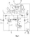
- FIGS. 1 . 2, 4 and 5 1 denotes a double-acting hydraulic cylinder which has a piston 3 provided with a piston rod 2.
- the piston 3 is longitudinally displaceably guided in a cylinder 4 and limited in this a cylindrical pressure chamber 5 and a hollow cylindrical pressure chamber 6. From the pressure chambers 5 and 6 lead pressure lines 7 and 8 to a damping circuit 9, in the targeted guidance and blocking of the pressure medium flow check valves 10, 11, 12 and 13 are arranged.
- the damping circuit 9 is bridged by a damper line 14, which receives an inverse proportional pressure relief valve 15 and a proportional pressure relief valve 16 connected downstream of this.
- Both proportional pressure relief valves 15 and 16 are pre-controlled via an electrical control current, wherein the corresponding control and control lines are not shown in detail.
- the proportional pressure relief valve 16 provides for a pressure change in the respective pressure line 7 or 8, from which it is flown, wherein this pressurization proportional to the electric current with which it is controlled, is changed. This electric current is preferably changed depending on the driving speed of a joint vehicle.
- the inverse proportional pressure relief valve 15 is also energized while driving and thus influenced together with the downstream of this proportional pressure relief valve 16, the pressure in the pressure lines 7 and 8. These pressure changes by means of the two proportional pressure relief valves 15 and 16 will be discussed in more detail below ,
- the check valves 11 and 12 are the pressure lines 7 and 8 in such a way with the damping circuit 9 that a pressure medium displaced from these pressure chambers 5 or 6 passes into the damper line 14.
- the check valves 10 and 13 block a flow of the pressure medium in the damping circuit 9 in a direction away from the damper line 14 direction.
- Each of one of the pressure chambers 5 or 6 displaced pressure medium is thus selectively fed to the damper line 14.
- a connecting line 17 which receives a serving as a safety valve pressure relief valve 18.
- a tank line 19 in which a biasing valve 20, which is also designed as a pressure relief valve, is arranged. This tank line 19 opens into an oil reservoir 21.
- the cylindrical pressure chamber 5 communicates via a suction line 22 with the oil reservoir 21, wherein a check valve unit 23 is located within the suction line 22.
- This check valve unit 23 consists of two pilot-operated check valves 24 and 25, which are actuated via a connected to the hollow cylindrical pressure chamber 6 control line 26 in its open position.
- a designated 27 pressure sensor is connected to the damping circuit 9 for monitoring the damping system.
- the function of the damping system is the following: During a straight ahead or cornering one with a joint arrangement, for example according to FIG. 6 , Provided articulated vehicle act pressure forces on the piston rod 2 and thus on the piston 3, so that in a corresponding manner, the pressure of the pressure chambers located in the pressure chambers 5 and 6 increases. If this pressure increase occurs, for example, in the pressure chamber 5, it is transmitted via the respective non-return valve 11 or 12 into the damping circuit 9 and is thus on the damper line 14 initially on the inverse proportional pressure relief valve 15 and performs depending on the height of the pressure to the Activity.
- the emerging from the inverse proportional pressure relief valve 15 pressure medium passes in a second stage to the downstream of this proportional pressure relief valve 16, which may be adjustable for example to a limiting pressure of 0 - 350 bar.
- proportional pressure relief valve is generally understood to mean pressure valves which continuously convert a variable input signal into a hydraulic output signal.
- the effluent from the damper line 14 pressure medium is thus finally passed through the proportional pressure relief valve 16 under pressure drop in the other line section of the damping circuit, where it passes through the check valve 10 in the hollow cylindrical pressure chamber 6.
- the check valve 11 blocks this line section from the pressurized line section of the damping circuit 9.
- a portion of the pressure medium can flow via the biasing valve 20 into the oil reservoir 21, which is required inter alia, since the volumes of the pressure chambers 5 and 6 differ from each other due to different cross-sectional areas.
- the pressure generated by the proportional pressure relief valve 16 in the pressure chamber 6 is transmitted via the control line 26 to the pilot-operated check valve unit 23. This establishes a connection between the oil reservoir 21 and the pressure chamber 5, so that a missing oil volume can be compensated. So that this amount of oil can be sucked from the oil reservoir 21, this is provided with a ventilation filter 28 having a ventilation via which a corresponding amount of air flows into the oil reservoir 21 or exits again from this.
- the inverse proportional pressure relief valve 15 is designed such that it is provided in the currentless state of one in the pilot control unit Proportional magnets or in case of failure of the electromagnetic actuation in the damping system can set a nominal pressure. It has a function according to which, with an increasing electrical input signal, the pressure generated in the respective pressure line 7 or 8 decreases, whereas this increases with a sinking single-gear signal. Thus, the effect of the inverse proportional pressure relief valve 15 of this in the damper line 14 subsequent proportional pressure relief valve 16 is opposite.
- these two proportional pressure-limiting valves 15 and 16 are matched with respect to their pressure profiles so that a specific damping pressure can be set via this unit as a function of the respective driving conditions of the articulated vehicle.
- the proportional pressure relief valve 16 have a controllable limiting pressure of 0-350 bar.
- the inverse proportional pressure relief valve 15 will have a lowest value of the limiting pressure, which is predetermined in order to drive the articulated vehicle safely to the next workshop during emergency operation of the damping system.
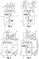
- the double-acting hydraulic cylinder 1 in an embodiment in which this has a further piston rod 2 '.
- the damping system consists only of the damping circuit 9 and the damper line 14 with the inverse proportional pressure relief valve 15 and the proportional pressure relief valve 16. In this case, so was both on a Connection line with a further pressure relief valve as well as on an oil reservoir with a tank line, a biasing valve and a device for sucking the pressure medium dispensed.
- the double-acting hydraulic cylinder 1 has two pressure chambers 6 and 6 ', which are both formed as a hollow cylinder.
- FIGS. 4 and 5 is in accordance with the FIG. 1 the pressure chamber 5 associated with a Nachsaug Rhein containing the already explained oil reservoir, the check valve unit 23 and the control line 26.
- the tank line with the biasing valve 20 disposed therein starts from the damper circuit 9, the tank line with the biasing valve 20 disposed therein.
- the electrically piloted proportional pressure relief valve 16 is arranged in the damper line 14.
- Both the inverse proportional pressure relief valve 15 and the electrically piloted proportional pressure relief valve 16 are arranged in the damper line 14. In both cases, was dispensed with the connecting line with the pressure relief valve.
- FIG. 6 shows a hinge assembly 29 for a non-illustrated articulated vehicle, which should preferably be designed as an articulated bus.
- This consists of a front vehicle part 30 and a rear vehicle part 31, which are connected to each other via a rotary joint 32.
- the articulated vehicle is driven by a non-illustrated drive axle, which is located in the rear part of the vehicle.
- the vehicle parts 30 and 31 are guided over the double-acting hydraulic cylinders 1 and 1 'of the above-described damping system to each other such that they are stabilized during a straight-ahead or cornering, so can not break out.
- a possible embodiment of the inverse proportional pressure relief valve 15 is a schematic representation of the FIG. 7 out. Thereafter, the proportional pressure relief valve 15, a housing 33, in which a main valve 34 and a pilot stage 35 are arranged.
- the pilot stage 35 has an armature 36 and coils 37, wherein the armature 36 with a seat valve body 38 which cooperates with a provided in the housing 33 valve seat 39.
- the main valve 34 consists of a displaceably guided in the housing 33 and supported by a valve spring 40 in this control piston 41.
- the control piston 41 is connected via a first port 42 of the housing 33 with the pressure from one of the pressure chambers (see FIG.
Landscapes
- Engineering & Computer Science (AREA)
- General Engineering & Computer Science (AREA)
- Mechanical Engineering (AREA)
- Chemical & Material Sciences (AREA)
- Combustion & Propulsion (AREA)
- Transportation (AREA)
- Vehicle Body Suspensions (AREA)
Claims (12)
- Système d'amortissement hydraulique pour l'amortissement de mouvements pivotants de deux parties de véhicule (30 et 31) reliées entre elles au moins indirectement par l'intermédiaire d'une articulation pivotante (32), comprenant au moins un amortisseur qui est conformé en vérin hydraulique à double effet (1, 1') et dont les chambres de pression côté refoulement et côté aspiration (5, 5', 6, 6') sont reliées entre elles par l'intermédiaire d'une valve de limitation de pression proportionnelle, caractérisé en ce que la valve de limitation de pression proportionnelle est conformée en valve de limitation de pression proportionnelle inverse pilotée électriquement (15), avec laquelle une pression nominale peut être établie dans le système d'amortissement à l'état sans courant d'un aimant proportionnel (36) ou en cas de défaillance de l'actionnement électromagnétique.
- Système d'amortissement hydraulique selon la revendication 1, caractérisé en ce qu'une valve de limitation de pression proportionnelle (16) est montée en série avec la valve de limitation de pression proportionnelle inverse (15), et en ce que, dans un fonctionnement d'urgence du système d'amortissement, une pression hydraulique est atteignable dans la chambre de pression respective (5, 5', 6, 6') uniquement par l'intermédiaire de la valve de limitation de pression proportionnelle inverse (15).
- Système d'amortissement hydraulique selon la revendication 2, caractérisé en ce que la valve de limitation de pression proportionnelle inverse (15) est disposée en amont de la valve de limitation de pression proportionnelle (16).
- Système d'amortissement hydraulique selon la revendication 1, caractérisé en ce que, en cas de diminution du flux pilote, un étage pilote (35) de la valve de limitation de pression proportionnelle inverse (15) est déplacé dans une position d'arrêt et établit une pression de commande au niveau d'un piston principal (41) de la valve de limitation de pression proportionnelle inverse (15).
- Système d'amortissement hydraulique selon la revendication 1, caractérisé en ce que, pour limiter la pression dans les chambres de pression (5, 5', 6, 6') et les forces agissant sur les tiges de pistons (2, 2') du au moins un vérin hydraulique (1, 1'), une valve de limitation de pression (18) est montée en parallèle à la valve de limitation de pression proportionnelle inverse (15).
- Système d'amortissement hydraulique selon la revendication 1, caractérisé en ce qu'au côté sortie d'une conduite d'amortisseur (14) recevant la valve de limitation de pression proportionnelle inverse (15) et la valve de limitation de pression proportionnelle (16) est reliée, à partir de ladite conduite, une conduite de réservoir (19) reliée à un réservoir d'huile (21) et recevant une valve de précontrainte (20).
- Système d'amortissement hydraulique selon la revendication 1, caractérisé en ce qu'au moins une des chambres de pression (5) peut être reliée à un réservoir d'huile (21) par l'intermédiaire d'au moins une valve anti-retour déblocable (24, 25).
- Système d'amortissement hydraulique selon la revendication 7, caractérisé en ce que la au moins une valve anti-retour déblocable (24, 25) peut être amenée dans sa position ouverte par l'intermédiaire d'une conduite pilote (26) reliée à une des chambres de pression (6).
- Système d'amortissement hydraulique pour l'amortissement de mouvements pivotants de deux parties de véhicule (30 et 31) reliées entre elles au moins indirectement par l'intermédiaire d'une articulation pivotante (32), comprenant au moins un amortisseur qui est conformé en vérin hydraulique à double effet (1) et dont les chambres de pression côté refoulement et côté aspiration (5, 6) sont reliées entre elles par l'intermédiaire d'une valve de limitation de pression proportionnelle, caractérisé en ce qu'au moins une des chambres de pression (5) peut être reliée à un réservoir d'huile (21) par l'intermédiaire d'au moins une valve anti-retour déblocable (24, 25).
- Système d'amortissement hydraulique selon la revendication 9, caractérisé en ce que la au moins une valve anti-retour déblocable (24, 25) peut être amenée dans sa position ouverte par l'intermédiaire d'une conduite pilote (26) reliée à une des chambres de pression (6).
- Système d'amortissement hydraulique selon la revendication 9, caractérisé en ce que le système d'amortissement est conformé selon une des revendications 1 à 6.
- Véhicule articulé dans lequel deux parties de véhicule (30 et 31) sont reliées entre elles de manière pivotante au moins indirectement par l'intermédiaire d'une articulation pivotante (32) et sont guidées l'une par rapport à l'autre au moyen d'au moins un vérin hydraulique à double effet (1, 1') d'un système d'amortissement, une valve de limitation de pression proportionnelle étant disposée sur une conduite d'amortisseur (14) reliant des chambres de pression côté refoulement et côté aspiration (5, 5', 6, 6') du au moins un vérin hydraulique (1, 1'), caractérisé selon une des revendications 1 à 11.
Applications Claiming Priority (1)
| Application Number | Priority Date | Filing Date | Title |
|---|---|---|---|
| DE102017100395.9A DE102017100395A1 (de) | 2017-01-11 | 2017-01-11 | Hydraulisches Dämpfungssystem und Gelenkfahrzeug mit einem derartigen Dämpfungssystem |
Publications (2)
| Publication Number | Publication Date |
|---|---|
| EP3348430A1 EP3348430A1 (fr) | 2018-07-18 |
| EP3348430B1 true EP3348430B1 (fr) | 2019-07-24 |
Family
ID=60674018
Family Applications (1)
| Application Number | Title | Priority Date | Filing Date |
|---|---|---|---|
| EP17208534.2A Active EP3348430B1 (fr) | 2017-01-11 | 2017-12-19 | Système d'amortissement hydraulique et véhicule articulé pourvu d'un tel système d'amortissement |
Country Status (3)
| Country | Link |
|---|---|
| EP (1) | EP3348430B1 (fr) |
| CA (1) | CA2991600C (fr) |
| DE (1) | DE102017100395A1 (fr) |
Cited By (1)
| Publication number | Priority date | Publication date | Assignee | Title |
|---|---|---|---|---|
| CN110966344A (zh) * | 2019-12-27 | 2020-04-07 | 博迈科海洋工程股份有限公司 | 一种hvac机械间自调节液压隔振系统 |
Family Cites Families (3)
| Publication number | Priority date | Publication date | Assignee | Title |
|---|---|---|---|---|
| DE19716331A1 (de) * | 1997-04-18 | 1998-10-22 | Claas Saulgau Gmbh | Hydraulische Steueranordnung für wenigstens einen doppeltwirkenden Hubzylinder |
| DE29822472U1 (de) | 1998-12-18 | 1999-04-01 | Huebner Gummi & Kunststoff | Hydraulikanlage für die Dämpfung der Drehbewegung eines Drehgelenkes zwischen zwei Fahrzeugteilen eines Gelenkfahrzeuges, z.B. eines Gelenkbusses |
| DE20317243U1 (de) * | 2003-11-06 | 2005-03-17 | Hemscheidt Fahrwerktech Gmbh | Dämpfungsventilanordnung für hydraulische Schwingungsdämpfer |
-
2017
- 2017-01-11 DE DE102017100395.9A patent/DE102017100395A1/de not_active Withdrawn
- 2017-12-19 EP EP17208534.2A patent/EP3348430B1/fr active Active
-
2018
- 2018-01-10 CA CA2991600A patent/CA2991600C/fr active Active
Non-Patent Citations (1)
| Title |
|---|
| None * |
Cited By (2)
| Publication number | Priority date | Publication date | Assignee | Title |
|---|---|---|---|---|
| CN110966344A (zh) * | 2019-12-27 | 2020-04-07 | 博迈科海洋工程股份有限公司 | 一种hvac机械间自调节液压隔振系统 |
| CN110966344B (zh) * | 2019-12-27 | 2021-07-20 | 博迈科海洋工程股份有限公司 | 一种hvac机械间自调节液压隔振系统 |
Also Published As
| Publication number | Publication date |
|---|---|
| CA2991600C (fr) | 2020-03-24 |
| DE102017100395A1 (de) | 2018-07-12 |
| EP3348430A1 (fr) | 2018-07-18 |
| CA2991600A1 (fr) | 2018-07-11 |
Similar Documents
| Publication | Publication Date | Title |
|---|---|---|
| DE102014018788B3 (de) | Kraftfahrzeug-Fahrgestell | |
| EP0850151B1 (fr) | Dispositif antiroulis d'un vehicule | |
| DE102006002983B4 (de) | Aktives Fahrwerksystem eines Fahrzeugs | |
| EP1609636B1 (fr) | Dispositf de commande hydraulique | |
| DE102005035171A1 (de) | Elektrohydraulische Lenkung | |
| DE102005006321A1 (de) | Ventil, insbesondere Proportinal-Druckbegrenzungsventil | |
| WO2001064464A1 (fr) | Systeme de stabilisation hydraulique | |
| EP1761425B1 (fr) | Direction hydraulique pourvue d'une protection contre les mouvements de direction incontroles | |
| EP2463179B1 (fr) | Agencement des soupapes pour commander un système de guidage supplémentaire dans des véhicules à plusieurs axes, en particulier des grues mobiles | |
| DE19646500C2 (de) | Einrichtung zur Rollstabilisierung eines Fahrzeugs | |
| EP3348430B1 (fr) | Système d'amortissement hydraulique et véhicule articulé pourvu d'un tel système d'amortissement | |
| DE102008028170A1 (de) | Lenksystem | |
| DE102006002959A1 (de) | Hydrauliksystem mit volumenstromgeregelter Pumpe | |
| DE102004027971B4 (de) | Hydraulische Lenkeinrichtung | |
| DE102014211582A1 (de) | Elektronisch schlupfregelbare Fahrzeugbremsanlage | |
| DE112004000076B4 (de) | Anti-Wank-System | |
| DE19629582A1 (de) | Einrichtung zur Rollstabilisierung eines Fahrzeugs | |
| EP1542878B1 (fr) | Systeme de stabilisation hydraulique pour vehicules | |
| DE102004051601A1 (de) | Wankstabilisierungssystem für ein zweispuriges Fahrzeug | |
| DE102016105159A1 (de) | Hydrauliksystem eines land- oder bauwirtschaftlich nutzbaren Fahrzeugs | |
| DE102015120131B4 (de) | Lenksystem zum Betreiben eines Lenksystems | |
| DE102004040940A1 (de) | Baugruppe für ein Fahrwerkstabilisierungssystem | |
| EP2216235B1 (fr) | Découplage d'une direction auxiliaire hydraulique | |
| EP2016317A1 (fr) | Dispositif borne de raccordement avec soupape de pression | |
| DE19949152A1 (de) | Hydropneumatische Federung |
Legal Events
| Date | Code | Title | Description |
|---|---|---|---|
| PUAI | Public reference made under article 153(3) epc to a published international application that has entered the european phase |
Free format text: ORIGINAL CODE: 0009012 |
|
| STAA | Information on the status of an ep patent application or granted ep patent |
Free format text: STATUS: THE APPLICATION HAS BEEN PUBLISHED |
|
| AK | Designated contracting states |
Kind code of ref document: A1 Designated state(s): AL AT BE BG CH CY CZ DE DK EE ES FI FR GB GR HR HU IE IS IT LI LT LU LV MC MK MT NL NO PL PT RO RS SE SI SK SM TR |
|
| AX | Request for extension of the european patent |
Extension state: BA ME |
|
| STAA | Information on the status of an ep patent application or granted ep patent |
Free format text: STATUS: REQUEST FOR EXAMINATION WAS MADE |
|
| 17P | Request for examination filed |
Effective date: 20190118 |
|
| RBV | Designated contracting states (corrected) |
Designated state(s): AL AT BE BG CH CY CZ DE DK EE ES FI FR GB GR HR HU IE IS IT LI LT LU LV MC MK MT NL NO PL PT RO RS SE SI SK SM TR |
|
| GRAP | Despatch of communication of intention to grant a patent |
Free format text: ORIGINAL CODE: EPIDOSNIGR1 |
|
| STAA | Information on the status of an ep patent application or granted ep patent |
Free format text: STATUS: GRANT OF PATENT IS INTENDED |
|
| INTG | Intention to grant announced |
Effective date: 20190423 |
|
| GRAS | Grant fee paid |
Free format text: ORIGINAL CODE: EPIDOSNIGR3 |
|
| GRAA | (expected) grant |
Free format text: ORIGINAL CODE: 0009210 |
|
| STAA | Information on the status of an ep patent application or granted ep patent |
Free format text: STATUS: THE PATENT HAS BEEN GRANTED |
|
| AK | Designated contracting states |
Kind code of ref document: B1 Designated state(s): AL AT BE BG CH CY CZ DE DK EE ES FI FR GB GR HR HU IE IS IT LI LT LU LV MC MK MT NL NO PL PT RO RS SE SI SK SM TR |
|
| REG | Reference to a national code |
Ref country code: GB Ref legal event code: FG4D Free format text: NOT ENGLISH |
|
| REG | Reference to a national code |
Ref country code: CH Ref legal event code: EP |
|
| REG | Reference to a national code |
Ref country code: DE Ref legal event code: R096 Ref document number: 502017001847 Country of ref document: DE |
|
| REG | Reference to a national code |
Ref country code: AT Ref legal event code: REF Ref document number: 1157742 Country of ref document: AT Kind code of ref document: T Effective date: 20190815 |
|
| REG | Reference to a national code |
Ref country code: IE Ref legal event code: FG4D Free format text: LANGUAGE OF EP DOCUMENT: GERMAN |
|
| REG | Reference to a national code |
Ref country code: NL Ref legal event code: MP Effective date: 20190724 |
|
| REG | Reference to a national code |
Ref country code: LT Ref legal event code: MG4D |
|
| PG25 | Lapsed in a contracting state [announced via postgrant information from national office to epo] |
Ref country code: HR Free format text: LAPSE BECAUSE OF FAILURE TO SUBMIT A TRANSLATION OF THE DESCRIPTION OR TO PAY THE FEE WITHIN THE PRESCRIBED TIME-LIMIT Effective date: 20190724 Ref country code: NO Free format text: LAPSE BECAUSE OF FAILURE TO SUBMIT A TRANSLATION OF THE DESCRIPTION OR TO PAY THE FEE WITHIN THE PRESCRIBED TIME-LIMIT Effective date: 20191024 Ref country code: LT Free format text: LAPSE BECAUSE OF FAILURE TO SUBMIT A TRANSLATION OF THE DESCRIPTION OR TO PAY THE FEE WITHIN THE PRESCRIBED TIME-LIMIT Effective date: 20190724 Ref country code: PT Free format text: LAPSE BECAUSE OF FAILURE TO SUBMIT A TRANSLATION OF THE DESCRIPTION OR TO PAY THE FEE WITHIN THE PRESCRIBED TIME-LIMIT Effective date: 20191125 Ref country code: NL Free format text: LAPSE BECAUSE OF FAILURE TO SUBMIT A TRANSLATION OF THE DESCRIPTION OR TO PAY THE FEE WITHIN THE PRESCRIBED TIME-LIMIT Effective date: 20190724 Ref country code: BG Free format text: LAPSE BECAUSE OF FAILURE TO SUBMIT A TRANSLATION OF THE DESCRIPTION OR TO PAY THE FEE WITHIN THE PRESCRIBED TIME-LIMIT Effective date: 20191024 Ref country code: FI Free format text: LAPSE BECAUSE OF FAILURE TO SUBMIT A TRANSLATION OF THE DESCRIPTION OR TO PAY THE FEE WITHIN THE PRESCRIBED TIME-LIMIT Effective date: 20190724 Ref country code: SE Free format text: LAPSE BECAUSE OF FAILURE TO SUBMIT A TRANSLATION OF THE DESCRIPTION OR TO PAY THE FEE WITHIN THE PRESCRIBED TIME-LIMIT Effective date: 20190724 |
|
| PG25 | Lapsed in a contracting state [announced via postgrant information from national office to epo] |
Ref country code: GR Free format text: LAPSE BECAUSE OF FAILURE TO SUBMIT A TRANSLATION OF THE DESCRIPTION OR TO PAY THE FEE WITHIN THE PRESCRIBED TIME-LIMIT Effective date: 20191025 Ref country code: LV Free format text: LAPSE BECAUSE OF FAILURE TO SUBMIT A TRANSLATION OF THE DESCRIPTION OR TO PAY THE FEE WITHIN THE PRESCRIBED TIME-LIMIT Effective date: 20190724 Ref country code: AL Free format text: LAPSE BECAUSE OF FAILURE TO SUBMIT A TRANSLATION OF THE DESCRIPTION OR TO PAY THE FEE WITHIN THE PRESCRIBED TIME-LIMIT Effective date: 20190724 Ref country code: ES Free format text: LAPSE BECAUSE OF FAILURE TO SUBMIT A TRANSLATION OF THE DESCRIPTION OR TO PAY THE FEE WITHIN THE PRESCRIBED TIME-LIMIT Effective date: 20190724 Ref country code: RS Free format text: LAPSE BECAUSE OF FAILURE TO SUBMIT A TRANSLATION OF THE DESCRIPTION OR TO PAY THE FEE WITHIN THE PRESCRIBED TIME-LIMIT Effective date: 20190724 Ref country code: IS Free format text: LAPSE BECAUSE OF FAILURE TO SUBMIT A TRANSLATION OF THE DESCRIPTION OR TO PAY THE FEE WITHIN THE PRESCRIBED TIME-LIMIT Effective date: 20191124 |
|
| PG25 | Lapsed in a contracting state [announced via postgrant information from national office to epo] |
Ref country code: TR Free format text: LAPSE BECAUSE OF FAILURE TO SUBMIT A TRANSLATION OF THE DESCRIPTION OR TO PAY THE FEE WITHIN THE PRESCRIBED TIME-LIMIT Effective date: 20190724 |
|
| PG25 | Lapsed in a contracting state [announced via postgrant information from national office to epo] |
Ref country code: DK Free format text: LAPSE BECAUSE OF FAILURE TO SUBMIT A TRANSLATION OF THE DESCRIPTION OR TO PAY THE FEE WITHIN THE PRESCRIBED TIME-LIMIT Effective date: 20190724 Ref country code: IT Free format text: LAPSE BECAUSE OF FAILURE TO SUBMIT A TRANSLATION OF THE DESCRIPTION OR TO PAY THE FEE WITHIN THE PRESCRIBED TIME-LIMIT Effective date: 20190724 Ref country code: EE Free format text: LAPSE BECAUSE OF FAILURE TO SUBMIT A TRANSLATION OF THE DESCRIPTION OR TO PAY THE FEE WITHIN THE PRESCRIBED TIME-LIMIT Effective date: 20190724 Ref country code: RO Free format text: LAPSE BECAUSE OF FAILURE TO SUBMIT A TRANSLATION OF THE DESCRIPTION OR TO PAY THE FEE WITHIN THE PRESCRIBED TIME-LIMIT Effective date: 20190724 Ref country code: PL Free format text: LAPSE BECAUSE OF FAILURE TO SUBMIT A TRANSLATION OF THE DESCRIPTION OR TO PAY THE FEE WITHIN THE PRESCRIBED TIME-LIMIT Effective date: 20190724 |
|
| PG25 | Lapsed in a contracting state [announced via postgrant information from national office to epo] |
Ref country code: IS Free format text: LAPSE BECAUSE OF FAILURE TO SUBMIT A TRANSLATION OF THE DESCRIPTION OR TO PAY THE FEE WITHIN THE PRESCRIBED TIME-LIMIT Effective date: 20200224 Ref country code: SK Free format text: LAPSE BECAUSE OF FAILURE TO SUBMIT A TRANSLATION OF THE DESCRIPTION OR TO PAY THE FEE WITHIN THE PRESCRIBED TIME-LIMIT Effective date: 20190724 Ref country code: CZ Free format text: LAPSE BECAUSE OF FAILURE TO SUBMIT A TRANSLATION OF THE DESCRIPTION OR TO PAY THE FEE WITHIN THE PRESCRIBED TIME-LIMIT Effective date: 20190724 Ref country code: SM Free format text: LAPSE BECAUSE OF FAILURE TO SUBMIT A TRANSLATION OF THE DESCRIPTION OR TO PAY THE FEE WITHIN THE PRESCRIBED TIME-LIMIT Effective date: 20190724 |
|
| REG | Reference to a national code |
Ref country code: DE Ref legal event code: R097 Ref document number: 502017001847 Country of ref document: DE |
|
| PLBE | No opposition filed within time limit |
Free format text: ORIGINAL CODE: 0009261 |
|
| STAA | Information on the status of an ep patent application or granted ep patent |
Free format text: STATUS: NO OPPOSITION FILED WITHIN TIME LIMIT |
|
| PG2D | Information on lapse in contracting state deleted |
Ref country code: IS |
|
| 26N | No opposition filed |
Effective date: 20200603 |
|
| REG | Reference to a national code |
Ref country code: BE Ref legal event code: MM Effective date: 20191231 |
|
| PG25 | Lapsed in a contracting state [announced via postgrant information from national office to epo] |
Ref country code: SI Free format text: LAPSE BECAUSE OF FAILURE TO SUBMIT A TRANSLATION OF THE DESCRIPTION OR TO PAY THE FEE WITHIN THE PRESCRIBED TIME-LIMIT Effective date: 20190724 Ref country code: MC Free format text: LAPSE BECAUSE OF FAILURE TO SUBMIT A TRANSLATION OF THE DESCRIPTION OR TO PAY THE FEE WITHIN THE PRESCRIBED TIME-LIMIT Effective date: 20190724 |
|
| PG25 | Lapsed in a contracting state [announced via postgrant information from national office to epo] |
Ref country code: IE Free format text: LAPSE BECAUSE OF NON-PAYMENT OF DUE FEES Effective date: 20191219 Ref country code: FR Free format text: LAPSE BECAUSE OF NON-PAYMENT OF DUE FEES Effective date: 20191231 Ref country code: LU Free format text: LAPSE BECAUSE OF NON-PAYMENT OF DUE FEES Effective date: 20191219 |
|
| PG25 | Lapsed in a contracting state [announced via postgrant information from national office to epo] |
Ref country code: BE Free format text: LAPSE BECAUSE OF NON-PAYMENT OF DUE FEES Effective date: 20191231 |
|
| PG25 | Lapsed in a contracting state [announced via postgrant information from national office to epo] |
Ref country code: CY Free format text: LAPSE BECAUSE OF FAILURE TO SUBMIT A TRANSLATION OF THE DESCRIPTION OR TO PAY THE FEE WITHIN THE PRESCRIBED TIME-LIMIT Effective date: 20190724 |
|
| PG25 | Lapsed in a contracting state [announced via postgrant information from national office to epo] |
Ref country code: HU Free format text: LAPSE BECAUSE OF FAILURE TO SUBMIT A TRANSLATION OF THE DESCRIPTION OR TO PAY THE FEE WITHIN THE PRESCRIBED TIME-LIMIT; INVALID AB INITIO Effective date: 20171219 Ref country code: MT Free format text: LAPSE BECAUSE OF FAILURE TO SUBMIT A TRANSLATION OF THE DESCRIPTION OR TO PAY THE FEE WITHIN THE PRESCRIBED TIME-LIMIT Effective date: 20190724 |
|
| REG | Reference to a national code |
Ref country code: CH Ref legal event code: PL |
|
| PG25 | Lapsed in a contracting state [announced via postgrant information from national office to epo] |
Ref country code: CH Free format text: LAPSE BECAUSE OF NON-PAYMENT OF DUE FEES Effective date: 20201231 Ref country code: LI Free format text: LAPSE BECAUSE OF NON-PAYMENT OF DUE FEES Effective date: 20201231 |
|
| PG25 | Lapsed in a contracting state [announced via postgrant information from national office to epo] |
Ref country code: MK Free format text: LAPSE BECAUSE OF FAILURE TO SUBMIT A TRANSLATION OF THE DESCRIPTION OR TO PAY THE FEE WITHIN THE PRESCRIBED TIME-LIMIT Effective date: 20190724 |
|
| GBPC | Gb: european patent ceased through non-payment of renewal fee |
Effective date: 20211219 |
|
| PG25 | Lapsed in a contracting state [announced via postgrant information from national office to epo] |
Ref country code: GB Free format text: LAPSE BECAUSE OF NON-PAYMENT OF DUE FEES Effective date: 20211219 |
|
| P01 | Opt-out of the competence of the unified patent court (upc) registered |
Effective date: 20230516 |
|
| PGFP | Annual fee paid to national office [announced via postgrant information from national office to epo] |
Ref country code: DE Payment date: 20231214 Year of fee payment: 7 |
|
| REG | Reference to a national code |
Ref country code: AT Ref legal event code: MM01 Ref document number: 1157742 Country of ref document: AT Kind code of ref document: T Effective date: 20221219 |
|
| PG25 | Lapsed in a contracting state [announced via postgrant information from national office to epo] |
Ref country code: AT Free format text: LAPSE BECAUSE OF NON-PAYMENT OF DUE FEES Effective date: 20221219 |
|
| PG25 | Lapsed in a contracting state [announced via postgrant information from national office to epo] |
Ref country code: AT Free format text: LAPSE BECAUSE OF NON-PAYMENT OF DUE FEES Effective date: 20221219 |