EP3348430B1 - Hydraulic damping system and articulated vehicle with such a damping system - Google Patents
Hydraulic damping system and articulated vehicle with such a damping system Download PDFInfo
- Publication number
- EP3348430B1 EP3348430B1 EP17208534.2A EP17208534A EP3348430B1 EP 3348430 B1 EP3348430 B1 EP 3348430B1 EP 17208534 A EP17208534 A EP 17208534A EP 3348430 B1 EP3348430 B1 EP 3348430B1
- Authority
- EP
- European Patent Office
- Prior art keywords
- pressure
- damping system
- valve
- limiting valve
- proportional pressure
- Prior art date
- Legal status (The legal status is an assumption and is not a legal conclusion. Google has not performed a legal analysis and makes no representation as to the accuracy of the status listed.)
- Active
Links
- 238000013016 damping Methods 0.000 title claims description 83
- 230000000903 blocking effect Effects 0.000 claims description 4
- 238000011144 upstream manufacturing Methods 0.000 claims description 2
- 230000000694 effects Effects 0.000 description 4
- 230000007547 defect Effects 0.000 description 3
- 230000001419 dependent effect Effects 0.000 description 3
- 230000036316 preload Effects 0.000 description 3
- 238000009423 ventilation Methods 0.000 description 3
- 238000005452 bending Methods 0.000 description 2
- 230000007423 decrease Effects 0.000 description 2
- 230000003247 decreasing effect Effects 0.000 description 2
- 239000000243 solution Substances 0.000 description 2
- 239000006096 absorbing agent Substances 0.000 description 1
- 238000010276 construction Methods 0.000 description 1
- 230000008878 coupling Effects 0.000 description 1
- 238000010168 coupling process Methods 0.000 description 1
- 238000005859 coupling reaction Methods 0.000 description 1
- 238000010586 diagram Methods 0.000 description 1
- 239000012530 fluid Substances 0.000 description 1
- 238000012544 monitoring process Methods 0.000 description 1
- 230000008092 positive effect Effects 0.000 description 1
- 230000000630 rising effect Effects 0.000 description 1
- 230000035939 shock Effects 0.000 description 1
Images

Classifications
-
- B—PERFORMING OPERATIONS; TRANSPORTING
- B62—LAND VEHICLES FOR TRAVELLING OTHERWISE THAN ON RAILS
- B62D—MOTOR VEHICLES; TRAILERS
- B62D13/00—Steering specially adapted for trailers
-
- F—MECHANICAL ENGINEERING; LIGHTING; HEATING; WEAPONS; BLASTING
- F16—ENGINEERING ELEMENTS AND UNITS; GENERAL MEASURES FOR PRODUCING AND MAINTAINING EFFECTIVE FUNCTIONING OF MACHINES OR INSTALLATIONS; THERMAL INSULATION IN GENERAL
- F16F—SPRINGS; SHOCK-ABSORBERS; MEANS FOR DAMPING VIBRATION
- F16F9/00—Springs, vibration-dampers, shock-absorbers, or similarly-constructed movement-dampers using a fluid or the equivalent as damping medium
- F16F9/10—Springs, vibration-dampers, shock-absorbers, or similarly-constructed movement-dampers using a fluid or the equivalent as damping medium using liquid only; using a fluid of which the nature is immaterial
- F16F9/14—Devices with one or more members, e.g. pistons, vanes, moving to and fro in chambers and using throttling effect
- F16F9/16—Devices with one or more members, e.g. pistons, vanes, moving to and fro in chambers and using throttling effect involving only straight-line movement of the effective parts
- F16F9/18—Devices with one or more members, e.g. pistons, vanes, moving to and fro in chambers and using throttling effect involving only straight-line movement of the effective parts with a closed cylinder and a piston separating two or more working spaces therein
- F16F9/19—Devices with one or more members, e.g. pistons, vanes, moving to and fro in chambers and using throttling effect involving only straight-line movement of the effective parts with a closed cylinder and a piston separating two or more working spaces therein with a single cylinder and of single-tube type
-
- F—MECHANICAL ENGINEERING; LIGHTING; HEATING; WEAPONS; BLASTING
- F16—ENGINEERING ELEMENTS AND UNITS; GENERAL MEASURES FOR PRODUCING AND MAINTAINING EFFECTIVE FUNCTIONING OF MACHINES OR INSTALLATIONS; THERMAL INSULATION IN GENERAL
- F16F—SPRINGS; SHOCK-ABSORBERS; MEANS FOR DAMPING VIBRATION
- F16F9/00—Springs, vibration-dampers, shock-absorbers, or similarly-constructed movement-dampers using a fluid or the equivalent as damping medium
- F16F9/32—Details
- F16F9/44—Means on or in the damper for manual or non-automatic adjustment; such means combined with temperature correction
- F16F9/46—Means on or in the damper for manual or non-automatic adjustment; such means combined with temperature correction allowing control from a distance, i.e. location of means for control input being remote from site of valves, e.g. on damper external wall
Definitions
- the invention relates to a hydraulic damping system for damping pivotal movements of two mutually at least indirectly connected via a rotary vehicle parts with at least one designed as a double-acting hydraulic cylinder damper whose pressure and suction pressure chambers are connected to each other via a proportional pressure relief valve.
- the invention relates to an articulated vehicle in which two vehicle parts pivotally connected to each other at least indirectly via a rotary joint and guided by at least one double-acting hydraulic cylinder damping system to each other, wherein arranged in a pressure and suction pressure chambers of the at least one hydraulic cylinder connecting damping line, a proportional pressure relief valve is.
- Articulated vehicles are motor vehicles, which are preferably designed as low-floor articulated buses, these having a seen in the direction of travel, front vehicle part and a rear vehicle part. Between these, a turntable-like joint arrangement is provided, which allow for reducing the turning radius of the corresponding motor vehicle bending angle between the two vehicle parts and thereby have a substantially vertical hinge axis.
- a turntable-like joint arrangement is provided, which allow for reducing the turning radius of the corresponding motor vehicle bending angle between the two vehicle parts and thereby have a substantially vertical hinge axis.
- the coupling of the two vehicle parts and horizontally extending joint axes may be provided, around which these can execute pitching movements.
- a drive axle is provided, which is arranged as the last axis within the rear part of the vehicle and thus the entire articulated vehicle, including the front part of the vehicle on the hinge pushes.
- their mutually executed movements damping device quickly executed bending movements of the articulated vehicle could lead to its breaking.
- this Reason is arranged between the articulated parts of the joint assembly guided a damping system having at least one serving as a shock absorber double-acting hydraulic cylinder. The flow of oil between the pressure chambers of this hydraulic cylinder is throttled to achieve a damping effect.
- a rotary joint with a damping system assigned thereto is provided for the damping of the rotational movement of a rotary joint between two vehicle parts of a joint vehicle, for example a joint bus.
- the hinge has two hinge members which are pivotally connected together by a hinge axis.
- the one hinge member may in this case be articulated directly on the one vehicle part, whereas the other hinge member is pivotally connected to a horizontally extending axis, to compensate for pitching movements, directly to the other vehicle part.
- the hydraulic system is controllable, whereby an improved damping effect when cornering and driving straight ahead can be achieved.
- a parallel-connected mechanical pressure relief valve should be provided in addition to a proportional pressure relief valve.
- These two pressure relief valves are selectively controlled via a designed as a 2/2-way valve multi-way valve.
- the multi-way valve In normal operation of the damping arrangement, the multi-way valve is in its flow position, in which the proportional pressure relief valve is acted upon.
- the solenoid-operated multiway valve In case of failure of the controller or the function of the proportional pressure relief valve, ie in emergency operation, the solenoid-operated multiway valve is to be moved into a blocking position, so that the arranged in a branching off this line mechanical pressure relief valve with pressure medium from one of the pressure chambers is acted upon.
- a hydraulic damping system for damping pivotal movements of two interconnected via a rotary vehicle parts with at least one designed as a double-acting hydraulic cylinder damper.
- a double-acting having a piston provided with two piston rods, wherein the respective ends facing away from the piston of the piston rods are at least indirectly connected to the vehicle parts.
- a cooperating with a rack gear which is rotatably connected to the rotatable joint part. The rack absorbs the piston of the double-acting hydraulic cylinder.
- each piston-side pressure chamber of a hydraulic cylinder is connected to a piston rod-side pressure chamber of the other hydraulic cylinder.
- the corresponding pressure and suction pressure chambers are connected to each other in both designs and arrangements of the hydraulic cylinder or via a proportional pressure relief valve. This provides in the pressure chamber, is displaced from the pressure medium, for a pressure build-up and a pressure-dependent opening for a damped pressure drop in the corresponding damper line, so that the movement of the piston or is damped.
- the proportional pressure relief valve is designed as an electrically pilot-controlled inverse proportional pressure relief valve with which a nominal pressure is adjustable in the de-energized state of a proportional solenoid or in case of failure of the electromagnetic actuation in the damping system.
- This inverse proportional pressure relief valve thus has a function after which when rising electrical input signal, the pressure drops as it rises with decreasing input signal.
- the set pressure to increase to the nominal pressure, which ensures safe emergency operation of the articulated vehicle. For a sufficient damping behavior of the damping system is obtained in such defects, so that the articulated vehicle can continue its journey to a workshop.
- the damping system according to the EP 1 010 608 B1 a designed as a 2/2-way valve or 3/2-way valve multi-way valve, which connects in normal operation, the respective pressure chamber whose volume decreases exclusively with an electromagnetically actuated proportional pressure relief valve.
- the inflow to the electromagnetically actuated proportional pressure limiting valve is blocked and made an exclusive connection of the respective pressure chamber with a parallel or in series with the aforementioned proportional pressure relief valve mechanically operated pressure relief valve.
- the latter is set to a certain minimum pressure, which should be effective in emergency mode.
- This control of the damping system requires a total of three valves, which increases the construction cost.
- in case of failure of the control of the damping system despite emergency damping characteristics of the hydraulic system to unstable driving conditions of the vehicle, such as a rocking come.
- a proportional pressure relief valve is connected in series, and that in an emergency operation of the damping system, a hydraulic pressure in the respective pressure chamber can be achieved only via the inverse proportional pressure relief valve.
- the emergency damping pressure must be able to be lowered to a pressure level in case of failure of the electric control to ensure the steerability of the articulated vehicle. In this operation of the vehicle, a reduced damping of the movements of the swivel joint is to be made possible.
- a proportional pressure relief valve which is preferably actuated electromagnetically, are connected in series with the inverse proportional pressure relief valve.
- Both Proportional pressure relief valves work logically in an "AND" combination, so that the respective set pressures add up. This ensures that both in case of failure of the on-board voltage as well as specified specification electrical control of the required hydraulic pressure is guaranteed.
- the electrically controlled proportional pressure relief valve is preferably pre-controlled as a function of driving speed.
- the inverse proportional pressure relief valve is also energized in normal driving, in such a way that it assumes an inverse control function based on the proportional pressure relief valve.
- the normal proportional pressure relief valve is set to a high pressure and the inverse proportional pressure relief valve is set to a low pressure.
- the reverse pressure conditions are present.
- the normal proportional pressure relief valve enters a position in which only a very low or no pressure is built up, while the likewise de-energized inverse proportional pressure relief valve adjusts an emergency damping pressure.
- the inverse proportional pressure relief valve may be connected upstream of the proportional pressure relief valve.
- the inverse proportional pressure relief valve has a pilot stage, which is adjusted at a reduction or a failure of the control current in a blocking or throttle position and builds up a control pressure to a main piston of the inverse proportional pressure relief valve.
- a pressure relief valve may be connected in parallel to limit the pressure in the pressure chambers and acting on piston rods of the at least one hydraulic cylinder forces to the inverse proportional pressure relief valve, a pressure relief valve. It should be set to serve as a safety valve pressure relief valve to a maximum allowable pressure of the damping system, which is specified by the buckling safety of the piston rods.
- the electromagnetically controlled proportional pressure relief valve can have a range of the respective limiting pressure of 0-350 bar, whereby a maximum damping pressure of less than 200 bar results by adding these pressures to the pressures built up by the inverse proportional pressure limiting valve.
- the parallel-connected pressure relief valve is set to an opening pressure of 200 bar.
- a damping line accommodating the inverse proportional pressure relief valve and the proportional pressure limiting valve can be connected from this tank line connected to a tank to a biasing valve.
- the biasing valve establishes a bias pressure in the conduit sections, which are respectively connected to the increasing pressure chamber, which results in that the pressure chamber is forcibly filled. This prevents cavitation, which could occur during rapid movements of the piston arranged in the hydraulic cylinder.
- a sucking in of pressure fluid into at least one of the pressure chambers can be achieved by connecting at least one of the pressure chambers via at least one unlockable check valve to an oil reservoir of a tank.
- the at least one unlockable check valve can be actuated via a connected to one of the pressure chambers control line in its open position.
- the control line can emanate from the hollow cylindrical control chamber. The pressure generated by the proportional pressure relief valve is supplied to the pilot-operated check valve, for example, via the hollow cylindrical control chamber and the control line, so that this establishes a connection between the reservoir tank and the cylindrical pressure chamber and an oil flow into the pressure chamber.
- the object is in a hydraulic damping system for damping pivotal movements of two at least indirectly interconnected vehicle parts via a rotary joint with at least one designed as a double-acting hydraulic cylinder damper whose pressure and suction pressure chambers via a proportional pressure relief valve connected to each other, also solved in that at least one of the pressure chambers is connected via at least one pilot-operated check valve with an oil reservoir of a tank.
- a corresponding possibility for a Nachsaugen of pressure medium from an oil reservoir should therefore also be provided if in the damper line only an electromagnetically pilot operated proportional pressure relief valve is arranged.
- Also in this case may be connected to the tank connected to the tank a return valve receiving return line on the outlet side of the proportional pressure relief valve. Also by means of this preload valve cavitation is prevented in the damping system.
- a proportional pressure relief valve in an articulated vehicle in which two vehicle parts are pivotally connected to each other at least indirectly via a rotary joint and guided to each other by means of at least one double-acting hydraulic cylinder of a damping system to be arranged in a pressure and suction pressure chambers of the at least one hydraulic cylinder connecting the damping line, a proportional pressure relief valve.
- the damping system according to one of the claims 1 to 11 should be formed.
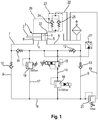
- FIGS. 1 . 2, 4 and 5 1 denotes a double-acting hydraulic cylinder which has a piston 3 provided with a piston rod 2.
- the piston 3 is longitudinally displaceably guided in a cylinder 4 and limited in this a cylindrical pressure chamber 5 and a hollow cylindrical pressure chamber 6. From the pressure chambers 5 and 6 lead pressure lines 7 and 8 to a damping circuit 9, in the targeted guidance and blocking of the pressure medium flow check valves 10, 11, 12 and 13 are arranged.
- the damping circuit 9 is bridged by a damper line 14, which receives an inverse proportional pressure relief valve 15 and a proportional pressure relief valve 16 connected downstream of this.
- Both proportional pressure relief valves 15 and 16 are pre-controlled via an electrical control current, wherein the corresponding control and control lines are not shown in detail.
- the proportional pressure relief valve 16 provides for a pressure change in the respective pressure line 7 or 8, from which it is flown, wherein this pressurization proportional to the electric current with which it is controlled, is changed. This electric current is preferably changed depending on the driving speed of a joint vehicle.
- the inverse proportional pressure relief valve 15 is also energized while driving and thus influenced together with the downstream of this proportional pressure relief valve 16, the pressure in the pressure lines 7 and 8. These pressure changes by means of the two proportional pressure relief valves 15 and 16 will be discussed in more detail below ,
- the check valves 11 and 12 are the pressure lines 7 and 8 in such a way with the damping circuit 9 that a pressure medium displaced from these pressure chambers 5 or 6 passes into the damper line 14.
- the check valves 10 and 13 block a flow of the pressure medium in the damping circuit 9 in a direction away from the damper line 14 direction.
- Each of one of the pressure chambers 5 or 6 displaced pressure medium is thus selectively fed to the damper line 14.
- a connecting line 17 which receives a serving as a safety valve pressure relief valve 18.
- a tank line 19 in which a biasing valve 20, which is also designed as a pressure relief valve, is arranged. This tank line 19 opens into an oil reservoir 21.
- the cylindrical pressure chamber 5 communicates via a suction line 22 with the oil reservoir 21, wherein a check valve unit 23 is located within the suction line 22.
- This check valve unit 23 consists of two pilot-operated check valves 24 and 25, which are actuated via a connected to the hollow cylindrical pressure chamber 6 control line 26 in its open position.
- a designated 27 pressure sensor is connected to the damping circuit 9 for monitoring the damping system.
- the function of the damping system is the following: During a straight ahead or cornering one with a joint arrangement, for example according to FIG. 6 , Provided articulated vehicle act pressure forces on the piston rod 2 and thus on the piston 3, so that in a corresponding manner, the pressure of the pressure chambers located in the pressure chambers 5 and 6 increases. If this pressure increase occurs, for example, in the pressure chamber 5, it is transmitted via the respective non-return valve 11 or 12 into the damping circuit 9 and is thus on the damper line 14 initially on the inverse proportional pressure relief valve 15 and performs depending on the height of the pressure to the Activity.
- the emerging from the inverse proportional pressure relief valve 15 pressure medium passes in a second stage to the downstream of this proportional pressure relief valve 16, which may be adjustable for example to a limiting pressure of 0 - 350 bar.
- proportional pressure relief valve is generally understood to mean pressure valves which continuously convert a variable input signal into a hydraulic output signal.
- the effluent from the damper line 14 pressure medium is thus finally passed through the proportional pressure relief valve 16 under pressure drop in the other line section of the damping circuit, where it passes through the check valve 10 in the hollow cylindrical pressure chamber 6.
- the check valve 11 blocks this line section from the pressurized line section of the damping circuit 9.
- a portion of the pressure medium can flow via the biasing valve 20 into the oil reservoir 21, which is required inter alia, since the volumes of the pressure chambers 5 and 6 differ from each other due to different cross-sectional areas.
- the pressure generated by the proportional pressure relief valve 16 in the pressure chamber 6 is transmitted via the control line 26 to the pilot-operated check valve unit 23. This establishes a connection between the oil reservoir 21 and the pressure chamber 5, so that a missing oil volume can be compensated. So that this amount of oil can be sucked from the oil reservoir 21, this is provided with a ventilation filter 28 having a ventilation via which a corresponding amount of air flows into the oil reservoir 21 or exits again from this.
- the inverse proportional pressure relief valve 15 is designed such that it is provided in the currentless state of one in the pilot control unit Proportional magnets or in case of failure of the electromagnetic actuation in the damping system can set a nominal pressure. It has a function according to which, with an increasing electrical input signal, the pressure generated in the respective pressure line 7 or 8 decreases, whereas this increases with a sinking single-gear signal. Thus, the effect of the inverse proportional pressure relief valve 15 of this in the damper line 14 subsequent proportional pressure relief valve 16 is opposite.
- these two proportional pressure-limiting valves 15 and 16 are matched with respect to their pressure profiles so that a specific damping pressure can be set via this unit as a function of the respective driving conditions of the articulated vehicle.
- the proportional pressure relief valve 16 have a controllable limiting pressure of 0-350 bar.
- the inverse proportional pressure relief valve 15 will have a lowest value of the limiting pressure, which is predetermined in order to drive the articulated vehicle safely to the next workshop during emergency operation of the damping system.
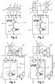
- the double-acting hydraulic cylinder 1 in an embodiment in which this has a further piston rod 2 '.
- the damping system consists only of the damping circuit 9 and the damper line 14 with the inverse proportional pressure relief valve 15 and the proportional pressure relief valve 16. In this case, so was both on a Connection line with a further pressure relief valve as well as on an oil reservoir with a tank line, a biasing valve and a device for sucking the pressure medium dispensed.
- the double-acting hydraulic cylinder 1 has two pressure chambers 6 and 6 ', which are both formed as a hollow cylinder.
- FIGS. 4 and 5 is in accordance with the FIG. 1 the pressure chamber 5 associated with a Nachsaug Rhein containing the already explained oil reservoir, the check valve unit 23 and the control line 26.
- the tank line with the biasing valve 20 disposed therein starts from the damper circuit 9, the tank line with the biasing valve 20 disposed therein.
- the electrically piloted proportional pressure relief valve 16 is arranged in the damper line 14.
- Both the inverse proportional pressure relief valve 15 and the electrically piloted proportional pressure relief valve 16 are arranged in the damper line 14. In both cases, was dispensed with the connecting line with the pressure relief valve.
- FIG. 6 shows a hinge assembly 29 for a non-illustrated articulated vehicle, which should preferably be designed as an articulated bus.
- This consists of a front vehicle part 30 and a rear vehicle part 31, which are connected to each other via a rotary joint 32.
- the articulated vehicle is driven by a non-illustrated drive axle, which is located in the rear part of the vehicle.
- the vehicle parts 30 and 31 are guided over the double-acting hydraulic cylinders 1 and 1 'of the above-described damping system to each other such that they are stabilized during a straight-ahead or cornering, so can not break out.
- a possible embodiment of the inverse proportional pressure relief valve 15 is a schematic representation of the FIG. 7 out. Thereafter, the proportional pressure relief valve 15, a housing 33, in which a main valve 34 and a pilot stage 35 are arranged.
- the pilot stage 35 has an armature 36 and coils 37, wherein the armature 36 with a seat valve body 38 which cooperates with a provided in the housing 33 valve seat 39.
- the main valve 34 consists of a displaceably guided in the housing 33 and supported by a valve spring 40 in this control piston 41.
- the control piston 41 is connected via a first port 42 of the housing 33 with the pressure from one of the pressure chambers (see FIG.
Landscapes
- Engineering & Computer Science (AREA)
- General Engineering & Computer Science (AREA)
- Mechanical Engineering (AREA)
- Chemical & Material Sciences (AREA)
- Combustion & Propulsion (AREA)
- Transportation (AREA)
- Vehicle Body Suspensions (AREA)
Description
Die Erfindung betrifft ein hydraulisches Dämpfungssystem zur Dämpfung von Schwenkbewegungen zweier zumindest mittelbar über ein Drehgelenk miteinander verbundener Fahrzeugteile mit zumindest einem als doppeltwirkender Hydraulikzylinder ausgebildeten Dämpfer, dessen druck- und saugseitige Druckräume über ein Proportional-Druckbegrenzungsventil miteinander verbunden sind.The invention relates to a hydraulic damping system for damping pivotal movements of two mutually at least indirectly connected via a rotary vehicle parts with at least one designed as a double-acting hydraulic cylinder damper whose pressure and suction pressure chambers are connected to each other via a proportional pressure relief valve.
Weiterhin betrifft die Erfindung ein Gelenkfahrzeug, bei dem zwei Fahrzeugteile zumindest mittelbar über ein Drehgelenk schwenkbar miteinander verbunden und mittels zumindest eines doppeltwirkenden Hydraulikzylinders eines Dämpfungssystems zueinander geführt sind, wobei in einer druck- und saugseitige Druckräume des zumindest einen Hydraulikzylinders verbindenden Dämpfungsleitung ein Proportional-Druckbegrenzungsventil angeordnet ist.Furthermore, the invention relates to an articulated vehicle in which two vehicle parts pivotally connected to each other at least indirectly via a rotary joint and guided by at least one double-acting hydraulic cylinder damping system to each other, wherein arranged in a pressure and suction pressure chambers of the at least one hydraulic cylinder connecting damping line, a proportional pressure relief valve is.
Gelenkfahrzeuge sind Kraftfahrzeuge, die vorzugsweise als Niederflur-Gelenkbusse ausgebildet sind, wobei diese ein, in Fahrtrichtung gesehen, vorderes Fahrzeugteil und ein hinteres Fahrzeugteil aufweisen. Zwischen diesen ist eine drehschemelartige Gelenkanordnung vorgesehen, die zur Verringerung des Wenderadius des entsprechenden Kraftfahrzeugs Knickwinkel zwischen den beiden Fahrzeugteilen zulassen und dabei eine im Wesentlichen vertikale Gelenkachse aufweisen. Darüber hinaus können im Rahmen der Kopplung der beiden Fahrzeugteile auch horizontal verlaufende Gelenkachsen vorgesehen sein, um die diese zueinander Nickbewegungen ausführen können.Articulated vehicles are motor vehicles, which are preferably designed as low-floor articulated buses, these having a seen in the direction of travel, front vehicle part and a rear vehicle part. Between these, a turntable-like joint arrangement is provided, which allow for reducing the turning radius of the corresponding motor vehicle bending angle between the two vehicle parts and thereby have a substantially vertical hinge axis. In addition, in the context of the coupling of the two vehicle parts and horizontally extending joint axes may be provided, around which these can execute pitching movements.
Für den Antrieb derartiger Gelenkfahrzeuge ist zumeist eine Antriebsachse vorgesehen, die als letzte Achse innerhalb des hinteren Fahrzeugteils angeordnet ist und somit das gesamte Gelenkfahrzeug, also auch den vorderen Fahrzeugteil über das Drehgelenk, schiebt. Ohne eine zwischen den beiden Fahrzeugteilen angeordnete, deren zueinander ausgeführte Bewegungen dämpfende Einrichtung, könnten schnell ausgeführte Knickbewegungen des Gelenkfahrzeugs zu dessen Ausbrechen führen. Aus diesem Grund ist zwischen den gelenkig zueinander geführten Teilen der Gelenkanordnung ein Dämpfungssystem angeordnet, das zumindest einen als Stoßdämpfer dienenden doppeltwirkenden Hydraulikzylinder aufweist. Der Ölstrom zwischen Druckräumen dieses Hydraulikzylinders wird gedrosselt, um eine Dämpfungswirkung zu erzielen.For the drive of such articulated vehicles usually a drive axle is provided, which is arranged as the last axis within the rear part of the vehicle and thus the entire articulated vehicle, including the front part of the vehicle on the hinge pushes. Without arranged between the two parts of the vehicle, their mutually executed movements damping device, quickly executed bending movements of the articulated vehicle could lead to its breaking. For this Reason is arranged between the articulated parts of the joint assembly guided a damping system having at least one serving as a shock absorber double-acting hydraulic cylinder. The flow of oil between the pressure chambers of this hydraulic cylinder is throttled to achieve a damping effect.
Ein hydraulisches Dämpfungssystem der im Oberbegriff der Patentansprüche 1, 9 und 12 angegebenen Gattung, das für ein Gelenkfahrzeug vorgesehen ist, geht aus der
Zwischen der Saug- und der Druckseite der Dämpfungsanordnung soll zusätzlich zu einem Proportional-Druckbegrenzungsventil ein parallel geschaltetes mechanisches Druckbegrenzungsventil vorgesehen sein. Diese beiden Druckbegrenzungsventile werden wahlweise über ein als 2/2-Wegeventil ausgebildetes Mehrwegeventil angesteuert. Im Normalbetrieb der Dämpfungsanordnung befindet sich das Mehrwegeventil in seiner Durchflussstellung, in der das Proportional-Druckbegrenzungsventil beaufschlagt wird. Bei einem Ausfall der Steuerung oder der Funktion des Proportional-Druckbegrenzungsventil, also im Notbetrieb, soll das elektromagnetisch betätigte Mehrwegeventil in eine Sperrstellung verschoben werden, so dass das in einer vor diesem abzweigenden Leitung angeordnete mechanisches Druckbegrenzungsventil mit Druckmittel aus einem der Druckräume beaufschlagt wird.Between the suction and the pressure side of the damping arrangement, a parallel-connected mechanical pressure relief valve should be provided in addition to a proportional pressure relief valve. These two pressure relief valves are selectively controlled via a designed as a 2/2-way valve multi-way valve. In normal operation of the damping arrangement, the multi-way valve is in its flow position, in which the proportional pressure relief valve is acted upon. In case of failure of the controller or the function of the proportional pressure relief valve, ie in emergency operation, the solenoid-operated multiway valve is to be moved into a blocking position, so that the arranged in a branching off this line mechanical pressure relief valve with pressure medium from one of the pressure chambers is acted upon.
Es ist Aufgabe der vorliegenden Erfindung, ein hydraulisches Dämpfungssystem der vorgenannten Gattung derart zu gestalten, dass dessen Funktion verbessert wird und dieses mit kostengünstigen Mitteln herstellbar ist.It is an object of the present invention to design a hydraulic damping system of the aforementioned type such that its function is improved and this can be produced with cost-effective means.
Diese Aufgabe wird, ausgehend von dem jeweiligen Oberbegriff der Patentansprüche 1, 9 und 12 durch deren kennzeichnende Merkmale gelöst. Vorteilhafte Ausgestaltungen sind in den von den Patentansprüchen 1 und 9 abhängigen Patentansprüchen wiedergegeben, welche jeweils für sich genommen oder in Kombination miteinander einen Aspekt der Erfindung darstellen können.This object is achieved on the basis of the respective preamble of
Danach ist ein hydraulisches Dämpfungssystem zur Dämpfung von Schwenkbewegungen zweier über ein Drehgelenk miteinander verbundener Fahrzeugteile mit zumindest einem als doppeltwirkender Hydraulikzylinder ausgebildeten Dämpfer vorgesehen. Dabei kann ein doppeltwirkender einen mit zwei Kolbenstangen versehenen Kolben aufweisen, wobei die jeweiligen vom Kolben abgewandten Enden der Kolbenstangen zumindest mittelbar mit den Fahrzeugteilen verbunden sind. Im Rahmen der Gelenkanordnung kann auch ein mit einer Zahnstange zusammenwirkendes Zahnrad vorgesehen sein, das drehfest mit dem drehbaren Gelenkteil verbunden ist. Die Zahnstange nimmt dabei den Kolben des doppeltwirkenden Hydraulikzylinders auf.Thereafter, a hydraulic damping system for damping pivotal movements of two interconnected via a rotary vehicle parts with at least one designed as a double-acting hydraulic cylinder damper is provided. In this case, a double-acting having a piston provided with two piston rods, wherein the respective ends facing away from the piston of the piston rods are at least indirectly connected to the vehicle parts. In the context of the joint arrangement may also be provided a cooperating with a rack gear, which is rotatably connected to the rotatable joint part. The rack absorbs the piston of the double-acting hydraulic cylinder.
Alternativ dazu können aber auch zwei doppeltwirkende Hydraulikzylinder mit jeweils einer Kolbenstange vorgesehen sein, wobei der jeweilige Zylinder mit dem einen Fahrzeugteil und die Kolbenstange mit einem Gelenkteil des anderen Fahrzeugteils verbunden sind. In diesem Fall ist jeweils ein kolbenseitiger Druckraum des einen Hydraulikzylinders mit einem kolbenstangenseitigen Druckraum des anderen Hydraulikzylinders verbunden.Alternatively, however, two double-acting hydraulic cylinders, each with a piston rod may be provided, wherein the respective cylinder with the one vehicle part and the piston rod are connected to a hinge part of the other vehicle part. In this case, each piston-side pressure chamber of a hydraulic cylinder is connected to a piston rod-side pressure chamber of the other hydraulic cylinder.
Die entsprechenden druck- und saugseitigen Druckräume sind bei beiden Ausführungen und Anordnungen des bzw. der Hydraulikzylinder über ein Proportional-Druckbegrenzungsventil miteinander verbunden. Dieses sorgt in dem Druckraum, aus dem Druckmittel verdrängt wird, für einen Druckaufbau und bei einem druckabhängigen Öffnen für einen gedämpften Druckabfall in der entsprechenden Dämpferleitung, so dass die Bewegung des oder der Kolben gedämpft wird.The corresponding pressure and suction pressure chambers are connected to each other in both designs and arrangements of the hydraulic cylinder or via a proportional pressure relief valve. This provides in the pressure chamber, is displaced from the pressure medium, for a pressure build-up and a pressure-dependent opening for a damped pressure drop in the corresponding damper line, so that the movement of the piston or is damped.
Dabei ist das Proportional-Druckbegrenzungsventil als elektrisch vorgesteuertes inverses Proportional-Druckbegrenzungsventil ausgebildet, mit dem im stromlosen Zustand eines Proportionalmagneten oder bei einem Ausfall der elektromagnetischen Betätigung im Dämpfungssystem ein Nenndruck einstellbar ist. Dieses inverse Proportional-Druckbegrenzungsventil weist somit eine Funktion auf, nach der bei steigendem elektrischen Eingangssignal der Druck absinkt, während dieser bei sinkendem Eingangssignal steigt. Beispielsweise kann bei einem Ausfall des Eingangssignals oder einem Defekt der elektromagnetischen Betätigung als Fail-Safe-Funktion der eingestellte Druck bis auf den Nenndruck ansteigen, der einen sicheren Notbetrieb des Gelenkfahrzeuges gewährleistet. Damit ist bei derartigen Defekten ein ausreichendes Dämpfungsverhalten des Dämpfungssystems erhalten, so dass das Gelenkfahrzeug seine Fahrt bis in eine Werkstatt fortsetzen kann.In this case, the proportional pressure relief valve is designed as an electrically pilot-controlled inverse proportional pressure relief valve with which a nominal pressure is adjustable in the de-energized state of a proportional solenoid or in case of failure of the electromagnetic actuation in the damping system. This inverse proportional pressure relief valve thus has a function after which when rising electrical input signal, the pressure drops as it rises with decreasing input signal. For example, in case of failure of the input signal or a defect of the electromagnetic actuator as a fail-safe function, the set pressure to increase to the nominal pressure, which ensures safe emergency operation of the articulated vehicle. For a sufficient damping behavior of the damping system is obtained in such defects, so that the articulated vehicle can continue its journey to a workshop.
Demgegenüber weist das Dämpfungssystem nach der
In weiterer Ausgestaltung der Erfindung ist vorgesehen, dass mit dem inversen Proportional-Druckbegrenzungsventil ein Proportional-Druckbegrenzungsventil in Reihe geschaltet ist, und dass in einem Notbetrieb des Dämpfungssystems ein hydraulischer Druck in dem jeweiligen Druckraum ausschließlich über das inverse Proportional-Druckbegrenzungsventil erzielbar ist. Der Notdämpfungsdruck muss bei einem Ausfall der elektrischen Steuerung auf ein Druckniveau abgesenkt werden können, um die Lenkbarkeit des Gelenkfahrzeugs zu gewährleisten. In diesem Betrieb des Fahrzeugs soll eine reduzierte Dämpfung der Bewegungen des Drehgelenks ermöglicht werden.In a further embodiment of the invention, it is provided that with the inverse proportional pressure relief valve, a proportional pressure relief valve is connected in series, and that in an emergency operation of the damping system, a hydraulic pressure in the respective pressure chamber can be achieved only via the inverse proportional pressure relief valve. The emergency damping pressure must be able to be lowered to a pressure level in case of failure of the electric control to ensure the steerability of the articulated vehicle. In this operation of the vehicle, a reduced damping of the movements of the swivel joint is to be made possible.
Aus diesem Grund sollen gemäß der Erfindung ein Proportional-Druckbegrenzungsventil, das vorzugsweise elektromagnetisch betätigt ist, mit dem inversen Proportional-Druckbegrenzungsventil in Reihe geschaltet werden. Beide Proportional-Druckbegrenzungsventile wirken logisch in einer "UND"-Verknüpfung zusammen, so dass sich die jeweils eingestellten Drücke addieren. Damit wird erreicht, dass sowohl bei Ausfall der Bordspannung als auch bei spezifikationsgemäßer elektrischer Ansteuerung der geforderte hydraulische Druck zu gewährleistet ist. Das elektrisch gesteuerte Proportional-Druckbegrenzungsventil wird dabei vorzugsweise fahrgeschwindigkeitsabhängig vorgesteuert.For this reason, according to the invention, a proportional pressure relief valve, which is preferably actuated electromagnetically, are connected in series with the inverse proportional pressure relief valve. Both Proportional pressure relief valves work logically in an "AND" combination, so that the respective set pressures add up. This ensures that both in case of failure of the on-board voltage as well as specified specification electrical control of the required hydraulic pressure is guaranteed. The electrically controlled proportional pressure relief valve is preferably pre-controlled as a function of driving speed.
Das inverse Proportional-Druckbegrenzungsventil wird im normalen Fahrbetrieb ebenfalls bestromt, und zwar derart, dass es bezogen auf das Proportional-Druckbegrenzungsventil eine inverse Steuerfunktion übernimmt. Wenn also der Steuerstrom hoch ist, werden das normale Proportional-Druckbegrenzungsventil auf einen hohen Druck und das inverse Proportional-Druckbegrenzungsventil auf einen niedrigen Druck eingestellt. Bei einem niedrigen Steuerstrom liegen die umgekehrten Druckverhältnisse vor. Eintrittsseitig der Anordnung der beiden Proportional-Druckbegrenzungsventile soll sich durch eine Addition beider Drücke ein Druckniveau einstellen, das dem für die Dämpfung geforderten Dämpfungsdruck, der im Hydraulikzylinder in jeder der beiden Bewegungsrichtungen des Kolbens wirkt, entspricht. Fällt aber die elektrische Steuerung aus, so gelangt das normale Proportional-Druckbegrenzungsventil in eine Stellung, in der nur ein sehr geringer oder kein Druck aufgebaut wird, während das ebenfalls stromlose inverse Proportional-Druckbegrenzungsventil einen Notdämpfungsdruck einstellt. Dabei kann das inverse Proportional-Druckbegrenzungsventil dem Proportional-Druckbegrenzungsventil vorgeschaltet sein.The inverse proportional pressure relief valve is also energized in normal driving, in such a way that it assumes an inverse control function based on the proportional pressure relief valve. Thus, when the control current is high, the normal proportional pressure relief valve is set to a high pressure and the inverse proportional pressure relief valve is set to a low pressure. At a low control current the reverse pressure conditions are present. On the inlet side of the arrangement of the two proportional pressure relief valves to set a pressure level by addition of both pressures, which corresponds to the required damping for the damping pressure acting in the hydraulic cylinder in each of the two directions of movement of the piston. But if the electrical control fails, then the normal proportional pressure relief valve enters a position in which only a very low or no pressure is built up, while the likewise de-energized inverse proportional pressure relief valve adjusts an emergency damping pressure. In this case, the inverse proportional pressure relief valve may be connected upstream of the proportional pressure relief valve.
Außerdem ist vorgesehen, dass das des inversen Proportional-Druckbegrenzungsventil eine Vorsteuerstufe aufweist, die bei einer Verringerung oder einem Ausfall des Steuerstromes in eine Sperr- oder Drosselstellung verstellt wird und einen Steuerdruck an einem Hauptkolben des inversen Proportional-Druckbegrenzungsventils aufbaut.It is also provided that the inverse proportional pressure relief valve has a pilot stage, which is adjusted at a reduction or a failure of the control current in a blocking or throttle position and builds up a control pressure to a main piston of the inverse proportional pressure relief valve.
In weiterer Ausgestaltung der Erfindung kann zur Begrenzung des Druckes in den Druckräumen und der an Kolbenstangen des zumindest einen Hydraulikzylinders wirkenden Kräfte zum inversen Proportional-Druckbegrenzungsventil ein Druckbegrenzungsventil parallel geschaltet sein. Dabei soll dieses als Sicherheitsventil dienende Druckbegrenzungsventil auf einen maximal zulässigen Druck des Dämpfungssystems eingestellt sein, der vorgegeben ist durch die Knicksicherheit der Kolbenstangen.In a further embodiment of the invention may be connected in parallel to limit the pressure in the pressure chambers and acting on piston rods of the at least one hydraulic cylinder forces to the inverse proportional pressure relief valve, a pressure relief valve. It should be set to serve as a safety valve pressure relief valve to a maximum allowable pressure of the damping system, which is specified by the buckling safety of the piston rods.
Vorzugsweise kann dabei ein Faktor 3 der Knicksicherheit berücksichtigt werden. Beispielsweise kann das elektromagnetisch gesteuerte Proportional-Druckbegrenzungsventil einen Bereich des jeweiligen Begrenzungsdrucks von 0 - 350 bar aufweisen, wobei sich durch Addition dieser Drücke zu den jeweils vom inversen Proportional-Druckbegrenzungsventil aufgebauten Drücken ein maximaler Dämpfungsdruck von weniger als 200 bar ergibt. Vorzugsweise ist das parallel geschaltete Druckbegrenzungsventil auf einen Öffnungsdruck von 200 bar eingestellt.Preferably, a factor of 3 buckling safety can be taken into account. For example, the electromagnetically controlled proportional pressure relief valve can have a range of the respective limiting pressure of 0-350 bar, whereby a maximum damping pressure of less than 200 bar results by adding these pressures to the pressures built up by the inverse proportional pressure limiting valve. Preferably, the parallel-connected pressure relief valve is set to an opening pressure of 200 bar.
Weiterhin kann austrittsseitig einer das inverse Proportional-Druckbegrenzungsventil und das Proportional-Druckbegrenzungsventil aufnehmenden Dämpfungsleitung von dieser eine an einen Tank angeschlossene ein Vorspannventil aufnehmende Tankleitung angeschlossen sein. Das Vorspannventil stellt in den Leitungsabschnitten, die jeweils mit dem sich vergrößernden Druckraum verbunden sind, einen Vorspanndruck her, der dazu führt, dass der Druckraum zwangsbefüllt wird. Damit wird Kavitation verhindert, die bei schnellen Bewegungen des im Hydraulikzylinder angeordneten Kolbens auftreten könnte.Furthermore, on the outlet side, a damping line accommodating the inverse proportional pressure relief valve and the proportional pressure limiting valve can be connected from this tank line connected to a tank to a biasing valve. The biasing valve establishes a bias pressure in the conduit sections, which are respectively connected to the increasing pressure chamber, which results in that the pressure chamber is forcibly filled. This prevents cavitation, which could occur during rapid movements of the piston arranged in the hydraulic cylinder.
Zusätzlich kann ein Nachsaugen von Druckflüssigkeit in zumindest einen der Druckräume dadurch erreicht werden, dass zumindest einer der Druckräume über zumindest ein entsperrbares Rückschlagventil mit einem Ölreservoir eines Tanks verbunden ist. Dabei kann das zumindest eine entsperrbare Rückschlagventil über eine an einen der Druckräume angeschlossene Steuerleitung in seine Öffnungsstellung betätigbar sein. Bei Druckräumen, die zum einen stirnseitig des Kolbens zylindrisch und zum anderen im Kolbenstangenbereich hohlzylindrisch ausgebildet sind, kann die Steuerleitung von dem hohlzylindrischen Steuerraum ausgehen. Der durch das Proportional-Druckbegrenzungsventil erzeugte Druck wird beispielsweise über den hohlzylindrischen Steuerraum und die Steuerleitung dem entsperrbaren Rückschlagventil zugeleitet, so dass dieses eine Verbindung zwischen dem Ausgleichsbehälter dienenden Tank und dem zylindrischen Druckraum herstellt und eine Ölvolumenstrom in den Druckraum gelangt.In addition, a sucking in of pressure fluid into at least one of the pressure chambers can be achieved by connecting at least one of the pressure chambers via at least one unlockable check valve to an oil reservoir of a tank. In this case, the at least one unlockable check valve can be actuated via a connected to one of the pressure chambers control line in its open position. In pressure chambers, which are cylindrical on one end side of the piston and the other in the piston rod area hollow cylindrical, the control line can emanate from the hollow cylindrical control chamber. The pressure generated by the proportional pressure relief valve is supplied to the pilot-operated check valve, for example, via the hollow cylindrical control chamber and the control line, so that this establishes a connection between the reservoir tank and the cylindrical pressure chamber and an oil flow into the pressure chamber.
Weiterhin wird die Aufgabe bei einem hydraulischen Dämpfungssystem zur Dämpfung von Schwenkbewegungen zweier über ein Drehgelenk zumindest mittelbar miteinander verbundener Fahrzeugteile mit zumindest einem als doppeltwirkender Hydraulikzylinder ausgebildeten Dämpfer, dessen druck- und saugseitige Druckräume über ein Proportional-Druckbegrenzungsventil miteinander verbunden sind, auch dadurch gelöst, dass zumindest einer der Druckräume über zumindest ein entsperrbares Rückschlagventil mit einem Ölreservoir eines Tanks verbunden ist. Eine entsprechende Möglichkeit für ein Nachsaugen von Druckmittel aus einem Ölreservoir soll folglich auch vorgesehen sein, wenn in der Dämpferleitung nur ein elektromagnetisch vorgesteuertes Proportional-Druckbegrenzungsventil angeordnet ist. Auch in diesem Fall kann austrittsseitig des Proportional-Druckbegrenzungsventils eine an den Tank angeschlossene ein Vorspannventil aufnehmende Rücklaufleitung angeschlossen sein. Auch mittels dieses Vorspannventils wird Kavitation im Dämpfungssystem verhindert.Furthermore, the object is in a hydraulic damping system for damping pivotal movements of two at least indirectly interconnected vehicle parts via a rotary joint with at least one designed as a double-acting hydraulic cylinder damper whose pressure and suction pressure chambers via a proportional pressure relief valve connected to each other, also solved in that at least one of the pressure chambers is connected via at least one pilot-operated check valve with an oil reservoir of a tank. A corresponding possibility for a Nachsaugen of pressure medium from an oil reservoir should therefore also be provided if in the damper line only an electromagnetically pilot operated proportional pressure relief valve is arranged. Also in this case may be connected to the tank connected to the tank a return valve receiving return line on the outlet side of the proportional pressure relief valve. Also by means of this preload valve cavitation is prevented in the damping system.
Schließlich soll bei einem Gelenkfahrzeug, bei dem zwei Fahrzeugteile zumindest mittelbar über ein Drehgelenk schwenkbar miteinander verbunden und mittels zumindest eines doppeltwirkenden Hydraulikzylinders eines Dämpfungssystems zueinander geführt sind, in einer druck- und saugseitige Druckräumen des zumindest einen Hydraulikzylinders verbindenden Dämpfungsleitung ein Proportional-Druckbegrenzungsventil angeordnet sein. Dabei soll das Dämpfungssystem nach einem der Patentansprüche 1 bis 11 ausgebildet sein.Finally, in an articulated vehicle in which two vehicle parts are pivotally connected to each other at least indirectly via a rotary joint and guided to each other by means of at least one double-acting hydraulic cylinder of a damping system to be arranged in a pressure and suction pressure chambers of the at least one hydraulic cylinder connecting the damping line, a proportional pressure relief valve. In this case, the damping system according to one of the
Die Erfindung ist nicht auf die angegebene Kombination der Merkmale der unabhängigen Patentansprüche 1, 9 und 12 mit den von diesen abhängigen Patentansprüchen beschränkt. Es ergeben sich darüber hinaus Möglichkeiten, einzelne Merkmale, soweit sie aus den Patentansprüchen, den Vorteilsangaben zu den Patentansprüchen, der nachfolgenden Beschreibung des Ausführungsbeispiels oder zumindest aus den Zeichnungen hervorgehen, miteinander zu kombinieren. Die Bezugnahme der Patentansprüche auf die Zeichnung durch entsprechende Verwendung vom Bezugszeichen soll den Schutzumfang der Patentansprüche nicht beschränken.The invention is not limited to the specified combination of the features of the
Zur weiteren Erläuterung der Erfindung wird auf die Zeichnung verwiesen, in der Ausführungsbeispiele dieser vereinfacht dargestellt sind. Es zeigen:
Figur 1- einen hydraulischen Schaltplan eines erfindungsgemäß ausgebildeten Dämpfungssystems mit einem doppeltwirkenden Hydraulikzylinder, einer ein inverses Proportional-Druckbegrenzungsventil sowie ein elektromagnetisch betätigtes Proportional-Druckbegrenzungsventil aufnehmende Dämpferleitung und einem parallel zur Dämpferleitung geschalteten Druckbegrenzungsventil,
Figur 2- eine zweite Ausführungsform eines Dämpfungssystems, bei dem das paraallel geschaltete Druckbegrenzungsventil entfallen ist und der doppeltwirkende Hydraulikzylinder zwei Kolbenstangen aufweist,
Figur 3- eine dritte Ausführungsform eines Dämpfungssystems, bei dem dieses zwei doppeltwirkende Hydraulikzylinder aufweist,
Figur 4- eine vierte Ausführungsform eines Dämpfungssystems, bei dem in Dämpferleitung nur ein elektromagnetisch betätigtes Proportional-Druckbegrenzungsventil angeordnet ist, wobei das Dämpfungssystem über ein Vorspannventil und entsperrbare Rückschlagventile mit einem Ölreservoir verbindbar ist,
Figur 5- eine fünfte Ausführungsform eines Dämpfungssystems, das im Wesentlichen dem nach der
Figur 4 entspricht, wobei aber in Übereinstimmung mit der Lösung nach derFigur 1 in der Dämpferleitung ein inverses Proportional-Druckbegrenzungsventil sowie ein elektromagnetisch betätigtes Proportional-Druckbegrenzungsventil angeordnet sind, Figur 6- als schematische Darstellung, ein zwischen zwei Fahrzeugteilen angeordnetes Drehgelenk und
- Figur 7
- als schematische Darstellung im Längsschnitt, ein inverses Proportional-Druckbegrenzungsventil.
- FIG. 1
- a hydraulic circuit diagram of an inventively designed damping system with a double-acting hydraulic cylinder, an inverse proportional pressure relief valve and an electromagnetically actuated proportional pressure relief valve receiving Damper line and a parallel to the damper line connected pressure relief valve,
- FIG. 2
- a second embodiment of a damping system, in which the parallel-connected pressure relief valve is omitted and the double-acting hydraulic cylinder has two piston rods,
- FIG. 3
- a third embodiment of a damping system in which it has two double-acting hydraulic cylinders,
- FIG. 4
- a fourth embodiment of a damping system, in which only one electromagnetically actuated proportional pressure relief valve is arranged in the damper line, wherein the damping system is connectable via a preload valve and pilot-operated check valves with an oil reservoir,
- FIG. 5
- a fifth embodiment of a damping system, which is substantially according to the
FIG. 4 corresponds, but in accordance with the solution according to theFIG. 1 an inverse proportional pressure limiting valve and an electromagnetically actuated proportional pressure limiting valve are arranged in the damper line, - FIG. 6
- as a schematic representation, arranged between two vehicle parts swivel and
- FIG. 7
- as a schematic representation in longitudinal section, an inverse proportional pressure relief valve.
In den
Weiterhin wird gemäß der
Das inverse Proportional-Druckbegrenzungsventil 15 wird im Fahrbetrieb ebenfalls bestromt und beeinflusst somit gemeinsam mit dem diesem nachgeschalteten Proportional-Druckbegrenzungsventil 16 den Druck in den Druckleitungen 7 und 8. Auf diese Druckveränderungen mittels der beiden Proportional-Druckbegrenzungsventile 15 und 16 wird nachfolgend noch näher eingegangen werden.The inverse proportional
Über die Rückschlagventile 11 und 12 stehen die Druckleitungen 7 und 8 derart mit dem Dämpfungskreis 9 in Verbindung, dass ein aus diesen Druckräumen 5 oder 6 verdrängtes Druckmittel in die Dämpferleitung 14 gelangt. Demgegenüber sperren die Rückschlagventile 10 und 13 eine Strömung des Druckmittels im Dämpfungskreis 9 in einer von der Dämpferleitung 14 wegweisenden Richtung. Das jeweils aus einem der Druckräume 5 oder 6 verdrängte Druckmittel wird also gezielt der Dämpferleitung 14 zugeführt. Weiterhin verläuft parallel zur Dämpferleitung 14 eine Verbindungsleitung 17, die ein als Sicherheitsventil dienendes Druckbegrenzungsventil 18 aufnimmt. Außerdem geht vom Dämpfungskreis 9, austrittsseitig der Dämpferleitung 14 eine Tankleitung 19 aus, in der ein Vorspannventil 20, das ebenfalls als Druckbegrenzungsventil ausgebildet ist, angeordnet ist. Diese Tankleitung 19 mündet in ein Ölreservoir 21.About the
Wie weiterhin aus der
Die Funktion des Dämpfungssystem ist folgende:
Während einer Geradeausfahrt oder Kurvenfahrt eines mit einer Gelenkanordnung, beispielsweise gemäß
During a straight ahead or cornering one with a joint arrangement, for example according to
Unter dem Begriff" Proportional-Druckbegrenzungsventil" versteht man im Allgemeinen Druckventile, die ein veränderliches Eingangssignal stufenlos in ein hydraulisches Ausgangssignal umsetzen. Das aus der Dämpferleitung 14 ausströmende Druckmittel wird also schließlich über das Proportional-Druckbegrenzungsventil 16 unter Druckabfall in den weiteren Leitungsabschnitt des Dämpfungskreises geleitet, wo es über das Rückschlagventil 10 in den hohlzylindrischen Druckraum 6 gelangt. Dabei sperrt das Rückschlagventil 11 diesen Leitungsabschnitt gegenüber dem unter Druck stehenden Leitungsabschnitt des Dämpfungskreises 9 ab. Ein Teil des Druckmittels kann dabei über das Vorspannventil 20 in das Ölreservoir 21 fließen, was unter anderem erforderlich ist, da die Volumina der Druckräume 5 und 6 aufgrund unterschiedlicher Querschnittsflächen voneinander abweichen.The term "proportional pressure relief valve" is generally understood to mean pressure valves which continuously convert a variable input signal into a hydraulic output signal. The effluent from the
Bewegt sich dagegen der Kolben 3 in Richtung des hohlzylindrischen Druckraumes 6, so wird in diesem, also auf der Seite der Kolbenstange 2 ein Volumenstrom erzeugt, der vollständig über das Rückschlagventil 11 in die Dämpferleitung 14 gelangt. Bei entsprechendem Druckanstieg auf einen elektrisch eingestellten Begrenzungsdruck durchströmt dieser Volumenstrom zunächst das bestromte inverse Proportional-Druckbegrenzungsventil 15 sowie anschließend bei Erreichen des entsprechend eingestellten Begrenzungsdrucks das Proportional-Druckbegrenzungsventil 16, um dann durch das geöffnete Rückschlagventil 13 und die Druckleitung 8 in den Druckraum 5 zu strömen.If, on the other hand, the
Der dabei durch das Proportional-Druckbegrenzungsventil 16 im Druckraum 6 erzeugte Druck wird über die Steuerleitung 26 auf die entsperrbarer Rückschlagventileinheit 23 übertragen. Diese stellt eine Verbindung zwischen dem Ölreservoir 21 und dem Druckraum 5 her, so dass ein fehlendes Ölvolumen ausgeglichen werden kann. Damit diese Ölmenge aus dem Ölreservoir 21 nachgesaugt werden kann, ist dieses mit einer ein Belüftungsfilter 28 aufweisenden Belüftung versehen, über die eine entsprechende Luftmenge in das Ölreservoir 21 einströmt oder wieder aus diesem austritt.The pressure generated by the proportional
Der positive Effekt dieser Art der Nachsaugung liegt darin, dass der Ölstrom in den Druckraum 5 nicht die Druckdifferenz eines federbelasteten Rückschlagventils überwinden muss, sondern dass dieser durch die zwangsweise geöffneten Rückschlagventile 24 und 25 fließt. Beim Nachsaugen müsste anderenfalls, also bei der Verwendung eines einfachen Rückschlagventils, das keine externe Betätigung aufweist, die Druckdifferenz im Rückschlagventil, die sich anteilig unter anderen aus dem Strömungswiderstand und dem Vorspanndruck der Rückschlagventil Feder addiert, überwunden werden. Der Strömungswiderstand hängt dabei vom Betrag des fließenden Ölvolumenstroms und der Viskosität des Hydraulikmediums ab.The positive effect of this type of Nachsaugung is that the flow of oil into the
Mit zunehmender Verfahrgeschwindigkeit des Kolbens 3 und zunehmender Viskosität, also insbesondere bei sinkender Öltemperatur, steigt die Druckdifferenz. Wenn die Druckdifferenz höher ist als der atmosphärische Druck im Ölreservoir, tritt aber Kavitation auf. Diese kann somit durch die Erfindung wirkungsvoll verhindert werden. Ein entsprechendes Nachsaugen in den Druckraum 6 über eine gesteuerte Ventileinheit ist nicht erforderlich, da dieser stets mit dem am Vorspannventil 20 eingestellten Druck zwangsbefüllt wird.With increasing travel speed of the
Das inverse Proportional-Druckbegrenzungsventil 15 ist derart ausgebildet, dass es im stromlosen Zustand eines in dessen Vorsteuereinheit vorgesehenen Proportionalmagneten oder bei einem Ausfall der elektromagnetischen Betätigung im Dämpfungssystem einen Nenndruck einstellen kann. Es weist eine Funktion auf, nach der bei einem steigenden elektrischen Eingangssignal der in der jeweiligen Druckleitung 7 oder 8 erzeugte Druck absinkt, wohingegen dieser bei einem sinkenden Einzelgangsignal steigt. Somit ist die Wirkung des inversen proportional-Druckbegrenzungsventils 15 der diesem in der Dämpferleitung 14 nachfolgenden Proportional-Druckbegrenzungsventils 16 entgegengesetzt.The inverse proportional
Erfindungsgemäß ist nun vorgesehen, dass diese beiden Proportional-Druckbegrenzungsventile 15 und 16 hinsichtlich ihrer Druckverläufe so aufeinander abgestimmt sind, dass sich über diese Einheit in Abhängigkeit von den jeweiligen Fahrzuständen des Gelenksfahrzeuges ein bestimmter Dämpfungsdruck einstellen lässt. Wie aus der
Im Normalbetrieb der Dämpfungseinrichtung sollen sich dagegen, wie bereits erläutert, die jeweiligen Begrenzungsdrücke beider Proportional-Druckbegrenzungsventile 15 und 16 addieren, so dass jeweils eine vorgegebene Höhe des Begrenzungsdruckes erreicht wird. Darüber hinaus ist es auch möglich, nur mittels des inversen Proportional-Druckbegrenzungsventils 15, also ohne das zusätzliche Proportional-Druckbegrenzungsventil 16 sowohl einen Normalbetrieb als auch einen Notbetrieb zu gewährleisten, wenn das inverse Proportional-Druckbegrenzungsventil 15 im Normalbetrieb auf einen sehr geringen Druck eingestellt werden kann, aber im Notbetrieb, also wenn es durch einen Defekt in einen stromlosen Zustand gelangt, den Nenndruck auf einen höheren Nenndruck als Fail-Safe-Funktion einstellt.In normal operation of the damping device should, however, as already explained, add the respective limiting pressures of both proportional
Im Unterschied zur
Die Anordnung nach der
Nach den
Die
Eine mögliche Ausbildung des inversen Proportional-Druckbegrenzungsventils 15 geht als schematische Darstellung aus der
- 11
- doppeltwirkender Hydraulikzylinderdouble-acting hydraulic cylinder
- 11
- doppeltwirkender Hydraulikzylinderdouble-acting hydraulic cylinder
- 22
- Kolbenstangepiston rod
- 2'2 '
- Kolbenstangepiston rod
- 33
- Kolbenpiston
- 3'3 '
- Kolbenpiston
- 44
- Zylindercylinder
- 4'4 '
- Zylindercylinder
- 55
- zylindrischer Druckraumcylindrical pressure chamber
- 5'5 '
- zylindrischer Druckraumcylindrical pressure chamber
- 66
- hohlzylindrischer Druckraumhollow cylindrical pressure chamber
- 6'6 '
- zylindrischer Druckraumcylindrical pressure chamber
- 77
- Druckleitungpressure line
- 88th
- Druckleitungpressure line
- 99
- Dämpfungskreisdamping circuit
- 1010
- Rückschlagventilcheck valve
- 1111
- Rückschlagventilcheck valve
- 1212
- Rückschlagventilcheck valve
- 1313
- Rückschlagventilcheck valve
- 1414
- Dämpferleitungdamper line
- 1515
- inverses Proportional-Druckbegrenzungsventilinverse proportional pressure relief valve
- 1616
- Proportional-DruckbegrenzungsventilProportional pressure relief valve
- 1717
- Verbindungsleitungconnecting line
- 1818
- DruckbegrenzungsventilPressure relief valve
- 1919
- Tankleitungtank line
- 2020
- VorspannventilPre-load valve
- 2121
- Ölreservoiroil reservoir
- 2222
- Nachsaugleitungsubsequent suction
- 2323
- RückschlagventileinheitCheck valve assembly
- 2424
- entsperrbares Rückschlagventilunlockable check valve
- 2525
- entsperrbares Rückschlagventilunlockable check valve
- 2626
- Steuerleitungcontrol line
- 2727
- Drucksensorpressure sensor
- 2828
- Belüftungsfilterventilation filter
- 2929
- Gelenkanordnungjoint arrangement
- 3030
- vorderes Fahrzeugteilfront vehicle part
- 3131
- hinteres Fahrzeugteilrear vehicle part
- 3232
- Drehgelenkswivel
- 3333
- Gehäuse von 15Housing of 15
- 3434
- Hauptventil von 15Main valve of 15
- 3535
- Vorsteuerstufe von 15Input tax level of 15
- 3636
- Anker von 35Anchor of 35
- 3737
- Spulen von 35Spools of 35
- 3838
- Sitzventilkörper von 35Seat valve body of 35
- 3939
- Ventilsitzvalve seat
- 4040
- Ventilfeder von 34Valve spring of 34
- 4141
- Steuerkolben von 34Spool of 34
- 4242
- erster Anschluss von 15first connection of 15
- 4343
- zweiter Anschluss von 15second port of 15
- 4444
- Steuerleitungcontrol line
Claims (12)
- A hydraulic damping system for damping pivotal movements of two vehicle parts (30 and 31) which are connected together at least indirectly by way of a rotary joint (32) with at least one damper which is in the form of a double-acting hydraulic cylinder (1, 1') and whose pressure-side and suction-side pressure chambers (5, 5', 6, 6') are connected together by way of a proportional pressure limiting valve, characterised in that the proportional pressure limiting valve is in the form of an electrically pilot-controlled inverse proportional pressure limiting valve (15), with which a nominal pressure can be set in the damping system in the current-less state of a proportional solenoid (36) or in the event of failure of the electromagnetic actuation.
- A hydraulic damping system according to claim 1 characterised in that a proportional pressure limiting valve (16) is connected in series with the inverse proportional pressure limiting valve (15) and in an emergency mode of the damping system a hydraulic pressure can be achieved in the respective pressure chamber (5, 5', 6, 6') exclusively by way of the inverse proportional pressure limiting valve (15).
- A hydraulic damping system according to claim 2 characterised in that the inverse proportional pressure limiting valve (15) is connected upstream of the proportional pressure limiting valve (16).
- A hydraulic damping system according to claim 1 characterised in that a pilot control stage (35) of the inverse proportional pressure limiting valve (15) is moved into a blocking position upon a reduction in the control current and builds up a control pressure at a main piston (41) of the inverse proportional pressure limiting valve (15).
- A hydraulic damping system according to claim 1 characterised in that to limit the pressure in the pressure chambers (5, 5', 6, 6') and the forces acting at piston rods (2, 2') of the at least one hydraulic cylinder (1, 1') a pressure limiting valve (18) is connected in parallel with the inverse proportional pressure limiting valve (15).
- A hydraulic damping system according to claim 1 characterised in that connected at the outlet side of a damper line (14) accommodating the inverse proportional pressure limiting valve (15) and the proportional pressure limiting valve (16) from same is a tank line (19) connected to an oil reservoir (21) and accommodating a biasing valve (20).
- A hydraulic damping system according to claim 1 characterised in that at least one of the pressure chambers (5) can be connected to an oil reservoir (21) by way of at least one releasable non-return valve (24, 25).
- A hydraulic damping system according to claim 7 characterised in that the at least one releasable non-return valve (24, 25) can be actuated into its open position by way of a control line (26) connected to one of the pressure chambers (6).
- A hydraulic damping system for damping pivotal movements of two vehicle parts (30 and 31) which are connected together at least indirectly by way of a rotary joint (32) with at least one damper which is in the form of a double-acting hydraulic cylinder (1, 1') and whose pressure-side and suction-side pressure chambers (5, 5', 6, 6') are connected together by way of a proportional pressure limiting valve, characterised in that at least one of the pressure chambers (5) can be connected to an oil reservoir (21) by way of at least one releasable non-return valve (24, 25).
- A hydraulic damping system according to claim 9 characterised in that the at least one releasable non-return valve (24, 25) can be actuated into its open position by way of a control line (26) connected to one of the pressure chambers (6).
- A hydraulic damping system according to claim 9 characterised in that the damping system is in accordance with one of claims 1 to 6.
- An articulated vehicle in which two vehicle parts (30 and 31) are pivotably connected together at least indirectly by way of a rotary joint (32) and are guided relative to each other by means of at least one double-acting hydraulic cylinder (1, 1') of a damping system, wherein arranged in a damper line (14) connecting pressure-side and suction-side pressure chambers (5, 5', 6, 6') of the at least one hydraulic cylinder (1, 1') is a proportional pressure limiting valve, characterised according to one of claims 1 to 11.
Applications Claiming Priority (1)
| Application Number | Priority Date | Filing Date | Title |
|---|---|---|---|
| DE102017100395.9A DE102017100395A1 (en) | 2017-01-11 | 2017-01-11 | Hydraulic damping system and articulated vehicle with such a damping system |
Publications (2)
| Publication Number | Publication Date |
|---|---|
| EP3348430A1 EP3348430A1 (en) | 2018-07-18 |
| EP3348430B1 true EP3348430B1 (en) | 2019-07-24 |
Family
ID=60674018
Family Applications (1)
| Application Number | Title | Priority Date | Filing Date |
|---|---|---|---|
| EP17208534.2A Active EP3348430B1 (en) | 2017-01-11 | 2017-12-19 | Hydraulic damping system and articulated vehicle with such a damping system |
Country Status (3)
| Country | Link |
|---|---|
| EP (1) | EP3348430B1 (en) |
| CA (1) | CA2991600C (en) |
| DE (1) | DE102017100395A1 (en) |
Cited By (1)
| Publication number | Priority date | Publication date | Assignee | Title |
|---|---|---|---|---|
| CN110966344A (en) * | 2019-12-27 | 2020-04-07 | 博迈科海洋工程股份有限公司 | Self-adjusting hydraulic vibration isolation system between HVAC machines |
Family Cites Families (3)
| Publication number | Priority date | Publication date | Assignee | Title |
|---|---|---|---|---|
| DE19716331A1 (en) * | 1997-04-18 | 1998-10-22 | Claas Saulgau Gmbh | Hydraulic control arrangement for at least one double-acting lifting cylinder |
| DE29822472U1 (en) | 1998-12-18 | 1999-04-01 | Hübner Gummi- und Kunststoff GmbH, 34123 Kassel | Hydraulic system for damping the rotary movement of a swivel joint between two vehicle parts of an articulated vehicle, e.g. an articulated bus |
| DE20317243U1 (en) * | 2003-11-06 | 2005-03-17 | Hemscheidt Fahrwerktech Gmbh | Valve system for hydraulic dampers used in swivel joints for articulated buses has proportional valve mounted in main current path, back-up valve in subsidiary current path being activated if power supply to first valve fails |
-
2017
- 2017-01-11 DE DE102017100395.9A patent/DE102017100395A1/en not_active Withdrawn
- 2017-12-19 EP EP17208534.2A patent/EP3348430B1/en active Active
-
2018
- 2018-01-10 CA CA2991600A patent/CA2991600C/en active Active
Non-Patent Citations (1)
| Title |
|---|
| None * |
Cited By (2)
| Publication number | Priority date | Publication date | Assignee | Title |
|---|---|---|---|---|
| CN110966344A (en) * | 2019-12-27 | 2020-04-07 | 博迈科海洋工程股份有限公司 | Self-adjusting hydraulic vibration isolation system between HVAC machines |
| CN110966344B (en) * | 2019-12-27 | 2021-07-20 | 博迈科海洋工程股份有限公司 | Self-adjusting hydraulic vibration isolation system between HVAC machines |
Also Published As
| Publication number | Publication date |
|---|---|
| CA2991600A1 (en) | 2018-07-11 |
| CA2991600C (en) | 2020-03-24 |
| EP3348430A1 (en) | 2018-07-18 |
| DE102017100395A1 (en) | 2018-07-12 |
Similar Documents
| Publication | Publication Date | Title |
|---|---|---|
| DE102014018788B3 (en) | Motor vehicle chassis | |
| EP0850151B1 (en) | Means for roll stabilisation of a vehicle | |
| DE102006002983B4 (en) | Active chassis system of a vehicle | |
| EP1609636B1 (en) | Hydraulic control device | |
| DE102005035171A1 (en) | Electrohydraulic steering | |
| DE102005006321A1 (en) | Valve, in particular proportional pressure relief valve | |
| WO2001064464A1 (en) | Hydraulic anti-roll system | |
| EP1761425B1 (en) | Hydraulic steering system protected against uncontrolled steering movements | |
| EP2463179B1 (en) | Valve assembly for controlling an additional steering system for multi-axle vehicles, in particular mobile cranes | |
| DE19646500C2 (en) | Device for stabilizing the roll of a vehicle | |
| EP3348430B1 (en) | Hydraulic damping system and articulated vehicle with such a damping system | |
| DE102008028170A1 (en) | steering system | |
| DE102006002959A1 (en) | Hydraulic system for use in vehicles, has current regulating piston, where height of application of pressure of current regulating piston, for adjustment to pressure is changed, according to flow against lateral pressure | |
| DE102004027971B4 (en) | Hydraulic steering device | |
| DE102014211582A1 (en) | Electronically slip-controllable vehicle brake system | |
| DE112004000076B4 (en) | Anti-roll system | |
| DE19629582A1 (en) | Device for stabilizing the roll of a vehicle | |
| EP1542878B1 (en) | Hydraulic stabilising device for vehicles | |
| DE102004051601A1 (en) | Roll stabilization system for double-track motor vehicle has hydraulic medium which is magnetorheologic fluid and valve which is magnetorheologic adjustable valve | |
| DE102016105159A1 (en) | Hydraulic system of a land or building usable vehicle | |
| DE102015120131B4 (en) | Steering system for operating a steering system | |
| DE102004040940A1 (en) | Module for a drive stabilizing system for a vehicle, has a fluid pressure actuator which is disconnected from the fluid supply by a locking unit | |
| EP2216235B1 (en) | Decoupling circuit of a hydraulic power steering | |
| EP2016317A1 (en) | Connector clamp with pressure valve | |
| DE19949152A1 (en) | Hydropneumatic suspension |
Legal Events
| Date | Code | Title | Description |
|---|---|---|---|
| PUAI | Public reference made under article 153(3) epc to a published international application that has entered the european phase |
Free format text: ORIGINAL CODE: 0009012 |
|
| STAA | Information on the status of an ep patent application or granted ep patent |
Free format text: STATUS: THE APPLICATION HAS BEEN PUBLISHED |
|
| AK | Designated contracting states |
Kind code of ref document: A1 Designated state(s): AL AT BE BG CH CY CZ DE DK EE ES FI FR GB GR HR HU IE IS IT LI LT LU LV MC MK MT NL NO PL PT RO RS SE SI SK SM TR |
|
| AX | Request for extension of the european patent |
Extension state: BA ME |
|
| STAA | Information on the status of an ep patent application or granted ep patent |
Free format text: STATUS: REQUEST FOR EXAMINATION WAS MADE |
|
| 17P | Request for examination filed |
Effective date: 20190118 |
|
| RBV | Designated contracting states (corrected) |
Designated state(s): AL AT BE BG CH CY CZ DE DK EE ES FI FR GB GR HR HU IE IS IT LI LT LU LV MC MK MT NL NO PL PT RO RS SE SI SK SM TR |
|
| GRAP | Despatch of communication of intention to grant a patent |
Free format text: ORIGINAL CODE: EPIDOSNIGR1 |
|
| STAA | Information on the status of an ep patent application or granted ep patent |
Free format text: STATUS: GRANT OF PATENT IS INTENDED |
|
| INTG | Intention to grant announced |
Effective date: 20190423 |
|
| GRAS | Grant fee paid |
Free format text: ORIGINAL CODE: EPIDOSNIGR3 |
|
| GRAA | (expected) grant |
Free format text: ORIGINAL CODE: 0009210 |
|
| STAA | Information on the status of an ep patent application or granted ep patent |
Free format text: STATUS: THE PATENT HAS BEEN GRANTED |
|
| AK | Designated contracting states |
Kind code of ref document: B1 Designated state(s): AL AT BE BG CH CY CZ DE DK EE ES FI FR GB GR HR HU IE IS IT LI LT LU LV MC MK MT NL NO PL PT RO RS SE SI SK SM TR |
|
| REG | Reference to a national code |
Ref country code: GB Ref legal event code: FG4D Free format text: NOT ENGLISH |
|
| REG | Reference to a national code |
Ref country code: CH Ref legal event code: EP |
|
| REG | Reference to a national code |
Ref country code: DE Ref legal event code: R096 Ref document number: 502017001847 Country of ref document: DE |
|
| REG | Reference to a national code |
Ref country code: AT Ref legal event code: REF Ref document number: 1157742 Country of ref document: AT Kind code of ref document: T Effective date: 20190815 |
|
| REG | Reference to a national code |
Ref country code: IE Ref legal event code: FG4D Free format text: LANGUAGE OF EP DOCUMENT: GERMAN |
|
| REG | Reference to a national code |
Ref country code: NL Ref legal event code: MP Effective date: 20190724 |
|
| REG | Reference to a national code |
Ref country code: LT Ref legal event code: MG4D |
|
| PG25 | Lapsed in a contracting state [announced via postgrant information from national office to epo] |
Ref country code: HR Free format text: LAPSE BECAUSE OF FAILURE TO SUBMIT A TRANSLATION OF THE DESCRIPTION OR TO PAY THE FEE WITHIN THE PRESCRIBED TIME-LIMIT Effective date: 20190724 Ref country code: NO Free format text: LAPSE BECAUSE OF FAILURE TO SUBMIT A TRANSLATION OF THE DESCRIPTION OR TO PAY THE FEE WITHIN THE PRESCRIBED TIME-LIMIT Effective date: 20191024 Ref country code: LT Free format text: LAPSE BECAUSE OF FAILURE TO SUBMIT A TRANSLATION OF THE DESCRIPTION OR TO PAY THE FEE WITHIN THE PRESCRIBED TIME-LIMIT Effective date: 20190724 Ref country code: PT Free format text: LAPSE BECAUSE OF FAILURE TO SUBMIT A TRANSLATION OF THE DESCRIPTION OR TO PAY THE FEE WITHIN THE PRESCRIBED TIME-LIMIT Effective date: 20191125 Ref country code: NL Free format text: LAPSE BECAUSE OF FAILURE TO SUBMIT A TRANSLATION OF THE DESCRIPTION OR TO PAY THE FEE WITHIN THE PRESCRIBED TIME-LIMIT Effective date: 20190724 Ref country code: BG Free format text: LAPSE BECAUSE OF FAILURE TO SUBMIT A TRANSLATION OF THE DESCRIPTION OR TO PAY THE FEE WITHIN THE PRESCRIBED TIME-LIMIT Effective date: 20191024 Ref country code: FI Free format text: LAPSE BECAUSE OF FAILURE TO SUBMIT A TRANSLATION OF THE DESCRIPTION OR TO PAY THE FEE WITHIN THE PRESCRIBED TIME-LIMIT Effective date: 20190724 Ref country code: SE Free format text: LAPSE BECAUSE OF FAILURE TO SUBMIT A TRANSLATION OF THE DESCRIPTION OR TO PAY THE FEE WITHIN THE PRESCRIBED TIME-LIMIT Effective date: 20190724 |
|
| PG25 | Lapsed in a contracting state [announced via postgrant information from national office to epo] |
Ref country code: GR Free format text: LAPSE BECAUSE OF FAILURE TO SUBMIT A TRANSLATION OF THE DESCRIPTION OR TO PAY THE FEE WITHIN THE PRESCRIBED TIME-LIMIT Effective date: 20191025 Ref country code: LV Free format text: LAPSE BECAUSE OF FAILURE TO SUBMIT A TRANSLATION OF THE DESCRIPTION OR TO PAY THE FEE WITHIN THE PRESCRIBED TIME-LIMIT Effective date: 20190724 Ref country code: AL Free format text: LAPSE BECAUSE OF FAILURE TO SUBMIT A TRANSLATION OF THE DESCRIPTION OR TO PAY THE FEE WITHIN THE PRESCRIBED TIME-LIMIT Effective date: 20190724 Ref country code: ES Free format text: LAPSE BECAUSE OF FAILURE TO SUBMIT A TRANSLATION OF THE DESCRIPTION OR TO PAY THE FEE WITHIN THE PRESCRIBED TIME-LIMIT Effective date: 20190724 Ref country code: RS Free format text: LAPSE BECAUSE OF FAILURE TO SUBMIT A TRANSLATION OF THE DESCRIPTION OR TO PAY THE FEE WITHIN THE PRESCRIBED TIME-LIMIT Effective date: 20190724 Ref country code: IS Free format text: LAPSE BECAUSE OF FAILURE TO SUBMIT A TRANSLATION OF THE DESCRIPTION OR TO PAY THE FEE WITHIN THE PRESCRIBED TIME-LIMIT Effective date: 20191124 |
|
| PG25 | Lapsed in a contracting state [announced via postgrant information from national office to epo] |
Ref country code: TR Free format text: LAPSE BECAUSE OF FAILURE TO SUBMIT A TRANSLATION OF THE DESCRIPTION OR TO PAY THE FEE WITHIN THE PRESCRIBED TIME-LIMIT Effective date: 20190724 |
|
| PG25 | Lapsed in a contracting state [announced via postgrant information from national office to epo] |
Ref country code: DK Free format text: LAPSE BECAUSE OF FAILURE TO SUBMIT A TRANSLATION OF THE DESCRIPTION OR TO PAY THE FEE WITHIN THE PRESCRIBED TIME-LIMIT Effective date: 20190724 Ref country code: IT Free format text: LAPSE BECAUSE OF FAILURE TO SUBMIT A TRANSLATION OF THE DESCRIPTION OR TO PAY THE FEE WITHIN THE PRESCRIBED TIME-LIMIT Effective date: 20190724 Ref country code: EE Free format text: LAPSE BECAUSE OF FAILURE TO SUBMIT A TRANSLATION OF THE DESCRIPTION OR TO PAY THE FEE WITHIN THE PRESCRIBED TIME-LIMIT Effective date: 20190724 Ref country code: RO Free format text: LAPSE BECAUSE OF FAILURE TO SUBMIT A TRANSLATION OF THE DESCRIPTION OR TO PAY THE FEE WITHIN THE PRESCRIBED TIME-LIMIT Effective date: 20190724 Ref country code: PL Free format text: LAPSE BECAUSE OF FAILURE TO SUBMIT A TRANSLATION OF THE DESCRIPTION OR TO PAY THE FEE WITHIN THE PRESCRIBED TIME-LIMIT Effective date: 20190724 |
|
| PG25 | Lapsed in a contracting state [announced via postgrant information from national office to epo] |
Ref country code: IS Free format text: LAPSE BECAUSE OF FAILURE TO SUBMIT A TRANSLATION OF THE DESCRIPTION OR TO PAY THE FEE WITHIN THE PRESCRIBED TIME-LIMIT Effective date: 20200224 Ref country code: SK Free format text: LAPSE BECAUSE OF FAILURE TO SUBMIT A TRANSLATION OF THE DESCRIPTION OR TO PAY THE FEE WITHIN THE PRESCRIBED TIME-LIMIT Effective date: 20190724 Ref country code: CZ Free format text: LAPSE BECAUSE OF FAILURE TO SUBMIT A TRANSLATION OF THE DESCRIPTION OR TO PAY THE FEE WITHIN THE PRESCRIBED TIME-LIMIT Effective date: 20190724 Ref country code: SM Free format text: LAPSE BECAUSE OF FAILURE TO SUBMIT A TRANSLATION OF THE DESCRIPTION OR TO PAY THE FEE WITHIN THE PRESCRIBED TIME-LIMIT Effective date: 20190724 |
|
| REG | Reference to a national code |
Ref country code: DE Ref legal event code: R097 Ref document number: 502017001847 Country of ref document: DE |
|
| PLBE | No opposition filed within time limit |
Free format text: ORIGINAL CODE: 0009261 |
|
| STAA | Information on the status of an ep patent application or granted ep patent |
Free format text: STATUS: NO OPPOSITION FILED WITHIN TIME LIMIT |
|
| PG2D | Information on lapse in contracting state deleted |
Ref country code: IS |
|
| 26N | No opposition filed |
Effective date: 20200603 |
|
| REG | Reference to a national code |
Ref country code: BE Ref legal event code: MM Effective date: 20191231 |
|
| PG25 | Lapsed in a contracting state [announced via postgrant information from national office to epo] |
Ref country code: SI Free format text: LAPSE BECAUSE OF FAILURE TO SUBMIT A TRANSLATION OF THE DESCRIPTION OR TO PAY THE FEE WITHIN THE PRESCRIBED TIME-LIMIT Effective date: 20190724 Ref country code: MC Free format text: LAPSE BECAUSE OF FAILURE TO SUBMIT A TRANSLATION OF THE DESCRIPTION OR TO PAY THE FEE WITHIN THE PRESCRIBED TIME-LIMIT Effective date: 20190724 |
|
| PG25 | Lapsed in a contracting state [announced via postgrant information from national office to epo] |
Ref country code: IE Free format text: LAPSE BECAUSE OF NON-PAYMENT OF DUE FEES Effective date: 20191219 Ref country code: FR Free format text: LAPSE BECAUSE OF NON-PAYMENT OF DUE FEES Effective date: 20191231 Ref country code: LU Free format text: LAPSE BECAUSE OF NON-PAYMENT OF DUE FEES Effective date: 20191219 |
|
| PG25 | Lapsed in a contracting state [announced via postgrant information from national office to epo] |
Ref country code: BE Free format text: LAPSE BECAUSE OF NON-PAYMENT OF DUE FEES Effective date: 20191231 |
|
| PG25 | Lapsed in a contracting state [announced via postgrant information from national office to epo] |
Ref country code: CY Free format text: LAPSE BECAUSE OF FAILURE TO SUBMIT A TRANSLATION OF THE DESCRIPTION OR TO PAY THE FEE WITHIN THE PRESCRIBED TIME-LIMIT Effective date: 20190724 |
|
| PG25 | Lapsed in a contracting state [announced via postgrant information from national office to epo] |
Ref country code: HU Free format text: LAPSE BECAUSE OF FAILURE TO SUBMIT A TRANSLATION OF THE DESCRIPTION OR TO PAY THE FEE WITHIN THE PRESCRIBED TIME-LIMIT; INVALID AB INITIO Effective date: 20171219 Ref country code: MT Free format text: LAPSE BECAUSE OF FAILURE TO SUBMIT A TRANSLATION OF THE DESCRIPTION OR TO PAY THE FEE WITHIN THE PRESCRIBED TIME-LIMIT Effective date: 20190724 |
|
| REG | Reference to a national code |
Ref country code: CH Ref legal event code: PL |
|
| PG25 | Lapsed in a contracting state [announced via postgrant information from national office to epo] |
Ref country code: CH Free format text: LAPSE BECAUSE OF NON-PAYMENT OF DUE FEES Effective date: 20201231 Ref country code: LI Free format text: LAPSE BECAUSE OF NON-PAYMENT OF DUE FEES Effective date: 20201231 |
|
| PG25 | Lapsed in a contracting state [announced via postgrant information from national office to epo] |
Ref country code: MK Free format text: LAPSE BECAUSE OF FAILURE TO SUBMIT A TRANSLATION OF THE DESCRIPTION OR TO PAY THE FEE WITHIN THE PRESCRIBED TIME-LIMIT Effective date: 20190724 |
|
| GBPC | Gb: european patent ceased through non-payment of renewal fee |
Effective date: 20211219 |
|
| PG25 | Lapsed in a contracting state [announced via postgrant information from national office to epo] |
Ref country code: GB Free format text: LAPSE BECAUSE OF NON-PAYMENT OF DUE FEES Effective date: 20211219 |
|
| P01 | Opt-out of the competence of the unified patent court (upc) registered |
Effective date: 20230516 |
|
| PGFP | Annual fee paid to national office [announced via postgrant information from national office to epo] |
Ref country code: DE Payment date: 20231214 Year of fee payment: 7 |
|
| REG | Reference to a national code |
Ref country code: AT Ref legal event code: MM01 Ref document number: 1157742 Country of ref document: AT Kind code of ref document: T Effective date: 20221219 |
|
| PG25 | Lapsed in a contracting state [announced via postgrant information from national office to epo] |
Ref country code: AT Free format text: LAPSE BECAUSE OF NON-PAYMENT OF DUE FEES Effective date: 20221219 |
|
| PG25 | Lapsed in a contracting state [announced via postgrant information from national office to epo] |
Ref country code: AT Free format text: LAPSE BECAUSE OF NON-PAYMENT OF DUE FEES Effective date: 20221219 |