EP1759256B1 - Elektrisch ansteuerbares ventil - Google Patents
Elektrisch ansteuerbares ventil Download PDFInfo
- Publication number
- EP1759256B1 EP1759256B1 EP20050752826 EP05752826A EP1759256B1 EP 1759256 B1 EP1759256 B1 EP 1759256B1 EP 20050752826 EP20050752826 EP 20050752826 EP 05752826 A EP05752826 A EP 05752826A EP 1759256 B1 EP1759256 B1 EP 1759256B1
- Authority
- EP
- European Patent Office
- Prior art keywords
- valve
- section
- valve body
- opening cross
- valve opening
- Prior art date
- Legal status (The legal status is an assumption and is not a legal conclusion. Google has not performed a legal analysis and makes no representation as to the accuracy of the status listed.)
- Not-in-force
Links
- 239000012530 fluid Substances 0.000 claims description 16
- 230000006835 compression Effects 0.000 description 10
- 238000007906 compression Methods 0.000 description 10
- 230000005284 excitation Effects 0.000 description 8
- 238000010586 diagram Methods 0.000 description 3
- 239000006096 absorbing agent Substances 0.000 description 2
- 238000013459 approach Methods 0.000 description 2
- 230000001105 regulatory effect Effects 0.000 description 2
- 238000007789 sealing Methods 0.000 description 2
- 230000035939 shock Effects 0.000 description 2
- 238000011144 upstream manufacturing Methods 0.000 description 2
- 206010052128 Glare Diseases 0.000 description 1
- 238000006073 displacement reaction Methods 0.000 description 1
- 230000000694 effects Effects 0.000 description 1
- 230000003993 interaction Effects 0.000 description 1
- 230000002093 peripheral effect Effects 0.000 description 1
Images

Classifications
-
- B—PERFORMING OPERATIONS; TRANSPORTING
- B60—VEHICLES IN GENERAL
- B60T—VEHICLE BRAKE CONTROL SYSTEMS OR PARTS THEREOF; BRAKE CONTROL SYSTEMS OR PARTS THEREOF, IN GENERAL; ARRANGEMENT OF BRAKING ELEMENTS ON VEHICLES IN GENERAL; PORTABLE DEVICES FOR PREVENTING UNWANTED MOVEMENT OF VEHICLES; VEHICLE MODIFICATIONS TO FACILITATE COOLING OF BRAKES
- B60T8/00—Arrangements for adjusting wheel-braking force to meet varying vehicular or ground-surface conditions, e.g. limiting or varying distribution of braking force
- B60T8/32—Arrangements for adjusting wheel-braking force to meet varying vehicular or ground-surface conditions, e.g. limiting or varying distribution of braking force responsive to a speed condition, e.g. acceleration or deceleration
- B60T8/34—Arrangements for adjusting wheel-braking force to meet varying vehicular or ground-surface conditions, e.g. limiting or varying distribution of braking force responsive to a speed condition, e.g. acceleration or deceleration having a fluid pressure regulator responsive to a speed condition
- B60T8/36—Arrangements for adjusting wheel-braking force to meet varying vehicular or ground-surface conditions, e.g. limiting or varying distribution of braking force responsive to a speed condition, e.g. acceleration or deceleration having a fluid pressure regulator responsive to a speed condition including a pilot valve responding to an electromagnetic force
- B60T8/3615—Electromagnetic valves specially adapted for anti-lock brake and traction control systems
- B60T8/3655—Continuously controlled electromagnetic valves
- B60T8/366—Valve details
- B60T8/367—Seat valves, e.g. poppet valves
-
- B—PERFORMING OPERATIONS; TRANSPORTING
- B60—VEHICLES IN GENERAL
- B60T—VEHICLE BRAKE CONTROL SYSTEMS OR PARTS THEREOF; BRAKE CONTROL SYSTEMS OR PARTS THEREOF, IN GENERAL; ARRANGEMENT OF BRAKING ELEMENTS ON VEHICLES IN GENERAL; PORTABLE DEVICES FOR PREVENTING UNWANTED MOVEMENT OF VEHICLES; VEHICLE MODIFICATIONS TO FACILITATE COOLING OF BRAKES
- B60T8/00—Arrangements for adjusting wheel-braking force to meet varying vehicular or ground-surface conditions, e.g. limiting or varying distribution of braking force
- B60T8/32—Arrangements for adjusting wheel-braking force to meet varying vehicular or ground-surface conditions, e.g. limiting or varying distribution of braking force responsive to a speed condition, e.g. acceleration or deceleration
- B60T8/34—Arrangements for adjusting wheel-braking force to meet varying vehicular or ground-surface conditions, e.g. limiting or varying distribution of braking force responsive to a speed condition, e.g. acceleration or deceleration having a fluid pressure regulator responsive to a speed condition
- B60T8/36—Arrangements for adjusting wheel-braking force to meet varying vehicular or ground-surface conditions, e.g. limiting or varying distribution of braking force responsive to a speed condition, e.g. acceleration or deceleration having a fluid pressure regulator responsive to a speed condition including a pilot valve responding to an electromagnetic force
- B60T8/3615—Electromagnetic valves specially adapted for anti-lock brake and traction control systems
- B60T8/363—Electromagnetic valves specially adapted for anti-lock brake and traction control systems in hydraulic systems
- B60T8/365—Electromagnetic valves specially adapted for anti-lock brake and traction control systems in hydraulic systems combining a plurality of functions in one unit, e.g. pressure relief
-
- B—PERFORMING OPERATIONS; TRANSPORTING
- B60—VEHICLES IN GENERAL
- B60T—VEHICLE BRAKE CONTROL SYSTEMS OR PARTS THEREOF; BRAKE CONTROL SYSTEMS OR PARTS THEREOF, IN GENERAL; ARRANGEMENT OF BRAKING ELEMENTS ON VEHICLES IN GENERAL; PORTABLE DEVICES FOR PREVENTING UNWANTED MOVEMENT OF VEHICLES; VEHICLE MODIFICATIONS TO FACILITATE COOLING OF BRAKES
- B60T8/00—Arrangements for adjusting wheel-braking force to meet varying vehicular or ground-surface conditions, e.g. limiting or varying distribution of braking force
- B60T8/32—Arrangements for adjusting wheel-braking force to meet varying vehicular or ground-surface conditions, e.g. limiting or varying distribution of braking force responsive to a speed condition, e.g. acceleration or deceleration
- B60T8/34—Arrangements for adjusting wheel-braking force to meet varying vehicular or ground-surface conditions, e.g. limiting or varying distribution of braking force responsive to a speed condition, e.g. acceleration or deceleration having a fluid pressure regulator responsive to a speed condition
- B60T8/36—Arrangements for adjusting wheel-braking force to meet varying vehicular or ground-surface conditions, e.g. limiting or varying distribution of braking force responsive to a speed condition, e.g. acceleration or deceleration having a fluid pressure regulator responsive to a speed condition including a pilot valve responding to an electromagnetic force
- B60T8/3615—Electromagnetic valves specially adapted for anti-lock brake and traction control systems
- B60T8/3655—Continuously controlled electromagnetic valves
- B60T8/366—Valve details
- B60T8/3665—Sliding valves
-
- Y—GENERAL TAGGING OF NEW TECHNOLOGICAL DEVELOPMENTS; GENERAL TAGGING OF CROSS-SECTIONAL TECHNOLOGIES SPANNING OVER SEVERAL SECTIONS OF THE IPC; TECHNICAL SUBJECTS COVERED BY FORMER USPC CROSS-REFERENCE ART COLLECTIONS [XRACs] AND DIGESTS
- Y10—TECHNICAL SUBJECTS COVERED BY FORMER USPC
- Y10T—TECHNICAL SUBJECTS COVERED BY FORMER US CLASSIFICATION
- Y10T137/00—Fluid handling
- Y10T137/8593—Systems
- Y10T137/86493—Multi-way valve unit
- Y10T137/86879—Reciprocating valve unit
-
- Y—GENERAL TAGGING OF NEW TECHNOLOGICAL DEVELOPMENTS; GENERAL TAGGING OF CROSS-SECTIONAL TECHNOLOGIES SPANNING OVER SEVERAL SECTIONS OF THE IPC; TECHNICAL SUBJECTS COVERED BY FORMER USPC CROSS-REFERENCE ART COLLECTIONS [XRACs] AND DIGESTS
- Y10—TECHNICAL SUBJECTS COVERED BY FORMER USPC
- Y10T—TECHNICAL SUBJECTS COVERED BY FORMER US CLASSIFICATION
- Y10T137/00—Fluid handling
- Y10T137/8593—Systems
- Y10T137/86919—Sequentially closing and opening alternately seating flow controllers
-
- Y—GENERAL TAGGING OF NEW TECHNOLOGICAL DEVELOPMENTS; GENERAL TAGGING OF CROSS-SECTIONAL TECHNOLOGIES SPANNING OVER SEVERAL SECTIONS OF THE IPC; TECHNICAL SUBJECTS COVERED BY FORMER USPC CROSS-REFERENCE ART COLLECTIONS [XRACs] AND DIGESTS
- Y10—TECHNICAL SUBJECTS COVERED BY FORMER USPC
- Y10T—TECHNICAL SUBJECTS COVERED BY FORMER US CLASSIFICATION
- Y10T137/00—Fluid handling
- Y10T137/8593—Systems
- Y10T137/86928—Sequentially progressive opening or closing of plural valves
- Y10T137/86936—Pressure equalizing or auxiliary shunt flow
- Y10T137/86944—One valve seats against other valve [e.g., concentric valves]
- Y10T137/86976—First valve moves second valve
-
- Y—GENERAL TAGGING OF NEW TECHNOLOGICAL DEVELOPMENTS; GENERAL TAGGING OF CROSS-SECTIONAL TECHNOLOGIES SPANNING OVER SEVERAL SECTIONS OF THE IPC; TECHNICAL SUBJECTS COVERED BY FORMER USPC CROSS-REFERENCE ART COLLECTIONS [XRACs] AND DIGESTS
- Y10—TECHNICAL SUBJECTS COVERED BY FORMER USPC
- Y10T—TECHNICAL SUBJECTS COVERED BY FORMER US CLASSIFICATION
- Y10T137/00—Fluid handling
- Y10T137/8593—Systems
- Y10T137/86928—Sequentially progressive opening or closing of plural valves
- Y10T137/87016—Lost motion
- Y10T137/8704—First valve actuates second valve
Definitions
- the invention relates to an electrically controllable valve, in particular for use in a shock absorber, according to the preamble of patent claim 1.
- the object of the invention is to design a valve of the specified type with the least possible effort such that using a simple, reliable means a pressure control and pressure limiting function comes about.
- FIG. 1 shows the Fig. 1 in longitudinal section an electrically actuated valve, which is preferably used to control a shock absorber in a motor vehicle.
- the valve consists of an electric actuator 1, a directly actuated by the actuator 1 first valve body 2, which cooperates with a control edge 3 in the valve housing 4.
- the interaction of the first valve body 2 with the control edge 3 results in a variably adjustable first valve opening cross section A1 through which a regulated fluid flow (so-called primary flow) passes in the direction of the valve outlet channel 16 located in the region of the valve body 2.
- a second valve opening cross-section A2 between the conically widened inner portion of the valve housing 4 and an annular disk-shaped second valve body 6 is provided in front of the first valve opening cross-section A1, which is actuated by the actuator 1 via a ram-shaped extension 7 attached to the first valve body 2 whose outer diameter corresponds to the outer diameter of the valve body first valve body 2 corresponds.
- the variable second valve opening cross section A2 is thus upstream of the first valve opening cross section A1 in a series connection to the first valve opening cross section A1, wherein both valve opening cross sections A1, A2 are reciprocally open and closed reciprocally by means of the first valve body 2.
- a third valve cross section A3 normally closed by the end face of the extension 7 is provided.
- a valve inlet channel 17 opens into the valve housing 4 upstream of the second valve body 6.
- the first valve body 2 is preferably designed as a valve piston guided in the valve housing 4, which is always lifted off the control edge 3 by means of a return spring 5 acting on the second valve body 6 in the electrically de-energized state of the actuator 1, so that the first valve opening cross section A1 is at least partially open.
- a return spring 5 acting on the second valve body 6 in the electrically de-energized state of the actuator 1, so that the first valve opening cross section A1 is at least partially open.
- the return spring 5 is disposed between the second valve body 6 and the valve housing 4, so that in the non-energized state of the actuator 1, the second valve body 6 always on the housing stage 14 (cone stage of the valve housing 4) remains sealingly and exclusively executed in the present embodiment as a peripheral notch aperture 8 of the second valve body 6 is released, so that in the non-energized state of the actuator 1, a slight passage in the region of the third valve opening cross section A3 is present to ensure the cross-section of the aperture 8 depending hydraulic connection between the valve inlet and outlet channel 17, 16 ,
- a compression spring 9 which acts only slightly counteracts the hydraulic pressure in the valve inlet channel 17 and the return spring 5.
- the first valve body 2 On its side remote from the extension 7 end face on an actuating pin 10.
- the spring stop 11 Under the permanent action of the compression spring 9, the spring stop 11 is supported either on the inner wall of the valve housing 4 or on a stop shoulder of a pressure piece 12 connected to the actuating pin 10.
- the pressure piece 12th is sealed within the valve housing 4 and protrudes with its remote from the spring stop 11 end face in a preferred embodiment in the electromagnetic actuator 1, which consists of a pressure piece 12 actuated armature 13.
- the first valve body 2 can also be designed as a seat valve instead of a slide valve.
- the first valve body 2 as in the valve housing 4 guided plunger is preferably located on the outer circumference of the plunger a pressure distribution groove 15 through which the fluid passes for pressure equalization in the space of the valve housing 4, in which the compression spring 9 is located.
- the sealing of this space in the direction of the actuator takes place in the simplest case by the metallic sealing pressure piece 12, which is inevitably acted upon by the fluid pressure.
- FIG. 1 shows the valve with the features underlying the invention in a first pressure control position in which the excitation current corresponds to the maximum electrical drive current of the valve housing 4 attached valve spool, whereby the adjusted fluid flow can flow through the valve monodirectional under high fluid pressure.
- the maximum excitation current imax the armature 13 moves namely the pressure from the pad 12, the spring stop 11, the compression spring 9, the first and second valve piston 2, 6 and the extension 7 existing assembly against the action of the return spring 5 to the left, causing the second valve piston 6 away from the housing stage 14, while the first valve piston 2 of the control edge 3 for pressure control approaches.
- the Fig. 1a shows the pressure control characteristic for the in Fig. 1 pictured pressure control function. This is in Fig. 1a plotted on the ordinate of the diagram of the pressure increase p and along the abscissa of the volume flow Q, which is characterized as a result of the high excitation current imax the desired high volume flow Q of the fluid by a steep pressure increase p of the hydraulic pressure.
- FIG. 2 shows differing from FIG. 1 the valve in a control position in which the excitation current corresponds to the minimum electrical drive current of the valve spool 12.
- the minimum excitation current imin shifts the armature 13 from the pressure piece 12, the spring stop 11, the compression spring 9, the first and second valve piston 2 and the extension 7 existing assembly against the action of the return spring 5 only slightly to the left, causing the second Valve piston 6 only slightly removed from the housing stage 14, while the pressure control of the first valve piston 2 of the control edge 3 by the amount traveled distance of the second valve piston 6 approaches.
- this pressure control position thus follows in the diagram Fig. 2a illustrated pressure control characteristic, from which a shallow pressure increase with increasing volume flow Q can be seen.
- the armature 13 remains in this case in its position remote from the pressure piece 12, whereby due to the action of the return spring 5, the second valve body 6 rests against the housing seat 14 forming the valve seat. Since the first valve body 2 is supported on the end face of the second valve body 6 facing away from the restoring spring 5, it moves away inevitably the first valve body 2 of the control edge 3 by the amount corresponding to the closing path of the second valve body 6. Consequently, a small fluid flow passes exclusively through the aperture 8 to the opened first valve opening cross-section A1, from which the in Fig. 3a apparent, characteristic of the aperture characteristic curve results.
- FIG. 4 shows starting from the representation FIG. 3 the valve in a so-called second fail-safe position, which differs from the in Figure 3 differs to the effect shown that the acting on the end face of the extension 7 hydraulic inlet pressure lifts the extension 7 from its seat on the second valve body 6, whereby between the extension 7 and the second valve body 6, the third valve opening cross-section A3 is released via a secondary fluid flow parallel to the throttled via the aperture 8 inflowing primary fluid flow to the first valve opening cross-section A1 and from there to the Ventilauslasskanal 16 passes.
- Under compression of the compression spring 9 is in this valve position, the pressure piece 12 just before the armature 13.
- the force F1 of the compression spring 9 is therefore smaller than the hydraulic pressure from the hydraulic pressure p and the end face A0 on the pressure piece 12 resulting hydraulic force.
- a pressure limiting function defined essentially by the structural design of the first valve piston 2 and the pressure spring 9, in which the secondary fluid flow passes the second valve piston 6 via the open third valve opening cross section A3 parallel to the primary flow via the diaphragm opening 8.
- the fluid passes through the second valve opening cross section A2 throttled to the first unthrottled valve opening cross-section A1, the valve outlet channel 16 is arranged downstream.
- the two valve bodies 2, 6 are expediently designed in such a way that the flow forces arising during the flow of flow largely compensate each other.
Landscapes
- Physics & Mathematics (AREA)
- Electromagnetism (AREA)
- Engineering & Computer Science (AREA)
- Fluid Mechanics (AREA)
- Transportation (AREA)
- Mechanical Engineering (AREA)
- Magnetically Actuated Valves (AREA)
- Lift Valve (AREA)
- Sliding Valves (AREA)
Abstract
Description
- Die Erfindung betrifft ein elektrisch ansteuerbares Ventil, insbesondere für die Verwendung in einem Stossdämpfer, nach dem Oberbegriff des Patentanspruchs 1.
- Aus der
DE 44 27 905 A1 ist bereits ein elektrisch ansteuerbares Ventil bekannt, mit einem Stellantrieb, einem vom Stellantrieb betätigbaren ersten Ventilkörper, der mit einem Ventilsitz (Steuerkante) im Ventilgehäuse zusammenwirkt, um einen ersten Ventilöffnungsquerschnitt variabel einstellen zu können. - Die Aufgabe der Erfindung ist es, ein Ventil der angegebenen Art mit möglichst geringem Aufwand derart zu gestalten, dass unter Verwendung einfacher, funktionssicherer Mittel eine Druckregel- als auch Druckbegrenzungsfunktion zustande kommt.
- Diese Aufgabe wird erfindungsgemäß für ein Elektromagnetventil der angegebenen Art mit den kennzeichnenden Merkmalen des Patentanspruchs 1 gelöst.
- Weitere Merkmale, Vorteile und Anwendungsmöglichkeiten der Erfindung gehen aus der nachfolgenden Beschreibung eines Ausführungsbeispiels für ein Ventil in verschiedenen Betriebsstellungen hervor.
- Es zeigen:
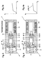
- Fig. 1
- einen Längsschnitt durch ein Ventil mit den der Erfindung zugrunde liegenden Merkmalen in einer ersten Druckregelstellung, in welcher der Erreger- strom dem maximalen elektrischen Ansteuerstrom der Ventilspule entspricht, wodurch der gewünschte Fluidstrom unter hohem Fluiddruck das Ventil durchströmt,
- Figur 2
- das Ventil nach
Figur 1 in einer zweiten Druckre- gelstellung, in welcher der Erregerstrom dem mini- malen elektrischen Ansteuerstrom entspricht, wo- durch der Fluidstrom unter geringem Fluiddruck das Ventil durchströmt, - Figur 3
- das Ventil nach
Figur 1 in einer ersten Fail-Safe- Stellung, in welcher das Ventil elektrisch nicht angesteuert bzw. nicht ansteuerbar ist (Erreger- strom I=0), wobei zur Druckregelung eine Blenden- öffnung aufweisender (zweiter) Ventilöffnungsquer- schnitt freigegeben ist, - Figur 4
- das Ventil nach
Figur 1 in einer zweiten Fail- Safe-Stellung, in welcher das Ventil elektrisch nicht angesteuert bzw. nicht ansteuerbar ist (Er- regerstrom I=0), wobei bis zur Druckbegrenzung auf ein gewünschtes, fest eingestelltes Druckniveau erste, zweite und dritte Ventilöffnungsquerschnit- te freigegeben sind. - Exemplarisch für alle Abbildungen soll anhand der
Figur 1 zunächst der prinzipielle Aufbau des Ventils beschrieben werden. - Es zeigt die
Fig. 1 im Längsschnitt ein elektrisch betätigbares Ventil, das vorzugsweise zur Regelung eines Stossdämpfers in einem Kraftfahrzeug verwendet wird. Das Ventil besteht aus einem elektrischen Stellantrieb 1, einem vom Stellantrieb 1 direkt betätigbaren ersten Ventilkörper 2, der mit einer Steuerkante 3 im Ventilgehäuse 4 zusammenwirkt. Durch das Zusammenwirken des ersten Ventilkörpers 2 mit der Steuerkante 3 ergibt sich mittels des Stellantriebs 1 ein variabel einstellbarer erster Ventilöffnungsquerschnitt A1, durch den ein geregelter Fluidstrom (sog. Primärstrom) in Richtung des im Bereich des Ventilkörpers 2 gelegenen Ventilauslasskanals 16 gelangt. - Ferner ist vor dem ersten Ventilöffnungsquerschnitt A1 ein zweiter Ventilöffnungsquerschnitt A2 zwischen dem kegelförmig erweiterten Innenabschnitt des Ventilgehäuses 4 und einem ringscheibenförmigen zweiten Ventilkörper 6 vorgesehen, der vom Stellantrieb 1 über einen am ersten Ventilkörper 2 angebrachten stößelförmigen Fortsatz 7 zu betätigen ist, dessen Außendurchmesser dem Außendurchmesser des ersten Ventilkörpers 2 entspricht. Der veränderbare zweite Ventilöffnungsquerschnitt A2 befindet sich somit stromaufwärts zum ersten Ventilöffnungsquerschnitt A1 in einer Reihenschaltung zum ersten Ventilöffnungsquerschnitt A1, wobei beide Ventilöffnungsquerschnitte A1, A2 mittels des ersten Ventilkörpers 2 reziprok proportional zueinander zu öffnen und zu verschließen sind.
- Weiterhin ist im zweiten Ventilkörper 6 ein von der Stirnfläche des Fortsatzes 7 normalerweise verschlossener dritter Ventilquerschnitt A3 vorgesehen. Zum Verschluss des zweiten Ventilöffnungsquerschnitts A2 ist der zweite Ventilkörper 6 als ringscheibenförmiger Sitzventilkörper ausgeführt, der an einer Gehäusestufe 14 (Kegelstufe des Ventilgehäuses 4) anlegbar ist. Ein Ventileinlasskanal 17 mündet stromaufwärts zum zweiten Ventilkörper 6 in das Ventilgehäuse 4 ein.
- Der erste Ventilkörper 2 ist im Bereich des ersten Ventilöffnungsquerschnitts A1 bevorzugt als im Ventilgehäuse 4 geführter Ventilkolben ausgeführt, der im elektrisch stromlosen Zustand des Stellantriebs 1 mittels einer auf den zweiten Ventilkörper 6 einwirkenden Rückstellfeder 5 immer von der Steuerkante 3 abgehoben ist, sodass der erste Ventilöffnungsquerschnitt A1 zumindest teilweise geöffnet ist. Hierdurch besteht gleichzeitig eine hydraulische Verbindung zwischen dem Ventilauslass- und Ventileinlasskanal 16, 17 über die Blendenöffnung 8 am zweiten Ventilkörper 6.
- Die Rückstellfeder 5 ist zwischen dem zweiten Ventilkörper 6 und dem Ventilgehäuse 4 angeordnet, sodass im nicht erregten Zustand des Stellantriebs 1 der zweite Ventilkörper 6 immer an der Gehäusestufe 14 (Kegelstufe des Ventilgehäuses 4) dichtend verharrt und ausschließlich die in vorliegendem Ausführungsbeispiel als Umfangskerbe ausgeführte Blendenöffnung 8 des zweiten Ventilkörpers 6 freigegeben ist, so dass im nicht erregten Zustand des Stellantriebs 1 ein geringfügiger Durchlass im Bereich des dritten Ventilöffnungsquerschnitts A3 vorhanden ist, um die vom Querschnitt der Blendenöffnung 8 abhängig hydraulische Verbindung zwischen dem Ventileinlass- und Auslasskanal 17, 16 zu gewährleisten.
- Ferner befindet sich zwischen dem ersten Ventilkörper 2 und einem zwischen dem Stellantrieb 1 und dem Ventilkörper 2 angeordneten Federanschlag 11 eine Druckfeder 9, die dem Hydraulikdruck im Ventileinlasskanal 17 und der Rückstellfeder 5 nur schwach entgegen wirkt. Zur Aufnahme und Führung der Druckfeder 9 und des scheibenförmigen Federanschlags 11 weist der erste Ventilkörper 2 auf seiner vom Fortsatz 7 abgewandten Stirnseite einen Betätigungsstift 10 auf. Unter der permanenten Wirkung der Druckfeder 9 stützt sich der Federanschlag 11 entweder an der Innenwand des Ventilgehäuses 4 oder an einer Anschlagschulter eines mit dem Betätigungsstifts 10 verbundenen Druckstücks 12 ab. Das Druckstück 12 ist innerhalb des Ventilgehäuses 4 gedichtet und ragt mit seiner vom Federanschlag 11 abgewandten Stirnfläche in einer bevorzugten Ausführungsform in den elektromagnetischen Stellantrieb 1, der aus einem das Druckstück 12 betätigenden Magnetanker 13 besteht.
- Selbstverständlich kann bei Wunsch oder Bedarf der erste Ventilkörper 2 anstelle eines Schieberventils auch als Sitzventil ausgeführt sein. Durch die Ausführung des ersten Ventilkörpers 2 als im Ventilgehäuse 4 geführter Tauchkolben, befindet sich bevorzugt am Außenumfang des Tauchkolbens eine Druckverteilernut 15, über die das Fluid zum Druckausgleich in den Raum des Ventilgehäuses 4 gelangt, in dem sich die Druckfeder 9 befindet. Die Abdichtung dieses Raums in Richtung des Stellantriebs erfolgt im einfachsten Fall durch das metallisch dichtende Druckstück 12, das zwangsläufig auch vom Fluiddruck beaufschlagt ist.
- Nachfolgend soll nunmehr beispielhaft anhand den
Fig. 1-4 die unterschiedlichen Ventilstellungen nebst dem zugehörigen Druckverläufen aufgezeigt werden. - Die
Figur 1 zeigt das Ventil mit den der Erfindung zugrunde liegenden Merkmalen in einer ersten Druckregelstellung, in welcher der Erregerstrom dem maximalen elektrischen Ansteuerstrom der am Ventilgehäuse 4 angebrachten Ventilspule entspricht, wodurch der eingeregelte Fluidstrom unter hohem Fluiddruck das Ventil monodirektional durchströmen kann. Infolge des maximalen Erregerstroms imax verschiebt der Magnetanker 13 nämlich die aus dem Druckstück 12, dem Federanschlag 11, der Druckfeder 9, dem ersten und zweiten Ventilkolben 2, 6 und dem Fortsatz 7 bestehende Baugruppe entgegen der Wirkung der Rückstellfeder 5 nach links, wodurch sich der zweite Ventilkolben 6 von der Gehäusestufe 14 entfernt, während sich der erste Ventilkolben 2 der Steuerkante 3 zur Druckregelung nähert. - Die
Fig. 1a zeigt die Druckregelkennlinie für die inFig. 1 abgebildete Druckregelfunktion. Hierzu ist inFig. 1a auf der Ordinate des Diagramms der Druckanstieg p sowie entlang der Abszisse der Volumenstrom Q aufgetragen, wonach infolge des hohen Erregerstroms imax der gewünschte hohe Volumenstrom Q des Fluids durch einen steilen Druckanstieg p des Hydraulikdrucks charakterisiert ist. - Die
Figur 2 zeigt abweichend vonFigur 1 das Ventil in einer Regelstellung, in welcher der Erregerstrom dem minimalen elektrischen Ansteuerstrom der Ventilspule 12 entspricht. Infolge des minimalen Erregerstroms imin verschiebt der Magnetanker 13 die aus dem Druckstück 12, dem Federanschlag 11, der Druckfeder 9, dem ersten und zweiten Ventilkolben 2 und dem Fortsatz 7 bestehende Baugruppe entgegen der Wirkung der Rückstellfeder 5 nur geringfügig nach links, wodurch sich der zweite Ventilkolben 6 nur geringfügig von der Gehäusestufe 14 entfernt, während sich zur Druckregelung der erste Ventilkolben 2 der Steuerkante 3 um den zurückgelegten Wegbetrag des zweiten Ventilkolbens 6 nähert. In dieser Druckregelstellung kommt somit die im Diagramm nachFig. 2a abgebildete Druckregelkennlinie zustande, woraus ein flacher Druckanstieg mit zunehmendem Volumenstrom Q zu entnehmen ist. - Die
Figur 3 zeigt das Ventil in einer ersten Fail-Safe-Stellung, in welcher das Ventil elektrisch nicht angesteuert bzw. nicht ansteuerbar ist (Erregerstrom i=0) und in welcher der zweite Ventilöffnungsquerschnitt A2 quasi bis auf die Leckage über die Blendenöffnung 8 versperrt ist. Der Magnetanker 13 verharrt hierbei in seiner vom Druckstück 12 entfernten Stellung, wodurch infolge der Wirkung der Rückstellfeder 5 der zweite Ventilkörper 6 an der den Ventilsitz bildende Gehäusestufe 14 anliegt. Da sich auf der von der Rückstellfeder 5 abgewandten Stirnseite des zweiten Ventilkörpers 6 der erste Ventilkörper 2 abstützt, entfernt sich zwangsläufig der erste Ventilkörper 2 von der Steuerkante 3 um das Maß, welches dem Schließweg des zweiten Ventilkörpers 6 entspricht. Folglich gelangt ein geringer Fluidstrom ausschließlich über die Blendenöffnung 8 zum geöffneten ersten Ventilöffnungsquerschnitt A1, woraus der inFig. 3a ersichtliche, für die Blendenwirkung charakteristische Kennlinienverlauf resultiert. - Die
Figur 4 zeigt ausgehend von der Darstellung nachFigur 3 das Ventil in einer sogenannten zweiten Fail-Safe-Stellung, die sich von der inFig.3 gezeigten ersten Fail-Safe-Stellung dahingehend unterscheidet, dass der auf die Stirnfläche des Fortsatzes 7 wirkende hydraulische Eingangsdruck den Fortsatz 7 von seiner Sitzfläche am zweiten Ventilkörper 6 abhebt, wodurch zwischen dem Fortsatz 7 und dem zweiten Ventilkörper 6 der dritte Ventilöffnungsquerschnitt A3 freigegeben ist, über den ein sekundärer Fluidstrom parallel zu dem über die Blendenöffnung 8 gedrosselt einströmenden primären Fluidstrom zum ersten Ventilöffnungsquerschnitt A1 und von dort zum Ventilauslasskanal 16 gelangt. Unter Kompression der Druckfeder 9 befindet sich in dieser Ventilstellung das Druckstück 12 kurz vor dem Magnetanker 13. Die Kraft F1 der Druckfeder 9 ist demnach kleiner bemessen als die aus dem Hydraulikdruck p und der Stirnfläche A0 am Druckstück 12 resultierende Hydraulikkraft. - Entsprechend dem Diagramm nach
Fig. 4a stellt sich eine im wesentlichen durch die konstruktive Auslegung des ersten Ventilkolbens 2 und der Druckfeder 9 festgelegte Druckbegrenzungsfunktion ein, in welcher der sekundäre Fluidstrom den zweiten Ventilkolben 6 über dessen offenen dritten Ventilöffnungsquerschnitt A3 parallel zum Primärstrom über die Blendenöffnung 8 passiert. Infolge der hydraulischen Verschiebung des Fortsatzes 7 in Richtung auf die Gehäusestufe 14 gelangt das Fluid über den zweiten Ventilöffnungsquerschnitt A2 gedrosselt zum ersten ungedrosselten Ventilöffnungsquerschnitt A1, dem der Ventilauslasskanal 16 nachgeordnet ist. - Die beiden Ventilkörper 2, 6 sind zweckmäßigerweise derart gestaltet, dass sich die bei der Durchströmung entstehenden Strömungskräfte weitgehend kompensieren.
-
- 1
- Stellantrieb
- 2
- Erster Ventilkörper
- 3
- Steuerkante
- 4
- Ventilgehäuse
- 5
- Rückstellfeder
- 6
- Zweiter Ventilkörper
- 7
- Fortsatz
- 8
- Blendenöffnung
- 9
- Druckfeder
- 10
- Betätigungsstift
- 11
- Federanschlag
- 12
- Druckstück
- 13
- Magnetanker
- 14
- Gehäusestufe
- 15
- Druckverteilernut
- 16
- Ventilauslasskanal
- 17
- Ventileinlasskanal
- A1
- Erster Ventilöffnungsquerschnitt
- A2
- Zweiter Ventilöffnungsquerschnitt
- A3
- Dritter Ventilöffnungsquerschnitt
Claims (9)
- Elektrisch ansteuerbares Ventil, mit einem Stellantrieb (1), einem vom Stellantrieb (1) betätigbaren ersten Ventilkörper (2), der mit einem Ventilsitz im Ventilgehäuse (4) zusammenwirkt, um einen ersten Ventilöffnungsquerschnitt (A1) variabel einstellen zu können, sowie mit einem Ventileinlass- und Ventilauslasskanal (17, 16), dadurch gekennzeichnet, dass im Ventilgehäuse (4) ein vom ersten Ventilkörper (2) betätigbarer zweiter Ventilkörper (6) angeordnet ist, um einen in Reihe zum ersten Ventilöffnungsquerschnitt (A1) angeordneten zweiten Ventilöffnungsquerschnitt (A2) variabel einstellen zu können, dass beide Ventilöffnungsquerschnitte (A1, A2) mittels des ersten Ventilkörpers (2) reziprok proportional zueinander zu öffnen und zu verschließen sind und in dem Fluidströmungsweg vom Ventileinlasskanal (17) zum Ventilauslasskanal (18) angeordnet sind, wobei zur Umgehung des zweiten Ventilöffnungsquerschnitts (A2) und zur Begrenzung des hydraulischen Drucks auf einen mechanisch voreingestellten Wert ein mittels des ersten Ventilkörpers (2) freigebbarer dritter Ventiltiffnungsquerschnitt (A3) in Reihenanordnung zum ersten Ventilöffnungsquerschnitt (A1) vorgesehen ist.
- Ventil nach Anspruch 1, dadurch gekennzeichnet, dass der dritte Ventilöffnungsquerschnitt (A3) zwischen dem zweiten Ventilkörper (6) und einem am ersten Ventilkörper (2) stößelförmig ausgebildeten Fortsatz (7) angeordnet ist, wobei der dritte Ventilöffnungsquerschnitt (A3) außerhalb der Druckbegrenzungsfunktion durch das Anlegen des Fortsatzes (7) am Ventilkörper (6) verschlossen ist.
- Ventil nach Anspruch 1 oder 2, dadurch gekennzeichnet, dass der zweite Ventilkörper (6) in seiner Ruhestellung, in welcher der zweite Ventilöffnungsquerschnitt (A2) verschlossen ist, vorzugsweise unter der Wirkung einer Rückstellfeder (5) an einer Gehäusestufe (14) im Ventilgehäuse (4) verharrt.
- Ventil nach Anspruch 3, dadurch gekennzeichnet, dass der zweite Ventilöffnungsquerschnitt (A2) als ein vom Hub des zweiten Ventilkörpers (6) abhängiger variabler Ringquerschnitt ausgeführt ist, der zwischen der Gehäusestufe (14) und dem ringscheibenförmigen zweiten Ventilkörper (6) angeordnet ist.
- Ventil nach einem der vorangegangenen Ansprüche, dadurch gekennzeichnet, dass mittels einer Reihenschaltung des ersten mit dem zweiten Ventilkörpers (2, 6) der zweite Ventilöffnungsquerschnitt (A2) reziprok proportional zum ersten Ventilöffnungsquerschnitt (A1) variabel zu öffnen oder zu verschließen ist.
- Ventil nach einem der vorangegangenen Ansprüche, dadurch gekennzeichnet, dass der zweite Ventilkörper (6) mit einer Blendenöffnung (8) versehen ist, die vorzugsweise im Bereich des zweiten Ventilöffnungsquerschnitts (A2) angeordnet ist.
- Ventil nach einem der vorangegangenen Ansprüche, dadurch gekennzeichnet, dass der erste Ventilkörper (2) als im Ventilgehäuse (4) geführter Ventilkolben ausgeführt ist, an dessen vom zweiten Ventilkörper (6) abgewandten Stirnfläche ein Betätigungsstift (10) mit einem kolbenförmigen Druckstück (12) angebracht ist, das in Richtung auf den Stellantrieb (1) flüssigkeitsdicht aus dem Ventilgehäuse (4) hervorsteht.
- Ventil nach Anspruch 7, dadurch gekennzeichnet, dass zur Grundpositionierung des ersten Ventilkörpers (2) im Ventilgehäuse (4) zwischen dem Druckstück (12) und dem ersten Ventilkörper (2) eine Druckfeder (9) angeordnet ist, die sich an einem Federanschlag (11) abstützt, der zur Ausführung der mechanisch voreingestellten Druckbegrenzungsfunktion zwischen dem Druckstück (12) und dem ersten Ventilkörper (2) relativ verschiebbar auf dem Betätigungsstift (10) angeordnet ist.
- Ventil nach Anspruch 8, dadurch gekennzeichnet, dass die Druckfeder (9) eine gegenüber der Rückstellfeder (5) geringere Federsteifigkeit aufweist.
Applications Claiming Priority (3)
| Application Number | Priority Date | Filing Date | Title |
|---|---|---|---|
| DE102004027785 | 2004-06-08 | ||
| DE200510014101 DE102005014101A1 (de) | 2004-06-08 | 2005-03-29 | Elektrisch ansteuerbares Ventil |
| PCT/EP2005/052516 WO2005121918A1 (de) | 2004-06-08 | 2005-06-02 | Elektrisch ansteuerbares ventil |
Publications (2)
| Publication Number | Publication Date |
|---|---|
| EP1759256A1 EP1759256A1 (de) | 2007-03-07 |
| EP1759256B1 true EP1759256B1 (de) | 2008-12-17 |
Family
ID=34969787
Family Applications (1)
| Application Number | Title | Priority Date | Filing Date |
|---|---|---|---|
| EP20050752826 Not-in-force EP1759256B1 (de) | 2004-06-08 | 2005-06-02 | Elektrisch ansteuerbares ventil |
Country Status (5)
| Country | Link |
|---|---|
| US (1) | US7798173B2 (de) |
| EP (1) | EP1759256B1 (de) |
| JP (1) | JP2008501917A (de) |
| DE (2) | DE102005014101A1 (de) |
| WO (1) | WO2005121918A1 (de) |
Cited By (2)
| Publication number | Priority date | Publication date | Assignee | Title |
|---|---|---|---|---|
| DE102012011062A1 (de) * | 2012-06-04 | 2013-12-05 | Liebherr-France Sas | Hydrauliksystem und Druckbegrenzungsventil |
| CN103502680A (zh) * | 2011-02-25 | 2014-01-08 | 奥林斯赛车公司 | 阀装置 |
Families Citing this family (10)
| Publication number | Priority date | Publication date | Assignee | Title |
|---|---|---|---|---|
| JP4630760B2 (ja) * | 2004-11-30 | 2011-02-09 | カヤバ工業株式会社 | バルブおよび緩衝器 |
| DE102009019552A1 (de) | 2009-04-30 | 2010-11-11 | Hydac Fluidtechnik Gmbh | Proportional-Drosselventil |
| DE102013201864A1 (de) * | 2013-02-05 | 2014-08-07 | Robert Bosch Gmbh | Bremsventil und hydrostatisches Antriebssystem hiermit |
| US8991840B2 (en) * | 2013-03-14 | 2015-03-31 | Oshkosh Defense, Llc | Load dependent damper for a vehicle suspension system |
| CN104633137B (zh) * | 2015-03-02 | 2017-03-15 | 济南天易迅达电气科技有限公司 | 改善密封性的气体单层开关阀 |
| CN106151650A (zh) * | 2016-08-30 | 2016-11-23 | 吉林光洋自动化液压系统有限公司 | 一种两位三通电磁换向零泄漏阀 |
| DE102019105707B3 (de) * | 2019-01-09 | 2020-06-04 | Kendrion (Villingen) Gmbh | Druckregelventil und Vorrichtung mit einem derartigen Druckregelventil zum Steuern oder Regeln eines Drucks eines Druckfluids in einem Pilotdruckraum |
| DE102019105708B4 (de) * | 2019-03-06 | 2022-05-05 | Kendrion (Villingen) Gmbh | Druckregelventil und Vorrichtung mit einem derartigen Druckregelventil zum Steuern oder Regeln eines Drucks eines Druckfluids in einem Pilotdruckraum |
| DE102019106494B4 (de) * | 2019-03-14 | 2022-05-05 | Kendrion (Villingen) Gmbh | Druckregelventil und Vorrichtung mit einem derartigen Druckregelventil zum Steuern oder Regeln eines Drucks eines Druckfluids in einem Pilotdruckraum |
| HUP1900114A1 (hu) * | 2019-04-05 | 2020-10-28 | Kerox Ipari Es Kereskedelmi Kft | Vezérelt dugattyús szelep |
Family Cites Families (18)
| Publication number | Priority date | Publication date | Assignee | Title |
|---|---|---|---|---|
| US628671A (en) * | 1899-07-11 | High-preqsure-valve | ||
| US702383A (en) * | 1901-08-07 | 1902-06-10 | Frank Tyson | Stop-valve. |
| US1161095A (en) * | 1910-09-28 | 1915-11-23 | George Westinghouse | Internal-combustion engine. |
| US1020535A (en) * | 1911-05-26 | 1912-03-19 | Lupu William Brenner | Sectional valve for gas-engines. |
| US1397251A (en) * | 1920-12-27 | 1921-11-15 | Haines Products Company | Dripless faucet |
| US3582571A (en) | 1968-10-16 | 1971-06-01 | Ibm | Multigap magnetic head having gaps disposed at an angle to each other |
| DE3038797A1 (de) * | 1980-10-14 | 1982-05-27 | Herion-Werke Kg, 7012 Fellbach | Druckregelventil |
| US4437830A (en) * | 1982-07-19 | 1984-03-20 | Combustion Engineering, Inc. | Burner and pilot valve safety control system |
| DE3412351A1 (de) * | 1984-04-03 | 1985-10-10 | Mannesmann Rexroth GmbH, 8770 Lohr | Magnetventil zum regeln des bremsdruckes in einem bremszylinder eines kraftfahrzeuges |
| DE4231239A1 (de) * | 1992-09-18 | 1994-03-24 | Bosch Gmbh Robert | Vorrichtung zur Regelung der Leerlaufdrehzahl einer Brennkraftmaschine |
| JPH06137228A (ja) * | 1992-10-23 | 1994-05-17 | Nippondenso Co Ltd | 三方電磁弁 |
| US5609400A (en) * | 1993-09-27 | 1997-03-11 | Sumitomo Electric Industries, Ltd. | Three position solenoid controlled valve |
| DE4426152C2 (de) | 1994-07-23 | 1999-01-07 | Zahnradfabrik Friedrichshafen | Elektromagnetisches Druckregelventil |
| DE4427905A1 (de) | 1994-08-06 | 1996-02-08 | Teves Gmbh Alfred | Ventilvorrichtung, insbesondere für hydraulische Bremsanlagen mit Blockier- und/oder Antriebsschlupfregelung |
| DE19711289A1 (de) | 1997-03-18 | 1998-09-24 | Itt Mfg Enterprises Inc | Ventil, insbesondere für eine hydraulische Bremsanlage |
| JP4267079B2 (ja) | 1997-04-18 | 2009-05-27 | ツェットエフ、フリードリッヒスハーフェン、アクチエンゲゼルシャフト | 圧力制御弁 |
| US6231029B1 (en) * | 1998-11-13 | 2001-05-15 | Mando Machinery Corporation | Solenoid valve for anti-lock brake system |
| JP3353824B2 (ja) * | 1999-04-22 | 2002-12-03 | 日本電気株式会社 | ネットワーク同期システム及びネットワーク同期方法 |
-
2005
- 2005-03-29 DE DE200510014101 patent/DE102005014101A1/de not_active Withdrawn
- 2005-06-02 US US11/629,120 patent/US7798173B2/en not_active Expired - Fee Related
- 2005-06-02 EP EP20050752826 patent/EP1759256B1/de not_active Not-in-force
- 2005-06-02 DE DE200550006280 patent/DE502005006280D1/de active Active
- 2005-06-02 WO PCT/EP2005/052516 patent/WO2005121918A1/de active Application Filing
- 2005-06-02 JP JP2007526414A patent/JP2008501917A/ja active Pending
Cited By (3)
| Publication number | Priority date | Publication date | Assignee | Title |
|---|---|---|---|---|
| CN103502680A (zh) * | 2011-02-25 | 2014-01-08 | 奥林斯赛车公司 | 阀装置 |
| CN103502680B (zh) * | 2011-02-25 | 2016-03-16 | 奥林斯赛车公司 | 阀装置 |
| DE102012011062A1 (de) * | 2012-06-04 | 2013-12-05 | Liebherr-France Sas | Hydrauliksystem und Druckbegrenzungsventil |
Also Published As
| Publication number | Publication date |
|---|---|
| EP1759256A1 (de) | 2007-03-07 |
| DE502005006280D1 (de) | 2009-01-29 |
| DE102005014101A1 (de) | 2005-12-29 |
| US20080283135A1 (en) | 2008-11-20 |
| WO2005121918A1 (de) | 2005-12-22 |
| JP2008501917A (ja) | 2008-01-24 |
| US7798173B2 (en) | 2010-09-21 |
Similar Documents
| Publication | Publication Date | Title |
|---|---|---|
| EP1759256B1 (de) | Elektrisch ansteuerbares ventil | |
| EP0790909B1 (de) | Druckregelventil | |
| EP1004066B2 (de) | Elektromagnetisches druckregelventil | |
| EP0773877B1 (de) | Ventilvorrichtung, insbesondere für hydraulische bremsanlagen mit blockier- und/oder antriebsschlupfregelung, und verfahren zur einstellung einer ventilvorrichtung | |
| DE19826076C1 (de) | Doppelsicherheitsventil | |
| EP1301837A2 (de) | Proportional-druckregelventil | |
| EP0976013B1 (de) | Druckregelventil | |
| EP1771675B1 (de) | Elektrisch ansteuerbares ventil | |
| DE102008039959A1 (de) | Druckregelventil | |
| DE29617922U1 (de) | Magnetbetätigtes Ablaßventil eines elektrohydraulischen Hubmoduls | |
| DE102005023547A1 (de) | Elektrisch ansteuerbares Ventil | |
| DE102013213712A1 (de) | Elektromagnetischer Aktor sowie Fluidventil mit einem solchen Aktor | |
| DE102013213713A1 (de) | Fluidventil | |
| DE102007010213B3 (de) | Elektromagnetisches Regelventil und Verfahren zu dessen Steuerung | |
| EP1232081B1 (de) | Elektromagnetventil | |
| DE102007005465A1 (de) | Elektrisch ansteuerbares Ventil | |
| DE102004057873B4 (de) | Sitzventil | |
| EP3844374A1 (de) | Ventil | |
| EP0041247A2 (de) | Vorgesteuerte Vorrichtung zur lastunabhängigen Volumenstromregelung | |
| DE102005038215A1 (de) | Mehrwegventil | |
| DE3822830A1 (de) | Eigenmediumbetaetigtes, durch ein bistabiles magnetventil servogesteuertes ventil fuer fluessige medien | |
| DE10007349A1 (de) | Stetigventil | |
| DE102006043849A1 (de) | Ventilbaugruppe | |
| DE102006053136A1 (de) | Ventilbaugruppe | |
| WO2004092591A1 (de) | Stetig verstellbares wegeventil |
Legal Events
| Date | Code | Title | Description |
|---|---|---|---|
| PUAI | Public reference made under article 153(3) epc to a published international application that has entered the european phase |
Free format text: ORIGINAL CODE: 0009012 |
|
| AK | Designated contracting states |
Kind code of ref document: A1 Designated state(s): DE FR |
|
| 17P | Request for examination filed |
Effective date: 20070108 |
|
| 17Q | First examination report despatched |
Effective date: 20070709 |
|
| DAX | Request for extension of the european patent (deleted) | ||
| RBV | Designated contracting states (corrected) |
Designated state(s): DE FR |
|
| GRAP | Despatch of communication of intention to grant a patent |
Free format text: ORIGINAL CODE: EPIDOSNIGR1 |
|
| GRAS | Grant fee paid |
Free format text: ORIGINAL CODE: EPIDOSNIGR3 |
|
| GRAS | Grant fee paid |
Free format text: ORIGINAL CODE: EPIDOSNIGR3 |
|
| GRAA | (expected) grant |
Free format text: ORIGINAL CODE: 0009210 |
|
| AK | Designated contracting states |
Kind code of ref document: B1 Designated state(s): DE FR |
|
| REF | Corresponds to: |
Ref document number: 502005006280 Country of ref document: DE Date of ref document: 20090129 Kind code of ref document: P |
|
| PLBE | No opposition filed within time limit |
Free format text: ORIGINAL CODE: 0009261 |
|
| STAA | Information on the status of an ep patent application or granted ep patent |
Free format text: STATUS: NO OPPOSITION FILED WITHIN TIME LIMIT |
|
| 26N | No opposition filed |
Effective date: 20090918 |
|
| PGFP | Annual fee paid to national office [announced via postgrant information from national office to epo] |
Ref country code: FR Payment date: 20110711 Year of fee payment: 7 |
|
| PGFP | Annual fee paid to national office [announced via postgrant information from national office to epo] |
Ref country code: DE Payment date: 20110630 Year of fee payment: 7 |
|
| REG | Reference to a national code |
Ref country code: DE Ref legal event code: R231 Ref document number: 502005006280 Country of ref document: DE |
|
| PG25 | Lapsed in a contracting state [announced via postgrant information from national office to epo] |
Ref country code: DE Free format text: LAPSE BECAUSE OF THE APPLICANT RENOUNCES Effective date: 20120505 |
|
| REG | Reference to a national code |
Ref country code: FR Ref legal event code: ST Effective date: 20130228 |
|
| PG25 | Lapsed in a contracting state [announced via postgrant information from national office to epo] |
Ref country code: FR Free format text: LAPSE BECAUSE OF NON-PAYMENT OF DUE FEES Effective date: 20120702 |