EP1757221A1 - Endoscope électronique - Google Patents
Endoscope électronique Download PDFInfo
- Publication number
- EP1757221A1 EP1757221A1 EP05739184A EP05739184A EP1757221A1 EP 1757221 A1 EP1757221 A1 EP 1757221A1 EP 05739184 A EP05739184 A EP 05739184A EP 05739184 A EP05739184 A EP 05739184A EP 1757221 A1 EP1757221 A1 EP 1757221A1
- Authority
- EP
- European Patent Office
- Prior art keywords
- image
- distal end
- image capturing
- objective optical
- signal
- Prior art date
- Legal status (The legal status is an assumption and is not a legal conclusion. Google has not performed a legal analysis and makes no representation as to the accuracy of the status listed.)
- Pending
Links
Images


Classifications
-
- A—HUMAN NECESSITIES
- A61—MEDICAL OR VETERINARY SCIENCE; HYGIENE
- A61B—DIAGNOSIS; SURGERY; IDENTIFICATION
- A61B1/00—Instruments for performing medical examinations of the interior of cavities or tubes of the body by visual or photographical inspection, e.g. endoscopes; Illuminating arrangements therefor
- A61B1/04—Instruments for performing medical examinations of the interior of cavities or tubes of the body by visual or photographical inspection, e.g. endoscopes; Illuminating arrangements therefor combined with photographic or television appliances
- A61B1/055—Instruments for performing medical examinations of the interior of cavities or tubes of the body by visual or photographical inspection, e.g. endoscopes; Illuminating arrangements therefor combined with photographic or television appliances having rod-lens arrangements
-
- A—HUMAN NECESSITIES
- A61—MEDICAL OR VETERINARY SCIENCE; HYGIENE
- A61B—DIAGNOSIS; SURGERY; IDENTIFICATION
- A61B1/00—Instruments for performing medical examinations of the interior of cavities or tubes of the body by visual or photographical inspection, e.g. endoscopes; Illuminating arrangements therefor
- A61B1/04—Instruments for performing medical examinations of the interior of cavities or tubes of the body by visual or photographical inspection, e.g. endoscopes; Illuminating arrangements therefor combined with photographic or television appliances
-
- A—HUMAN NECESSITIES
- A61—MEDICAL OR VETERINARY SCIENCE; HYGIENE
- A61B—DIAGNOSIS; SURGERY; IDENTIFICATION
- A61B1/00—Instruments for performing medical examinations of the interior of cavities or tubes of the body by visual or photographical inspection, e.g. endoscopes; Illuminating arrangements therefor
- A61B1/00002—Operational features of endoscopes
- A61B1/00004—Operational features of endoscopes characterised by electronic signal processing
- A61B1/00009—Operational features of endoscopes characterised by electronic signal processing of image signals during a use of endoscope
-
- A—HUMAN NECESSITIES
- A61—MEDICAL OR VETERINARY SCIENCE; HYGIENE
- A61B—DIAGNOSIS; SURGERY; IDENTIFICATION
- A61B1/00—Instruments for performing medical examinations of the interior of cavities or tubes of the body by visual or photographical inspection, e.g. endoscopes; Illuminating arrangements therefor
- A61B1/00064—Constructional details of the endoscope body
- A61B1/00071—Insertion part of the endoscope body
- A61B1/0008—Insertion part of the endoscope body characterised by distal tip features
- A61B1/00096—Optical elements
-
- A—HUMAN NECESSITIES
- A61—MEDICAL OR VETERINARY SCIENCE; HYGIENE
- A61B—DIAGNOSIS; SURGERY; IDENTIFICATION
- A61B1/00—Instruments for performing medical examinations of the interior of cavities or tubes of the body by visual or photographical inspection, e.g. endoscopes; Illuminating arrangements therefor
- A61B1/00163—Optical arrangements
- A61B1/00188—Optical arrangements with focusing or zooming features
-
- A—HUMAN NECESSITIES
- A61—MEDICAL OR VETERINARY SCIENCE; HYGIENE
- A61B—DIAGNOSIS; SURGERY; IDENTIFICATION
- A61B1/00—Instruments for performing medical examinations of the interior of cavities or tubes of the body by visual or photographical inspection, e.g. endoscopes; Illuminating arrangements therefor
- A61B1/012—Instruments for performing medical examinations of the interior of cavities or tubes of the body by visual or photographical inspection, e.g. endoscopes; Illuminating arrangements therefor characterised by internal passages or accessories therefor
- A61B1/018—Instruments for performing medical examinations of the interior of cavities or tubes of the body by visual or photographical inspection, e.g. endoscopes; Illuminating arrangements therefor characterised by internal passages or accessories therefor for receiving instruments
Definitions
- the present invention relates to an electronic endoscope which comprises a solid image capturing element and which can be used with various treatment tools.
- endoscopes enable, for example, the interior of a living organism, which is not directly visible, to be observed and have been widely used for diagnosis and treatment mainly in medical fields. Further, electronic endoscopes have been prevailing which convert a subject image into an electric signal using a solid image capturing element such as a CCD so that the image can be observed via a monitor. In recent years, the following have also been spreading: electronic endoscopes that employ a zoom optical system in order to closely observe a subject and high-resolution endoscopes that use a multi-pixel solid image capturing element.
- the former electronic endoscope employing a zoom optical system cannot adopt a complicated configuration owing to a limitation on the increased size of configuration of a distal end. Accordingly, resizing zoom optical systems are commonly used which move one lens group to vary the view angle.
- Such a resizing zoom optical system as shown in Japanese Patent Laid-Open No. 2000-330019 is composed of a first lens group 10 having a negative refractive power, a brightness aperture S, a second lens group 20 having a positive refractive power, and a third lens group 30 having a negative refractive power; these groups are arranged in this order from an object as shown in Fig. 1 of this publication.
- This system is characterized in that for resizing, the second lens group 20 moves to two different points on an optical axis which do not vary an inter-object-image distance with the first lens group 10 and third lens group 30 immobilized.
- G denotes filters.
- This configuration is effective in providing a small, high-performance objective resizing optical system which does not vary the inter-object-image distance and which is suitable for a two-focus type endoscope.
- the configuration is also effective in enabling the subject to be closely observed using a zoom optical system.
- the latter high-resolution endoscope using a multi-pixel solid image capturing element uses a solid image capturing element having more pixels than in the prior art to enable an image of a subject to be captured at a higher resolution. This is effective in enabling the subject to be closely observed.
- the endoscope using a resizing zoom optical system as shown in Japanese Patent Laid-Open No. 2000-330019 moves lenses in an image capturing optical system to vary the angle of view and thus the scale. Thus, to increase the scale, this endoscope needs to reduce the angle of view.
- the angle of view of the image capturing system and the distance between the adjacent image capturing optical system and the treatment tool determine whether or not an image capturing optical system including a solid image capturing element captures an image of a treatment tool projecting from a channel distal end opening.
- an image of the projecting treatment tool is captured earlier (with a less amount of projection) with decreasing distance between the adjacent image capturing optical system and the treatment tool or increasing angle of view of the image capturing optical system.
- an endoscope using a single-focus optical system comprises a multi-pixel solid image capturing element in order to enable high-definition observations
- the depth of field of the optical system generally decreases with increasing number of pixels. Accordingly, when to allow the subject to be closely observed, the optical system is adjusted so that a high resolution is obtained when the endoscope lies closest to the subject, the depth of field for a far point is insufficient, making it difficult to provide the endoscope with an appropriate depth of field in a practical sense.
- Fno For example, for an image capturing optical system using a solid image capturing element based on a mosaic filter scheme with at least one million pixels, Fno needs to be increased in order to increase the depth of field. However, too large an Fno degrades the contrast of an image owing to diffraction of light. Consequently, it is difficult for the single-focus optical system to achieve both high resolution and practical depth of field when the endoscope lies closest to the subject.
- An object of the present invention is to provide an electronic endoscope which can be used with a single-focus objective optical system to offer a practical depth of field and to enable treatment to be executed with a treatment tool while closely observing the subject.
- Another object of the present invention is to provide an electronic endoscope that can be used with a focal-point-varying objective optical system to enable treatment to be executed with a treatment tool while closely observing the subject on a near point side.
- the present invention provides an electronic endoscope using a single-focus objective optical system comprising:
- the present invention provides an electronic endoscope using a focal-position-varying objective optical system comprising:
- Embodiment 1 of the present invention will be described with reference to Figs. 1 to 6.
- an electronic endoscope system 1 is composed of an electronic endoscope 2 according to Embodiment 1, a light source device 3 that serves as a light source to supply illumination light for the electronic endoscope 2, an image processing device (signal processing device) 4 incorporated in the electronic endoscope to process signals for image capturing means, and a monitor 5 which supports a high vision TV (hereinafter simply referred to as HDTV) to which standard video signals output by the image processing device 4 are input, to display endoscope images.
- HDTV high vision TV
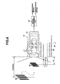
- the electronic endoscope 2 in the present embodiment has an insertion unit 7 that is inserted into a subject, a manipulation unit 8 provided at a trailing end of the insertion unit 7 that is operated by a user, and a cable unit 9 extended from the manipulation unit 8.
- the insertion unit 7 has a rigid distal end portion 11 at its tip which is provided with an image capturing unit and the like described below.
- a light guide 14 is inserted through the insertion unit 7 to transmit illumination light.
- a trailing end of the light guide 14 leads through a cable unit 9 to a light guide connector 15 provided at an end of the cable unit 9. Connection of the light guide connector 15 to the light source device 3 allows the light source device 3 to supply illumination light to a trailing end surface of the light guide 14.
- Illumination light supplied by the light source device 3 is transmitted via the light guide 14.
- the light is emitted forward from a distal end surface fixed to the distal end portion 11, through illumination lenses 16a and 16b (see Fig. 3) attached to an illumination window opposite the distal end surface.
- the light thus illuminates a subject such as a diseased site in the celom or the like.
- the distal end portion 11 is provided with an observation window (or an image capturing window) adjacent to the illumination window.
- An image capturing unit 19 is placed in the image capturing window; the image capturing unit comprises an objective lens system (or objective optical system) 17 that forms an optical image of the illuminated subject, and for example, a charge coupled device (hereinafter simply referred to as a CCD) 18 which serves as an image capturing element and which has a light receiving surface (or photoelectrical converting surface) placed at the position where the objective lens system 17 forms an image.
- a CCD charge coupled device
- One end of the signal cable 21 is connected to the image capturing unit 19.
- the signal cable 21 inserted through the insertion unit 7 is further inserted through the cable unit 9.
- the other end of the signal cable 21 is connected to a signal connector 22 located at a trailing end of the cable unit 9.
- Connection of the signal connector 22 to the image processing device 4 allows the CCD 18 to be driven in accordance with a CCD driving signal from a CCD driving unit 23 of the image processing device 4.
- the CCD 18 then outputs a photoelectrically converted image signal (image capturing signal).
- the image capturing signal is processed in the image processing device 4.
- An endoscope image is displayed on the monitor 5.
- a channel 25 is formed in the insertion unit 7 so that various treatment tools can be inserted through the channel 25.
- the channel 25 comprises a channel distal end opening (also referred to as a distal end opening or forceps port) 26 formed in the distal end portion 11, a treatment tool insertion port 27 located near a front end of the manipulation unit 8, and a channel tube 25a that connects the distal end opening 26 and the treatment tool insertion port 27 together.
- Insertion of a treatment tool 28 through the treatment tool insertion port 27 allows a distal end of the treatment tool 28 to be projected from the distal end opening 26.
- the diseased tissue can be collected or excised using the distal end of the treatment tool 28.
- the present embodiment allows a subject such as a diseased tissue which is to be examined or treated and the distal end of the treatment tool 28 projected from the distal end opening 26 to come into the view of the image capturing unit 19 with a reduced amount of projection. This enables the distal end of the projected treatment tool 28 to be displayed on a display surface of the monitor 5. An operator can smoothly execute treatment or the like.
- the CCD 18 is based on a mosaic color filter scheme and comprises a complementary-color mosaic color filter.
- the CCD 18 has a pixel pitch of 2.5 ⁇ m and uses 810 thousand pixels that are effective for monitor display.
- the CCD 18 also has a maximum image height of 1.3 mm on the CCD light receiving surface.
- the image capturing unit 19 uses a single-focus objective lens system 17 having a maximum angle of view of 138°.
- the objective lens system 17 is set to have an Fno (F number) of 10.0 so as not to exceed a light diffraction limit. Further, the focus is adjusted so as to obtain the maximum resolution at an object distance of 4.2 mm.
- Lens data on the objective lens system 17 used in the present embodiment is shown below.
- Fl denotes the focal distance of the objective lens system 17.
- Ra denotes the radius of curvature of a lens.
- Da denotes a surface interval.
- Ne denotes a refractive index for a mercury e line (wavelength: 546.07 nm).
- Vd denotes an Abbe number.
- Fl 1.33785 mm Surface No.
- a plurality of lenses constituting the objective lens system 17 are fixedly held using a lens frame 31 and spacers 32a and 32b so as to be centered and to maintain the proper surface spacing.
- the CCD 18 is composed of a CCD chip 18a, a CCD substrate 18b, a CCD driving part 18c, and sealing glass 18d.
- the CCD substrate 18b is electrically connected to the CCD chip 18a by wire bonding or the like and mechanically fixed with an adhesive or the like.
- a coupling capacitor and the CCD driving part 18c such as a current amplifying transistor are arranged on and soldered to the CCD substrate 18b.
- the sealing glass 18d is fixedly bonded to the light receiving surface of the CCD chip 18a with an optical adhesive or the like in order to protect the light receiving surface.
- the lens frame 31 is fitted into a CCD frame 33 so as to be movable parallel to the optical axis of the objective lens system 17.
- the CCD 18 is fixedly bonded to the CCD frame 33 so that the optical axis of the objective lens system 17 is perpendicular to the light receiving surface of the CCD 18.
- a land (not shown) is provided on the CCD substrate 18b so that a signal line in the signal cable 21 can be soldered to the land.
- the signal line in the signal cable 21 is soldered to the land.
- a CCD protect frame 34 is placed so as to protect an area from the CCD frame 33 through the CCD 18 to the connection of the signal cable 21 with the CCD substrate 18b.
- the CCD protect frame 34 has a notch portion formed near the back surface of the CCD chip 18a.
- a thermally conductive heat radiation member 35 formed of, for example, an aluminum alloy or a copper alloy is placed so as to be inserted through the notch portion.
- a heat radiation cable 36 comprising a thermally conductive metal as a conductor is mechanically connected to the heat radiation member 35 with solder, an adhesive, or the like.
- a sealing resin is filled into the CCD protect frame 34, and the periphery of CCD 18 is sealed with a thermally contractive tube 37.
- the heat radiation cable 36 is soldered to a member with a large thermal capacity, for example, the distal end portion 11 of the insertion unit 7.
- the signal cable 21 is formed by twisting a plurality of coaxial wires and a plurality of single wires together, winding a fluorine resin tape around the wires, further winding a copper wire around the tape as a bundle shield, further winding a fluorine resin tape around the wire, and covering the tape with a Teflon (registered trade mark) based sheath.
- the image capturing unit 19 includes the objective lens system 17 having a distal end lens of outer diameter ⁇ 2.8 mm, the air and water supplying nozzle 39 feeds water or gas to the outer surface of the objective lens system 17 to remove contaminants, and the illumination lenses 16a and 16b are used to illuminate the subject with light transmitted (conducted) through the light guide 14 connected to the light source device 3.
- the image capturing unit 19 is attached to the distal end portion 11 so that the up and down direction of a captured image of the subject displayed on the monitor 5 aligns with the up and down direction of the distal end portion 11 of the insertion unit 7 in Fig. 3.
- the channel tube 25a in the present embodiment is made of Teflon (registered trade mark) and has an inner diameter of 2.8 mm.
- the optical axis O of the objective lens system 17 is placed parallel to the distal end opening 26 (to which the distal end of the channel tube 25a is connected).
- the distance D between the center (optical axis O) of the objective lens system 17 and the center axis of the distal end opening 26 is set at 6 mm.
- Double the radius R of the distal end opening 26 is equal to the inner diameter of the channel tube 25a, 2.8 mm.
- the light source device 3 has a lamp 40. Illumination light from the lamp 40 has its light transmission amount adjusted by the opening of the aperture 42, driven by the aperture driving unit 41. The light then enters an incident end surface of the light guide 14 of the light guide connector 15 through a light condensing lens 43. The illumination light is then emitted from the distal end of the light guide 14 to the subject through the illumination lenses 16a and 16b as described above.
- the light guide 14 branches to two portions inside the insertion unit 7.
- the illumination light is thus emitted from the illumination lenses 16a and 1.6b, arranged at the respective positions in the distal end portion 11 as shown in Fig. 3.
- the image processing device 4 has a CDS circuit 44 to which an image signal from the CCD 18 is input.
- the CDS circuit 44 extracts a signal component and an A/D converter 45 converts the signal component into a digital signal.
- the resulting digital image signal from the A/D converter 45 is input to a signal conversion unit 46 that generates a video signal comprising a brightness signal and a chlominance signal.
- a video signal generated by the signal conversion unit 46 is input to an image processing unit 47 that executes various image processes such as ⁇ correction.
- An output signal from the image processing unit 47 is input to a D/A converter 48. The signal is thus converted into a video signal compatible with an analog HDTV scheme, which is then output to the monitor 5.
- a brightness signal from the signal conversion unit 46 is input to an automatic dimming unit 49, which then generates an automatic dimming signal.
- the automatic dimming signal is input to the aperture driving unit 41 of the light source device 3 to automatically adjust the numerical aperture of the aperture 42.
- the automatic dimming unit 49 contains a treatment tool detection unit 49a that detects that a treatment tool has come into the view of the image capturing unit 19 (in other words, an image of the treatment tool is formed on the light receiving surface of the CCD 18), on the basis of, for example, the quantity of light reflected by the treatment tool or its color.
- the automatic dimming unit 49 has a brightness detection unit 49b that detects brightness to be adjusted in an output signal from the treatment tool detection unit 49a and a dimming signal generating unit 49c that generates an automatic dimming signal from an output signal from the brightness detection unit 49b.
- the brightness detection unit 49b detects the peak brightness (light quantity) of vicinity of the area in which an image of the treatment tool is formed and the average brightness (light quantity) of the vicinity.
- the brightness detection unit 49b detects the peak brightness and average brightness of the entire screen.
- the dimming signal generating unit 49c generates an automatic dimming signal that adjusts the illumination light quantity of the light source device 3 so as to obtain a signal with a proper brightness, on the basis of signals for the peak brightness and average brightness from the brightness detection unit 49b.
- the dimming signal generating unit 49b then outputs the automatic dimming signal to the aperture driving unit 41 of the light source device 3.
- the image capturing unit 19 comprising the single-focus objective lens system 17, indicated by the above lens data, and the CCD 18, offers a resolution at which 35- ⁇ m pitch black and white subjects can be distinguished from one another, which is higher than a conventionally achievable resolution at which about 50- ⁇ m pitch black and white subjects to be distinguished from one another (the image capturing system 17 meets the corresponding condition).
- the image capturing unit 19 also offers a resolution required to observe a distant view, which is comparable to that in the prior art.
- the CCD 18 of the image capturing unit 19 executes signal processing to generate a standard video signal for the image signal. If the video signal is displayed on the display surface of the monitor 5, the display image enables 35- ⁇ m pitch black and white subjects to be distinguished from one another.
- the resolution required to observe the distant view side enables 0.5-mm pitch black and white subjects to be distinguished from one another at a distance of, for example, about 50 mm from the image capturing unit 19. This resolution is called a distant view resolution. Further, the resolution required to enable the 35- ⁇ m pitch black and white subjects to be distinguished from one another is called a proximity side close resolution.
- the distal end of the treatment tool 28 comes into the view of the image capturing unit 19 at an object distance at which if the distal end of the treatment tool 28 inserted through the channel 25 is projected from the distal end opening 26, the resolution required to enable 35- ⁇ m pitch black and white subjects to be distinguished from one another is obtained.
- an image of the distal end of the treatment tool 28 projected only by a small amount is formed on the light receiving surface of the CCD 18. This enables the vicinity of distal end of the treatment tool 28 to be closely observed, allowing close treatments to be executed using the treatment tool 28.
- the light guide connector 15 of the electronic endoscope 2 is connected to the light source device 3. Further, the signal connector 22 is connected to the image processing device 4. Furthermore, the cable from the monitor 5 is connected to a picture output end of the image processing device 4 to allow endoscope examinations to be executed.
- a power supply switch (not shown) is turned on to supply illumination light from the light source device 3 to the light guide 14.
- the illumination light is emitted from the illumination lenses 16a and 16b via the light guide 14 so that the subject, which is to be subjected to image capturing by the image capturing unit 19, can be illuminated. Further, under these conditions, an image captured by the CCD 18 of the image capturing unit 19 is displayed on the monitor 5 via the image processing device 4.
- the insertion unit 7 of the electronic endoscope 2 is inserted into the patient's celom so that the subject in the site which is to be examined using the endoscope, such as a diseased site in the celom, can be observed using the distal end portion 11 of the insertion unit 7.
- the objective lens system 17 of the image capturing unit 19, provided in the distal end portion 11, forms an optical image of the subject on the light receiving surface of the CCD 18.
- the image formed on the light receiving surface of the CCD 18 is photoelectrically converted into an image signal.
- the image signal is input to the CDS circuit 44 of the image processing device 4 via the signal cable 21 and signal connector 22.
- the image signal has a waveform containing reset noise or the like in addition to a signal component.
- the CDS circuit 44 extracts the signal component to generate a baseband signal.
- An output signal from the CDS circuit 44 is input to the A/D converter 45, which then converts the image signal, which is an analog signal, into a digital signal.
- the image signal converted into the digital signal is further converted into a video signal by the signal conversion unit 46.
- the present embodiment employs a complementary-color mosaic color filter as the CCD 18. Accordingly, the signal conversion unit 46 converts the image signal into a video signal such as a brightness signal that is the average of pixel signal outputs from adjacent four types of color filters or a color difference signal obtained from the differences among pixel signal outputs of specific colors.
- a video signal such as a brightness signal that is the average of pixel signal outputs from adjacent four types of color filters or a color difference signal obtained from the differences among pixel signal outputs of specific colors.
- This video signal has its contrast, color, display size, and the like adjusted by the image processing unit 47 so as to have suitable values for monitor display.
- the D/A converter 48 converts the video signal into a signal which is compatible with the analog HDTV scheme and which can be displayed on the monitor 5.
- the monitor 5 displays the image of the subject (captured by the CCD 18) corresponding to the input HDTV-compatible video signal, on a monitor screen 5a.
- Fig. 6 is a schematic diagram showing that the insertion unit 7 of the electronic endoscope 2 of the present embodiment is inserted into the celom and that the image capturing unit 19, provided in the distal end portion 11, is used to capture an image of the treatment target site in the celom, while the treatment tool 28 is projected from the distal end opening 26 for treatment.
- the conditions under which treatment can be easily executed include an appropriate resolution at which an image of the distant view can be captured (observed). Further, it is desirable to be able to closely observe the diseased site or the like to be treated and to closely observe the distal end of the treatment tool 28 projected from the distal end opening 26.
- the present embodiment meets these conditions as described below.
- the brightness contrast G is defined as described below.
- the maximum value of brightness of the white subject is defined as Gmax
- the minimum value of brightness of the black subject is defined as Gmin
- the brightness contrast G is thus defined, when the image capturing unit 19 configured as described above captures an image of black and white band subjects arranged at a pitch of 35 ⁇ m, at an object distance of 4.2 mm, at which the best resolution is obtained, the brightness contrast G of the black and white bands formed on the CCD light receiving surface is 14.5%.
- the difference between an image signal output from the pixel at which an image of the white band is formed and an image signal output from the pixel at which an image of the black band is formed is approximately 14.5%.
- the image signal is input to the image processing unit 47 via the CDS circuit 44, A/D converter 45, and signal conversion unit 46.
- the signal is then subjected to, for example, a gamma process suitable for the monitor 5 or a low pass filter process for removing noise.
- the maximum value of a brightness signal obtained from the white subject is defined as Imax
- the minimum value of a brightness signal obtained from the black subject is defined as Imin
- the image of the 35- ⁇ m pitch black and white bands captured by the image capturing unit 19 can be viewed as a black and white band pair on the monitor 5.
- a brightness signal forming a video signal output by, for example, the signal conversion unit 46 as a result of the photoelectric conversion by the CCD 18 has a contrast I of at least 10%. This enables the 35- ⁇ m pitch black and white band pair to be viewed on the monitor 5.
- the image capturing unit 19 is used to capture an image of a subject Sb placed at an object distance of 50 mm and comprising a 0.5-mm pitch black and white band pair, then an image of the black and white bands formed on the CCD light receiving surface has a contrast G of 25%.
- the difference between an image signal output from the pixel at which an image of the white band is formed as a result of a photoelectric conversion and an image signal output from the pixel at which an image of the black band is formed as a result of a photoelectric conversion is about 25%.
- the image processing device 4 thus outputs the image on the monitor 5 so that the black and white bands have a contrast I of at least 10%.
- Fig. 6 shows that a 0.5-mm pitch black and white band pair (stripes) Sb is placed at an object distance d2 of 50 mm. Also in this case, a brightness signal from the signal conversion unit 46 has a black and white contrast I of at least 10%. This enables the black and white band pair to be viewed on the monitor 5.
- a manipulator inserts a treatment tool to be used into the treatment tool insertion port 27, formed in the vicinity of the manipulation unit 8.
- the treatment tool inserted through the treatment tool insertion port 27 passes through the channel 25 in the channel tube 25a in the insertion unit 7.
- the treatment tool 28 is then guided to the distal end portion 11 of the insertion unit 7.
- the distal end of the treatment tool 28 projects from the channel distal end opening 26 in the distal end portion 11.
- the treatment tool 28 starts to come into the view of the image capturing unit 19 when the amount of projection of the distal end portion 11 from the distal end surface is at least 1.38 mm.
- the distal end portion 11 is projected by 2.45 mm, almost the entire distal end of the treatment tool 28 comes into the view of the image capturing unit 19.
- the distal end of the treatment tool 28 is ensured to come into the view of the image capturing unit 19. Consequently, the distal end can be viewed on the monitor 4.
- Fig. 6 also shows that the treatment tool 28 projects from the distal end opening 26 of the channel. After the distal end of the treatment tool 28 comes into the view of the image capturing unit 19, projecting the treatment tool 28 further forward places the distal end at an object distance for the maximum resolution.
- the subject such as a diseased site which is to be treated using the treatment tool 28 to be closely observed.
- the distal end of the treatment tool 28 projecting to the vicinity of the subject can also be closely observed. This facilitates treatment.
- the distant view resolution is provided for the distant view. This makes it possible to determine the status of a wide peripheral area of the site to be treated, allowing treatment to be executed more smoothly.
- an automatic dimming unit 49 uses a brightness detection unit 49b to sense the brightness (specifically, the peak brightness or average brightness) of the entire screen and outputs the brightness to a dimming signal generating unit 49c.
- the dimming signal generating unit 49c outputs a control signal allowing the light source device 3 to increase the light quantity, specifically an automatic dimming signal. If the screen is too bright, the dimming signal generating unit 49c outputs an automatic dimming signal serving as a control signal that controls the light source device 3 so that the light quantity is reduced.
- the automatic dimming signal allows the aperture driving unit 41 in the light source device 3 to drive the aperture 42 to adjust the quantity of illumination light exiting the lamp 40 and entering an incident end of the light guide 14 via the aperture 42.
- the treatment tool 28 is inserted through the channel 25 so as to project from the distal end surface via the distal end opening 26 of the distal end portion 11 of the insertion unit 7 through the distal end opening 26 in the distal end portion 11. This allows the treatment tool to come into the view of the image capturing unit 19.
- the treatment tool detection unit 49a senses that the treatment tool 28 has come into view on the basis of, for example, the color of the treatment tool 28 or reflected light from the treatment tool 28.
- the treatment tool detection unit 4 senses the brightness on the basis of the peak or average brightness of a given area around the treatment tool 28.
- a dimming signal generating unit 49c outputs an automatic dimming signal serving as a control signal such that the quantity of light from the light source device 3 is reduced if the vicinity of the treatment tool 28 is too bright and is increased if the vicinity of the treatment tool 28 is too dark.
- the automatic dimming signal allows the aperture driving unit 41 in the light source device 3 to drive the aperture 42 to adjust the quantity of illumination light exiting the lamp 40 and entering the trailing end of the light guide 14 via the aperture 42 from a lump 40.
- the automatic dimming signal enables automatic dimming such that the vicinity of the area in which the treatment tool 28 comes into the view of the image capturing unit 19 has a brightness suitable for observations.
- a method for adjusting the illumination light quantity, besides aperture control by the aperture driving unit 42, is to provide a control unit that controls power (current value, voltage value, or the like) supplied to the light source to adjust the power and thus the illumination light quantity.
- a light emission diode (LED) serving as a light source may be provided at the distal end of the insertion unit 7 so that a current supplied to the light emission diode can be adjusted on the basis of detection by a brightness detection unit 49b to control the light emission quantity (illumination light quantity).
- Driving the CCD 18 causes the CCD chip 18a and the CCD driving part 18c such as a current amplifier to generate heat.
- driving frequency and power consumption increase consistently with the number of pixels.
- This causes the CCD chip 18a to generate heat. Since the heat radiation member 35 is placed adjacent to the CCD chip 18a and CCD substrate 18b, heat from the CCD 18 is transferred to the heat radiation member 35. The heat is subsequently transferred to the heat radiation cable 36. Moreover, the heat is transferred to the distal end member of the insertion unit 7, to which the heat radiation cable 36 is connected. The heat generated by the CCD 18 is thus released to prevent the CCD chip 18a from generating excessive heat.
- the signal cable 21 comprises a tape wound between a bundle shield and a sheath. Accordingly, when for example, the signal cable 21 is subjected to twisting mechanical stress, the tape between the bundle shield and the sheath reduces the friction between the bundle shield and the sheath resulting from a difference in twisting between the sheath and the bundle shield as well as the tensile force of the sheath exerted on the bundle shield. This is effective in improving twist resistance.
- the present embodiment exerts the effects described below.
- the present embodiment adopts the single-focus optical system as an objective optical system constituting the image capturing unit 19. This enables the structure of the image capturing unit 19 to be simplified compared to that of a resizing optical system or a variable-focus optical system.
- the resolution of an image capturing unit adopting a single-focus optical system used in conventional electronic endoscopes is at a level at which a subject comprising a black and white band pair with pitch of about 50 ⁇ m can be recognized.
- the image capturing unit 19 according to the present embodiment enables the recognition of a subject comprising a black and white band pair with a pitch of 35 ⁇ m, which corresponds to a higher resolution.
- the distal end of the treatment tool 28 projecting from the distal end opening 26 of the channel 25 can be viewed on the monitor 5.
- This enables such an operation as executes treatment while making close observations; such an operation is difficult to perform with a conventional endoscope using a zoom optical system.
- the present embodiment is effective in enabling treatment to be executed using the treatment tool 28 while closely observing a subject, for example, a pit pattern in the colon.
- the present embodiment enables the distal end of the treatment tool 28 to come into view at a considerably shorter object distance. Projecting the treatment tool 28 further forward allows the distance for the maximum resolution to be reached. Accordingly, at the distance for the maximum resolution, the present embodiment enables the distal end of the treatment tool 28 to sufficiently come into view. This is effective in allowing the treatment tool 28 to be manipulated relatively easily.
- the present embodiment enables a subject comprising a 0.5-mm pitch black and white band pair to be viewed on the monitor 5 as is the case with the conventional endoscopes. This enables both a distant view and a close-up view to be observed without the need for complicated operations.
- the illumination light quantity of the light source device 3 is controlled so as to optimize the brightness of vicinity of the treatment tool 28. This facilitates treatment.
- the CCD 18 has a pixel pitch of 2.5 ⁇ m and an effective pixel count of 810 thousand.
- the image capturing unit 19 has a maximum angle of view of 138° and offers the best resolution at a distance of 4.2 mm.
- the distance between the optical axis O of the image capturing unit 19 and the center of the distal end opening 26 is 6 mm.
- the present invention is not limited to these values.
- the pixel pitch, the effective pixel count, the maximum angle of view, and the like are varied so that for example, when an image of a subject comprising a 35- ⁇ m pitch black and white band pair is captured, a difference of at least 10% occurs between an output signal obtained from a pixel at which an image of the white subject is captured and an output signal obtained from a pixel at which an image of the black subject is captured.
- the maximum angle of view and the distance between the optical axis O of the image capturing unit 19 and the center of the distal end opening 26 are varied so that at an object distance at which when an image of the 35- ⁇ m pitch subject is captured, the difference between the output signals is at least 10%.
- the CCD 18 has an effective pixel count of 810 thousand.
- similar effects are produced at an effective pixel count of about 850 thousand. In this case, the distance for the best resolution can further be increased.
- the present embodiment has been described in conjunction with the color CCD based on the complementary-color mosaic filter scheme.
- the present invention is not limited to this. Similar effects can be exerted by the following scheme, which may be used for electronic endoscopes, provided that the above conditions are met: three-primary-color light of a switching type or the like is used as illumination light, and a monochromatic (black and white) CCD captures an image of a subject in synchronism with sequential emission of the three-primary-color light, with the captured image colorized by the image processing device.
- This scheme can provide an R signal, a G signal, and a B signal as CCD output signals for an effective pixel count of about 350 thousand. These signals can be output to the monitor 5 without generating any brightness signal, but in this case, the G signal, having the highest brightness, may be considered to be a brightness signal.
- the angle of view is preferably at least 100°, which is determined taking the observability of the peripheries into account and which is used for common endoscopes.
- a larger angle of view is effective in reducing the distance required to detect the treatment tool.
- the image processing device 4 and the monitor 5 support video signals based on the HDTV scheme.
- the present invention is not limited to this.
- a display scheme for example, SVGA or XGA, may be used which supports a high-resolution monitor.
- heat radiation is disclosed in which heat is radiated to the distal end member of the insertion unit 7 through the heat radiation member 35 and heat radiation cable 36, serving as means for radiating heat from the CCD 18.
- a thermally conductive part of the distal end member of the insertion unit 7 may be placed near and opposite the heat radiation member so that heat can be radiated via a thermally conductive sealing resin or the like.
- a part of the signal cable 21 may be used as the heat radiation cable 36.
- a dummy cable that is not used for driving may be used in the signal cable 21 or an external shield may be used in order to electromagnetically shield the signal cable 21.
- similar effects are produced by fixing a conductor portion of the heat radiation cable 36 to the vicinity of the CCD chip 18a via a conductive sealing resin without providing the heat radiation member 35.
- the chip 18a can be effectively prevented from generating heat by placing an output stage provided inside the CCD chip 18a, on the CCD substrate 18b as an external amplifier, and allotting the power consumption to parts on the external substrate.
- Embodiment 2 of the present invention will be described with reference to Figs. 7 to 10.
- the present embodiment has the same basic configuration as that of Embodiment 1 but differs from Embodiment 1 in the effective pixel count of the CCD, the objective lens system, and the positional relationship between the image capturing unit and the treatment tool channel. The description below focuses on the differences.
- the present embodiment is configured as described below.
- An image capturing unit 19B comprising an objective lens 72 and a CCD 73 shown in Fig. 7 or 8 is adopted for the distal end portion 11 of an electronic endoscope according to the present embodiment.
- the CCD 73 adopted has a pixel count of 400 thousand which is effective for monitor display at a pixel pitch of 3.3 ⁇ m and a maximum image height of about 1.29 mm on the CCD light receiving surface.
- a meniscus-shaped lens is placed at the front position of a single-focus objective lens system 72 with a maximum angle of view of 160°.
- the objective lens system 72 is set to have an Fno of 9.18 so as not to exceed the light diffraction limit.
- the focus is adjusted so as to obtain the maximum resolution at an object distance of 2.95 mm.
- Lens data on the objective lens system 72, used in the present embodiment, is shown below.
- Fl 1.13723 mm Surface No. Ra Da Ne Vd 1 8.200 0.35 1.88815 40.8 2 0.910 0.66 3 ⁇ 0.40 1.52498 59.9 4 ⁇ 0.28 5 6.994 1.91 1.77621 49.6 6 -2.210 0.03 7 ⁇ (aperture) 0.03 8 ⁇ 0.60 1.51965 75.0 9 ⁇ 1.01 10 3.288 1.35 1.73234 54.7 11 -1.630 0.35 1.93429 18.9 12 -5.110 0.53 13 ⁇ 0.03 14 ⁇ 1.00 1.51825 64.1 15 ⁇ 0.01 1.51193 63.0 16 ⁇ 1.00 1.61379 50.2 17 ⁇ 0.00
- the image capturing unit 19B including an objective lens system 72 which has a meniscus-shaped distal end lens with an outer diameter of ⁇ 2.8 mm, a channel distal end opening 26B, the air and water supply nozzle 39 that supplies air and water to the distal end surface of the objective lens system 72 to remove contaminants adhering to the surface, and the illumination lenses 16a and 16b used to illuminate a subject with light having passed through the light guide (not shown) connected to the light source device 4.
- the image capturing unit 19B is attached to the distal end of the insertion unit so that the up-down direction on the monitor 5 observed when a captured image of the subject is displayed on the monitor matches the up-down direction at the distal end of the insertion unit shown in Fig. 7.
- the treatment tool channel 25 with an inner diameter of ⁇ 2.8 mm is placed below and obliquely leftward of the image capturing unit 19B; this direction slightly deviates from a horizontal direction.
- Fig. 7 when the up-down direction of the distal end portion 11 is assumed to align with the Y axis, while the right-left direction of the distal end portion 11 is assumed to align with the X axis, the straight line joining the center axis of the treatment channel 25 with the optical axis O of the image capturing unit 19B forms an angle ⁇ to the X axis.
- the optical axis O of the objective lens system 27 is placed parallel to the distal end opening 26B.
- the distance D between the center (optical axis) of the objective lens system 72 and the center axis of the distal end opening 26B is 6 mm.
- the black and white bands formed on the CCD light receiving surface have a contrast G of 11.5%.
- a photoelectric conversion is executed on the image of the subject comprising the 35- ⁇ m pitch black and white band pair which image has been formed on the light receiving surface of a CCD 73 via the objective lens system 72.
- a difference of approximately 11.5% occurs between an image signal output by a pixel at which an image of the white band is formed and an image signal output by a pixel at which an image of the black band is formed.
- the image signals are input to the image processing unit 47 via the CDS circuit 44, A/D converter 45, and signal processing unit 46.
- a gamma process suitable for the monitor, an electric mask process, or the like is then executed so that the black and white belts have a contrast I of at least 10%.
- the image capturing unit 19B is used to capture an image of a subject comprising a 0.5-mm pitch black and white band pair and placed at an object distance of 50 mm, the black and white bands formed on the light receiving surface of the CCD 73 have a contrast G of 19.3%.
- a photoelectric conversion is similarly executed on the image of the subject comprising the 0.5-mm pitch black and white band pair which image has been formed on the light receiving surface of a CCD 73.
- a difference of approximately 19.3% occurs between an image signal output by a pixel at which an image of the white band is formed and an image signal output by a pixel at which an image of the black band is formed.
- the signals are processed by the image processing unit 4 so that the black and white bands have a contrast I of at least 10%.
- the resulting signals are output to the monitor 5.
- the above electric mask process involves creating an octagonal display area 5b with an aspect ratio of 1:1.2 as shown in Fig. 9 and displaying an image of the subject captured by the image capturing unit 19B, in the octagonal display area 5b.
- the angle of view on the display area 5b resulting from the above electric mask process is largest when formed of diagonal points P ( ⁇ max).
- the mask process is executed so that the angle of view of 160° of the objective lens system 72 is equal to the maximum angle of view ⁇ max.
- the mask process is executed so that the smallest angle of view on the monitor screen is in the up-down direction and the second smallest angle of view is in the right-left direction.
- the points P constituting the maximum diagonal angle, is set so that an angle ⁇ is formed between the straight line joining the point P and the screen center and the horizontal direction on the monitor screen.
- the image capturing unit 19B is set so that the X axis direction on the distal end portion 11 of the insertion unit aligns with the horizontal direction of the monitor as shown in Fig. 7. Consequently, the treatment tool 28 projected from the distal end opening 26B of the treatment tool channel 25 placed at the angle ⁇ to the X axis is displayed in a part of the display area 5b which is located, roughly speaking, below the horizontal direction on the monitor 5, and more strictly speaking, slightly below the horizontal direction, so that the treatment tool 28 extends from the lower left point P, as shown in Fig. 9.
- the treatment tool 28 starts to come into the view of the image capturing unit 19B when the amount of projection of the distal end portion 11 from the distal end surface is at least 0.58 mm.
- the distal end portion 11 is projected by 1.07 mm, almost the entire distal end of the treatment tool 28 comes into the view of the image capturing unit 19B.
- the distal end of the treatment tool 28 is ensured to come into the view of the image capturing unit 19B. Consequently, the distal end can also be viewed on the monitor 5.
- the present embodiment exerts the effects described below.
- the present embodiment adopts the single-focus optical system as an objective optical system constituting the image capturing unit 19B. This enables the structure of the image capturing unit 19B to be simplified compared to that of a resizing optical system or a variable-focus optical system.
- the present embodiment offers the best resolution at a shorter distance of 2.95 mm. This serves to increase the display scale on the monitor, allowing the subject to be more easily observed.
- the CCD 73 has a pixel pitch of 3.3 ⁇ m and an effective pixel count of 400 thousand.
- the image capturing unit 19B has a maximum angle of view of 160° and offers the best resolution at a distance of 2.95 mm.
- the distance between the optical axis O of the image capturing unit 19B and the center of the distal end opening 26 is 6 mm.
- the present invention is not limited to these values.
- the pixel pitch, the effective pixel count, the maximum angle of view, and the like are varied so that for example, when an image of a subject comprising a 35- ⁇ m pitch black and white band pair is captured, a difference of at least 10% occurs between an output signal obtained from a pixel at which an image of the white subject is captured and an output signal obtained from a pixel at which an image of the black subject is captured.
- the maximum angle of view and the distance between the optical axis O of the image capturing unit 19 and the center of the distal end opening 26 are varied so that at an object distance at which when an image of the 35- ⁇ m pitch subject is captured, the difference between the output signals is at least 10%.
- the effective pixel count is 400 thousand.
- similar effects are produced with about 250 thousand pixels. This is also effective in enabling an increase in the distance for the best resolution and in the display scale on the monitor 5.
- the distance for the best resolution is about 2 mm. This may degrade treatability.
- the present embodiment can also adopt the scheme of using three-primary-color light of a switching type or the like as illumination light and using a monochromatic (black and white) CCD to capture an image of a subject in synchronism with sequential emission of the three-primary-color light, with the captured image colorized by the image processing device.
- effects similar to those of the mosaic filter scheme with 250 thousand pixels are exerted using a CCD with an effective pixel count of about 100 thousand.
- the display area 5b of the monitor screen 5a is shaped like a laterally elongate octagon having a display size that is longer in the horizontal direction than in the vertical direction.
- the present invention is also applicable to the case where the mask process is executed so as to increase the horizontal size, that is, so as to form a circle and not executed in the vertical direction as in the case of the display area 5b in a variation shown in Fig. 10. That is, also in this case, the projecting distal end of the treatment tool may appear from a substantially horizontal direction in which the display area size (display area) is larger and may extend through the display area 5b.
- the distal end opening may be located in association with the direction in the display area in which the display area is larger so that the treatment tool 28 projecting from the distal end opening can be displayed in the direction in which the display area is larger.
- the direction in which the display area is larger is the direction on which reduced limitation is imposed (visual field is larger) if the direction in which observed images are viewed is limited.
- the visual field for observed images is limited in association with a substantially vertical direction on the monitor, the distal end opening of the channel may be located in association with a direction similar to the substantially horizontal direction.
- the image processing device 4 and the monitor 5 in the present embodiment support video signals based on the HDTV scheme.
- the image processing device 4 and the monitor 5 may support video signals based on, for example, the NTSC scheme or the PAL scheme.
- video signals based on the VGA scheme or the SVGA scheme may be used.
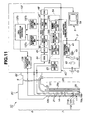
- an electronic endoscope system 1C comprises an electronic endoscope 2C of the third embodiment, light equipment 3 which supplies illumination light to this electronic endoscope 2C, an image processing apparatus (signal processing apparatus) 4C which performs signal processing to image pickup means embedded in the electronic endoscope 2C, and a monitor 5 corresponding to a Hi-Vision TV (this is abbreviated as HDTV) system, showing an endoscope image, by inputting a standard video signal outputted from the image processing apparatus 4C.
- HDTV Hi-Vision TV
- the electronic endoscope 2C of this embodiment has an insertion unit 7 which is slender and is inserted into a test object, an operation unit 8 which is provided in a rear end of this insertion unit 7, and which an operator such as an expert holds and operates, and a cable portion 9 extended from this operation unit 8.
- a rigid distal end portion 11 is provided in an end of the insertion unit 7, and an image pickup unit 119 and the like which are mentioned later are provided in this distal end portion 11.
- a light guide 14 which transmits illumination light is inserted, and a rear end side of this light guide 14 extends through the cable portion 9 to a light guide connector 15 provided in its end portion.
- illumination light is supplied to a rear end surface of the light guide 14 from the light equipment 3.
- the illumination light supplied from the light equipment 3 is transmitted by the light guide 14, and is further emitted forward through illumination lenses 16a and 16b (refer to FIG. 14) mounted on an illumination window with facing the end surface fixed to the distal end portion 11 to illuminate objects such as an affected part in a body cavity.
- An observation window (or image pickup window) is provided in the distal end portion 11 adjacent to the illumination window, and on this image pickup window is provided, an image pickup unit 119 comprising an objective lens system (or an objective optical system) 117 which images an optical image of an illuminated object, and, for example, a charge coupled device (this is abbreviated as a CCD) 118 as an image pickup device whose light-receiving surface (or photo-electric conversion surface) is arranged at an image forming position of this objective lens system 117.
- a charge coupled device this is abbreviated as a CCD
- One end of a signal cable 21 is connected to the image pickup unit 119, the signal cable 21 inserted into the insertion unit 7 is further inserted inside the cable portion 9, and another end is connected to a signal connector 22 in its rear end.
- the CCD 118 is driven with a CCD drive signal from a CCD driving unit 23 of the image processing apparatus 4C, and the CCD 118 outputs an image signal (image pickup signal) which performed photo-electric conversion.
- a video signal is generated by this image pickup signal being given signal processing in the image processing apparatus 4C, and an endoscope image is shown on the monitor 5.
- a channel 25 which makes various treatment tools insertable is provided.
- This channel 25 comprises a channel distal end opening (this is also called a distal end opening or a forceps opening) 26 which opens in the distal end portion 11, a treatment tool insert port 27 near a front end of the operation unit 8, and a channel tube 25a which connects the distal end opening 26 and the treatment tool insert port 27.
- the CCD 118 is a mosaic color filter type CCD equipped with a complementary mosaic color filter, and a pixel pitch is 2.5 ⁇ m and a pixel count effective in monitor display is 1,300,000 pixels.
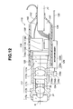
- the objective lens system 117 which is constructed of a varifocal optical system where an angle of view hardly changes when changing a focal position whose maximum angle of view is about 120° to 140° is used, it is made possible to form an image on the CCD 118 in a high resolution from a close-up view (near point side) to a distant view (far point side) as shown in FIG. 13 by moving forward and backward a doublet 117d on an optical axis O of the objective lens system 117 with an actuator 129 as explained in FIG. 12.
- Fno (F-number) is set at about 10.0 or less so as not to exceed a diffraction limit of light. In addition, it is set so as to obtain the highest resolution when an object distance is at the time of the close-up view.
- FIG. 12 A configuration of the image pickup unit 119 in this embodiment will be explained using FIG. 12.
- spacing between the lenses 117b and 117c is set by a spacer 32.
- the first, second, and third lenses 117a, 117b, and 117c which construct the objective lens system 117 and are arranged sequentially from its end side are a plano-concave lens, a biconvex lens, and an infrared cut-off filter, respectively.
- a lens holding frame portion 134a by which the doublet 117d is held is provided slidably in a direction of the optical axis O of the objective lens system 117.
- a parallel plate lens 117e and a CCD chip 118b are fixed at a position in a rear side of the lens holding frame portion 134a.
- the CCD 118 comprises a sealing glass 118a, the CCD chip 118b whose light-receiving surface (image pickup plane) is protected by this sealing glass 118a, a CCD substrate 118c connected to the CCD chip 118b, and CCD drive parts 118d implemented in this CCD substrate 118c.
- the CCD substrate 118c is electrically connected to the CCD chip 118b with bump connection or the like.
- the CCD drive parts 118d such as a coupling capacitor and a transistor for current amplification, are soldered.
- the sealing glass 118a for protecting the light-receiving surface of the CCD chip 118b is fixedly bonded on this light-receiving surface with an optical adhesive or the like.
- the lens frame 31 is fit with the CCD frame 133 so as to be movable in parallel 1 in the direction of the optical axis of the objective lens system 117, and the CCD chip 118b is fixedly bonded to the CCD frame 133 so that the optical axis of the above-described objective lens system 117 and the light-receiving surface of the above-described CCD chip 118b may become perpendicular.
- the doublet 117d with, for example, positive power (refractive power) which is arranged in the CCD frame 133 is held by the lens holding frame portion 134a which fits to an inner peripheral surface of the CCD frame 133 and becomes movable, and this lens holding frame portion 134a is connected to an actuator connecting portion 134c outside the CCD frame 133 through an arm portion 134b which penetrates the inside of a long groove 133a provided in the CCD frame 133.
- a moving lens frame 134 which moves the doublet 117d is formed of the above-mentioned lens holding frame portion 134a, arm portion 134b, and actuator connecting portion 134c.
- an actuator 129 which moves the doublet 117d with the moving lens frame 134 through the actuator connecting portion 134c comprises an actuator moving portion 129a connected to the actuator connecting portion 134c, and an actuator body 129b which moves this actuator moving portion 129a in a direction parallel to the optical axis O of the objective lens system 117.
- This actuator body 129b is fixed by an outer periphery side of the CCD frame 133.
- This actuator body 129b is connected to an actuator driving unit 136 (refer to FIG. 11) provided in the image processing apparatus 4C through a signal line 135, and the actuator body 129b operates with an actuator drive signal from this actuator driving unit 136. It is made that the actuator body 129b can move the actuator moving portion 129a to a rear side, which becomes in a side of the actuator body 129b, according to this actuator drive signal, and can move it to a front side separated from the actuator body 129b.
- This actuator driving unit 136 generates (outputs) an actuator drive signal corresponding to a control signal from the CPU 137C which constructs an auto-focusing unit (a focus control unit in this embodiment) 137 provided in the image processing apparatus 4C.
- the doublet 117d is in a state of being set in an approximately center of a movable range (moving range), and is set at a position shown by an alternate long and two short dashes line in FIG. 13 in the case of a set state at the time of the close-up view that it is moved to a most front side with the actuator drive signal to become in a state of forming an image of the close-up view, which is focused in the near point side, on the CCD chip 118b in a high resolution within a range of 5.2 mm to 10 mm of depth of field in this state.
- the doublet 117d is set at a position in a most rear side shown by a continuous line in FIG. 13, and this state becomes a set state at the time of the distant view which becomes the far point side.
- this set state at the time of the distant view it becomes in a state of focusing on the distant view and forming an image of the distant view on the CCD chip 18b in a predetermined resolution in a state that a depth of field is large, that is, 10 mm to 100 mm.
- FIG. 13 is a diagram for explanation of operation, and is shown with assigning reference numerals only to a part of components.
- a CCD protective frame 138 protecting mechanically is arranged from the CCD frame 133 to a connecting portion of the signal cable 21 with the CCD substrate 118c through the CCD chip 118b.
- a notched portion is provided at a position near a blackface portion of the CCD chip 118b, and a heat radiation member 139 which is good in thermal conductivity and is formed with, for example, an aluminum alloy or a copper alloy is arranged so as to be inserted from this notched portion.
- a cable 140 for heat radiation where metal being good in thermally conductivity is used as a conductor is mechanically connected to this heat radiation member 139 with soldering, an adhesive, or the like.
- a sealing resin 141 is filled, and a vicinity of the CCD chip 118b is sealed by a tube 142 with heat shrinkage nature.
- the cable 140 for heat radiation is soldered to a member with large heat capacity, for example, the distal end portion 11 of the insertion unit 7.
- the signal cable 21 is covered with a Teflon (registered trademark) sheath on it after making a plurality of coaxial lines and a plurality of solid wires twisted, wrapping a tape made of a fluorocarbon resin over it, winding copper wire as a package shield over it, and further wrapping a tape made of a fluorocarbon resin over it.
- Teflon registered trademark
- the image pickup unit 119 which includes the objective lens system 117 that an outer diameter of the first lens 117a in an end is ⁇ 2.8 mm, the channel distal end opening 26, an air-supplying and water-supplying nozzle 143 which supplies water and air to an outer surface of the objective lens system 117 to remove a waste material which adheres to it, and the illumination lenses 16a and 16b for illuminating an object with light transmitted (guided) by the light guide 14 connected to the light equipment 3 are provided.
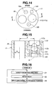
- the image pickup unit 119 is mounted on the distal end portion 11 so that a vertical direction on the monitor 5 when an image of an object is picked up and is shown on the monitor 5 may coincide with a vertical direction of the distal end portion 11 of the insertion unit 7 shown in FIG. 14.
- a tube with an inner diameter of 2.8 mm which is made of Teflon (registered trademark) is used for the channel tube 25a in this embodiment.
- the optical axis O of the objective lens system 117 and the distal end opening 26 are arranged in parallel, and in this embodiment, a distance D between a center (optical axis O) of the objective lens system 117 and a central axis of the distal end opening 26 is set, for example, to 6 mm. Doubleness of a radius R of this distal end opening 26 is 2.8 mm which is the same as an inner diameter of the channel tube 25a.
- the light equipment 3 has a lamp 40, and illumination light of this lamp 40 is incident into an incident end face of the light guide 14 in the light guide connector 15 through a condenser lens 43, after transmitted light volume is adjusted by an opening of an aperture 42 driven by an aperture driving unit 41.
- the illumination light is further emitted to an object side through the illumination lenses 16a and 16b from an end of the light guide 14 as mentioned above.
- the light guide 14 is branched into two lines in the insertion unit 7, and as shown in FIG. 14, in the distal end portion 11, the illumination light is emitted respectively from the illumination lenses 16a and 16b arranged in two places.
- the image processing apparatus 4C has a CDS circuit 44 where an image signal from the CCD 118 is inputted, and it is converted into a digital signal by an A/D converter 45 after a signal component is extracted by this CDS circuit 44.
- the digital image signal converted by this A/D converter 45 is inputted into a signal conversion unit 46 which generates a video signal which is constructed of a brightness signal and a chrominance signal.
- the video signal generated by this signal conversion unit 46 is inputted into an image processing unit 47 which performs various image processings such as ⁇ correction.
- an output signal of this image processing unit 47 is inputted into a D/A converter 48 and is converted into a video signal corresponding to an analog HDTV system, it is outputted to the monitor 5.
- the brightness signal from the signal conversion unit 46 is inputted into an automatic dimming unit 54 which generates an automatic dimming signal, and the automatic dimming signal is generated by this automatic dimming unit 54.
- This automatic dimming unit 54 comprises a treatment tool detection unit 54a which detects a treatment tool, a brightness detection unit 54b which detects an average level of the brightness signal inputted from this treatment tool detection unit 54a, and a dimming signal generating unit 54c which compares the average level of the detected brightness signal with a reference value which becomes a reference and outputs a difference signal from the reference value as an automatic dimming signal.
- the treatment tool detection unit 54a detects, for example, with reflected light volume and color of a treatment tool that the treatment tool enters in a visual field of the image pickup unit 119 (in other words, an image of the treatment tool is formed on the light-receiving surface of the CCD 118).
- the brightness detection unit 54b detects peak brightness (light volume) near in a region where an image of a treatment tool is formed, and mean brightness (light amount) near this region when the treatment tool is detected in the treatment tool detection unit 54a.
- this brightness detection unit 54b detects peak brightness and mean brightness in a whole screen when a treatment tool is not detected in the treatment tool detection unit 54a.
- the dimming signal generating unit 54c generates an automatic dimming signal which adjusts illumination light volume of the light equipment 3 so that an signal with proper brightness may be obtained by the peak brightness or mean brightness signal from the brightness detection unit 54b, and outputs it to the aperture driving unit 41 of the light equipment 3.
- the automatic dimming signal of the automatic dimming unit 54 is inputted into the aperture driving unit 41 of the light equipment 3, and the aperture driving unit 41 adjusts an opening amount of the aperture 42 automatically according to the automatic dimming signal and performs control so as to obtain an image with brightness which is suitable for observation and is equivalent to the reference value of the dimming signal generating unit 54c.
- the brightness signal of the signal conversion unit 46 is inputted into a brightness detection unit 137a which constructs the auto-focusing unit 137, and brightness of an image is detected by the brightness detection unit 137a.
- an output signal of the image processing unit 47 is inputted into a contrast detection unit 137b which constructs the auto-focusing unit 137, and contrast of the output signal is detected by the contrast detection unit 137b.
- Brightness information detected by the brightness detection unit 137a and contrast information detected by the contrast detection unit 137b are inputted into the CPU 137C, this CPU 137C performs, for example, hill-climbing type auto-focus control (this will be mentions later in FIG. 16) by brightness information and contrast information.
- the electronic endoscope 2C of this embodiment adopts a varifocal optical system (thus, a variable focal position optical system) where focal length changes without an angle of view hardly changing according to movement by arranging a part of the doublet 117d in the objective lens system 117 movably in a direction of the optical axis O, and making it continuously movable within a range from a position at the time of a close-up view to a position at the time of a distant view.
- a varifocal optical system thus, a variable focal position optical system
- this doublet 117d by performing focus control of this doublet 117d by the auto-focusing unit 137 to set it in an always-focused state within a range from the close-up view to the distant view, it is made possible to pick up an image in a state of keeping a high resolution and a predetermined depth of field.
- this embodiment adopts the configuration that it is easy to secure a large angle of visibility (angle of view) even when it is set as the close-up view, and to perform fine treatment with keeping an end side of a treatment tool, protruded from the distal end opening 26 of the channel 25, within a visual field also when the treatment tool is used.
- the end side of the treatment tool 28 inserted in the channel 25 is protruded from the distal end opening 26, it is made that the end side of the treatment tool 28 enters in a visual field of the image pickup unit 119 in an object distance in a side of a close-up view that a high resolution of making, for example, black and white in a 35- ⁇ m pitch discriminable is obtained, and in other words, that an image of the end side of the treatment tool 28 is formed on the light-receiving surface of the CCD 118.
- the light guide connector 15 of the electronic endoscope 2C is connected to the light equipment 3, and the signal connector 22 is connected to the image processing apparatus 4C.
- a cable of the monitor 5 is connected to a video output terminal of this image processing apparatus 4C to make it possible to perform endoscopy.
- a power switch which is not shown is turned ON for illumination light from the light equipment 3 to be supplied to the light guide 14, and the illumination light is emitted from the illumination lenses 16a and 16b through the light guide 14 to make it possible to illuminate an object an image of which is picked up with the image pickup unit 119.
- a power switch which is not shown is turned ON for illumination light from the light equipment 3 to be supplied to the light guide 14, and the illumination light is emitted from the illumination lenses 16a and 16b through the light guide 14 to make it possible to illuminate an object an image of which is picked up with the image pickup unit 119.
- it is made in a state that an image image-captured with the CCD 118 of the image pickup unit 119 is shown on the monitor 5 through the image processing apparatus 4C.
- the insertion unit 7 of the electronic endoscope 2C is inserted into a patient's body cavity, and the distal end portion 11 of the insertion unit 7 is made in a state that an object of a region, which is given endoscopy, such as an affected part in the body cavity can be observed.
- the objective lens system 117 in the image pickup unit 119 provided in the distal end portion 11 forms an optical image of the object on the light-receiving surface of the CCD 118.
- the image which is imaged on the light-receiving surface of the CCD 118 is given photo-electric conversion to be converted into an image signal.
- the image signal is inputted into the CDS circuit 44 of the image processing apparatus 4C through the signal cable 21 and the signal connector 22.
- This image signal has a waveform including reset noise and the like besides signal components, and a signal in a baseband where the signal components are extracted is generated by the CDS circuit 44.
- An output signal of this CDS circuit 44 is inputted into the A/D converter 45, and the A/D converter 45 converts into a digital signal the image signal which is an analog signal.
- the image signal converted into the digital signal is converted into a video signal by the signal conversion unit 46.
- this signal conversion unit 46 is converted into, for example, video signals such as a brightness signal which is obtained by averaging signal outputs of pixels of adjacent four kinds of color filters, and color-difference signals obtained from differences between pixel signal outputs of respective colors.
- the video signals are given contrast adjustment, color adjustment, display size adjustment, and the like which are suitable for monitor display by the image processing unit 47.
- the D/A converter 48 converts it into a video signal corresponding to an analog HDTV system which can be shown on the monitor 5.
- the monitor 5 shows an image of an object (image-captured by the CCD 118), corresponding to the inputted HDTV video signal, on a monitor screen 5a.
- the automatic dimming unit 54 detects brightness (specifically, peak brightness or mean brightness) of a whole screen by the brightness detection unit 54b, and outputs it to the dimming signal generating unit 54c.
- This dimming signal generating unit 54c outputs a control signal, and specifically, an automatic dimming signal to the light equipment 3 so as to increase brightness when a screen is dark.
- the screen when the screen is too bright, it outputs the automatic dimming signal as a control signal which controls the light equipment 3 so as to perform dimming.
- the aperture driving unit 41 in the light equipment 3 drives the aperture 42 to adjust volume of illumination light which is incident into a rear end of the light guide 14 through the aperture 42 from the lamp 40 so as to become proper light volume.
- the treatment tool 28 By inserting the treatment tool 28 into the channel 25 to protrude the treatment tool 28 through the distal end opening 26 of the distal end portion 11 of the insertion unit 7 from its end surface, the treatment tool enters in the visual field of the image pickup unit 119.
- the treatment tool detection unit 54a detects, for example, from color of the treatment tool 28, reflected light of the treatment tool 28, or the like that the treatment tool 28 enters in the visual field, and detects brightness in peak brightness or mean brightness in a certain region about the above-described treatment tool 28 as a center.
- the dimming signal generating unit 54c outputs the automatic dimming signal as a control signal so as to dim the light of the light equipment 3 when the brightness around the above-described treatment tool 28 is too bright, or to brighten the light of the light equipment 3 when being too dark.
- the aperture driving unit 41 in the light equipment 3 drives the aperture 42 to adjust volume of illumination light which is incident into an incident end of the light guide 14 through the aperture 42 from the lamp 40.
- this automatic dimming signal it is possible to perform the automatic dimming of the brightness near the region where the treatment tool 28 enters in the visual field in the image pickup unit 119 so as to become brightness suitable for observation.
- the doublet 117d which constructs the objective lens system 117 performs control by the auto-focusing unit 137 so that the object image may be always formed on the light-receiving surface of the CCD 118 in a focused state.
- the brightness detection unit 137a of the auto-focusing unit 137 detects mean brightness of each frame from a brightness signal from the signal conversion unit 46, and outputs it to the CPU 137C.
- the contrast detection unit 137b detects contrast in each frame from a brightness signal in a high frequency region in an output signal of the image processing unit 47, and outputs it to the CPU 137C.
- the CPU 137C judges whether the brightness detected by the brightness detection unit 137a is a predetermined value or larger, and detects a focus condition by a hill-climbing system with the contrast information in the brightness signal in the high frequency region detected by the contrast detection unit 137b when exceeding the predetermined value, and it sets the doublet 117d at a focused position.
- FIG. 16 shows contents of processing which performs hill-climbing type auto-focusing (this is written as AF in FIG. 16).
- the CPU 137C judges a lens-moving direction. As shown in FIGS. 12 and 13, it performs judgment processing of which direction becomes a hill-climbing direction (direction where contrast becomes large) at a lens position at the start when performing this hill-climbing type auto-focusing.
- the CPU 137C controls the actuator driving unit 136, moves the doublet 117d to one side through the actuator 129, and judges whether the contrast information which is outputted from the contrast detection unit 137b becomes large before and after movement at that time. Then, the CPU 137C judges that a direction where contrast becomes large is the lens moving direction to move the doublet 117d in the direction.
- the CPU 137C detects a peak value of contrast in the case of moving the doublet 117d in the direction where the contrast becomes large.
- a contrast value in that case becomes smaller than the peak value.
- a peak value is detectable by moving the doublet 117d to a position of passing over the peak value slightly.
- the CPU 137C controls the actuator driving unit 136 to return the doublet 117d to the position corresponding to the peak value.
- the doublet 117d it is possible to set the doublet 117d at the focusing position.
- step S1 it is possible to always keep a focused state and also when a distance to an object changes, it is possible to form an image of the object on the CCD 118 in a high resolution with keeping a predetermined depth of field. Then, an image of the object in the state of being formed on the CCD 118, that is, an image with a high resolution in the state of keeping the predetermined depth of field is shown on the monitor 5.
- focus control is performed using contrast detected, it is also acceptable to perform control that priority is given to a distant view position over focus control by the contrast, when a brightness level of a brightness signal is small (when it is a dark image).
- An operator inserts a treatment tool to be used in the treatment tool insert port 27 provided around the operation unit 8.
- the treatment tool inserted from the treatment tool insert port 27 passes inside the channel 25 of the channel tube 25a in the insertion unit 7, and is quided to a side of the distal end portion 11 of the insertion unit 7.
- an end of the treatment tool 28 projects from the channel distal end opening 26 of the distal end portion 11.
- the treatment tool 28 starts to enter in the visual field of the image pickup unit 119 when a protrusion amount from the end surface of the distal end portion 11 becomes at 1.38 mm or more, and almost the whole end of the treatment tool 28 enters in the visual field when being protruded by 2.45 mm.
- a depth of field is set in 5.2 mm to 10 mm, and the end side of the treatment tool 28 enters in the visual field of the image pickup unit 119 securely and becomes visible also on the monitor 5.
- FIG. 18 shows a schematic diagram in the case of inserting the insertion unit 7 of the electronic endoscope 2C of this embodiment into a body cavity, and not only picking up an image of a treatment object region side in the body cavity with the image pickup unit 119 provided in the distal end portion 11, but also protruding the treatment tool 28 from the distal end opening 26 to perform treatment.
- brightness contrast G (MTF) is defined as follows.
- the brightness contrast G is defined in this way, in the image pickup unit 119 constructed as mentioned above, when an image of the object of a black and white pair of stripes 60 with a pitch of 35 ⁇ m is picked up at the time of an object distances of 5.2 mm to 6.8 mm in a state of being set at the near point, the brightness contrast G of the white stripe and black stripe an image of which is formed on the CCD light-receiving surface becomes 10% or more.
- the above-described image signal is inputted into the image processing unit 47 through the CDS circuit 44, A/D converter 45, and signal conversion unit 46, and is given, for example, gamma processing suitable for the monitor 5, and low-pass filtering of removing noise.
- contrast I (Imax - Imin)/(Imax + Imin), and in that case, (when an object that a pitch of the above-mentioned black and white pair of stripes is 35 ⁇ m is image-captured) it is outputted so that the contrast I may become 10% or more.
- the black and white pair of stripes at a pitch of 35 ⁇ m image-captured with the image pickup unit 119 becomes visible as a black and white pair of stripes on the monitor 5. In this way, it becomes observable in a state of being easy to be identified when the contrast I becomes 10% or more.
- a black and white pair of stripes 60 at a 35- ⁇ m pitch is arranged at the position, and in that case, photo-electric conversion is performed by the CCD 18, and since, for example, the contrast I in a brightness signal which forms a video signal outputted from the signal conversion unit 46 becomes 10% or more as mentioned above, it becomes possible to visually identify the black and white pair of stripes 60 at a 35- ⁇ m pitch on the monitor 5.
- FIG. 18 shows a state that the treatment tool 28 is protruded from the distal end opening 26 of the channel, and by further protruding it forward after the end of the treatment tool 28 enters into the visual field of the image pickup unit 119, the end of the treatment tool 28 becomes in a state of an object distance d where the black and white pair of stripes 60 at a 35- ⁇ m pitch is visible.
- the object distance d becomes in a state of satisfying the following condition from Formula 6: d ⁇ D - Lh + R ⁇ tan 90 ⁇ ° - ⁇ / 2
- the varifocal optical system since the varifocal optical system is used, by changing a focal length of the objective optical system to the distant view side, it is possible to grasp a wide range state to smoothly perform treatment.
- This embodiment exhibits the following effects.
- the end side of the treatment tool 28 protruded from the distal end opening 26 of the channel 25 is visible on the monitor 5 in a distance where the black and white pair of stripes at a 35- ⁇ m pitch image-captured with the above-described image pickup unit 119 can be visually identified on the monitor 5, it is possible to improve operability due to an angle of view at the time of amplified observation becoming narrow in an endoscope using a conventional zoom optical system.
- a distance of a black and white pair of stripes at a 35- ⁇ m pitch being visible on the monitor is 5.2 mm to 6.8 mm in the state of being set in the near point side
- the light equipment 3 controls illumination light volume so that brightness around the treatment tool 28 may become optimum when it becomes in a state that the treatment tool 28 is inserted and its end is shown on the monitor 5, it becomes easy to perform treatment.
- the pixel pitch of CCD118 is 2.5 ⁇ m, that effective pixel count is 1,300,000, that a maximum angle of view of the image pickup unit 119 is 138°, that a depth of field in the near point side is 5.2 mm to 10 mm, and that a distance between the optical axis O of the image pickup unit 119, and the center of the distal end opening 26 is 6 mm, it is not limited to these.
- the effectiveness pixel count of the CCD 118 is 1,300,000 pixels in the above-described explanation, it is possible to obtain similar effects with about 1,500,000 pixels in the case of a mosaic color filter system, and in this case, it is possible to obtain such an effect that it is possible to further enlarge a distance in which a highest resolution can be obtained.
- a complementary color-based mosaic filter type color CCD in this embodiment, it is not limited to this, and when a system which uses switching type or other type trichromatic light as illumination light, fetches an object image in a monochrome (black and white) CCD with synchronizing with the trichromatic light which is sequentially radiated, and colorizes it by an image processing apparatus is used in an electronic endoscope, it is possible to obtain a similar effect also in this system by fulfilling the above-mentioned conditions.
- an angle of view As for an angle of view, an angle of view of 100° or more used in a common endoscope in consideration of surrounding observation capability is preferable, and there is such an effect that a wider angle of view makes a treatment tool detection distance shorter.
- the image processing apparatus 4C and the monitor 5 in this embodiment are explained as those corresponding to the HDTV video signal, they are not limited to this, and for example, it is also sufficient to use a display system corresponding to a high-resolution monitor such as SVGA or XGA.
- heat radiation to an end portion material of the insertion unit 7 with the heat radiation member 139 and the cable 140 for heat radiation is disclosed as means of radiating heat of the CCD 118, it is also sufficient to adopt such structure that the cable 140 for heat radiation is not provided in the heat radiation member 139, the thermally conductive portion of the end portion material of the insertion unit 7 is made to approach a portion which faces the heat radiation member, and heat is radiated through a thermally conductive sealing resin or the like.
- the cable 140 it is also sufficient to use a part of the signal cable 21 as the cable 140 for heat radiation.
- FIG. 19 shows entire configuration of an electronic endoscope system 1D equipped with a fourth embodiment.
- This electronic endoscope system 1D comprises an electronic endoscope 2D which is different in a part from the electronic endoscopes 2C in FIG. 11, a video processor 4D equipped with a CPU 71 with a two-step (auto) focus control function 71a instead of the auto-focusing unit 137 in the video processor 4C in the third embodiment.
- a light source unit 3 and a monitor 5 are the same configuration as those in the third embodiment.
- FIG. 20 is a front view in view of an end surface of an distal end portion 11 of an insertion unit 7 in the electronic endoscope 2D of this embodiment from a front
- FIG. 21 is a sectional view taken on line D-D in FIG. 20
- FIG. 23 shows a monitor display image at the time of protruding a treatment tool 28 from the distal end portion 11.
- the image pickup unit 119B has an objective lens system 172 with a varifocal point that a maximum angle of view becomes 160°, for example, in a state of being set to a near point side (close-up view), and a lens having a meniscus shape is adopted as a first lens 172a which is the forefront of this objective lens system 172.
- the image pickup unit 119B which includes the objective lens system 172 that an outer diameter of the first lens 172a is ⁇ 2.8 mm and a shape is a meniscus, a channel distal end opening 26B, an air-supplying and water-supplying nozzle 143 which supplies water and air to an outer surface of the objective lens system 172 to remove a waste material which adheres to it, and illumination lenses 16a and 16b for radiating and illuminating an object with light emitted from an end surface of a light guide transmitting illumination light from a light equipment 3 are provided.
- the image pickup unit 119B is mounted on an end of an insertion unit so that a vertical direction on the monitor 5 when an image of an object is picked up and is shown on the monitor 5 may coincide with a vertical direction of the end of the insertion unit shown in FIG. 20.
- a treatment tool channel 25 with an inner diameter of ⁇ 2.8 mm is arranged in a left oblique down direction which deviates a little from a horizontal direction, to the image pickup unit 119B, as shown in FIG. 20, with letting a vertical direction of the distal end portion 11 be a Y-axis and letting a crosswise direction be an X-axis, a straight line which connects a central axis of the treatment tool channel 25 and an optical axis O of the image pickup unit 119B forms an angle of ⁇ to the above-described X-axis.
- the optical axis O of the objective lens system 172 and the distal end opening 26B are arranged in parallel, and in this embodiment, a distance D between the center (optical axis O) of the objective lens system 172 and a central axis of the distal end opening 26B is set as 6 mm.
- the first lens 172a, a second lens 172b, and a third lens 172c shown in FIG. 21 are mounted on a first lens frame 31, a doublet 117d is arranged movably with a lens holding frame 134 similarly to the third embodiment in the CCD frame 133 fitting to this first lens frame 31, and the doublet 117d is moved in a direction of the optical axis O through an actuator 129.
- the CPU 71 provided in the video processor 4D moves the doublet 117d fundamentally instead of performing auto-focus control continuously in the third embodiment to perform focus control so that a focal position of the objective lens system 172 may become in an approximately focused state between two positions of a close-up view position and a distant view position.
- it performs two-step focus control (pseudo one by auto switching).
- the CPU 71 reads ID information of the electronic endoscope 2D connected to the video processor 4D from scope ID memory 74, and stores optical characteristic information of the image pickup unit 119B of this electronic endoscope 2D in a RAM 71C.
- This optical characteristic information is information with regard to characteristics of a typical contrast change or a resolution at the time when an object distance changes in the case that the doublet 117d is set at a position at the time of a close-up view, and the case that it is set at a position at the time of a distant view.
- the CPU 71 checks temporal responses and others of the contrast information in the state of being set at one position where the doublet 117d is actually set, and judges from the change whether it is possible to obtain a larger contrast value by changing it to another position, that is, whether it is closer to a focused state, by referring to the optical characteristic information stored in the RAM 71C.
- the CPU 71 controls an actuator driving unit 136 to set the doublet 117d at the another position.
- the CPU 71 monitors the contrast information in the state in time, and performs control so as to make a lens position become nearer to a focused state between two lens positions by performing a similar operation.
- the CPU 71 detects brightness information from a brightness signal from a signal conversion unit 46, further detects contrast information from an image processing unit 47, monitors temporal responses of the contrast information in a state of being in more than predetermined brightness as mentioned above, judges whether it should be switched, by referring to the optical characteristic information, and controls the doublet 117d between the two positions according to the decision result. In addition, at the time when predetermined brightness is not obtained, or in an initial state, the CPU 71 performs control of setting it to the distant view position.
- the objective lens system 172 in both states shows different optical characteristics, respectively. For example, while it has a highest resolution at the time of the close-up view, it becomes a somewhat low resolution at the time of the distant view in comparison with the time of the close-up view, but it has a larger depth of field than that at the time of the close-up view. Specifically, an F-number is adjusted so that a depth of field may become 4.4 to 12 mm when the doublet 117d is set in the close-up view side, and a depth of field may become 9 to 100 mm when it set in the distant view side.
- a depth of field in the objective lens system 172 in a state of being set at the close-up view and that in a state of being set at distant view are set so as to continue (overlap) in a portion not less than a predetermined value
- the contrast I is sets so as to overlap in a portion having a predetermined value or more (for example, 10%) more in a range to a spatial frequency with a predetermined value.
- this image pickup unit 119B when an image of the object of a black and white pair of stripes with a pitch of 35 ⁇ m is picked up at the time of an object distance of 4.4 mm to 5.8 mm in a state of being set at the near point, the brightness contrast G of the white stripe and black stripe an image of which is formed on a CCD light-receiving surface becomes 10% or more.
- the image of the object of the black and white pair of stripes with a 35- ⁇ m pitch which is picked up on the light-receiving surface of the CCD 173 by the above-described objective lens system 172 is given photo-electric conversion. Then, difference between an image signal outputted from a pixel on which the white stripe is image-formed, and an image signal outputted from a pixel on which a black stripe is image-formed becomes 10% or more.
- the image signal is inputted into the image processing unit 47 through a CDS circuit 44, A/D converter 45, and signal conversion unit 46 to be given, for example, gamma processing suitable for the monitor, electric mask processing, and the like so as to make the contrast I of the white stripe and black stripe 10% or more, and is outputted to the monitor 5. Since it becomes possible to identify the white stripe and black stripe from the shown image by the contrast I becoming 10% or more in the case of the above-mentioned object, it is possible to observe it in a sufficient resolution. In this manner, according to this embodiment, the black and white pair of stripes at a pitch of 35 ⁇ m image-captured with the image pickup unit 119B becomes visible as a black and white pair of stripes on the monitor.
- the CPU 71 since a contrast value becomes small when an object distance becomes larger than that at the time of the close-up view, the CPU 71 performs control of switching the doublet 117d to the position at the time of the distant view when judging that it is possible to obtain a larger contrast value by the switching.
- FIG. 22 shows an operation of the two-step auto-focus control (more accurately, two steps approximate auto-focus control) in this embodiment.
- focusing is abbreviated to AF.
- the CPU 71 reads optical characteristic information from the scope ID memory 74 as initial setting at a first step S11, and stores it in the RAM 71C.
- the CPU 71 sets the typical contrast information, depth-of-field information, and resolution characteristic information from the optical property information in a state near to AF between the distant view position and close-up view position, as criteria of judgment of AF switching.
- the objective lens system 117 in this embodiment is set so that parts of depths of field in the focused states at respective positions may overlap.
- the CPU 71 performs control processing of setting the doublet 117d at the distant view position.
- the CPU 71 judges whether a current brightness level of the brightness signal is not less than a threshold value Vth, which is set beforehand, for judging a dark image state. Then, when judging that it is not more than this threshold value Vth, it returns to step S13 and these processings are repeated with keeping the distant view position.
- Vth a threshold value
- the doublet 117d is set at the distant view position. Since the insertion unit 7 of the electronic endoscope 2D is inserted into a body cavity, illumination light is emitted from the illumination lenses 16a and 16b provided in the end surface of the distal end portion 11, and an object such as an affected part is illuminated, lack of illumination light volume hardly arises when a distance to the object is small. For this reason, when the brightness level of the brightness signal is not more than the threshold Vth, it is considerable that there is the object far away. In addition, since an S/N ratio drops when a brightness level of a brightness signal is not more than the threshold Vth, high-precision focus control becomes difficult. For such a reason, when a brightness level of a brightness signal is not more than the threshold Vth, the doublet 117d is set at the distant view position.
- the CPU 71 judges whether the contrast value presently detected is nearer to the case in the distant view side (than the close-up view side), using the criteria of judgment.
- step S16 the CPU 71 performs control processing of setting the doublet 117d at the close-up view position.
- step S17 the CPU 71 judges whether the contrast value presently detected is nearer to the case in the close-up view side (than the distant view side). In the case of not fulfilling this condition, it returns to step S13 and performs the processing of setting it at the distant view position.
- the CPU 71 judges whether a current brightness level of the brightness signal is not less than the threshold value Vth, which is set beforehand, for judging a dark image state. Then, when judging that it is not more than this threshold value Vth, it returns to step S13. On the contrary, when judging that it is not less than the threshold value Vth, it returns to step S17.
- electric mask processing creates an octagonal display area 5b with an aspect ratio of 1:1.2 in the display screen of the monitor 5 as shown in FIG. 23, and makes an object image-captured with the image pickup unit 119B displayed in the octagonal display area 5b.
- a point P in a diagonal direction becomes a largest angle of view ( ⁇ max).
- the mask processing is performed so that 160° of angle of view of the objective lens system 172 may coincide with the above-described maximum angle ⁇ max of view.
- what an angle of view becomes narrowest on the monitor screen is a vertical direction, and, secondly an angle of view in a crosswise direction becomes narrow.
- the point P to become the above-described maximum diagonal is set so that an angle formed by a straight line which connects the point P and a screen center, and a horizontal direction on the monitor screen may be set at ⁇
- the image pickup unit 119B is arranged so that an X-axis direction of the distal end portion 11 of the insertion unit and the monitor horizontal direction may coincide as shown in FIG. 20, and hence, the treatment tool 28 protruded from the distal end opening 26B of the treatment tool channel 25 arranged in a position becoming the angle ⁇ to the X-axis is displayed as shown in FIG. 23 within the display area 5b from an approximately horizontal direction on the monitor 5, or more strictly, from a lower left point P which is a little lower than the horizontal direction.
- the treatment tool 28 starts to enter in the visual field of the image pickup unit 119B when a protrusion amount from the end surface of the distal end portion 11 becomes at 0.58 mm or more, and almost the whole end of the treatment tool 28 enters in the visual field when being protruded by 1.07 mm.
- the end side of the treatment tool 28 enters in the visual field of the image pickup unit 119B and becomes visible also on the monitor 5.
- This embodiment exhibits the following effects.
- the varifocal optical system that a focal distance changes is adopted as the objective optical system which constructs the image pickup unit 119B, it is possible to obtain an image with a higher resolution from the close-up view side to the distant view side than the case of a single focal optical system.
- the pixel pitch of CCD 173 is 2.8 ⁇ m
- that effective pixel count is 800,000
- that a maximum angle of view of the image pickup unit 119B is 160°
- that depth of field in the state of being set in the near point side is 4.4 mm to 12 mm
- the distance between the optical axis O of the image pickup unit 119B, and the center of the distal end opening 26 is 6 mm, it is not limited to these.
- the effectiveness pixel count is 800,000 pixels in this embodiment, it is possible to obtain similar effects with about 600,000 pixels in the case of the mosaic color filter system, and in this case, since the depth of field in the near point side is enlarged to spread the cross region in depth with the depth of field in the far point side, it is possible to obtain such an effect that it is possible to make focal switching more smooth.
- the display area 5b of the monitor screen 5a is made an oblong octagon where horizontal display size is longer than that in a vertical direction (longitudinal direction) as shown in FIG. 23, it is not limited to this case.
- the treatment tool 28 protruded from a distal end opening, displayed in a direction where display area is wider by arranging this distal end opening so as to correspond in the direction where the display area is wider (or larger) in the display area.
- the "direction where a display area is wider" here means a direction where restriction of a display area of an observed image displayed on a screen is few (or there is no restriction) in comparison with other directions because of electronic mask processing and the like.
- the CPU 71 has the three-step auto-focus control function 71b besides the two-step auto-focus control function 71a in, for example, the electronic endoscope system 1D of FIG. 19.
- this CPU 71 performs focus control in a two-step auto-focusing mode or a three-step auto-focusing mode according to a selection signal selected by the mode changeover switch SW1 provided, for example, in the operation unit 8 of the electronic endoscope 2D.
- optical characteristic information unique in the electronic endoscope 2D is stored in the scope ID memory (memory) 74.
- the optical characteristic information with regard to the contrast values and the like at the time of setting the doublet 117d at a midpoint set between the near point and far point besides the near point and far point is stored.
- information of driving (moving) the doublet 117d at the position of the midpoint is also stored.
- the CPU 71 of the video processor 4D reads the optical characteristic information to store it in, for example, the RAM 71C, and performs the two-step focus control or three-step focus control in the fourth embodiment.
- a control method of performing the three-step focus control is similar to that of the two-step.
- the CPU 71 monitors temporal responses of the contrast information in the state, and judges whether switching between the state of the near point and the midpoint, in that case.
- the CPU 71 monitors the temporal responses of the contrast information and judges which of the near point side and far point side is suitable as a switched side according to a changing direction to the near point side, or to the far point side. For this reason, it is also possible to perform the three-step focus control by the control similar to the case of the fourth embodiment.
- FIG. 25 shows a portion of the CPU 71 in a second modified example. As shown in FIG. 25, for example, it is also sufficient that the CPU 71 performs the two-step autofocus control function 71a or the two-step manual control function 71d according to a mode switching instruction signal of the mode changeover switch SW1.
- the two-step auto-focus control function 71a is the same as what is explained in the fourth embodiment.
- the CPU 71 moves the doublet 17d to the near point side when a near point instruction switch in the manual operation switch SW2 is operated.
- the CPU 71 performs the control operation of moving the doublet 117d to the far point side.
- the image processing apparatus 4D and the monitor 5 in this embodiment are explained as those corresponding to the HDTV video signal, they are not limited to this, but, it is also sufficient to use, for example, what corresponds to an NTSC or PAL video signal. In addition, it is also sufficient to use what conforms to a VGA system or an SVGA system.
- the electronic endoscope While being able to insert an insertion unit into a body cavity and to pick up an image of objects such as an affected part in a state of being observable in a high resolution in a close-up view side, the electronic endoscope makes it possible to secure a resolution needed also in a distant view side, and to observe an end side of a treatment tool, which is inserted into a channel, with entering it in an observation visual field even in a state that a projection amount from a distal end opening of a channel is small.
Applications Claiming Priority (3)
| Application Number | Priority Date | Filing Date | Title |
|---|---|---|---|
| JP2004145697A JP4377745B2 (ja) | 2004-05-14 | 2004-05-14 | 電子内視鏡 |
| JP2005109094A JP4464858B2 (ja) | 2005-04-05 | 2005-04-05 | 電子内視鏡 |
| PCT/JP2005/008800 WO2005110202A1 (fr) | 2004-05-14 | 2005-05-13 | Endoscope électronique |
Publications (2)
| Publication Number | Publication Date |
|---|---|
| EP1757221A1 true EP1757221A1 (fr) | 2007-02-28 |
| EP1757221A4 EP1757221A4 (fr) | 2014-04-09 |
Family
ID=35393935
Family Applications (1)
| Application Number | Title | Priority Date | Filing Date |
|---|---|---|---|
| EP05739184.9A Pending EP1757221A4 (fr) | 2004-05-14 | 2005-05-13 | Endoscope électronique |
Country Status (7)
| Country | Link |
|---|---|
| US (2) | US7828721B2 (fr) |
| EP (1) | EP1757221A4 (fr) |
| KR (1) | KR100911793B1 (fr) |
| AU (1) | AU2005244353B2 (fr) |
| CA (1) | CA2567737A1 (fr) |
| RU (1) | RU2006144442A (fr) |
| WO (1) | WO2005110202A1 (fr) |
Cited By (3)
| Publication number | Priority date | Publication date | Assignee | Title |
|---|---|---|---|---|
| EP2055224A1 (fr) * | 2007-10-31 | 2009-05-06 | Orangedental GmbH & Co. KG | Procédé autofocus et système correspondant |
| EP2196134A1 (fr) | 2008-12-09 | 2010-06-16 | Fujifilm Corporation | Appareil d'endoscope et son procédé de commande |
| EP2805665A1 (fr) * | 2012-01-17 | 2014-11-26 | Olympus Corporation | Appareil endoscopique, dispositif d'actionnement pour appareil endoscopique et procédé de commande pour appareil endoscopique |
Families Citing this family (62)
| Publication number | Priority date | Publication date | Assignee | Title |
|---|---|---|---|---|
| IL177040A0 (en) * | 2006-07-24 | 2006-12-10 | Wave Group Ltd | A discrete routine vaginal exam medical device |
| JP4310330B2 (ja) * | 2006-09-26 | 2009-08-05 | キヤノン株式会社 | 表示制御装置及び表示制御方法 |
| JP2009056105A (ja) * | 2007-08-31 | 2009-03-19 | Olympus Medical Systems Corp | 焦点距離可変付き内視鏡 |
| JP2009219573A (ja) * | 2008-03-14 | 2009-10-01 | Fujinon Corp | 内視鏡用画像処理装置及び内視鏡用画像処理方法 |
| JP2009219779A (ja) * | 2008-03-18 | 2009-10-01 | Toshiba Corp | 内視鏡のカメラヘッドおよびその製造方法 |
| JP2010022815A (ja) * | 2008-06-18 | 2010-02-04 | Olympus Corp | 内視鏡装置 |
| JP5289870B2 (ja) * | 2008-09-08 | 2013-09-11 | オリンパスメディカルシステムズ株式会社 | 内視鏡用撮像ユニット |
| EP2179687B1 (fr) * | 2008-10-22 | 2012-12-26 | FUJIFILM Corporation | Appareil d'endoscope et son procédé de commande correspondant |
| JP5422180B2 (ja) * | 2008-11-21 | 2014-02-19 | 富士フイルム株式会社 | 内視鏡装置およびその作動方法 |
| JP4585048B2 (ja) * | 2009-01-15 | 2010-11-24 | オリンパスメディカルシステムズ株式会社 | 内視鏡システム |
| US10165929B2 (en) | 2009-06-18 | 2019-01-01 | Endochoice, Inc. | Compact multi-viewing element endoscope system |
| US9642513B2 (en) | 2009-06-18 | 2017-05-09 | Endochoice Inc. | Compact multi-viewing element endoscope system |
| US11547275B2 (en) | 2009-06-18 | 2023-01-10 | Endochoice, Inc. | Compact multi-viewing element endoscope system |
| CA2765559C (fr) | 2009-06-18 | 2017-09-05 | Peer Medical Ltd. | Endoscope a cameras multiples |
| US9901244B2 (en) | 2009-06-18 | 2018-02-27 | Endochoice, Inc. | Circuit board assembly of a multiple viewing elements endoscope |
| US9872609B2 (en) | 2009-06-18 | 2018-01-23 | Endochoice Innovation Center Ltd. | Multi-camera endoscope |
| US9101268B2 (en) | 2009-06-18 | 2015-08-11 | Endochoice Innovation Center Ltd. | Multi-camera endoscope |
| US9101287B2 (en) | 2011-03-07 | 2015-08-11 | Endochoice Innovation Center Ltd. | Multi camera endoscope assembly having multiple working channels |
| US8926502B2 (en) | 2011-03-07 | 2015-01-06 | Endochoice, Inc. | Multi camera endoscope having a side service channel |
| US11278190B2 (en) | 2009-06-18 | 2022-03-22 | Endochoice, Inc. | Multi-viewing element endoscope |
| US11864734B2 (en) | 2009-06-18 | 2024-01-09 | Endochoice, Inc. | Multi-camera endoscope |
| US9713417B2 (en) | 2009-06-18 | 2017-07-25 | Endochoice, Inc. | Image capture assembly for use in a multi-viewing elements endoscope |
| US9706903B2 (en) | 2009-06-18 | 2017-07-18 | Endochoice, Inc. | Multiple viewing elements endoscope system with modular imaging units |
| US9402533B2 (en) | 2011-03-07 | 2016-08-02 | Endochoice Innovation Center Ltd. | Endoscope circuit board assembly |
| US9492063B2 (en) | 2009-06-18 | 2016-11-15 | Endochoice Innovation Center Ltd. | Multi-viewing element endoscope |
| WO2011001301A1 (fr) * | 2009-06-29 | 2011-01-06 | Koninklijke Philips Electronics N.V. | Procédé et appareil de suivi dans une intervention médicale |
| US8363097B2 (en) * | 2009-07-23 | 2013-01-29 | Smith & Nephew, Inc. | Endoscopic imaging system |
| JP5452282B2 (ja) * | 2010-02-26 | 2014-03-26 | オリンパス株式会社 | 固体撮像装置 |
| JP5346856B2 (ja) * | 2010-03-18 | 2013-11-20 | オリンパス株式会社 | 内視鏡システム、内視鏡システムの作動方法及び撮像装置 |
| WO2012018796A2 (fr) * | 2010-08-02 | 2012-02-09 | The Johns Hopkins University | Système et endoscope avec focalisation automatique |
| US9560953B2 (en) | 2010-09-20 | 2017-02-07 | Endochoice, Inc. | Operational interface in a multi-viewing element endoscope |
| US10080486B2 (en) | 2010-09-20 | 2018-09-25 | Endochoice Innovation Center Ltd. | Multi-camera endoscope having fluid channels |
| JP5944912B2 (ja) | 2010-10-28 | 2016-07-05 | エンドチョイス イノベーション センター リミテッド | マルチセンサ内視鏡のための光学系 |
| EP2648602B1 (fr) | 2010-12-09 | 2018-07-18 | EndoChoice Innovation Center Ltd. | Carte de circuit électronique flexible pour endoscope à caméras multiples |
| JP6054874B2 (ja) | 2010-12-09 | 2016-12-27 | エンドチョイス イノベーション センター リミテッド | マルチカメラ内視鏡用フレキシブル電子回路基板 |
| US11889986B2 (en) | 2010-12-09 | 2024-02-06 | Endochoice, Inc. | Flexible electronic circuit board for a multi-camera endoscope |
| US9101266B2 (en) | 2011-02-07 | 2015-08-11 | Endochoice Innovation Center Ltd. | Multi-element cover for a multi-camera endoscope |
| JP5948076B2 (ja) * | 2011-08-23 | 2016-07-06 | オリンパス株式会社 | フォーカス制御装置、内視鏡装置及びフォーカス制御方法 |
| US9456735B2 (en) * | 2012-09-27 | 2016-10-04 | Shahinian Karnig Hrayr | Multi-angle rear-viewing endoscope and method of operation thereof |
| JP5572141B2 (ja) * | 2011-09-30 | 2014-08-13 | 富士フイルム株式会社 | 内視鏡 |
| JP5951211B2 (ja) * | 2011-10-04 | 2016-07-13 | オリンパス株式会社 | 合焦制御装置及び内視鏡装置 |
| JP5315482B1 (ja) * | 2011-10-27 | 2013-10-16 | オリンパスメディカルシステムズ株式会社 | 内視鏡システム |
| KR20130059150A (ko) | 2011-11-28 | 2013-06-05 | 삼성전자주식회사 | 내시경용 대물 렌즈, 포커싱을 위한 액츄에이터 및 내시경 시스템 |
| EP2604172B1 (fr) | 2011-12-13 | 2015-08-12 | EndoChoice Innovation Center Ltd. | Connecteur rotatif pour endoscope |
| CA2798716A1 (fr) | 2011-12-13 | 2013-06-13 | Peermedical Ltd. | Endoscope a pointe amovible |
| JP5953049B2 (ja) * | 2012-01-24 | 2016-07-13 | オリンパス株式会社 | 内視鏡システム |
| ITMI20120948A1 (it) * | 2012-05-31 | 2013-12-01 | Milano Politecnico | Apparato miniaturizzato per visione endoscopica. |
| JP5485482B1 (ja) * | 2012-07-03 | 2014-05-07 | オリンパスメディカルシステムズ株式会社 | 内視鏡用対物光学系 |
| US9560954B2 (en) | 2012-07-24 | 2017-02-07 | Endochoice, Inc. | Connector for use with endoscope |
| JP6103849B2 (ja) * | 2012-08-02 | 2017-03-29 | オリンパス株式会社 | 内視鏡装置及び内視鏡装置の作動方法 |
| WO2014129310A1 (fr) * | 2013-02-20 | 2014-08-28 | オリンパスメディカルシステムズ株式会社 | Dispositif endoscopique |
| US9986899B2 (en) | 2013-03-28 | 2018-06-05 | Endochoice, Inc. | Manifold for a multiple viewing elements endoscope |
| US9993142B2 (en) | 2013-03-28 | 2018-06-12 | Endochoice, Inc. | Fluid distribution device for a multiple viewing elements endoscope |
| US10499794B2 (en) | 2013-05-09 | 2019-12-10 | Endochoice, Inc. | Operational interface in a multi-viewing element endoscope |
| EP3050484A4 (fr) * | 2013-09-24 | 2017-05-31 | Olympus Corporation | Dispositif d'endoscope et procédé de commande de dispositif d'endoscope |
| US9451876B2 (en) * | 2013-10-21 | 2016-09-27 | Olympus Corporation | Endoscope system and focus control method for endoscope system |
| CN204243344U (zh) * | 2014-10-11 | 2015-04-01 | 中兴通讯股份有限公司 | 一种射频单元 |
| JP6177387B2 (ja) * | 2016-06-08 | 2017-08-09 | オリンパス株式会社 | 内視鏡装置の合焦制御装置、内視鏡装置及び内視鏡制御装置の作動方法 |
| KR102041236B1 (ko) * | 2018-01-29 | 2019-11-06 | (주)커넥슨 | 다중 광원 장치 및 복합 필터를 포함하는 휴대용 내시경 및 이를 위한 다중 광원 장치 |
| DE112019003447T5 (de) * | 2018-07-06 | 2021-03-18 | Sony Corporation | Medizinisches Beobachtungssystem, medizinisches Beobachtungsgerät und Antriebsverfahren für das medizinische Beobachtungsgerät |
| US20210290037A1 (en) * | 2020-03-17 | 2021-09-23 | Sony Olympus Medical Solutions Inc. | Medical image processing apparatus and medical observation system |
| WO2023042354A1 (fr) * | 2021-09-16 | 2023-03-23 | オリンパスメディカルシステムズ株式会社 | Processeur d'endoscope, programme et procédé de commande de lentille de focalisation |
Citations (3)
| Publication number | Priority date | Publication date | Assignee | Title |
|---|---|---|---|---|
| US5953112A (en) * | 1997-03-20 | 1999-09-14 | Hartford Hospital | Method and apparatus for evaluating the performance characteristics of endoscopes |
| JP2000152913A (ja) * | 1998-09-16 | 2000-06-06 | Asahi Optical Co Ltd | 電子内視鏡 |
| JP2003310545A (ja) * | 2002-04-26 | 2003-11-05 | Olympus Optical Co Ltd | 内視鏡 |
Family Cites Families (14)
| Publication number | Priority date | Publication date | Assignee | Title |
|---|---|---|---|---|
| JPH01234810A (ja) * | 1988-03-16 | 1989-09-20 | Toshiba Corp | 内視鏡 |
| JP2843587B2 (ja) * | 1989-01-05 | 1999-01-06 | オリンパス光学工業株式会社 | 内視鏡 |
| JP3396516B2 (ja) * | 1993-09-27 | 2003-04-14 | 東芝医用システムエンジニアリング株式会社 | 内視鏡スコープおよび内視鏡装置 |
| CA2318180A1 (fr) * | 1998-01-26 | 1999-07-29 | Massachusetts Institute Of Technology | Imagerie endoscopique par fluorescence |
| US6254531B1 (en) * | 1998-03-10 | 2001-07-03 | Fuji Photo Optical Co., Ltd. | Electronic-endoscope light quantity controlling apparatus |
| JP4036529B2 (ja) | 1998-05-14 | 2008-01-23 | オリンパス株式会社 | 内視鏡手術システム |
| JP2000116598A (ja) | 1998-10-19 | 2000-04-25 | Toshiba Corp | 内視鏡装置 |
| JP4394197B2 (ja) * | 1999-05-20 | 2010-01-06 | Hoya株式会社 | 内視鏡対物変倍光学系 |
| US6824509B2 (en) * | 2001-07-23 | 2004-11-30 | Olympus Corporation | Endoscope |
| JP4669170B2 (ja) * | 2001-08-10 | 2011-04-13 | キヤノン株式会社 | ズームレンズ制御装置、ズームレンズ制御方法、及びプログラム |
| US6783900B2 (en) * | 2002-05-13 | 2004-08-31 | Micron Technology, Inc. | Color filter imaging array and method of formation |
| US7537561B2 (en) * | 2002-11-27 | 2009-05-26 | Olympus Corporation | Endoscope apparatus |
| JP2005169009A (ja) * | 2003-12-15 | 2005-06-30 | Olympus Corp | 内視鏡システム、及び内視鏡 |
| JP4482418B2 (ja) * | 2004-10-08 | 2010-06-16 | 富士フイルム株式会社 | 内視鏡装置 |
-
2005
- 2005-05-13 CA CA002567737A patent/CA2567737A1/fr not_active Abandoned
- 2005-05-13 EP EP05739184.9A patent/EP1757221A4/fr active Pending
- 2005-05-13 KR KR1020067023693A patent/KR100911793B1/ko not_active IP Right Cessation
- 2005-05-13 WO PCT/JP2005/008800 patent/WO2005110202A1/fr active Application Filing
- 2005-05-13 RU RU2006144442/14A patent/RU2006144442A/ru unknown
- 2005-05-13 AU AU2005244353A patent/AU2005244353B2/en not_active Ceased
-
2006
- 2006-11-06 US US11/593,427 patent/US7828721B2/en active Active
-
2010
- 2010-09-30 US US12/894,887 patent/US8444548B2/en active Active
Patent Citations (3)
| Publication number | Priority date | Publication date | Assignee | Title |
|---|---|---|---|---|
| US5953112A (en) * | 1997-03-20 | 1999-09-14 | Hartford Hospital | Method and apparatus for evaluating the performance characteristics of endoscopes |
| JP2000152913A (ja) * | 1998-09-16 | 2000-06-06 | Asahi Optical Co Ltd | 電子内視鏡 |
| JP2003310545A (ja) * | 2002-04-26 | 2003-11-05 | Olympus Optical Co Ltd | 内視鏡 |
Non-Patent Citations (1)
| Title |
|---|
| See also references of WO2005110202A1 * |
Cited By (6)
| Publication number | Priority date | Publication date | Assignee | Title |
|---|---|---|---|---|
| EP2055224A1 (fr) * | 2007-10-31 | 2009-05-06 | Orangedental GmbH & Co. KG | Procédé autofocus et système correspondant |
| EP2196134A1 (fr) | 2008-12-09 | 2010-06-16 | Fujifilm Corporation | Appareil d'endoscope et son procédé de commande |
| US8675046B2 (en) | 2008-12-09 | 2014-03-18 | Fujifilm Corporation | Endoscope apparatus and control method thereof |
| EP2805665A1 (fr) * | 2012-01-17 | 2014-11-26 | Olympus Corporation | Appareil endoscopique, dispositif d'actionnement pour appareil endoscopique et procédé de commande pour appareil endoscopique |
| EP2805665A4 (fr) * | 2012-01-17 | 2015-04-08 | Olympus Corp | Appareil endoscopique, dispositif d'actionnement pour appareil endoscopique et procédé de commande pour appareil endoscopique |
| US9645473B2 (en) | 2012-01-17 | 2017-05-09 | Olympus Corporation | Endoscope apparatus and control method for endoscope apparatus |
Also Published As
| Publication number | Publication date |
|---|---|
| US8444548B2 (en) | 2013-05-21 |
| AU2005244353A1 (en) | 2005-11-24 |
| RU2006144442A (ru) | 2008-06-20 |
| WO2005110202A1 (fr) | 2005-11-24 |
| US20110021872A1 (en) | 2011-01-27 |
| US7828721B2 (en) | 2010-11-09 |
| CA2567737A1 (fr) | 2005-11-24 |
| KR20070018945A (ko) | 2007-02-14 |
| KR100911793B1 (ko) | 2009-08-12 |
| EP1757221A4 (fr) | 2014-04-09 |
| AU2005244353B2 (en) | 2009-07-16 |
| US20070055104A1 (en) | 2007-03-08 |
Similar Documents
| Publication | Publication Date | Title |
|---|---|---|
| US8444548B2 (en) | Electronic endoscope | |
| JP4464858B2 (ja) | 電子内視鏡 | |
| CN100569174C (zh) | 电子内窥镜 | |
| US5608451A (en) | Endoscope apparatus | |
| US8723937B2 (en) | Endoscope system, imaging apparatus, and control method | |
| JP5155496B2 (ja) | 撮像装置 | |
| CN102551642B (zh) | 内窥镜装置 | |
| US20130217965A1 (en) | Endoscope Apparatus | |
| WO2012033200A1 (fr) | Dispositif de saisie d'image | |
| EP3085301A1 (fr) | Dispositif endoscopique | |
| CN108778091B (zh) | 内窥镜装置、图像处理装置、图像处理方法和记录介质 | |
| CN105792727A (zh) | 内窥镜装置 | |
| US9414739B2 (en) | Imaging apparatus for controlling fluorescence imaging in divided imaging surface | |
| US20190246875A1 (en) | Endoscope system and endoscope | |
| JP5850630B2 (ja) | 内視鏡システム及びその駆動方法 | |
| JP2008307293A (ja) | 撮像装置 | |
| US11064144B2 (en) | Imaging element, imaging apparatus, and electronic equipment | |
| JPWO2017115442A1 (ja) | 画像処理装置、画像処理方法および画像処理プログラム | |
| US10548465B2 (en) | Medical imaging apparatus and medical observation system | |
| CA2062284C (fr) | Dispositif de protection des particules durant leur croissance | |
| US10901199B2 (en) | Endoscope system having variable focal length lens that switches between two or more values | |
| US20180249139A1 (en) | Medical signal processing device and medical observation system | |
| JP2012217485A (ja) | 内視鏡システム及びその駆動方法 | |
| JP2001251613A (ja) | 内視鏡システム | |
| JP6227077B2 (ja) | 内視鏡システム及びその作動方法 |
Legal Events
| Date | Code | Title | Description |
|---|---|---|---|
| PUAI | Public reference made under article 153(3) epc to a published international application that has entered the european phase |
Free format text: ORIGINAL CODE: 0009012 |
|
| 17P | Request for examination filed |
Effective date: 20061108 |
|
| AK | Designated contracting states |
Kind code of ref document: A1 Designated state(s): DE FR GB |
|
| DAX | Request for extension of the european patent (deleted) | ||
| RBV | Designated contracting states (corrected) |
Designated state(s): DE FR GB |
|
| A4 | Supplementary search report drawn up and despatched |
Effective date: 20140312 |
|
| RIC1 | Information provided on ipc code assigned before grant |
Ipc: A61B 1/00 20060101ALI20140306BHEP Ipc: A61B 1/04 20060101AFI20140306BHEP |
|
| 17Q | First examination report despatched |
Effective date: 20140819 |
|
| RAP1 | Party data changed (applicant data changed or rights of an application transferred) |
Owner name: OLYMPUS CORPORATION |
|
| STAA | Information on the status of an ep patent application or granted ep patent |
Free format text: STATUS: EXAMINATION IS IN PROGRESS |
|
| RAP1 | Party data changed (applicant data changed or rights of an application transferred) |
Owner name: OLYMPUS CORPORATION |
|
| RAP1 | Party data changed (applicant data changed or rights of an application transferred) |
Owner name: OLYMPUS CORPORATION |
|
| RIN1 | Information on inventor provided before grant (corrected) |
Inventor name: KATO, TAKAYUKI Inventor name: KUMEI, KAZUHIRO |