EP1754853B1 - Riemenscheibenvorrichtung für fahrzeugfensterheber - Google Patents
Riemenscheibenvorrichtung für fahrzeugfensterheber Download PDFInfo
- Publication number
- EP1754853B1 EP1754853B1 EP05701713A EP05701713A EP1754853B1 EP 1754853 B1 EP1754853 B1 EP 1754853B1 EP 05701713 A EP05701713 A EP 05701713A EP 05701713 A EP05701713 A EP 05701713A EP 1754853 B1 EP1754853 B1 EP 1754853B1
- Authority
- EP
- European Patent Office
- Prior art keywords
- support element
- pulley
- tubular body
- stopper
- opening
- Prior art date
- Legal status (The legal status is an assumption and is not a legal conclusion. Google has not performed a legal analysis and makes no representation as to the accuracy of the status listed.)
- Expired - Lifetime
Links
- 239000005357 flat glass Substances 0.000 description 2
- 238000004519 manufacturing process Methods 0.000 description 2
- 238000000034 method Methods 0.000 description 2
- 238000004873 anchoring Methods 0.000 description 1
- 238000005452 bending Methods 0.000 description 1
- 230000015572 biosynthetic process Effects 0.000 description 1
- 230000008859 change Effects 0.000 description 1
- 238000005520 cutting process Methods 0.000 description 1
- 239000011521 glass Substances 0.000 description 1
- 238000005304 joining Methods 0.000 description 1
- 239000000463 material Substances 0.000 description 1
- 239000002184 metal Substances 0.000 description 1
- 230000004048 modification Effects 0.000 description 1
- 238000012986 modification Methods 0.000 description 1
Images

Classifications
-
- E—FIXED CONSTRUCTIONS
- E05—LOCKS; KEYS; WINDOW OR DOOR FITTINGS; SAFES
- E05F—DEVICES FOR MOVING WINGS INTO OPEN OR CLOSED POSITION; CHECKS FOR WINGS; WING FITTINGS NOT OTHERWISE PROVIDED FOR, CONCERNED WITH THE FUNCTIONING OF THE WING
- E05F11/00—Man-operated mechanisms for operating wings, including those which also operate the fastening
- E05F11/38—Man-operated mechanisms for operating wings, including those which also operate the fastening for sliding windows, e.g. vehicle windows, to be opened or closed by vertical movement
- E05F11/48—Man-operated mechanisms for operating wings, including those which also operate the fastening for sliding windows, e.g. vehicle windows, to be opened or closed by vertical movement operated by cords or chains or other flexible elongated pulling elements, e.g. tapes
- E05F11/481—Man-operated mechanisms for operating wings, including those which also operate the fastening for sliding windows, e.g. vehicle windows, to be opened or closed by vertical movement operated by cords or chains or other flexible elongated pulling elements, e.g. tapes for vehicle windows
- E05F11/483—Man-operated mechanisms for operating wings, including those which also operate the fastening for sliding windows, e.g. vehicle windows, to be opened or closed by vertical movement operated by cords or chains or other flexible elongated pulling elements, e.g. tapes for vehicle windows by cables
-
- E—FIXED CONSTRUCTIONS
- E05—LOCKS; KEYS; WINDOW OR DOOR FITTINGS; SAFES
- E05Y—INDEXING SCHEME ASSOCIATED WITH SUBCLASSES E05D AND E05F, RELATING TO CONSTRUCTION ELEMENTS, ELECTRIC CONTROL, POWER SUPPLY, POWER SIGNAL OR TRANSMISSION, USER INTERFACES, MOUNTING OR COUPLING, DETAILS, ACCESSORIES, AUXILIARY OPERATIONS NOT OTHERWISE PROVIDED FOR, APPLICATION THEREOF
- E05Y2201/00—Constructional elements; Accessories therefor
- E05Y2201/60—Suspension or transmission members; Accessories therefor
- E05Y2201/622—Suspension or transmission members elements
- E05Y2201/644—Flexible elongated pulling elements
- E05Y2201/654—Cables
-
- E—FIXED CONSTRUCTIONS
- E05—LOCKS; KEYS; WINDOW OR DOOR FITTINGS; SAFES
- E05Y—INDEXING SCHEME ASSOCIATED WITH SUBCLASSES E05D AND E05F, RELATING TO CONSTRUCTION ELEMENTS, ELECTRIC CONTROL, POWER SUPPLY, POWER SIGNAL OR TRANSMISSION, USER INTERFACES, MOUNTING OR COUPLING, DETAILS, ACCESSORIES, AUXILIARY OPERATIONS NOT OTHERWISE PROVIDED FOR, APPLICATION THEREOF
- E05Y2201/00—Constructional elements; Accessories therefor
- E05Y2201/60—Suspension or transmission members; Accessories therefor
- E05Y2201/622—Suspension or transmission members elements
- E05Y2201/658—Members cooperating with flexible elongated pulling elements
- E05Y2201/66—Deflectors; Guides
- E05Y2201/662—Cable sheaths
-
- E—FIXED CONSTRUCTIONS
- E05—LOCKS; KEYS; WINDOW OR DOOR FITTINGS; SAFES
- E05Y—INDEXING SCHEME ASSOCIATED WITH SUBCLASSES E05D AND E05F, RELATING TO CONSTRUCTION ELEMENTS, ELECTRIC CONTROL, POWER SUPPLY, POWER SIGNAL OR TRANSMISSION, USER INTERFACES, MOUNTING OR COUPLING, DETAILS, ACCESSORIES, AUXILIARY OPERATIONS NOT OTHERWISE PROVIDED FOR, APPLICATION THEREOF
- E05Y2201/00—Constructional elements; Accessories therefor
- E05Y2201/60—Suspension or transmission members; Accessories therefor
- E05Y2201/622—Suspension or transmission members elements
- E05Y2201/658—Members cooperating with flexible elongated pulling elements
- E05Y2201/668—Pulleys; Wheels
-
- E—FIXED CONSTRUCTIONS
- E05—LOCKS; KEYS; WINDOW OR DOOR FITTINGS; SAFES
- E05Y—INDEXING SCHEME ASSOCIATED WITH SUBCLASSES E05D AND E05F, RELATING TO CONSTRUCTION ELEMENTS, ELECTRIC CONTROL, POWER SUPPLY, POWER SIGNAL OR TRANSMISSION, USER INTERFACES, MOUNTING OR COUPLING, DETAILS, ACCESSORIES, AUXILIARY OPERATIONS NOT OTHERWISE PROVIDED FOR, APPLICATION THEREOF
- E05Y2600/00—Mounting or coupling arrangements for elements provided for in this subclass
- E05Y2600/10—Adjustable
- E05Y2600/30—Adjustment motion
- E05Y2600/32—Rotary motion
- E05Y2600/322—Rotary motion around a horizontal axis
-
- E—FIXED CONSTRUCTIONS
- E05—LOCKS; KEYS; WINDOW OR DOOR FITTINGS; SAFES
- E05Y—INDEXING SCHEME ASSOCIATED WITH SUBCLASSES E05D AND E05F, RELATING TO CONSTRUCTION ELEMENTS, ELECTRIC CONTROL, POWER SUPPLY, POWER SIGNAL OR TRANSMISSION, USER INTERFACES, MOUNTING OR COUPLING, DETAILS, ACCESSORIES, AUXILIARY OPERATIONS NOT OTHERWISE PROVIDED FOR, APPLICATION THEREOF
- E05Y2600/00—Mounting or coupling arrangements for elements provided for in this subclass
- E05Y2600/10—Adjustable
- E05Y2600/30—Adjustment motion
- E05Y2600/33—Stepwise motion
-
- E—FIXED CONSTRUCTIONS
- E05—LOCKS; KEYS; WINDOW OR DOOR FITTINGS; SAFES
- E05Y—INDEXING SCHEME ASSOCIATED WITH SUBCLASSES E05D AND E05F, RELATING TO CONSTRUCTION ELEMENTS, ELECTRIC CONTROL, POWER SUPPLY, POWER SIGNAL OR TRANSMISSION, USER INTERFACES, MOUNTING OR COUPLING, DETAILS, ACCESSORIES, AUXILIARY OPERATIONS NOT OTHERWISE PROVIDED FOR, APPLICATION THEREOF
- E05Y2600/00—Mounting or coupling arrangements for elements provided for in this subclass
- E05Y2600/60—Mounting or coupling members; Accessories therefor
-
- E—FIXED CONSTRUCTIONS
- E05—LOCKS; KEYS; WINDOW OR DOOR FITTINGS; SAFES
- E05Y—INDEXING SCHEME ASSOCIATED WITH SUBCLASSES E05D AND E05F, RELATING TO CONSTRUCTION ELEMENTS, ELECTRIC CONTROL, POWER SUPPLY, POWER SIGNAL OR TRANSMISSION, USER INTERFACES, MOUNTING OR COUPLING, DETAILS, ACCESSORIES, AUXILIARY OPERATIONS NOT OTHERWISE PROVIDED FOR, APPLICATION THEREOF
- E05Y2600/00—Mounting or coupling arrangements for elements provided for in this subclass
- E05Y2600/60—Mounting or coupling members; Accessories therefor
- E05Y2600/626—Plates or brackets
-
- E—FIXED CONSTRUCTIONS
- E05—LOCKS; KEYS; WINDOW OR DOOR FITTINGS; SAFES
- E05Y—INDEXING SCHEME ASSOCIATED WITH SUBCLASSES E05D AND E05F, RELATING TO CONSTRUCTION ELEMENTS, ELECTRIC CONTROL, POWER SUPPLY, POWER SIGNAL OR TRANSMISSION, USER INTERFACES, MOUNTING OR COUPLING, DETAILS, ACCESSORIES, AUXILIARY OPERATIONS NOT OTHERWISE PROVIDED FOR, APPLICATION THEREOF
- E05Y2800/00—Details, accessories and auxiliary operations not otherwise provided for
- E05Y2800/26—Form or shape
- E05Y2800/29—Form or shape forming a unitary piece with another element
-
- E—FIXED CONSTRUCTIONS
- E05—LOCKS; KEYS; WINDOW OR DOOR FITTINGS; SAFES
- E05Y—INDEXING SCHEME ASSOCIATED WITH SUBCLASSES E05D AND E05F, RELATING TO CONSTRUCTION ELEMENTS, ELECTRIC CONTROL, POWER SUPPLY, POWER SIGNAL OR TRANSMISSION, USER INTERFACES, MOUNTING OR COUPLING, DETAILS, ACCESSORIES, AUXILIARY OPERATIONS NOT OTHERWISE PROVIDED FOR, APPLICATION THEREOF
- E05Y2800/00—Details, accessories and auxiliary operations not otherwise provided for
- E05Y2800/73—Multiple functions
-
- E—FIXED CONSTRUCTIONS
- E05—LOCKS; KEYS; WINDOW OR DOOR FITTINGS; SAFES
- E05Y—INDEXING SCHEME ASSOCIATED WITH SUBCLASSES E05D AND E05F, RELATING TO CONSTRUCTION ELEMENTS, ELECTRIC CONTROL, POWER SUPPLY, POWER SIGNAL OR TRANSMISSION, USER INTERFACES, MOUNTING OR COUPLING, DETAILS, ACCESSORIES, AUXILIARY OPERATIONS NOT OTHERWISE PROVIDED FOR, APPLICATION THEREOF
- E05Y2900/00—Application of doors, windows, wings or fittings thereof
- E05Y2900/50—Application of doors, windows, wings or fittings thereof for vehicles
- E05Y2900/53—Type of wing
- E05Y2900/55—Windows
Definitions
- the invention is for manually or automatically raising windows, basically consisting of at least one rail the length of which runs a slider, which is fixed by using a clamp to the lower end of the vehicle's window glass.
- the slider is moved by an operating cable.
- the rail has a pulley directly located at each end with a cable rolled around to create the up-and-down movement of the glass in the vehicle's window.
- the pulley device into this proposed invention has a window lifter on the ends of the rail and because of its new configuration, which shall be described below in accordance with the invention, it considerably simplifies the configuration of the window lifter which up until now has been manufactured, thereby reducing the costs of the equipment.
- the window lifting rail comprises a metal plate the ends of which are specifically configured to carry out several functions. More specifically, the ends of the conventional window lifters include a stopper on the slider run, a projection to prevent the cable escaping from the pulley, means of fixing the pulley and a support projection at the end of the cable sheath.
- the aforementioned configuration of the window lifter rail ends are mechanically bent double (to form a rail end a stopper, the projection to prevent the cable coming out of the pulley and the support projection at the end of the cable sheath). Inserting the ends form the means of anchoring the roller.
- Another conventional way of implementing the aforementioned configuration for the window lifter rail ends is to weld a piece on to the ends to include all other described parts so that they can carry out their corresponding functions.
- Rails for window lifters in cars described in accordance with the aforementioned technique have several drawbacks.
- forming the ends of the rails mechanically or joining additional pieces is costly, which negatively influences the final cost of the window lifters.
- each rail end must properly fit into the door assembly of the vehicle, for example the direction of the operating cable sheath opening may vary depending on the geometry of the door and the design of the window lifter.
- a pulley device for vehicle window lifters that includes a revolving pulley around which an operating cable, which runs through a sheath is passed, and a support device onto which the pulley is mounted which is attached to the end of a window lifter rail.
- This support device also includes a stopper of the end of the cable sheath.
- the configuration of the support device and the stopper are complex and difficult to be manufactured.
- the invention proposes one way of considerably reducing the cost of window lifters for vehicles and at the same time, standardising their assembly in such a way that by manufacturing the same type of rails and without ends which are formed in a particular way, they may be assembled in any type of vehicle door with a very high degree of accuracy.
- a device having the features according to claim 1 which is formed by a revolving pulley around which an operating cable is passed which runs inside a sheath; and a support device onto which this pulley is mounted and which is rigidly attached to the end of the window lifter rail.
- This support device which have a symmetrical shape, has stoppers at the end of the aforementioned cable sheath and a means of positioning these stoppers at an angle so that they can be placed in different configurations, as shall be detailed.
- the support device is a flat support element with at least one opening for assembling the aforementioned stoppers at the end of the aforementioned cable sheath.
- these stoppers include a tubular body fixed onto the aforementioned flat support element inside which the end of the cover is held.
- the tubular body has a lower extension which perpendicularly extends downwards to the surface of the flat cover which is inserted into the opening of the same.
- the tubular body has a mainly V-shaped cross-section to prevent the aforementioned tubular body being released from the support element once it is inserted. It also has side tabs which are supported on the flat support element once the aforementioned lower extension is inserted into the same.
- the support element has a positioning projection which extends downwards to be inserted into one of the holes in the window lifter rail. This projection may be easily and economically made by folding a part of the end of the flat support element.
- the support element may include a central turret with a hole through it to fix the window lifter rail using the pulley. This hole it may be threaded or smooth.
- the support element fixes the pulley and supports the end of the cable sheath.
- the positioning of the support element on the window lifter rail is easy to change and may be used for all types of window lifters.
- the pulley support device on the end of the rail has a symmetrical shape. This allows the piece to be used on the upper or lower part of the window lifter rail.
- the preferred embodiment described here in a non-limiting way in accordance with the invention is for a pulley device for window lifters in vehicles which has been given the overall number of (1) in figures 1 and 2 .
- the device (1) illustrated includes a rotating pulley (2) around which the operating cable is passed (not shown) for the window glass which runs through the inside of the sheath.
- the pulley (1) rotates on a support device (3) using a rivet (4).
- this support element is made of a die cut flat sheet and has a rectangular opening (11), or as shown in figure 3 a circular opening, for attaching a stopper (5) at the end of the aforementioned cable sheath.
- the stopper (5) at the end of the cable sheath may be positioned at a variable angle as shall be described below.
- the aforementioned rivet (4) goes through the pulley (2), the support device (3) via a hole (10) as shown in figure 3 . It also passes through the window lifter rail (not shown).
- the support element (3) is rigidly attached to the aforementioned window lifter rail and is symmetrical in shape with regard to the longitudinal axis, which allows the same piece (3) to be used on the upper and lower part of the window lifter rail.
- the support element (3) holds the aforementioned stopper (5) for the end of the cable sheath.
- the stopper (5) includes a tubular body (6) manufactured in a plastic material, which is attached to the flat support element (3). Inside this the end of the sheath is held (not shown). The tubular body (6) is attached in the manner described below.
- the tubular body (6) has a lower extension (7) in the form of a clip.
- This lower extension (7) may be inserted into the opening (11) of the flat support element (3).
- This clip configuration mainly prevents the tubular body (6) from being released from the support element (3) once it has been inserted into the aforementioned opening (11).
- the tubular body (6) has side tabs (8, 9) which are supported on the surface of the flat support element (3) in order to have a holding pressure once the aforementioned lower extension (7) has been inserted into the aforementioned opening (11).
- the side tabs (8, 9) provide stability to the tubular body (6) on the support element (3).
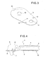
- the flat support element which forms the support device (3) for the pulley (2), not shown in this drawing, may be seen. Also shown is the opening (10) for the rivet (4) for the pulley (2) to pass through as well as the circular opening (11) for inserting the lower extension (7) of the tubular body (6).
- the circular shape of the opening (11) allows the tubular body (6) to turn of the cable stopper. Its final positioning is carried out using the holes (12) radially located on this plate (3) into one of which a pivot is located which extends from the aforementioned tubular body (6) (not shown). These holes (12) in combination with the aforementioned pivot comprise a way of angular positioning of the stopper (5).
- a positioning projection (13) may be seen which extends downwards to be inserted into one of the holes in the rail setting the position of the support device (3) for the pulley (2) on the rail; i.e the angle of departure for the window lifter cable and sheath.
- the aforementioned projection (13) is formed by bending the end of the support element (3)at the opposite end to where the opening is located (11), as it can be seen in figures 3 and 4 .
Landscapes
- Window Of Vehicle (AREA)
- Transplanting Machines (AREA)
- Seal Device For Vehicle (AREA)
Claims (6)
- Rollenvorrichtung zum Heben von Fahrzeugscheiben, bestehend aus einer umlaufenden Rolle (2), um die ein durch eine Umhüllung laufendes Antriebskabel geführt wird, und einer Haltevorrichtung, die am Ende einer Fensterhebeschiene befestigbar ist, wobei die Haltevorrichtung ein Halteelement (3), auf das die Rolle (2) montiert wird, und einen Anschlag (5) für das Ende der Kabelumhüllung umfasst, wobei das Halteelement (3) eine Öffnung (11) für die Montage des Anschlags (5) aufweist, dadurch gekennzeichnet, dass das Halteelement (3) vollkommen flach ist und ferner eine Bohrung (10) zur Befestigung der Rolle (2) mit einem Niet (4) und Mitteln (12, 13) zum Positionieren des Anschlags (5) an einer variablen Winkeleinstellung in Bezug auf das Halteelement (3) und die Fensterhebeschiene umfasst, wobei das Halteelement (3) symmetrisch zu einer Längsachse dieser Schiene verläuft.
- Rollenvorrichtung zum Heben von Fahrzeugscheiben nach Anspruch 1, dadurch gekennzeichnet, dass der Anschlag (5) einen röhrenförmigen Körper (6) umfasst, der an dem Halteelement (3) befestigt ist, und dass der röhrenförmige Körper (6) eine untere Verlängerung (7) in Form einer in die Öffnung (11) auf dem Halteelement (3) einführbaren Klammer besitzt, die einen im Wesentlichen V-förmigen Querschnitt aufweist, womit verhindert wird, dass sich der röhrenförmiger Körper (6) nach seinem Einführen in die Öffnung (11) aus dem Halteelement (3) löst.
- Rollenvorrichtung zum Heben von Fahrzeugscheiben nach Anspruch 1, dadurch gekennzeichnet, dass die Mittel zum Positionieren des Anschlags (5) an einer variablen Winkeleinstellung in Bezug auf das Halteelement (3) und die Fensterhebeschiene mehrere in dem Halteelement (3) vorhandene Bohrungen (12) aufweisen, wobei in eine davon ein von dem röhrenförmigen Körper (6) ausgehender Stift eingeführt wird.
- Rollenvorrichtung zum Heben von Fahrzeugscheiben nach Anspruch 2, dadurch gekennzeichnet, dass der röhrenförmige Körper (6) seitliche Vorsprünge (8, 9) aufweist, die sich auf dem Halteelement (3) abstützen, sobald die untere Verlängerung (7) in die Öffnung (11) desselben eingeführt wurde.
- Rollenvorrichtung zum Heben von Fahrzeugscheiben nach Anspruch 1, dadurch gekennzeichnet, dass das Halteelement (3) eine Positioniernase (13) aufweist, die sich nach unten erstreckt und für die Einführung in eine Bohrung in der Fensterhebeschiene konzipiert ist, um einen Überhangwinkel zu bilden, der verhindert, dass sich das Halteelement (3) um eine Achse der Rolle (2) dreht.
- Rollenvorrichtung zum Heben von Fahrzeugscheiben nach den obigen Ansprüchen, dadurch gekennzeichnet, dass das Halteelement (3) einen mittig angeordneten Drehkopf mit einer Bohrung aufweist, durch welche die Fensterhebeschiene bei Verwendung der Rolle (2) befestigt werden kann.
Applications Claiming Priority (2)
| Application Number | Priority Date | Filing Date | Title |
|---|---|---|---|
| ES200401377U ES1057714Y (es) | 2004-06-08 | 2004-06-08 | Dispositivo de polea para elevalunas de vehiculos. |
| PCT/ES2005/000062 WO2006000597A1 (es) | 2004-06-08 | 2005-02-09 | Dispositivo de polea para elevalunas de vehículos |
Publications (2)
| Publication Number | Publication Date |
|---|---|
| EP1754853A1 EP1754853A1 (de) | 2007-02-21 |
| EP1754853B1 true EP1754853B1 (de) | 2008-10-15 |
Family
ID=32922014
Family Applications (1)
| Application Number | Title | Priority Date | Filing Date |
|---|---|---|---|
| EP05701713A Expired - Lifetime EP1754853B1 (de) | 2004-06-08 | 2005-02-09 | Riemenscheibenvorrichtung für fahrzeugfensterheber |
Country Status (7)
| Country | Link |
|---|---|
| US (1) | US20070289218A1 (de) |
| EP (1) | EP1754853B1 (de) |
| AT (1) | ATE411442T1 (de) |
| AU (1) | AU2005256102B2 (de) |
| DE (1) | DE602005010427D1 (de) |
| ES (1) | ES1057714Y (de) |
| WO (1) | WO2006000597A1 (de) |
Families Citing this family (6)
| Publication number | Priority date | Publication date | Assignee | Title |
|---|---|---|---|---|
| ES1065709Y (es) * | 2007-06-14 | 2008-01-16 | Castellon Melchor Daumal | Soporte perfeccionado para roldana de aplicacion en perfiles guia para dispositivos elevalunas |
| JP2014020005A (ja) * | 2012-07-12 | 2014-02-03 | Shiroki Corp | ウィンドレギュレータのガイドプーリ支持構造 |
| JP6374296B2 (ja) * | 2014-10-31 | 2018-08-15 | 株式会社ハイレックスコーポレーション | ガイドレール嵌合構造及びウィンドウレギュレータ |
| JP6225141B2 (ja) * | 2015-05-29 | 2017-11-01 | シロキ工業株式会社 | ウインドレギュレータ |
| FR3041676B1 (fr) * | 2015-09-24 | 2019-07-19 | Inteva Products France Sas | Appareil et procédé pour un renfort de poulie dans un leve vitre |
| DE102022121891A1 (de) * | 2021-09-01 | 2023-03-02 | Magna Closures Inc. | Seilscheiben-verbindungshalter für fensterhebersystemfeld |
Family Cites Families (16)
| Publication number | Priority date | Publication date | Assignee | Title |
|---|---|---|---|---|
| DE3118311C2 (de) * | 1981-05-08 | 1984-04-05 | Brose Fahrzeugteile GmbH & Co KG, 8630 Coburg | Seil-Fensterheber, insbesondere für Kraftfahrzeuge |
| DE8230460U1 (de) * | 1982-10-29 | 1983-03-17 | Brose Fahrzeugteile GmbH & Co KG, 8630 Coburg | Kraftfahrzeugfensterheber |
| EP0164116B1 (de) * | 1984-06-06 | 1989-09-06 | Toyota Jidosha Kabushiki Kaisha | Tür-Fensterheber |
| GB2168106B (en) * | 1984-12-06 | 1987-10-14 | Weston Hydraulics Ltd | Joint for orthotic device |
| JPS62125184A (ja) * | 1985-11-07 | 1987-06-06 | 株式会社 大井製作所 | ワイヤ駆動式ウインドレギユレ−タにおけるワイヤの張着方法 |
| JPH03209042A (ja) * | 1990-01-08 | 1991-09-12 | Koito Mfg Co Ltd | 昇降装置 |
| JPH03228987A (ja) * | 1990-02-02 | 1991-10-09 | Koito Mfg Co Ltd | 昇降装置 |
| JPH03229887A (ja) * | 1990-02-02 | 1991-10-11 | Zero Wan:Kk | 銀合金表面の硫化物除去剤及びこれを用いた硫化物除去方法 |
| DE4131098A1 (de) * | 1991-09-16 | 1993-03-25 | Brose Fahrzeugteile | Seil-fensterheber, insbesondere fuer den einbau in kraftfahrzeugen |
| JP3416321B2 (ja) * | 1995-02-20 | 2003-06-16 | 三菱自動車工業株式会社 | ウインドウガラスレギュレータ |
| JP3421482B2 (ja) * | 1995-09-14 | 2003-06-30 | シロキ工業株式会社 | ウィンドガラス昇降機構のワイヤ支持装置 |
| DE19857872C2 (de) * | 1997-12-16 | 2003-07-17 | Asmo Co Ltd | Angetriebener Fensterheber und Fensterhebersystem |
| US7234274B2 (en) * | 2001-07-10 | 2007-06-26 | Kabushikikaisha Ansei | Vehicle door |
| US6758013B2 (en) * | 2002-01-25 | 2004-07-06 | Delphi Technologies, Inc. | Integrated roller cable assembly |
| US6910730B2 (en) * | 2002-12-25 | 2005-06-28 | Shiroki Corporation | Mounting device for mounting a cable-operated window regulator |
| US6796085B2 (en) * | 2003-01-24 | 2004-09-28 | Peter J. Smith | Window regulator |
-
2004
- 2004-06-08 ES ES200401377U patent/ES1057714Y/es not_active Expired - Fee Related
-
2005
- 2005-02-09 AT AT05701713T patent/ATE411442T1/de not_active IP Right Cessation
- 2005-02-09 DE DE602005010427T patent/DE602005010427D1/de not_active Expired - Lifetime
- 2005-02-09 EP EP05701713A patent/EP1754853B1/de not_active Expired - Lifetime
- 2005-02-09 AU AU2005256102A patent/AU2005256102B2/en not_active Ceased
- 2005-02-09 US US10/571,609 patent/US20070289218A1/en not_active Abandoned
- 2005-02-09 WO PCT/ES2005/000062 patent/WO2006000597A1/es not_active Ceased
Also Published As
| Publication number | Publication date |
|---|---|
| ES1057714Y (es) | 2004-12-16 |
| AU2005256102B2 (en) | 2010-12-23 |
| AU2005256102A1 (en) | 2006-03-02 |
| ATE411442T1 (de) | 2008-10-15 |
| ES1057714U (es) | 2004-09-01 |
| EP1754853A1 (de) | 2007-02-21 |
| AU2005256102A8 (en) | 2008-09-18 |
| DE602005010427D1 (de) | 2008-11-27 |
| US20070289218A1 (en) | 2007-12-20 |
| WO2006000597A1 (es) | 2006-01-05 |
Similar Documents
| Publication | Publication Date | Title |
|---|---|---|
| EP1754853B1 (de) | Riemenscheibenvorrichtung für fahrzeugfensterheber | |
| CN110359807B (zh) | 车窗调节器 | |
| US4759653A (en) | Wire fixing device for window regulator | |
| JP6247227B2 (ja) | 開閉体開閉装置 | |
| US4056274A (en) | Vehicle sliding roof construction | |
| EP0563742A1 (de) | Vormontierte Bedienungstafel für Fahrzeugtüren | |
| US7143621B2 (en) | Guide support for a tube-bending machine | |
| EP1020310B1 (de) | Vereinfachte fensterkurbel | |
| JP4545751B2 (ja) | 特に自動車用のアームレスト及びその方法 | |
| DE59806154D1 (de) | Vorrichtung zum Biegen eines Hohlprofiles mit einem Niederhalter | |
| DE20213813U1 (de) | Führungsschienen-Anordnung für Seilfensterheber | |
| US5339505A (en) | Band-clamping apparatus | |
| US20070094844A1 (en) | Metallic hinge motion check friction device including a one-piece design, methods incorporating the device, and uses thereof | |
| EP3960977A1 (de) | Zielobjektbewegungsvorrichtung | |
| KR102163078B1 (ko) | 자동차용 윈도우 레귤레이터의 풀리 결합구조 | |
| KR101410224B1 (ko) | 다차종 차체패널 고정을 위한 베벨기어타입 핀유닛 | |
| EP0976646B1 (de) | Verfahren und Vorrichtung zum Verbinden einer Fensterscheibe mit einem Fensterheber | |
| JP2006516311A (ja) | 偏心ローラ装置 | |
| EP1533458B1 (de) | kunststoffschienenformprofil eines kraftfahrzeugfensterhebers | |
| CN113167093A (zh) | 车窗提升系统和机动车门 | |
| DE202011051748U1 (de) | Vorrichtung zum Spannen eines Fensterheberseils | |
| JP3798646B2 (ja) | ウインドレギュレータ | |
| KR200430946Y1 (ko) | 자동차용 도어모듈패널 및 도어인너패널과의 조립구조 | |
| KR0138670B1 (ko) | 차량 전면의 대쉬판넬 조립작업용 가이드 롤러 | |
| EP1520742A1 (de) | Vorrichtung zur Seiteneinstellung einer Fensterheberantriebsvorrichtung für Kraftfahrzeuge |
Legal Events
| Date | Code | Title | Description |
|---|---|---|---|
| PUAI | Public reference made under article 153(3) epc to a published international application that has entered the european phase |
Free format text: ORIGINAL CODE: 0009012 |
|
| 17P | Request for examination filed |
Effective date: 20060120 |
|
| AK | Designated contracting states |
Kind code of ref document: A1 Designated state(s): AT BE BG CH CY CZ DE DK EE ES FI FR GB GR HU IE IS IT LI LT LU MC NL PL PT RO SE SI SK TR |
|
| 17Q | First examination report despatched |
Effective date: 20070709 |
|
| DAX | Request for extension of the european patent (deleted) | ||
| GRAP | Despatch of communication of intention to grant a patent |
Free format text: ORIGINAL CODE: EPIDOSNIGR1 |
|
| GRAS | Grant fee paid |
Free format text: ORIGINAL CODE: EPIDOSNIGR3 |
|
| GRAA | (expected) grant |
Free format text: ORIGINAL CODE: 0009210 |
|
| AK | Designated contracting states |
Kind code of ref document: B1 Designated state(s): AT BE BG CH CY CZ DE DK EE ES FI FR GB GR HU IE IS IT LI LT LU MC NL PL PT RO SE SI SK TR |
|
| REG | Reference to a national code |
Ref country code: GB Ref legal event code: FG4D Ref country code: CH Ref legal event code: EP |
|
| REG | Reference to a national code |
Ref country code: IE Ref legal event code: FG4D |
|
| REF | Corresponds to: |
Ref document number: 602005010427 Country of ref document: DE Date of ref document: 20081127 Kind code of ref document: P |
|
| NLV1 | Nl: lapsed or annulled due to failure to fulfill the requirements of art. 29p and 29m of the patents act | ||
| PG25 | Lapsed in a contracting state [announced via postgrant information from national office to epo] |
Ref country code: AT Free format text: LAPSE BECAUSE OF FAILURE TO SUBMIT A TRANSLATION OF THE DESCRIPTION OR TO PAY THE FEE WITHIN THE PRESCRIBED TIME-LIMIT Effective date: 20081015 Ref country code: LT Free format text: LAPSE BECAUSE OF FAILURE TO SUBMIT A TRANSLATION OF THE DESCRIPTION OR TO PAY THE FEE WITHIN THE PRESCRIBED TIME-LIMIT Effective date: 20081015 Ref country code: ES Free format text: LAPSE BECAUSE OF FAILURE TO SUBMIT A TRANSLATION OF THE DESCRIPTION OR TO PAY THE FEE WITHIN THE PRESCRIBED TIME-LIMIT Effective date: 20090126 Ref country code: BG Free format text: LAPSE BECAUSE OF FAILURE TO SUBMIT A TRANSLATION OF THE DESCRIPTION OR TO PAY THE FEE WITHIN THE PRESCRIBED TIME-LIMIT Effective date: 20090115 |
|
| PG25 | Lapsed in a contracting state [announced via postgrant information from national office to epo] |
Ref country code: FI Free format text: LAPSE BECAUSE OF FAILURE TO SUBMIT A TRANSLATION OF THE DESCRIPTION OR TO PAY THE FEE WITHIN THE PRESCRIBED TIME-LIMIT Effective date: 20081015 Ref country code: PT Free format text: LAPSE BECAUSE OF FAILURE TO SUBMIT A TRANSLATION OF THE DESCRIPTION OR TO PAY THE FEE WITHIN THE PRESCRIBED TIME-LIMIT Effective date: 20090316 Ref country code: NL Free format text: LAPSE BECAUSE OF FAILURE TO SUBMIT A TRANSLATION OF THE DESCRIPTION OR TO PAY THE FEE WITHIN THE PRESCRIBED TIME-LIMIT Effective date: 20081015 Ref country code: SI Free format text: LAPSE BECAUSE OF FAILURE TO SUBMIT A TRANSLATION OF THE DESCRIPTION OR TO PAY THE FEE WITHIN THE PRESCRIBED TIME-LIMIT Effective date: 20081015 Ref country code: PL Free format text: LAPSE BECAUSE OF FAILURE TO SUBMIT A TRANSLATION OF THE DESCRIPTION OR TO PAY THE FEE WITHIN THE PRESCRIBED TIME-LIMIT Effective date: 20081015 Ref country code: IS Free format text: LAPSE BECAUSE OF FAILURE TO SUBMIT A TRANSLATION OF THE DESCRIPTION OR TO PAY THE FEE WITHIN THE PRESCRIBED TIME-LIMIT Effective date: 20090215 |
|
| PG25 | Lapsed in a contracting state [announced via postgrant information from national office to epo] |
Ref country code: EE Free format text: LAPSE BECAUSE OF FAILURE TO SUBMIT A TRANSLATION OF THE DESCRIPTION OR TO PAY THE FEE WITHIN THE PRESCRIBED TIME-LIMIT Effective date: 20081015 Ref country code: DK Free format text: LAPSE BECAUSE OF FAILURE TO SUBMIT A TRANSLATION OF THE DESCRIPTION OR TO PAY THE FEE WITHIN THE PRESCRIBED TIME-LIMIT Effective date: 20081015 Ref country code: RO Free format text: LAPSE BECAUSE OF FAILURE TO SUBMIT A TRANSLATION OF THE DESCRIPTION OR TO PAY THE FEE WITHIN THE PRESCRIBED TIME-LIMIT Effective date: 20081015 Ref country code: BE Free format text: LAPSE BECAUSE OF FAILURE TO SUBMIT A TRANSLATION OF THE DESCRIPTION OR TO PAY THE FEE WITHIN THE PRESCRIBED TIME-LIMIT Effective date: 20081015 |
|
| PLBE | No opposition filed within time limit |
Free format text: ORIGINAL CODE: 0009261 |
|
| STAA | Information on the status of an ep patent application or granted ep patent |
Free format text: STATUS: NO OPPOSITION FILED WITHIN TIME LIMIT |
|
| PG25 | Lapsed in a contracting state [announced via postgrant information from national office to epo] |
Ref country code: CZ Free format text: LAPSE BECAUSE OF FAILURE TO SUBMIT A TRANSLATION OF THE DESCRIPTION OR TO PAY THE FEE WITHIN THE PRESCRIBED TIME-LIMIT Effective date: 20081015 Ref country code: SE Free format text: LAPSE BECAUSE OF FAILURE TO SUBMIT A TRANSLATION OF THE DESCRIPTION OR TO PAY THE FEE WITHIN THE PRESCRIBED TIME-LIMIT Effective date: 20090115 |
|
| 26N | No opposition filed |
Effective date: 20090716 |
|
| PG25 | Lapsed in a contracting state [announced via postgrant information from national office to epo] |
Ref country code: SK Free format text: LAPSE BECAUSE OF FAILURE TO SUBMIT A TRANSLATION OF THE DESCRIPTION OR TO PAY THE FEE WITHIN THE PRESCRIBED TIME-LIMIT Effective date: 20081015 Ref country code: MC Free format text: LAPSE BECAUSE OF NON-PAYMENT OF DUE FEES Effective date: 20090228 |
|
| REG | Reference to a national code |
Ref country code: CH Ref legal event code: PL |
|
| PG25 | Lapsed in a contracting state [announced via postgrant information from national office to epo] |
Ref country code: LI Free format text: LAPSE BECAUSE OF NON-PAYMENT OF DUE FEES Effective date: 20090228 Ref country code: CH Free format text: LAPSE BECAUSE OF NON-PAYMENT OF DUE FEES Effective date: 20090228 |
|
| REG | Reference to a national code |
Ref country code: IE Ref legal event code: MM4A |
|
| PG25 | Lapsed in a contracting state [announced via postgrant information from national office to epo] |
Ref country code: IE Free format text: LAPSE BECAUSE OF NON-PAYMENT OF DUE FEES Effective date: 20090209 |
|
| PG25 | Lapsed in a contracting state [announced via postgrant information from national office to epo] |
Ref country code: GR Free format text: LAPSE BECAUSE OF FAILURE TO SUBMIT A TRANSLATION OF THE DESCRIPTION OR TO PAY THE FEE WITHIN THE PRESCRIBED TIME-LIMIT Effective date: 20090116 |
|
| PG25 | Lapsed in a contracting state [announced via postgrant information from national office to epo] |
Ref country code: LU Free format text: LAPSE BECAUSE OF NON-PAYMENT OF DUE FEES Effective date: 20090209 |
|
| PGFP | Annual fee paid to national office [announced via postgrant information from national office to epo] |
Ref country code: DE Payment date: 20110228 Year of fee payment: 7 Ref country code: FR Payment date: 20110214 Year of fee payment: 7 Ref country code: IT Payment date: 20110228 Year of fee payment: 7 |
|
| PG25 | Lapsed in a contracting state [announced via postgrant information from national office to epo] |
Ref country code: HU Free format text: LAPSE BECAUSE OF FAILURE TO SUBMIT A TRANSLATION OF THE DESCRIPTION OR TO PAY THE FEE WITHIN THE PRESCRIBED TIME-LIMIT Effective date: 20090416 |
|
| PGFP | Annual fee paid to national office [announced via postgrant information from national office to epo] |
Ref country code: GB Payment date: 20110125 Year of fee payment: 7 |
|
| PG25 | Lapsed in a contracting state [announced via postgrant information from national office to epo] |
Ref country code: TR Free format text: LAPSE BECAUSE OF FAILURE TO SUBMIT A TRANSLATION OF THE DESCRIPTION OR TO PAY THE FEE WITHIN THE PRESCRIBED TIME-LIMIT Effective date: 20081015 |
|
| PG25 | Lapsed in a contracting state [announced via postgrant information from national office to epo] |
Ref country code: CY Free format text: LAPSE BECAUSE OF FAILURE TO SUBMIT A TRANSLATION OF THE DESCRIPTION OR TO PAY THE FEE WITHIN THE PRESCRIBED TIME-LIMIT Effective date: 20081015 |
|
| GBPC | Gb: european patent ceased through non-payment of renewal fee |
Effective date: 20120209 |
|
| REG | Reference to a national code |
Ref country code: FR Ref legal event code: ST Effective date: 20121031 |
|
| PG25 | Lapsed in a contracting state [announced via postgrant information from national office to epo] |
Ref country code: IT Free format text: LAPSE BECAUSE OF NON-PAYMENT OF DUE FEES Effective date: 20120209 |
|
| REG | Reference to a national code |
Ref country code: DE Ref legal event code: R119 Ref document number: 602005010427 Country of ref document: DE Effective date: 20120901 |
|
| PG25 | Lapsed in a contracting state [announced via postgrant information from national office to epo] |
Ref country code: GB Free format text: LAPSE BECAUSE OF NON-PAYMENT OF DUE FEES Effective date: 20120209 Ref country code: FR Free format text: LAPSE BECAUSE OF NON-PAYMENT OF DUE FEES Effective date: 20120229 |
|
| PG25 | Lapsed in a contracting state [announced via postgrant information from national office to epo] |
Ref country code: DE Free format text: LAPSE BECAUSE OF NON-PAYMENT OF DUE FEES Effective date: 20120901 |