EP1754567B1 - Werkzeugmaschine mit Faltenbalgabdeckung - Google Patents
Werkzeugmaschine mit Faltenbalgabdeckung Download PDFInfo
- Publication number
- EP1754567B1 EP1754567B1 EP05018050A EP05018050A EP1754567B1 EP 1754567 B1 EP1754567 B1 EP 1754567B1 EP 05018050 A EP05018050 A EP 05018050A EP 05018050 A EP05018050 A EP 05018050A EP 1754567 B1 EP1754567 B1 EP 1754567B1
- Authority
- EP
- European Patent Office
- Prior art keywords
- machine tool
- bellows
- cabin
- concertina
- slide
- Prior art date
- Legal status (The legal status is an assumption and is not a legal conclusion. Google has not performed a legal analysis and makes no representation as to the accuracy of the status listed.)
- Revoked
Links
- 238000003754 machining Methods 0.000 description 2
- 230000001960 triggered effect Effects 0.000 description 1
Images


Classifications
-
- B—PERFORMING OPERATIONS; TRANSPORTING
- B23—MACHINE TOOLS; METAL-WORKING NOT OTHERWISE PROVIDED FOR
- B23Q—DETAILS, COMPONENTS, OR ACCESSORIES FOR MACHINE TOOLS, e.g. ARRANGEMENTS FOR COPYING OR CONTROLLING; MACHINE TOOLS IN GENERAL CHARACTERISED BY THE CONSTRUCTION OF PARTICULAR DETAILS OR COMPONENTS; COMBINATIONS OR ASSOCIATIONS OF METAL-WORKING MACHINES, NOT DIRECTED TO A PARTICULAR RESULT
- B23Q11/00—Accessories fitted to machine tools for keeping tools or parts of the machine in good working condition or for cooling work; Safety devices specially combined with or arranged in, or specially adapted for use in connection with, machine tools
- B23Q11/08—Protective coverings for parts of machine tools; Splash guards
- B23Q11/0816—Foldable coverings, e.g. bellows
-
- Y—GENERAL TAGGING OF NEW TECHNOLOGICAL DEVELOPMENTS; GENERAL TAGGING OF CROSS-SECTIONAL TECHNOLOGIES SPANNING OVER SEVERAL SECTIONS OF THE IPC; TECHNICAL SUBJECTS COVERED BY FORMER USPC CROSS-REFERENCE ART COLLECTIONS [XRACs] AND DIGESTS
- Y10—TECHNICAL SUBJECTS COVERED BY FORMER USPC
- Y10T—TECHNICAL SUBJECTS COVERED BY FORMER US CLASSIFICATION
- Y10T409/00—Gear cutting, milling, or planing
- Y10T409/30—Milling
- Y10T409/30392—Milling with means to protect operative or machine [e.g., guard, safety device, etc.]
-
- Y—GENERAL TAGGING OF NEW TECHNOLOGICAL DEVELOPMENTS; GENERAL TAGGING OF CROSS-SECTIONAL TECHNOLOGIES SPANNING OVER SEVERAL SECTIONS OF THE IPC; TECHNICAL SUBJECTS COVERED BY FORMER USPC CROSS-REFERENCE ART COLLECTIONS [XRACs] AND DIGESTS
- Y10—TECHNICAL SUBJECTS COVERED BY FORMER USPC
- Y10T—TECHNICAL SUBJECTS COVERED BY FORMER US CLASSIFICATION
- Y10T409/00—Gear cutting, milling, or planing
- Y10T409/30—Milling
- Y10T409/30784—Milling including means to adustably position cutter
- Y10T409/307952—Linear adjustment
- Y10T409/308288—Linear adjustment including gantry-type cutter-carrier
-
- Y—GENERAL TAGGING OF NEW TECHNOLOGICAL DEVELOPMENTS; GENERAL TAGGING OF CROSS-SECTIONAL TECHNOLOGIES SPANNING OVER SEVERAL SECTIONS OF THE IPC; TECHNICAL SUBJECTS COVERED BY FORMER USPC CROSS-REFERENCE ART COLLECTIONS [XRACs] AND DIGESTS
- Y10—TECHNICAL SUBJECTS COVERED BY FORMER USPC
- Y10T—TECHNICAL SUBJECTS COVERED BY FORMER US CLASSIFICATION
- Y10T74/00—Machine element or mechanism
- Y10T74/21—Elements
- Y10T74/2193—Guard mechanisms
Definitions
- the invention relates to a machine tool according to the preamble of claim 1.
- a machine tool with bellows is out of the EP 1 146 994 B1 known.
- the machine tool comprises a closed by walls and a roof cover working space in which a device for receiving a workpiece and a headstock are arranged with a main spindle into which tools for machining the workpiece are clamped.
- Device and headstock are movable relative to each other.
- a closable by a door opening is provided which leads into the working space.
- At least a portion of the roof cover is movable between two positions such that it closes the working space in a first position upwards and releases in a second position for loading upwards.
- the object of the present invention is in particular to propose a roof cover of a machine tool which can be actuated without separate drive in a simple and fast manner, which provides the largest possible space for loading and unloading of tools and / or workpieces when opening the roof of the machine and when the roof of the machine tool is closed during operation of the machine tool supplies the required degree to the outside.
- the bellows is detachably connectable to the longitudinal side of the carriage and / or the cabin.
- the bellows can be connected to the longitudinal side of the carriage and / or to the cabin to deploy the bellows, fauxzuücken or transport.
- guide elements cooperating with one another are preferably provided on the side walls and on the bellows.
- the bellows and / or the carriage and / or to the longitudinal side of the cabin cooperating connecting means for example electromagnetic or mechanical means on.
- connection means for the bellows with the carriage and / or with the longitudinal side of the cabin are preferably triggered by a remote control.
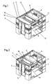
- FIGS. 1 to 4 a cab 5 of a machine tool is shown.
- the car 5 is cuboid shaped with the side walls 1 and 2 and the front and rear wall with the doors 3 and 4.
- a carriage 6 is guided on side rails 11.
- the carriage 6 serves to receive a spindle head, not shown in the drawing, with a tool for machining a workpiece, which likewise is not shown in the drawing.
- the roof surface 12 of the cab 5 is in FIG. 1 Partially covered by a bellows 7 in the front area.
- the bellows 7 can be connected at its longitudinal side 13 with the front longitudinal side 14 of the carriage 6 by connecting means 10, for example, electromagnetically, by pawls, etc.
- the magnets or the pawls are operated by a console, not shown.
- the bellows 7 In the latched state, the bellows 7 is collapsible and transportable as it FIGS. 2 to 4 demonstrate.
- FIG. 2 the bellows 7 is folded and located at the top of the door side 3 of the cabin 5.
- FIG. 3 the bellows 7 was transported in the central region of the roof surface, wherein the bellows 7 is guided on the rails 16. With the door open 3 open, thus a large space for loading and unloading of parts is formed.
- FIG. 4 is again the state of the folded bellows 7 on the door side 3 of the cab 5 to see.
- connection means 10 may be electromagnetic devices or mechanical devices, such as pawls. These connecting means 10 can be operated by a control panel on or outside the machine. Furthermore, 7 guide elements 9 for guiding the bellows 7 in the rails 16 of the cab 5 are provided on the side surfaces of the bellows.
Landscapes
- Engineering & Computer Science (AREA)
- Mechanical Engineering (AREA)
- Auxiliary Devices For Machine Tools (AREA)
- Operating, Guiding And Securing Of Roll- Type Closing Members (AREA)
- Diaphragms And Bellows (AREA)
Description
- Die Erfindung betrifft eine Werkzeugmaschine nach dem Oberbegriff von Anspruch 1.
- Eine Werkzeugmaschine mit Faltenbalg ist aus der
EP 1 146 994 B1 bekannt. Die Werkzeugmaschine umfasst einen durch Wände sowie eine Dachabdeckung abgeschlossenen Arbeitsraum, in dem eine Vorrichtung zur Aufnahme eines Werkstückes sowie ein Spindelstock mit einer Hauptspindel angeordnet sind, in die Werkzeuge zur Bearbeitung des Werkstückes einspannbar sind. Vorrichtung und Spindelstock sind relativ zueinander verfahrbar. In einer vorderen Wand ist eine durch eine Tür verschliessbare Öffnung vorgesehen, die in den Arbeitsraum führt. Zumindest ein Teil der Dachabdeckung ist zwischen zwei Stellungen derart verfahrbar, dass er in einer ersten Stellung den Arbeitsraum nach oben abschliesst und in einer zweiten Stellung zum Beladen nach oben freigibt. - Die Aufgabe der vorliegenden Erfindung liegt insbesondere darin, eine Dachabdeckung einer Werkzeugmaschine vorzuschlagen, die ohne separatem Antrieb in einfacher und schneller Weise betätigbar ist, die bei Öffnung des Daches der Maschine einen möglichst grossen Freiraum zur Be- und Entladung von Werkzeugen und/oder Werkstücken liefert und die bei geschlossenem Dach der Werkzeugmaschine im Betrieb der Werkzeugmaschine den erforderlichen Abschluss nach aussen liefert.
- Erfindungsgemäss wird die Aufgabe durch das Kennzeichen von Anspruch 1 gelöst.
- Dies hat zum Vorteil, dass für die Betätigung des Faltenbalgs kein spezieller Antrieb benötigt wird. Der Faltenbalg wird mittels der Schlittenbewegung mitgenommen entfaltet oder zusammengefaltet.
- In vorteilhafter Weise ist der Faltenbalg lösbar mit der Längsseite zum Schlitten und/oder zur Kabine verbindbar. Je nach Anforderung kann der Faltenbalg mit der Längsseite zum Schlitten und/oder zur Kabine verbunden werden, um den Faltenbalg zu entfalten, zusammenzurücken oder zu transportieren.
- Um den Faltenbalg verschiebbar zu transportieren sind bevorzugt an den Seitenwänden und am Faltenbalg zusammenwirkende Führungselementen vorgesehen.
- Gemäss einer weiteren bevorzugten Ausführungsform weist der Faltenbalg und/oder der Schlitten und/oder zur Längsseite der Kabine zusammenwirkende Verbindungsmittel, beispielsweise elektromagnetische oder mechanische Mittel, auf.
- Die Verbindungsmittel für den Faltenbalg mit dem Schlitten und/oder mit der Längsseite der Kabine sind bevorzugt durch eine Fernbetätigung auslösbar.
- Ein Ausführungsbeispiel ist in der Zeichnung dargestellt und wird im folgenden beschrieben. Es zeigen:
- Fig. 1
- eine Maschinenkabine mit teilweise entfaltetem Faltenbalg
- Fig. 2
- eine Maschinenkabine mit zusammengefaltetem Faltenbalg
- Fig. 3
- eine Maschinenkabine mit in die Mitte geschobenen Faltenbalg
- Fig. 4
- eine Maschinenkabine mit zusammengefaltetem Faltenbalg
- Fig. 5
- eine dreidimensionale Ansicht des Faltenbalges
- Fig. 6
- eine Draufsicht des Faltenbalges
- In den
Figuren 1 bis 4 ist eine Kabine 5 einer Werkzeugmaschine gezeigt. Die Kabine 5 ist quaderförmig gestaltet mit den Seitenwänden 1 und 2 und der vordere und rückseitigen Wand mit den Türen 3 und 4. Ein Schlitten 6 ist auf seitlichen Schienen 11 geführt. Der Schlitten 6 dient zur Aufnahme eines in der Zeichnung nicht dargestellten Spindelkopfes mit Werkzeug für die Bearbeitung eines Werkstückes, welches ebenfalls nicht in der Zeichnung gezeigt ist. Die Dachfläche 12 der Kabine 5 ist inFigur 1 mittels eine Faltenbalges 7 im vorderen Bereich teilweise abgedeckt. Der Faltenbalg 7 kann an seiner Längsseite 13 mit der vorderen Längsseite 14 des Schlittens 6 durch Verbindungsmittel 10 verbunden werden, beispielsweise elektromagnetisch, durch Klinken etc. Die Magnete oder die Klinken sind von einer nicht dargestellten Konsole bedienbar. Im eingeklinkten Zustand ist der Faltenbalg 7 zusammenfaltbar und transportierbar wie es dieFiguren 2 bis 4 zeigen. InFigur 2 ist der Faltenbalg 7 zusammengefaltet und befindet sich am oberen Rand der Türseite 3 der Kabine 5. InFigur 3 wurde der Faltenbalg 7 in den mittleren Bereich der Dachfläche transportiert, wobei der Faltenbalg 7 auf den Schienen 16 geführt ist. Bei geöffneter holmenfreier Tür 3 wird somit ein grosser Freiraum zur Be- und Entladung von Teilen gebildet. InFigur 4 ist nochmals der Zustand des zusammengefalteten Faltenbalges 7 an der Türseite 3 der Kabine 5 zu sehen. - In den
Figuren 5 und 6 ist der Faltenbalg 7 dargestellt. Der eigentliche faltbare Balg 17 ist mittels einer Traverse 18 eingefasst. In der Mitte und an den Seiten der Traverse 18 sind Verbindungsmittel 10 vorgesehen. Diese Verbindungsmittel 10 können elektromagnetische Einrichtungen oder mechanische Einrichtungen sein, beispielsweise Klinken. Diese Verbindungsmittel 10 sind von einem Bedienpult an oder ausserhalb der Maschine bedienbar. Weiterhin sind an den Seitenflächen des Faltenbalges 7 Führungselemente 9 zur Führung des Faltenbalges 7 in den Schienen 16 der Kabine 5 vorgesehen. - Die mit der Erfindung verbundenen Vorteile bestehen insbesondere darin, dass der ohne separaten Antrieb betätigbare Faltenbalg einen grossen Freiraum zur Be- und Entladung des Bearbeitungsraumes ermöglicht. Besonders vorteilhaft ist die erfindungsgemässe Abdeckung dafür, dass der Maschinenraum für die Beladung schwerer und voluminöser Teile mittels Kran geeignet ist
-
- 1
- Seitenwand
- 2
- Seitenwand
- 3
- Tür
- 4
- Tür
- 5
- Kabine
- 6
- Schlitten
- 7
- Faltenbalg
- 8
- Nicht vorhanden
- 9
- Führungselemente
- 10
- Verbindungsmittel
- 11
- Schienen von 6
- 12
- Dachfläche
- 13
- Längsseite von 7
- 14
- Längsseite von 6
- 16
- Schienen von 7
- 17
- Balg
- 18
- Traverse
Claims (5)
- Werkzeugmaschine mit einer mit Seitenwänden (1, 2) und Türen (3, 4) versehenen Kabine (5), einem Schlitten (6) zur Aufnahme eines Spindelstocks, in dem Werkzeuge eingespannt sind und mit einem als Dachabdeckung dienenden Faltenbalg (7), wobei der Faltenbalg (7) mittels des Schlittens (6) parallel zur Längsseite (14) des Schlittens (6) und senkrecht zu den Seitenwänden (1, 2) entfaltbar bzw.zusammenfaltbar ist, dadurch gekennzeichnet, dass der Faltenbalg lösbar mit der Kabine (5) ist und mittels des Schlittens in Richtung der Schlittenbewegung transportierbar ist.
- Werkzeugmaschine nach Anspruch 1, dadurch gekennzeichnet, dass der Faltenbalg (7) lösbar mit der Längsseite (13) zum Schlitten (6) und/oder zur Kabine (5) verbindbar ist.
- Werkzeugmaschine nach den Ansprüchen 1 oder 2, dadurch gekennzeichnet, dass der Faltenbalg (7) mittels Führungselementen (9) am Faltenbalg (7) und an den Seitenwänden (1, 2) verschiebbar ist.
- Werkzeugmaschine nach den Ansprüchen 1, 2 oder 3, dadurch gekennzeichnet, dass der Faltenbalg (7) und/oder der Schlitten (6) zusammen wirkende Verbindungsmittel (10) aufweist.
- Werkzeugmaschine nach einem der vorherigen Ansprüche, dadurch gekennzeichnet, dass die Verbindung des Faltbalges (7) mit dem Schlitten (6) durch eine Fernbetätigung auslösbar ist.
Priority Applications (6)
| Application Number | Priority Date | Filing Date | Title |
|---|---|---|---|
| AT05018050T ATE394194T1 (de) | 2005-08-19 | 2005-08-19 | Werkzeugmaschine mit faltenbalgabdeckung |
| EP05018050A EP1754567B1 (de) | 2005-08-19 | 2005-08-19 | Werkzeugmaschine mit Faltenbalgabdeckung |
| DE502005004017T DE502005004017D1 (de) | 2005-08-19 | 2005-08-19 | Werkzeugmaschine mit Faltenbalgabdeckung |
| US11/502,015 US7261501B2 (en) | 2005-08-19 | 2006-08-10 | Machine tool with concertina cover |
| JP2006223554A JP2007050507A (ja) | 2005-08-19 | 2006-08-18 | 伸縮カバーを備える工作機械 |
| CN2006101110610A CN1915589B (zh) | 2005-08-19 | 2006-08-18 | 具有手风琴式盖的机床 |
Applications Claiming Priority (1)
| Application Number | Priority Date | Filing Date | Title |
|---|---|---|---|
| EP05018050A EP1754567B1 (de) | 2005-08-19 | 2005-08-19 | Werkzeugmaschine mit Faltenbalgabdeckung |
Publications (2)
| Publication Number | Publication Date |
|---|---|
| EP1754567A1 EP1754567A1 (de) | 2007-02-21 |
| EP1754567B1 true EP1754567B1 (de) | 2008-05-07 |
Family
ID=35447639
Family Applications (1)
| Application Number | Title | Priority Date | Filing Date |
|---|---|---|---|
| EP05018050A Revoked EP1754567B1 (de) | 2005-08-19 | 2005-08-19 | Werkzeugmaschine mit Faltenbalgabdeckung |
Country Status (6)
| Country | Link |
|---|---|
| US (1) | US7261501B2 (de) |
| EP (1) | EP1754567B1 (de) |
| JP (1) | JP2007050507A (de) |
| CN (1) | CN1915589B (de) |
| AT (1) | ATE394194T1 (de) |
| DE (1) | DE502005004017D1 (de) |
Cited By (1)
| Publication number | Priority date | Publication date | Assignee | Title |
|---|---|---|---|---|
| TWI481467B (de) * | 2012-12-26 | 2015-04-21 |
Families Citing this family (16)
| Publication number | Priority date | Publication date | Assignee | Title |
|---|---|---|---|---|
| ES2323986T3 (es) * | 2006-09-18 | 2009-07-28 | CHIRON-WERKE GMBH & CO. KG | Maquina herramienta dotada de espacio de trabajo. |
| US7412759B1 (en) * | 2007-04-24 | 2008-08-19 | Hardinge Taiwan Precision Machine Ltd. | Telescopic safety shield for machine tool |
| EP2796239A4 (de) * | 2011-12-22 | 2015-07-29 | Murata Machinery Ltd | Bearbeitungseinrichtung |
| DE202014100698U1 (de) * | 2014-02-17 | 2014-05-21 | Arno Arnold Gmbh | Maschinenabdeckung |
| CN104175173A (zh) * | 2014-09-03 | 2014-12-03 | 佛山市普拉迪数控科技有限公司 | 一种工作区域防屑系统 |
| CN105328504A (zh) * | 2015-11-11 | 2016-02-17 | 陈美青 | 雕铣机的防尘降噪结构 |
| CN106425673A (zh) * | 2016-11-16 | 2017-02-22 | 大连三垒机器股份有限公司 | 倒立式伸缩铠甲防护 |
| IT201700035667A1 (it) * | 2017-03-31 | 2018-10-01 | Parpas S P A | Macchina utensile a controllo numerico |
| JP6830035B2 (ja) * | 2017-05-22 | 2021-02-17 | オークマ株式会社 | 工作機械およびその天井カバー機構 |
| DE202019105099U1 (de) | 2019-09-13 | 2021-01-15 | Möller Werke GmbH | Abdeckvorrichtung für eine Maschinenkabine |
| CN111002095A (zh) * | 2019-12-19 | 2020-04-14 | 苏州东昱精机有限公司 | 一种天井自动门装置 |
| CN113245897B (zh) * | 2021-06-23 | 2021-12-31 | 沈阳马卡智工科技有限公司 | 一种用于五轴加工中心的护顶吸合装置及其方法 |
| CN115256037B (zh) * | 2022-09-28 | 2023-05-16 | 山东豪迈数控机床有限公司 | 机床防护安装装置及机床 |
| IT202300002952A1 (it) * | 2023-02-21 | 2024-08-21 | Jobs Spa | Macchina per la lavorazione di un pezzo meccanico |
| CN117492194B (zh) * | 2023-12-29 | 2024-03-29 | 中国航天三江集团有限公司 | 大尺寸、折叠式防护罩 |
| CN120395516A (zh) * | 2025-06-28 | 2025-08-01 | 浙江海德曼智能装备股份有限公司 | 一种机床天窗结构 |
Family Cites Families (12)
| Publication number | Priority date | Publication date | Assignee | Title |
|---|---|---|---|---|
| US3824890A (en) * | 1971-01-22 | 1974-07-23 | Giddings & Lewis | Chip guard for machine tools |
| DE3411394A1 (de) * | 1984-03-28 | 1985-10-10 | HCR-Heinrich Cremer GmbH, 4050 Mönchengladbach | Gehaeuse zur aufnahme einer werkzeugmaschine |
| DE3613520A1 (de) * | 1986-04-22 | 1987-10-29 | Stama Maschinenfabrik Gmbh | Werkzeugmaschine zum spanabhebenden bearbeiten von werkstuecken |
| DE4117699A1 (de) * | 1991-05-30 | 1992-12-03 | Stama Maschinenfabrik Gmbh | Werkzeugmaschine mit feststehendem arbeitstisch und vertikaler arbeitsspindel |
| JP3626376B2 (ja) * | 1999-09-27 | 2005-03-09 | 株式会社牧野フライス製作所 | 立形マシニングセンタ |
| DE19956900B4 (de) | 1999-11-26 | 2005-09-08 | Stama Maschinenfabrik Gmbh | Werkzeugmaschine mit Faltenbalg-Dachabdeckung |
| US6457918B1 (en) * | 2000-08-22 | 2002-10-01 | Ann Arbor Machine Company | Machining cell with debris shields |
| JP2002137143A (ja) * | 2000-10-27 | 2002-05-14 | Enshu Ltd | 工作機械の加工エリアカバー装置 |
| JP4701666B2 (ja) * | 2004-09-30 | 2011-06-15 | ブラザー工業株式会社 | 工作機械 |
| US7357769B2 (en) * | 2005-05-25 | 2008-04-15 | Mori Seiki Co., Ltd. | Machine tool |
| JP2006326803A (ja) * | 2005-05-30 | 2006-12-07 | Mori Seiki Co Ltd | 工作機械 |
| EP1754568A1 (de) * | 2005-08-19 | 2007-02-21 | Mikron Agie Charmilles AG | Werkzeugmaschine mit automatischer Abdeckung im Dachbereich |
-
2005
- 2005-08-19 EP EP05018050A patent/EP1754567B1/de not_active Revoked
- 2005-08-19 DE DE502005004017T patent/DE502005004017D1/de not_active Expired - Lifetime
- 2005-08-19 AT AT05018050T patent/ATE394194T1/de not_active IP Right Cessation
-
2006
- 2006-08-10 US US11/502,015 patent/US7261501B2/en not_active Expired - Fee Related
- 2006-08-18 JP JP2006223554A patent/JP2007050507A/ja not_active Withdrawn
- 2006-08-18 CN CN2006101110610A patent/CN1915589B/zh not_active Expired - Fee Related
Cited By (1)
| Publication number | Priority date | Publication date | Assignee | Title |
|---|---|---|---|---|
| TWI481467B (de) * | 2012-12-26 | 2015-04-21 |
Also Published As
| Publication number | Publication date |
|---|---|
| ATE394194T1 (de) | 2008-05-15 |
| EP1754567A1 (de) | 2007-02-21 |
| JP2007050507A (ja) | 2007-03-01 |
| US20070041802A1 (en) | 2007-02-22 |
| DE502005004017D1 (de) | 2008-06-19 |
| CN1915589B (zh) | 2011-09-07 |
| US7261501B2 (en) | 2007-08-28 |
| CN1915589A (zh) | 2007-02-21 |
Similar Documents
| Publication | Publication Date | Title |
|---|---|---|
| EP1754567A1 (de) | Werkzeugmaschine mit Faltenbalgabdeckung | |
| DE19956900B4 (de) | Werkzeugmaschine mit Faltenbalg-Dachabdeckung | |
| EP0654318B1 (de) | Maschine zum Feinbearbeiten der Zahnflanken von zahnradförmigen Werkstücken mit einem innenverzahnten Werkzeug | |
| EP1754568A1 (de) | Werkzeugmaschine mit automatischer Abdeckung im Dachbereich | |
| DE2234676C2 (de) | Anordnung zum Wechseln von mit Werkzeugen bestückten Werkzeughaltern an einer Werkzeugmaschine | |
| EP2185317B1 (de) | Werkzeugmaschine mit mindestens einer schiebetüre | |
| DE2703947A1 (de) | Greifvorrichtung | |
| DE102016203084B4 (de) | Transportbox zur lösbaren Befestigung an einem Fahrzeug und Kraftfahrzeug mit einer fahrzeugseitigen Befestigungseinrichtung zur Befestigung der Transportbox | |
| AT524881B1 (de) | Greifvorrichtung mit verstellbaren Schlitten | |
| DE19516849C2 (de) | Maschinenzentrum mit Werkzeugmaschinen und einer Ladevorrichtung | |
| DE202014100698U1 (de) | Maschinenabdeckung | |
| WO2018055178A1 (de) | Verfahren und werkzeugmaschine zum bearbeiten von plattenförmigen werkstücken, insbesondere von blechen | |
| DE102018000952B4 (de) | Tür für ein Kraftfahrzeug | |
| DE102016218434A1 (de) | Bearbeitungsmaschine mit Bearbeitungsräumen sowie Verfahren | |
| AT517319B1 (de) | Biegewerkzeug für eine Biegepresse | |
| DE102010004423B4 (de) | Falzverfahren und Falzvorrichtung, insbesondere für ein Karosseriebauteil | |
| DE4002445C1 (de) | ||
| EP3302842B1 (de) | Verfahren zum verstellen eines formabschnittes eines biegewerkzeuges, biegewerkezeug mit einem solchen formabschnitt und verwendung eines solchen biegewerkzeugs | |
| DE602004000702T2 (de) | Manipulator zum Verstellen von Metallblechen auf einer Arbeitsebene einer Stanzmaschine | |
| DE10325361B4 (de) | Bearbeitungszentrum mit Arbeitsraumschutz und Verfahren zum Betrieb eines Bearbeitungszentrums | |
| DE3042716C2 (de) | Werkstückpositioniervorrichtung | |
| EP1410858B1 (de) | Presse oder Stanze | |
| DE10025354C2 (de) | Abdeckvorrichtung für eine Werkzeugmaschine | |
| DE102014019209A1 (de) | Verfahren zum Betreiben eines Roboters | |
| EP1990135A1 (de) | Werkstückspannvorrichtung |
Legal Events
| Date | Code | Title | Description |
|---|---|---|---|
| PUAI | Public reference made under article 153(3) epc to a published international application that has entered the european phase |
Free format text: ORIGINAL CODE: 0009012 |
|
| AK | Designated contracting states |
Kind code of ref document: A1 Designated state(s): AT BE BG CH CY CZ DE DK EE ES FI FR GB GR HU IE IS IT LI LT LU LV MC NL PL PT RO SE SI SK TR |
|
| AX | Request for extension of the european patent |
Extension state: AL BA HR MK YU |
|
| 17P | Request for examination filed |
Effective date: 20070515 |
|
| 17Q | First examination report despatched |
Effective date: 20070615 |
|
| AKX | Designation fees paid |
Designated state(s): AT BE BG CH CY CZ DE DK EE ES FI FR GB GR HU IE IS IT LI LT LU LV MC NL PL PT RO SE SI SK TR |
|
| GRAP | Despatch of communication of intention to grant a patent |
Free format text: ORIGINAL CODE: EPIDOSNIGR1 |
|
| GRAS | Grant fee paid |
Free format text: ORIGINAL CODE: EPIDOSNIGR3 |
|
| GRAA | (expected) grant |
Free format text: ORIGINAL CODE: 0009210 |
|
| AK | Designated contracting states |
Kind code of ref document: B1 Designated state(s): AT BE BG CH CY CZ DE DK EE ES FI FR GB GR HU IE IS IT LI LT LU LV MC NL PL PT RO SE SI SK TR |
|
| REG | Reference to a national code |
Ref country code: GB Ref legal event code: FG4D Free format text: NOT ENGLISH |
|
| REG | Reference to a national code |
Ref country code: CH Ref legal event code: EP Ref country code: CH Ref legal event code: NV Representative=s name: GEORG FISCHER AG |
|
| REG | Reference to a national code |
Ref country code: IE Ref legal event code: FG4D Free format text: LANGUAGE OF EP DOCUMENT: GERMAN |
|
| REF | Corresponds to: |
Ref document number: 502005004017 Country of ref document: DE Date of ref document: 20080619 Kind code of ref document: P |
|
| PG25 | Lapsed in a contracting state [announced via postgrant information from national office to epo] |
Ref country code: SI Free format text: LAPSE BECAUSE OF FAILURE TO SUBMIT A TRANSLATION OF THE DESCRIPTION OR TO PAY THE FEE WITHIN THE PRESCRIBED TIME-LIMIT Effective date: 20080507 |
|
| PG25 | Lapsed in a contracting state [announced via postgrant information from national office to epo] |
Ref country code: NL Free format text: LAPSE BECAUSE OF FAILURE TO SUBMIT A TRANSLATION OF THE DESCRIPTION OR TO PAY THE FEE WITHIN THE PRESCRIBED TIME-LIMIT Effective date: 20080507 Ref country code: FI Free format text: LAPSE BECAUSE OF FAILURE TO SUBMIT A TRANSLATION OF THE DESCRIPTION OR TO PAY THE FEE WITHIN THE PRESCRIBED TIME-LIMIT Effective date: 20080507 Ref country code: ES Free format text: LAPSE BECAUSE OF FAILURE TO SUBMIT A TRANSLATION OF THE DESCRIPTION OR TO PAY THE FEE WITHIN THE PRESCRIBED TIME-LIMIT Effective date: 20080818 |
|
| NLV1 | Nl: lapsed or annulled due to failure to fulfill the requirements of art. 29p and 29m of the patents act | ||
| PG25 | Lapsed in a contracting state [announced via postgrant information from national office to epo] |
Ref country code: LV Free format text: LAPSE BECAUSE OF FAILURE TO SUBMIT A TRANSLATION OF THE DESCRIPTION OR TO PAY THE FEE WITHIN THE PRESCRIBED TIME-LIMIT Effective date: 20080507 Ref country code: PL Free format text: LAPSE BECAUSE OF FAILURE TO SUBMIT A TRANSLATION OF THE DESCRIPTION OR TO PAY THE FEE WITHIN THE PRESCRIBED TIME-LIMIT Effective date: 20080507 |
|
| REG | Reference to a national code |
Ref country code: IE Ref legal event code: FD4D |
|
| PLBI | Opposition filed |
Free format text: ORIGINAL CODE: 0009260 |
|
| PG25 | Lapsed in a contracting state [announced via postgrant information from national office to epo] |
Ref country code: IS Free format text: LAPSE BECAUSE OF FAILURE TO SUBMIT A TRANSLATION OF THE DESCRIPTION OR TO PAY THE FEE WITHIN THE PRESCRIBED TIME-LIMIT Effective date: 20080907 |
|
| 26 | Opposition filed |
Opponent name: MASCHINENFABRIK BERTHOLD HERMLE AG Effective date: 20081210 |
|
| PG25 | Lapsed in a contracting state [announced via postgrant information from national office to epo] |
Ref country code: DK Free format text: LAPSE BECAUSE OF FAILURE TO SUBMIT A TRANSLATION OF THE DESCRIPTION OR TO PAY THE FEE WITHIN THE PRESCRIBED TIME-LIMIT Effective date: 20080507 Ref country code: LT Free format text: LAPSE BECAUSE OF FAILURE TO SUBMIT A TRANSLATION OF THE DESCRIPTION OR TO PAY THE FEE WITHIN THE PRESCRIBED TIME-LIMIT Effective date: 20080507 Ref country code: IE Free format text: LAPSE BECAUSE OF FAILURE TO SUBMIT A TRANSLATION OF THE DESCRIPTION OR TO PAY THE FEE WITHIN THE PRESCRIBED TIME-LIMIT Effective date: 20080507 Ref country code: CZ Free format text: LAPSE BECAUSE OF FAILURE TO SUBMIT A TRANSLATION OF THE DESCRIPTION OR TO PAY THE FEE WITHIN THE PRESCRIBED TIME-LIMIT Effective date: 20080507 Ref country code: PT Free format text: LAPSE BECAUSE OF FAILURE TO SUBMIT A TRANSLATION OF THE DESCRIPTION OR TO PAY THE FEE WITHIN THE PRESCRIBED TIME-LIMIT Effective date: 20081007 Ref country code: SE Free format text: LAPSE BECAUSE OF FAILURE TO SUBMIT A TRANSLATION OF THE DESCRIPTION OR TO PAY THE FEE WITHIN THE PRESCRIBED TIME-LIMIT Effective date: 20080807 |
|
| PG25 | Lapsed in a contracting state [announced via postgrant information from national office to epo] |
Ref country code: SK Free format text: LAPSE BECAUSE OF FAILURE TO SUBMIT A TRANSLATION OF THE DESCRIPTION OR TO PAY THE FEE WITHIN THE PRESCRIBED TIME-LIMIT Effective date: 20080507 Ref country code: RO Free format text: LAPSE BECAUSE OF FAILURE TO SUBMIT A TRANSLATION OF THE DESCRIPTION OR TO PAY THE FEE WITHIN THE PRESCRIBED TIME-LIMIT Effective date: 20080507 |
|
| PLAX | Notice of opposition and request to file observation + time limit sent |
Free format text: ORIGINAL CODE: EPIDOSNOBS2 |
|
| PG25 | Lapsed in a contracting state [announced via postgrant information from national office to epo] |
Ref country code: MC Free format text: LAPSE BECAUSE OF NON-PAYMENT OF DUE FEES Effective date: 20080831 |
|
| PG25 | Lapsed in a contracting state [announced via postgrant information from national office to epo] |
Ref country code: BG Free format text: LAPSE BECAUSE OF FAILURE TO SUBMIT A TRANSLATION OF THE DESCRIPTION OR TO PAY THE FEE WITHIN THE PRESCRIBED TIME-LIMIT Effective date: 20080807 Ref country code: EE Free format text: LAPSE BECAUSE OF FAILURE TO SUBMIT A TRANSLATION OF THE DESCRIPTION OR TO PAY THE FEE WITHIN THE PRESCRIBED TIME-LIMIT Effective date: 20080507 |
|
| PG25 | Lapsed in a contracting state [announced via postgrant information from national office to epo] |
Ref country code: BE Free format text: LAPSE BECAUSE OF NON-PAYMENT OF DUE FEES Effective date: 20080831 |
|
| PLAF | Information modified related to communication of a notice of opposition and request to file observations + time limit |
Free format text: ORIGINAL CODE: EPIDOSCOBS2 |
|
| PLBB | Reply of patent proprietor to notice(s) of opposition received |
Free format text: ORIGINAL CODE: EPIDOSNOBS3 |
|
| PG25 | Lapsed in a contracting state [announced via postgrant information from national office to epo] |
Ref country code: AT Free format text: LAPSE BECAUSE OF NON-PAYMENT OF DUE FEES Effective date: 20080819 |
|
| RDAF | Communication despatched that patent is revoked |
Free format text: ORIGINAL CODE: EPIDOSNREV1 |
|
| APAH | Appeal reference modified |
Free format text: ORIGINAL CODE: EPIDOSCREFNO |
|
| APBM | Appeal reference recorded |
Free format text: ORIGINAL CODE: EPIDOSNREFNO |
|
| APBP | Date of receipt of notice of appeal recorded |
Free format text: ORIGINAL CODE: EPIDOSNNOA2O |
|
| PG25 | Lapsed in a contracting state [announced via postgrant information from national office to epo] |
Ref country code: HU Free format text: LAPSE BECAUSE OF FAILURE TO SUBMIT A TRANSLATION OF THE DESCRIPTION OR TO PAY THE FEE WITHIN THE PRESCRIBED TIME-LIMIT Effective date: 20081108 Ref country code: LU Free format text: LAPSE BECAUSE OF NON-PAYMENT OF DUE FEES Effective date: 20080819 Ref country code: CY Free format text: LAPSE BECAUSE OF FAILURE TO SUBMIT A TRANSLATION OF THE DESCRIPTION OR TO PAY THE FEE WITHIN THE PRESCRIBED TIME-LIMIT Effective date: 20080507 |
|
| APBQ | Date of receipt of statement of grounds of appeal recorded |
Free format text: ORIGINAL CODE: EPIDOSNNOA3O |
|
| PG25 | Lapsed in a contracting state [announced via postgrant information from national office to epo] |
Ref country code: TR Free format text: LAPSE BECAUSE OF FAILURE TO SUBMIT A TRANSLATION OF THE DESCRIPTION OR TO PAY THE FEE WITHIN THE PRESCRIBED TIME-LIMIT Effective date: 20080507 |
|
| PG25 | Lapsed in a contracting state [announced via postgrant information from national office to epo] |
Ref country code: GR Free format text: LAPSE BECAUSE OF FAILURE TO SUBMIT A TRANSLATION OF THE DESCRIPTION OR TO PAY THE FEE WITHIN THE PRESCRIBED TIME-LIMIT Effective date: 20080808 |
|
| PLBP | Opposition withdrawn |
Free format text: ORIGINAL CODE: 0009264 |
|
| PGFP | Annual fee paid to national office [announced via postgrant information from national office to epo] |
Ref country code: GB Payment date: 20120821 Year of fee payment: 8 |
|
| PGFP | Annual fee paid to national office [announced via postgrant information from national office to epo] |
Ref country code: DE Payment date: 20120822 Year of fee payment: 8 Ref country code: FR Payment date: 20120906 Year of fee payment: 8 |
|
| APBU | Appeal procedure closed |
Free format text: ORIGINAL CODE: EPIDOSNNOA9O |
|
| REG | Reference to a national code |
Ref country code: DE Ref legal event code: R103 Ref document number: 502005004017 Country of ref document: DE Ref country code: DE Ref legal event code: R064 Ref document number: 502005004017 Country of ref document: DE |
|
| RDAG | Patent revoked |
Free format text: ORIGINAL CODE: 0009271 |
|
| STAA | Information on the status of an ep patent application or granted ep patent |
Free format text: STATUS: PATENT REVOKED |
|
| REG | Reference to a national code |
Ref country code: CH Ref legal event code: PL |
|
| 27W | Patent revoked |
Effective date: 20130528 |
|
| GBPR | Gb: patent revoked under art. 102 of the ep convention designating the uk as contracting state |
Effective date: 20130528 |
|
| PG25 | Lapsed in a contracting state [announced via postgrant information from national office to epo] |
Ref country code: CH Free format text: LAPSE BECAUSE OF THE APPLICANT RENOUNCES Effective date: 20080507 Ref country code: LI Free format text: LAPSE BECAUSE OF THE APPLICANT RENOUNCES Effective date: 20080507 |
|
| REG | Reference to a national code |
Ref country code: DE Ref legal event code: R107 Ref document number: 502005004017 Country of ref document: DE Effective date: 20130912 |
|
| REG | Reference to a national code |
Ref country code: AT Ref legal event code: MA03 Ref document number: 394194 Country of ref document: AT Kind code of ref document: T Effective date: 20130528 |
|
| PGFP | Annual fee paid to national office [announced via postgrant information from national office to epo] |
Ref country code: CH Payment date: 20130821 Year of fee payment: 9 |
|
| PGFP | Annual fee paid to national office [announced via postgrant information from national office to epo] |
Ref country code: IT Payment date: 20130830 Year of fee payment: 9 |